HAL Id: hal-01717323 https://hal.archives-ouvertes.fr/hal-01717323 Submitted on 7 Nov 2018 HAL is a multi-disciplinary open access archive for the deposit and dissemination of sci- entific research documents, whether they are pub- lished or not. The documents may come from teaching and research institutions in France or abroad, or from public or private research centers. L’archive ouverte pluridisciplinaire HAL, est destinée au dépôt et à la diffusion de documents scientifiques de niveau recherche, publiés ou non, émanant des établissements d’enseignement et de recherche français ou étrangers, des laboratoires publics ou privés. A methodology for the 3D stress analysis and the design of layered sheet metal forming tools joined by screws M. Oudjene, J.-L. Batoz, Luc Penazzi, Frédéric Mercier To cite this version: M. Oudjene, J.-L. Batoz, Luc Penazzi, Frédéric Mercier. A methodology for the 3D stress analysis and the design of layered sheet metal forming tools joined by screws. Journal of Materials Processing Technology, Elsevier, 2007, 189 (1-3), pp.334-343. 10.1016/j.jmatprotec.2007.02.018. hal-01717323

Welcome message from author
This document is posted to help you gain knowledge. Please leave a comment to let me know what you think about it! Share it to your friends and learn new things together.
Transcript

HAL Id: hal-01717323https://hal.archives-ouvertes.fr/hal-01717323
Submitted on 7 Nov 2018
HAL is a multi-disciplinary open accessarchive for the deposit and dissemination of sci-entific research documents, whether they are pub-lished or not. The documents may come fromteaching and research institutions in France orabroad, or from public or private research centers.
L’archive ouverte pluridisciplinaire HAL, estdestinée au dépôt et à la diffusion de documentsscientifiques de niveau recherche, publiés ou non,émanant des établissements d’enseignement et derecherche français ou étrangers, des laboratoirespublics ou privés.
A methodology for the 3D stress analysis and the designof layered sheet metal forming tools joined by screws
M. Oudjene, J.-L. Batoz, Luc Penazzi, Frédéric Mercier
To cite this version:M. Oudjene, J.-L. Batoz, Luc Penazzi, Frédéric Mercier. A methodology for the 3D stress analysisand the design of layered sheet metal forming tools joined by screws. Journal of Materials ProcessingTechnology, Elsevier, 2007, 189 (1-3), pp.334-343. �10.1016/j.jmatprotec.2007.02.018�. �hal-01717323�
A methodology for the 3D stress analysis and the design oflayered sheet metal forming tools joined by screws
M. Oudjene a,∗, J.-L. Batoz b, L. Penazzi c, F. Mercier a
a ERMeP, GIP-InSIC, 27 rue d’Hellieule, 88100 Saint-Die-des-Vosges, Franceb Universite de Technologie de Compiegne, BP 20529, 60205 Compiegne Cedex, France
c CROMeP, Ecole des Mines d’Albi-Carmaux, 81013 Albi Cedex 9, France
Abstract
In sheet metal forming industry, several experimental trials have been carried out successfully in the last 10 years, to demonstrate the feasibility of layered forming tools, by various rapid prototyping techniques. Recently, a layered stamping punch, based on the Stratoconception® process, was produced in a Craft European project Fastool and used successfully to produce some parts. The layered punch was joined using several screws in addition to an epoxy adhesive. Numerical simulation softwares allowing for 3D stress analysis of the layered tools are needed to evaluate their deformation and the various solutions of an assembly system. In this context, the authors proposed and developed a simplified numerical procedure, based on two steps, for the 3D stress analysis of deformable tools (layered or not). In addition, an optimization procedure, based on design of experiments and response surface method, has been established in order to optimize the screw positions, which are crucial in the aim of achieving the required high strength and life duration of the assembly technique by screws. The results show the feasibility of the developed procedure in the context of industrial applications, the potential interest of the optimization of the screw positions is also outlined.
Keywords: FEM; Stamping process; Contact forces; Layered tooling; Rapid prototyping; Joining; Optimization
1. Introduction
In the context of sheet metal forming processes, traditionalmanufacturing of tools is both costly and time consuming. Theglobal cost of stamped parts is highly influenced by the costof the tools, depending on the volume production. Therefore,several new technologies, in particular rapid prototyping tech-niques based on the assemblage of steel sheets in layers havebeen developed in the last 10 years, in order to reduce cost andmanufacturing delays of tools. In the last recent years, severaldevelopments on layered tools have been undertaken. Their pro-duction and their use on pressforming to produce stamped partshave been successfully explored. Several experimental studiesdealing with layered forming tools are available in the technicalliterature [1–13]. None of these works, however, have exam-ined the mechanical behaviour of the layered tools. In addition,the published papers and reports show that the research per-
∗ Corresponding author. Tel.: +33 3 29421821; fax: +33 3 29421825.E-mail address: [email protected] (M. Oudjene).
formed to date on layered forming tools has been only orientedtowards the problems of their rapid and flexible production [13].However, there is still a need for insight knowledge of the basicmechanisms of layered tools, in particular the joining technique.
Previous numerical analyses of forming process have con-centrated exclusively on the behaviour of the workpiece (stress,strain, shape), mainly assuming rigid tools during analysis. Atpresent a limited number of papers dealing with the elasticforming tools analysis have been published. Some numericalsimulations of the deep-drawing by considering deformabletools, in relation with the wear behaviour, are available in[14,15]. Other studies of the deformable tools, in relation withthe stress analysis can be found in [12,16], but the works dealingwith the mechanical behaviour of tools is mostly dealing with2D situations (plane strain, axisymmetry), due to the complexityof the forming operation and computational aspects involved.
Stamping simulation taking into account the elastic deforma-tion of tools during analysis is needed to evaluate the stressesand strains developed in the tools during the forming opera-tion. In simulation of stamping parts with complex geometry, theincremental and dynamic explicit approach is, generally, used to

deal with the contact conditions with friction. In this case, how-ever, the mechanical behaviour of the tools cannot predictedwith fairly good precision and in acceptable CPU times, if inthe FE-analysis one considers the coupling between the blankforming and the linear elastic analysis of the tools [12].
In this paper, the authors proposed and developed a numericalprocedure for the 3D stress analysis of the forming tools, in par-ticular the layered ones. In the case of layered tools assembledby screws, an optimization procedure, based on the design ofexperiments and response surface method, has been establishedin order to optimize the screw positions as an attempt to improvethe strength and the life duration of the joining technique. Theresults are presented in the context of an industrial benchmarktest (layered stamping punch based on the Stratoconception®
process [21]) assembled by screws in addition to an epoxyadhesive. In the present study, the adhesive thickness was notmodelled in details. In fact the presence of the adhesive leadsto local stress distribution effects which are neglected here. Theauthors would like also to mention that the present layered punchis only foreseen for prototyping and low volume production.
2. Design principles of the layered punch
Within the framework of the Craft European project Fastool,an industrial layered stamping punch (Fig. 1), with dimensions:420 mm × 220 mm × 77 mm, based on the Stratoconception®
process, was produced by stacking 7 mm-thick of 2C45 (XC48)steel sheets [21].
The main advantages of layered tools over those producedconventionally from 3D full machining of steel or cast ironblock are their reduced manufacturing delays, their costs andtheir great adaptability (which still be greatly improved andoptimized).
2.1. The rapid prototyping process
The Stratoconception® process consists in the slicing of thepart by computing, into a set of elementary layers in whichplugs are inserted. The elementary layers are identified andthen directly manufactured by 2.5 axis rapid milling, or by 5
Fig. 1. Stamping layered punch. Source: CIRTES.
Fig. 2. Laser cutting of layers. Source: CIRTES.
axis machining from sheet material. These elementary layersare then fitted together in order to reconstruct the final prod-uct. The assembly of the layers by various techniques shouldbe designed to support the mechanical constraints involved inworking conditions [9,21].
2.2. Machining of the layers
The different layers were directly machined with 7 mm-thickof 2C45 (XC48) steel sheets using laser cutting and micro-milling (Figs. 2 and 3) [9].
2.3. The joining technique
In practice, several joining techniques (such as brazing,sticking, riveting, screwing, bolting) can be suitable for rapidmanufacturing techniques. In the layered punch, shown in Fig. 1,the layers were joined by several screws with 7 mm diameterafter being positioned by four plugs with 6 mm diameter. In addi-tion, the layered punch was reinforced using an epoxy adhesive
Fig. 3. Micro-milling of layers. Source: CIRTES.

Fig. 4. Stamped part produced by the layered punch. Source: CIRTES.
with 0.1 mm of thickness, which was accommodated betweenlayers.
The layered punch has been successfully used on pressform-ing to produce some stamped parts (Fig. 4) without any visualdeterioration of the punch. However, the joining technique byscrews is based only on simple practical rules and experienceof designers and a number of complexities are still not fullyunderstood or not modelled to date. Accordingly, the mechanicalbehaviour of the layered punch could be investigated, in partic-ular the joining technique by screws, which is vital in designinglayered tools.
3. Elastic analysis of tools: some difficulties
To properly analyse the behaviour of forming tools, it is jus-tified to take into account their elastic deformation during theforming operation. However, at present, little research have beencarried out on the stress analysis of tools. The stresses and strainsinduced in the forming tools during the forming operation areseldom computed in practice if not ignored in most of the todayforming simulations.
The FE ABAQUS code is used to investigate the deep-draw-ing of a cylindrical cup (benchmark test of Numisheet’2002)[17], by considering elastic deformation of the cylindrical punchduring analysis. The main purpose of this study is to examinethe possibility to predict the behaviour of tools by coupling thesimulation of the blank forming and the linear elastic analysisof the tools. The deep drawing parameters are shown in Fig. 5[17].
The material data are: isotropic elasto-plastic material withhardening given by Hollomon’s model with the followingparameters: n = 0.27, K = 539 MPa. Other sheet material prop-erties are: E = 210 GPa and ν = 0.3. The punch was assumedas isotropic and elastic material with the following properties:E = 210 GPa and ν = 0.3 while the other tools (die, blankholder)were regarded as rigid. Coulomb friction model was adoptedwith frictional ratio µ = 0.042 as considered in Numisheet’2002benchmark test [17].
Two-dimensional FE model was adopted using both staticimplicit and dynamic explicit approaches. All simulations havebeen carried out with a constant blankholder force of 70 kN andfor a punch stroke of 40 mm.
Fig. 5. Schematic illustration of the cylindrical cup [12,17]. R1 = 50 mm;R2 = 51.25 mm; R3 = 9.5 mm; R4 = 7.0 mm; R0 = 105 mm; e0 = 1 mm.
Fig. 6. 2D FE model with deformable punch [12].
3.1. Static implicit model
The blank was modelled by 4 and 270 axisymmetric ele-ments with reduced integration (denoted CAX4R in ABAQUS)in the thickness and radial directions, respectively. The punchwas modeled by 821 axisymmetric elements (denoted CAX4 inABAQUS), see Fig. 6.
The results quality of the simulation procedure has beenalready evaluated in previous work [12], with regard to boththe final part and the punch behaviour. The results showed goodagreements with the literature ones regarding the workpiece.Fig. 7 shows the equivalent von-Mises stress distribution induced
Fig. 7. Distribution of equivalent von-Mises stress in the punch at the end of theforming stage (static implicit scheme).
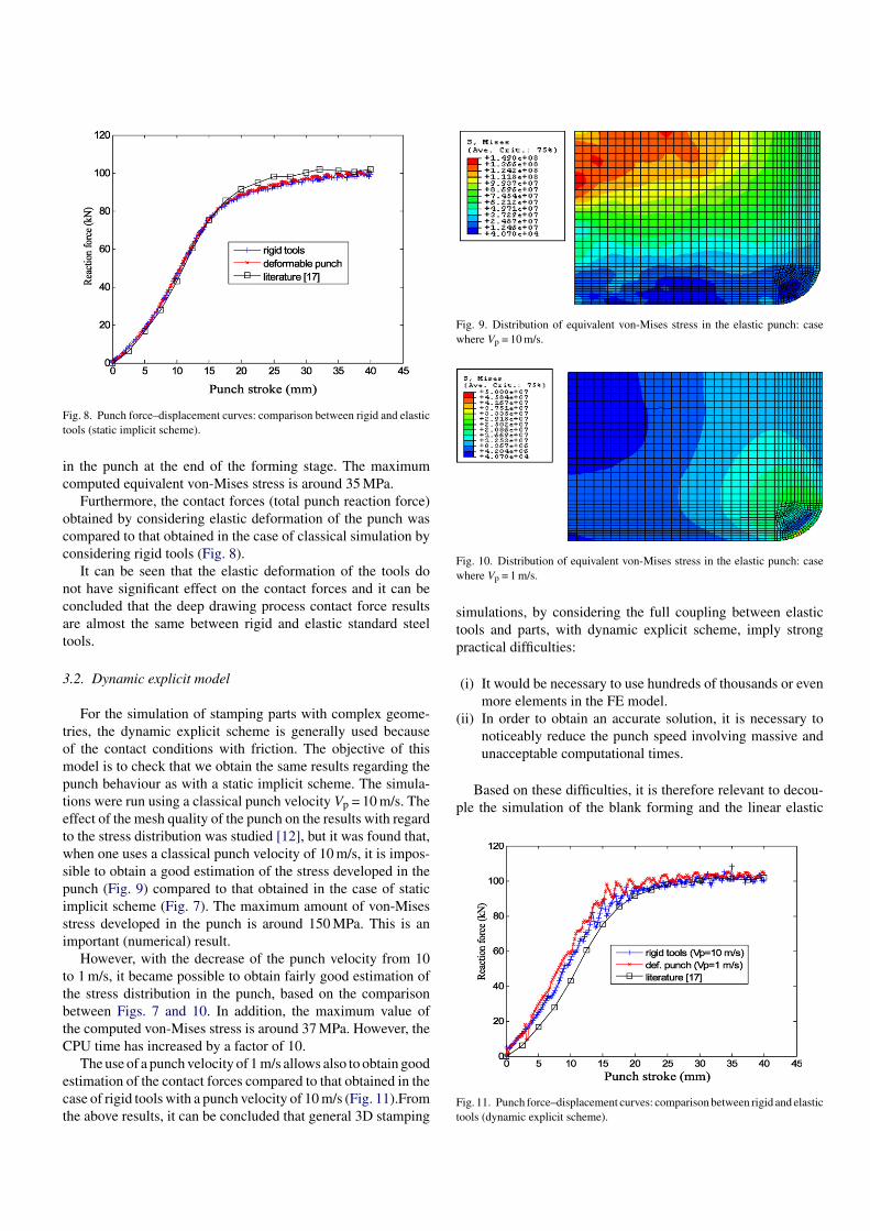
Fig. 8. Punch force–displacement curves: comparison between rigid and elastictools (static implicit scheme).
in the punch at the end of the forming stage. The maximumcomputed equivalent von-Mises stress is around 35 MPa.
Furthermore, the contact forces (total punch reaction force)obtained by considering elastic deformation of the punch wascompared to that obtained in the case of classical simulation byconsidering rigid tools (Fig. 8).
It can be seen that the elastic deformation of the tools donot have significant effect on the contact forces and it can beconcluded that the deep drawing process contact force resultsare almost the same between rigid and elastic standard steeltools.
3.2. Dynamic explicit model
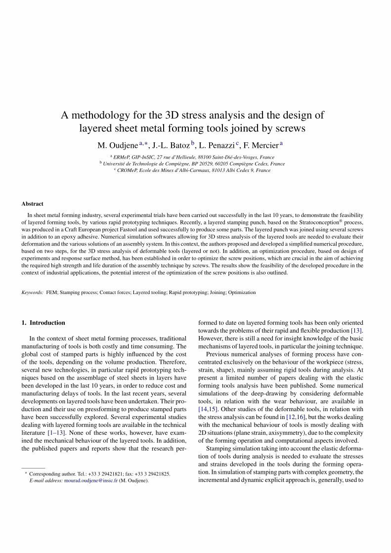
For the simulation of stamping parts with complex geome-tries, the dynamic explicit scheme is generally used becauseof the contact conditions with friction. The objective of thismodel is to check that we obtain the same results regarding thepunch behaviour as with a static implicit scheme. The simula-tions were run using a classical punch velocity Vp = 10 m/s. Theeffect of the mesh quality of the punch on the results with regardto the stress distribution was studied [12], but it was found that,when one uses a classical punch velocity of 10 m/s, it is impos-sible to obtain a good estimation of the stress developed in thepunch (Fig. 9) compared to that obtained in the case of staticimplicit scheme (Fig. 7). The maximum amount of von-Misesstress developed in the punch is around 150 MPa. This is animportant (numerical) result.
However, with the decrease of the punch velocity from 10to 1 m/s, it became possible to obtain fairly good estimation ofthe stress distribution in the punch, based on the comparisonbetween Figs. 7 and 10. In addition, the maximum value ofthe computed von-Mises stress is around 37 MPa. However, theCPU time has increased by a factor of 10.
The use of a punch velocity of 1 m/s allows also to obtain goodestimation of the contact forces compared to that obtained in thecase of rigid tools with a punch velocity of 10 m/s (Fig. 11).Fromthe above results, it can be concluded that general 3D stamping
Fig. 9. Distribution of equivalent von-Mises stress in the elastic punch: casewhere Vp = 10 m/s.
Fig. 10. Distribution of equivalent von-Mises stress in the elastic punch: casewhere Vp = 1 m/s.
simulations, by considering the full coupling between elastictools and parts, with dynamic explicit scheme, imply strongpractical difficulties:
(i) It would be necessary to use hundreds of thousands or evenmore elements in the FE model.
(ii) In order to obtain an accurate solution, it is necessary tonoticeably reduce the punch speed involving massive andunacceptable computational times.
Based on these difficulties, it is therefore relevant to decou-ple the simulation of the blank forming and the linear elastic
Fig. 11. Punch force–displacement curves: comparison between rigid and elastictools (dynamic explicit scheme).

analysis of the tools. Thus, the 3D stress analysis of the toolscan be performed separately by exploiting the knowledge of thedistribution of the contact forces acting on the rigid tools duringthe forming operation.
4. Description of the proposed method
4.1. Principle and assumptions
The contact forces acting on the rigid tools during the formingoperation have been found almost identical to those acting onthe real standard steel tools (see Section 3). Hence, the stressanalysis of tools can be performed using the classical stampingsimulation approach by considering rigid tools and by exploitingthe knowledge of the distribution of the resulting contact forces.Thus, our procedure involves two separate steps (Fig. 12):
(i) Step 1. The stamping simulation is first conducted clas-sically by considering rigid tools, allowing to obtain anestimation of the distribution of the contact forces actingon the rigid tools during the forming operation;
(ii) Step 2. The stamping tool (layered or not) is analyzed sepa-rately by considering its elastic deformation and by applyingthe distribution of the contact forces computed previously(in step 1) and considered as static external load.
In the present study, the STAMPACK finite element code andthe CATIA V5 finite element module were used to perform thesteps 1 and 2, respectively.
The above procedure, in two steps, is based on the assump-tion that the contact forces acting on the rigid tools arealmost identical to those acting on the real steel deformableones.
4.2. Estimation of the contact forces
In the beginning of the step 1, the surface of the rigidtool (active tool parts) is divided into small sectors called“Sets” (Fig. 13). For each “Set” (i), the global nodal contactforce vector, with its three cartesian components, is automati-cally computed in STAMPACK [18] and can be expressed asfollows:
F (i) =nnd∑
j=1
F(i)j (1)
with F(i) = (F (i)x , F (i)
y , F (i)z ), where nnd is the number of nodes
in “Set” (i).The third component F (i)
z represents the vertical punch reac-tion force acting on the “Set” (i). Then, the total punch reactionforce, denoted FZ, can be expressed as follows:
FZ =nset∑
i=1
F (i)z (2)
where nset is the number of sectors (or “Sets”) in the active toolparts.
Fig. 12. Procedure for the 3D FE analysis and the design of deformable forming tools.
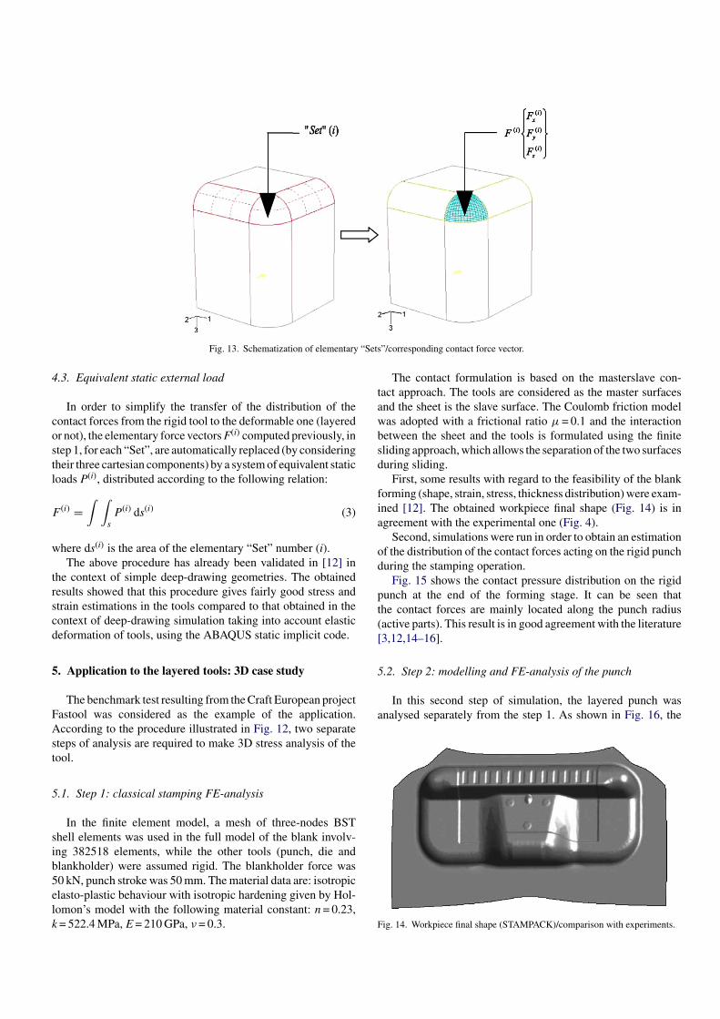
Fig. 13. Schematization of elementary “Sets”/corresponding contact force vector.
4.3. Equivalent static external load
In order to simplify the transfer of the distribution of thecontact forces from the rigid tool to the deformable one (layeredor not), the elementary force vectors F(i) computed previously, instep 1, for each “Set”, are automatically replaced (by consideringtheir three cartesian components) by a system of equivalent staticloads P(i), distributed according to the following relation:
F (i) =∫ ∫
sP (i) ds(i) (3)
where ds(i) is the area of the elementary “Set” number (i).The above procedure has already been validated in [12] in
the context of simple deep-drawing geometries. The obtainedresults showed that this procedure gives fairly good stress andstrain estimations in the tools compared to that obtained in thecontext of deep-drawing simulation taking into account elasticdeformation of tools, using the ABAQUS static implicit code.
5. Application to the layered tools: 3D case study
The benchmark test resulting from the Craft European projectFastool was considered as the example of the application.According to the procedure illustrated in Fig. 12, two separatesteps of analysis are required to make 3D stress analysis of thetool.
5.1. Step 1: classical stamping FE-analysis
In the finite element model, a mesh of three-nodes BSTshell elements was used in the full model of the blank involv-ing 382518 elements, while the other tools (punch, die andblankholder) were assumed rigid. The blankholder force was50 kN, punch stroke was 50 mm. The material data are: isotropicelasto-plastic behaviour with isotropic hardening given by Hol-lomon’s model with the following material constant: n = 0.23,k = 522.4 MPa, E = 210 GPa, ν = 0.3.
The contact formulation is based on the masterslave con-tact approach. The tools are considered as the master surfacesand the sheet is the slave surface. The Coulomb friction modelwas adopted with a frictional ratio µ = 0.1 and the interactionbetween the sheet and the tools is formulated using the finitesliding approach, which allows the separation of the two surfacesduring sliding.
First, some results with regard to the feasibility of the blankforming (shape, strain, stress, thickness distribution) were exam-ined [12]. The obtained workpiece final shape (Fig. 14) is inagreement with the experimental one (Fig. 4).
Second, simulations were run in order to obtain an estimationof the distribution of the contact forces acting on the rigid punchduring the stamping operation.
Fig. 15 shows the contact pressure distribution on the rigidpunch at the end of the forming stage. It can be seen thatthe contact forces are mainly located along the punch radius(active parts). This result is in good agreement with the literature[3,12,14–16].
5.2. Step 2: modelling and FE-analysis of the punch
In this second step of simulation, the layered punch wasanalysed separately from the step 1. As shown in Fig. 16, the
Fig. 14. Workpiece final shape (STAMPACK)/comparison with experiments.
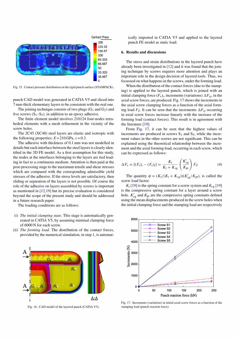
Fig. 15. Contact pressure distribution on the rigid punch surface (STAMPACK).
punch CAD model was generated in CATIA V5 and sliced into7 mm-thick elementary layers to be consistent with the real one.
The joining technique consists of two plugs (G1 and G2) andfive screws (S1–S5), in addition to an epoxy adhesive.
The finite element model involves 210124 four-nodes tetra-hedral elements with a mesh refinement in the vicinity of thescrew holes.
The 2C45 (XC48) steel layers are elastic and isotropic withthe following properties: E = 210 GPa, ν = 0.3.
The adhesive with thickness of 0.1 mm was not modelled indetails but each interface between the steel layers is clearly iden-tified in the 3D FE model. As a first assumption for this study,the nodes at the interfaces belonging to the layers are tied lead-ing in fact to a continuous medium. Attention is then paid at thepost-processing stage to the maximum tensile and shear stresseswhich are compared with the corresponding admissible yieldstresses of the adhesive. If the stress levels are satisfactory, thensliding or separation of the layers is not possible. Of course therole of the adhesive on layers assembled by screws is importantas mentioned in [12,19] but its precise evaluation is consideredbeyond the scope of the present study and should be addressedin a future research paper.
The loading conditions are as follows:
(i) The initial clamping state. This stage is automatically gen-erated in CATIA V5, by assuming minimal clamping forceof 6000 N for each screw.
(ii) The forming load. The distribution of the contact forces,provided by the numerical simulation, in step 1, is automat-
Fig. 16. CAD model of the layered punch (CATIA V5).
ically imported in CATIA V5 and applied to the layeredpunch FE model as static load.
6. Results and discussions
The stress and strain distributions in the layered punch havealready been investigated in [12] and it was found that the join-ing technique by screws requires more attention and plays animportant role in the design decision of layered tools. Thus, wefocussed on what happens in the screws, under the forming load.
When the distribution of the contact forces (due to the stamp-ing) is applied to the layered punch, which is joined with aninitial clamping force (Fs)i, increments (variations) "Fsj, in theaxial screw forces, are produced. Fig. 17 shows the increments inthe axial screw clamping forces as a function of the axial form-ing load FZ. It can be seen that the increments "Fsj occurringin axial screw forces increase linearly with the increase of theforming load (contact forces). This result is in agreement withthe literature [19].
From Fig. 17, it can be seen that the highest values ofincrements are produced in screws S1 and S5, while the incre-ment values in the other screws are not significant. This can beexplained using the theoretical relationship between the incre-ment and the axial forming load, occurring in each screw, whichcan be expressed as follows:
"Fs = [(Fs)i − (Fs)f] = Kt
Kt + Kcg
(K′
cg
Kpt
)FZ (4)
The quantity φ = (Kt/(Kt + Kcg))(K′cg/Kpt), is called the
screw load factor.Kt [19] is the spring constant for a screw system and Kcg [19]
is the compressive spring constant for a layer around a screwhole. K′
cg and Kpt are the compressive spring constants definedusing the mean displacements produced in the screw holes whenthe initial clamping force and the stamping load are respectively
Fig. 17. Increments (variations) in initial axial screw forces as a function of thestamping load (punch reaction force).

acting. (Fs)i and (Fs)f are respectively the initial and the finalaxial screw forces.
The slopes of "Fsj (Fig. 17) are independent of the initialclamping force (Fs)i and can be used in order to obtain theindividual screw load factors.
On the other hand, it is found that the value of(Fs)f(=(Fs)i + "Fs), in each screw, decreases because the valueof "Fs is negative.
In such screwed joint, the initial pre-stressed screws shouldremain in tension under the loading conditions, for a properstrength of the joint. Hence two problems, related to this joiningtechnique, can be identified:
(i) The decrease in the initial clamping force, due to the formingload, is not allowed when the final screw clamping forcetends to zero (this can leads to screw loosening);
(ii) The increment occurring in the axial screw clamping forcecan leads to large force increments in the screws, which cangreatly affect the fatigue behaviour (inducing cyclic stress inthe screws). The cyclic stress in each screw can be expressedas follows:
σcycl = (Fs)i − (Fs)f
2As= "Fs
2As(5)
where As is the cross-section of the screw.Based on these remarks, it appears then necessary to reduce
the increments occurring in axial screw clamping forces, dueto the forming load, in order to improve the strength and thelife duration of the joining technique. This can be achieved byoptimizing the positions of the screws.
7. Optimization of the screw positions
7.1. Formulation of the optimization problem
Here, only the screw positions Pj are considered as the designvariables. The final objective is to obtain in a layered punch inwhich the increments occurring in the axial screw forces are assmall as possible. Each screw position Pj is then defined by thecartesian coordinates (xj, yj) of the screw hole center, leading totwo design variables per screw.
7.2. Cost function
The cost (or objective) function we consider in this paper isdefined in terms of the increments occurring in the axial screwforces, such that:
F = 1ns
ns∑
j=1
["σsj]2 = 1ns
ns∑
j=1
[(σsj)i − (σsj)f]2 (6)
where "σsj = (Fsj)i − (Fsj)f/Asj is the pre-stress variation inscrew j, expressed as a function of initial and final axial screwforces (Fsj)i and (Fsj)f, and the screw cross section Asj. ns is thescrew number.
Fig. 18. Illustration of the design constraints.
A normalized form of Eq. (6) is defined as follows:
fcost = F − Fmin
Fmax − Fmin(7)
7.3. Design constraints
The research domain of the design variables is bounded tosatisfy the design rules of screwed joints [20]. For example, thedistance T between screw axes, and the distance L between screwaxes and outside edge of layers (Fig. 18) are closely related to thescrew diameter d. These feasibility constraints can be expressedas inequality relations [20]:
G ={
1.5d ≤ L ≤ 3.5d
3.5d ≤ T ≤ 7d(8)
where d is the screw diameter.
7.4. Optimization strategy
To solve the optimization problem, computations based onthe design of experiments (DoE) technique were conducted andcoupled to an optimization method in Matlab. The initial opti-mization problem based on the DoE with five screws leadingto 10 design variables involves 2n + 2n + 1 = 1045 (n = 10 designvariables) FE-analyses in CATIA V5 (if the central compositeDoE with three levels for each variable is considered). How-ever, the effort and experimental cost required for such a designcould be prohibitive and unrealistic. In order to reduce the sizeof the problem (the number of design variables), we did adoptthe following strategy:
(i) First, the displacements of the screws S1 and S5 in the Ydirection are eliminated because of the small width of thelayers (Fig. 18);
(ii) Second, the screws S2, S4, and S3 are restrained to moverespectively according to the (D) and (D′) axes.

Table 1
Initial and final parameters
Initial Final
fcost (%) 100 73P1 (x1, y1) (35, −56) (35, −56)P2 (x2, y2) (115, −55.5) (110, −53.5)P3 (x3, y3) (180, −52) (178.2, −42)P4 (x4, y4) (190, 19) (186.5, 15.8)P5 (x5, y5) (148, 55.5) (112, 55.5)
Thus the problem is reduced to five design variables (onevariable per screw). In addition, preliminary simulations showthat the optimization problem can be transformed in two sepa-rate sub-problems since it is found that there is no interactionbetween the positions of screws S1 and S5 with the other ones.Thus the initial optimization problem can be conducted in twosteps:
(i) Step 1. The positions of screws S1 and S5 are first optimized(optimization step with two design variables).
(ii) Step 2. The positions of screws S2–S4 are then optimized(optimization step with three design variables).
8. Optimization results
As shown in Table 1, the developed optimization proce-dure allows to noticeably reduce the individual screw pre-stressincrements, due to the forming load. In this case study, theminimization of the cost function (fcost) reaches 27%.
9. Conclusion
In this paper, a simplified numerical procedure for the 3D FE-analysis of deformable stamping tools is proposed and discussedwith particular attention to the analysis of layered tools joinedby adhesive and screws. The stress analysis procedure is basedon the decoupling of the simulation of the blank forming withthe elastic analysis of the deformable tools.
The adhesive is not fully considered in the present analysis,but the stress field is particularly analyzed at the layer interfacesto check the validity of the assumption of material continuity.
The numerical approach has been applied on the industrialapplication of a layered punch designed and manufactured usingthe Stratoconception® system. The following remarks can bementioned:
(i) The decrease in screw pre-stresses are highly related to thestamping load and also to the spring constants of the joinedlayers around the screw holes. It is then advisable to reducethese decreases, as much as possible, by considering bothappropriate screw positions and minimum allowable heightof the layered tooling;
(ii) The initial clamping force must be considered as an impor-tant parameter to guarantee minimal tensile force in axialscrews when the decrease in axial screw force is large;
(iii) The decrease in axial screw forces can lead to large stressincrements (or variations) in the screws, which can affectthe fatigue behaviour.
In order to improve the design of the layered forming toolsjoined by screws, an optimization procedure has been proposedto optimize the screw positions. The results show its ability toreduce the force increments occurring in each screw, due to theforming load.
More detailed research works can be proposed such as
(i) Advanced modelling of the layer interfaces to estimate moreprecisely the role of contact with friction and adhesive mate-rial on the compliance and the 3D stresses in the layeredtooling and screws.
(ii) Influence of inertia forces, vibrations and fatigue on thebehaviour, integrity and life duration of the non-standardlayered tools.
Acknowledgments
The authors would like to thank: Dr. A. Delameziere fromERMeP/GIP-InSIC for the fruitful discussions regarding theDesign of Experiments and the response surface method; Dr.Laurentiu Neamtu from Quantech ATZ (Spain) for the helpfuldiscussions regarding the use of the STAMPACK finite elementcode; CIRTES Company for providing informations on the CraftEuropean Project Fastool.
References
[1] T. Nakagawa, Advanced in prototype and low volume sheet forming andtooling, J. Mater. Process. Technol. 98 (2000) 244–250.
[2] D.H. Mueller, H. Mueller, Rapid Prototyping Techniques to ManufactureSheet Metal Forming Tools, ISATA, Dublin, Ireland, 2000.
[3] M. Oudjene, J.-L. Batoz, F. Mercier, L. Penazzi, C. Pelaingre, Mechanicalanalysis of prototyping tools for sheet metal stamping, in: Proceedings ofRPD2004 Advanced Solutions and Development, Marinha Grande, Portu-gal, October 12–13, 2004.
[4] H. Muller, J. Sladojevic, Rapid tooling approaches for small lot productionof sheet metal parts, J. Mater. Process. Technol. 115 (2001) 97–105.
[5] D.F. Walczyk, D.H. Hardt, Design and analysis of recomfortable discretedies for sheet metal forming, J. Manuf. Syst. 17 (6) (1998) 436–454.
[6] D.F. Walczyk, D.H. Hardt, Rapid tooling for sheet metal forming usingprofiled edge laminations—design principles and demonstration, J. Manuf.Syst. 120 (1998) 746–754.
[7] D.F. Walczyk, D.H. Hardt, A comparison of rapid fabrication methods forsheet metal forming dies, J. Manuf. Syst. 121 (1999) 214–224.
[8] P.M. Dickens, Principles of design for laminated tooling, Int. J. Prod. Res.35 (N5) (1997) 1349–1357.
[9] C. Abel, L. Velnom, C. Barlier, P. Poirier, FASTOOL et MOL-STRA; Deux projets europeens de recherche collaborative en PME(CRAFT)—Integration du procede de Stratoconception® en outillagerapide direct pour l’injection, l’emboutissage et la fonderie sous pression,Micad 2003, Paris, avril 1–3, 2003.
[10] B. Wadman, Fluid cell forming tools produced by different rapid proto-typing methods, in: Proceedings of the 22th International Deep DrawingResearch Group Congress, Bled, Slovenia, 2003, pp. 205–214.
[11] M. Oudjene, F. Mercier, L. Penazzi, J.-L. Batoz, 3D finite element modelingand analysis of the laminated tooling behaviour in sheet metal stampingprocess, in: Proceedings of the 24th International Deep Drawing ResearchGroup Congress, Besanon, France, June 20–22, 2005, p. 10.

[12] M. Oudjene, Modelisation et optimisation du comportement mecaniquedes outils d’emboutissage stratifies precontraints par vissage, Ph.D. Thesis,Institut National Polytechnique de Lorraine, Nancy, France, 2005.
[13] T. Pepelnjak, K. Kuzman, Adaptable tooling sets for metal forming ofgeometrically similar products, J. Mater. Process. Technol. 80/81 (1998)413–420.
[14] J. Dankert, Reduction of the residual stresses in a deep-drawing cup bymodifying the draw die profile, Ann. CIRP 44/1 (1995).
[15] F.F. Damborg, M.R. Jensen, K.B. Nielsen, J. Dankert, Optimization of thedraw die profile with regard to wear using the FEM, in: Proceedings of the19th International Deep Drawing Research Group Congress, Eger, June10–14, 1996.
[16] M. Burlat, Analyse Mecanique et Tribologique de l’Emboutissage: appli-cation aux Outils fabriques par combinaison de differents materiaux, Ph.D.Thesis, Institut National des Sciences Appliquees de Lyon, 1998.
[17] A. Makinouchi, E. Nakamachi, E. Onate, R.H. Wagoner (Eds.), Pro-ceedings of the 2nd International Conference Numerical Simulation of3-D Sheet Metal Forming Processes—Verification of Simulation withExperiments (Numisheet’2002), Isehara, Japan, 31 August–2 September,2002.
[18] A.T.Z. Quantech, Stampack User Guide—Version 5.6, Quantech edt., Edi-ficio Nexus, Gran Capitn, 2-4, 08034, Barcelona, Spain, 2004.
[19] M. Yoneno, T. Sawa, T. Ishihara, The strength of joints combining adhe-sives with bolts (case where adherends are pipe flanges of which theinterfaces are bonded partially), JSME Int. J., Ser. A 42 (1) (1999) 126–134.
[20] Centre Technique Industriel de la Construction Metallique, Regles de cal-cul des constructions en acier “Regles CM66”, Editions Eyrolles, 11emeedition, 1995.
[21] http://www.cirtes.fr.
Related Documents