1 A MATHEMATICAL WEAVER’S NOTES AND GUIDE TO: Shaft Weaving and Graph Design, By Olivier Masson and Francois Roussel Anne Wells June 2000

Welcome message from author
This document is posted to help you gain knowledge. Please leave a comment to let me know what you think about it! Share it to your friends and learn new things together.
Transcript
1
A MATHEMATICAL WEAVER’SNOTES AND GUIDE TO:
Shaft Weaving and Graph Design,By Olivier Masson and Francois Roussel
Anne WellsJune 2000
2
INTRODUCTION TO THE NOTES
The Notes that follow are meant to supplement, and not to replace, the translationof the book Shaft Weaving and Graph Design by Olivier Masson and Francois Roussel,hereinafter referred to as M&R. All quotes and references are to the translation. TheNotes’ organization is as follows: a summary of M&R’s entire book is provided,summarizing and identifying book sections of interest to weavers and expressing myopinion regarding sections that are of less interest to weavers. This summary isdesignated Part One – Content Summary. It is followed by Part Two – Detailed Notesand Guide, which follows the organization of Shaft Weaving and Graph Design.Frequent page references are incorporated into the Notes so that the reader can moreeasily relate the Notes to the book.
A reviewer of these Notes commented that Shaft Weaving and Graph Designreminded him of a book “Mathematics Made Difficult”, saying that this is “WeavingMade Difficult by Mathematics.” It is my hope that these Notes will allow weaverswithout a great deal of math in their backgrounds to get through this book. Many of thenotes made will hopefully trigger some mathematical memories and help the reader toappreciate some of the connections between weaving and mathematics. Even if thereader feels completely un-mathematical and skips all the parenthetical explanatory mathnotes, much of what M&R wrote should be more understandable with the help of theseNotes. Wherever I have made a “note” to the reader to explain or to supplement what iswritten in the book, I have used the format: [Note: explanation].
During the summer of 1999, several weavers provided support and specifictechnical advice, including Alice Schlein and Marguerite Gingras. Additionally, twoweavers with very strong math backgrounds reviewed the Notes as I wrote them andmade invaluable contributions to their clarity, while also catching many errors. They areMax Hailperin and Ralph Griswold. I am very grateful to both for the time and care theytook reviewing this work. Many of the insights contained in these Notes are courtesy ofMax and Ralph. And I must take all the credit for any remaining mathematical errorsthat exist herein.
Finally, special thanks must go out to Janet Forrest, who was the very first personI found as anxious as myself to clarify this book. We have had several years of emailconversations on this work and on how best to make the translation more intelligible toweavers who do not have the French edition. Janet added many editorial and interpretivecomments to these notes that I believe weavers will find very useful.
I’ve learned a great deal about designing and weaving from this book. It has a lotto offer weavers at all levels of expertise. I hope that these Notes will help to make thecontents of the book more accessible to all who are interested.
Anne WellsMay 2000
3
Table of Contents
Introduction to the Notes ……………………………………………….. page 2
Part One - Content Summary ……… …………...……………………... page 4
Overall Organization ……………………………………………………… page 6Part One – Mathematical Models …………………………………………. page 6Part Two – Transformation Bases ………………………………………… page 9Part Three – Contexturizing ………………………………………………. page 10
Part Two – Detailed Notes and Guide ………………………………… page 12
Preface ……………………………………………………………………. page 14Organization of the Book ………………………………………………… page 14
Part One – Mathematical Models of the Fabric Draft
Section A – Fabric Draft Definition ……………………………………… page 15Section B – Pegplan Type Treadling, Straight Tie-up, Threading ……….. page 16Section C – Representation Type “Treadling – Tie-up – Threading” …….. page 28Section D – First Practical Consequences of the Fabric Formula ………… page 29
Part Two – Transformation Bases
Section A – Theoretical Study …………………………………………… page 34Section B – Practical Study of Telescoping ……………………………… page 37
Part Three – Contexturizing
Section A – Block Method ……………………………………………….. page 41Section B – Method of Drafting on a Network ……………… ………… page 52Section C – Synthesis Essay ……………………………………………… page 59

4
PART ONE - CONTENT SUMMARY
5
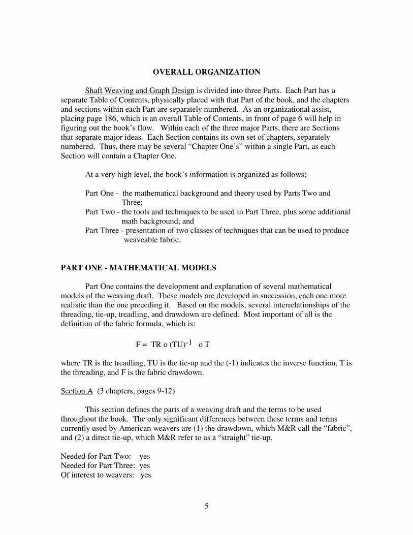
OVERALL ORGANIZATION
Shaft Weaving and Graph Design is divided into three Parts. Each Part has aseparate Table of Contents, physically placed with that Part of the book, and the chaptersand sections within each Part are separately numbered. As an organizational assist,placing page 186, which is an overall Table of Contents, in front of page 6 will help infiguring out the book’s flow. Within each of the three major Parts, there are Sectionsthat separate major ideas. Each Section contains its own set of chapters, separatelynumbered. Thus, there may be several “Chapter One’s” within a single Part, as eachSection will contain a Chapter One.
At a very high level, the book’s information is organized as follows:
Part One - the mathematical background and theory used by Parts Two and Three;Part Two - the tools and techniques to be used in Part Three, plus some additional
math background; andPart Three - presentation of two classes of techniques that can be used to produce
weaveable fabric.
PART ONE - MATHEMATICAL MODELS
Part One contains the development and explanation of several mathematicalmodels of the weaving draft. These models are developed in succession, each one morerealistic than the one preceding it. Based on the models, several interrelationships of thethreading, tie-up, treadling, and drawdown are defined. Most important of all is thedefinition of the fabric formula, which is:
F = TR o (TU)-1 o T
where TR is the treadling, TU is the tie-up and the (-1) indicates the inverse function, T isthe threading, and F is the fabric drawdown.
Section A (3 chapters, pages 9-12)
This section defines the parts of a weaving draft and the terms to be usedthroughout the book. The only significant differences between these terms and termscurrently used by American weavers are (1) the drawdown, which M&R call the “fabric”,and (2) a direct tie-up, which M&R refer to as a “straight” tie-up.
Needed for Part Two: yesNeeded for Part Three: yesOf interest to weavers: yes
6
Section B (3 chapters, pages 13-59)
This section develops the representation of the draft’s components (tie-up,threading, treadling, drawdown) first in terms of real functions. The purpose is to show amathematical relationship between the components, and ultimately to show that thedrawdown (or “fabric”) can be shown as a function of the threading and treadling when adirect tie-up is used.
Much of this section depends on using monotonic functions to represent thecurves (if one “connects the dots”) created by the threading, treadling, and drawdown).With this assumption, M&R are able to develop relationships between the draft elements.They also spend some time looking at the rate-of-change, or slope, of these lines as wellas the direction of the slope. Once they show that the drawdown curve is a function ofthe treadling and threading, they are able to show impacts on the drawdown of variouschanges in slope of the treadling and threading as well as impacts due to the differencesin direction of slope of the threading and treadling. They show the impact on thedrawdown of expanding and contracting the threading and treadling curves.
M&R conclude the first portion of this section by noting that functions used torepresent the threading and treadling lines are usually neither continuous nor monotonic.They address the issue of dealing with non-monotonic functions by noting that thefunctions can be divided, piece-wise, into sections each of which is individuallymonotonic. Thus, one can separate the drawdown elements in order to have sections thatare monotonic and for which the characteristics developed earlier in Section B apply.
The next portion of Section B develops a more refined and realistic mathematicalmodel of the fabric draft components. M&R note that “curved lines” usually are notadequate to represent the tie-up or treadling, and that weaving is based on a finite numberof threads, treadles, and shafts rather than the infinite number assumed by use ofcontinuous functions. So, they develop a model of the draft based on use of relationsdefined on an interval of points. Many definitions are provided, and some constraints aredefined. The constraints do not in any way detract from the accuracy of this model forweaving, however. Eventually, M&R are able to show that the drawdown is exactly thecomposite of two relations: TR (treadling) and T (threading). This model is developedassuming a direct tie-up.
Once this model is defined, M&R show how it can be used to understand theimpacts of change to one part of the draft on the drawdown. They discuss(mathematically) reflections and rotations around vertical and horizontal lines ofsymmetry. They introduce a fair amount of math to get this done.
The final chapter of this section briefly introduces a third mathematical model --one that uses a matrix to represent each element of the draft. M&R then quickly showthat, using logical operations, the matrix representation nicely supports the calculation ofTR o T to get the drawdown. Subsections 2 and 3 of this final chapter would have been
7
better if their order had been reversed: the notations and concepts used in subsection 2 arenot explained until subsection 3.
Needed for Part Two: noNeeded for Part Three: noOf interest to weavers: limited
Section C (2 chapters, pages 59-66)
This section finally considers the problem of developing a mathematical modelfor the draft in which a direct tie-up is not used. To do this, M&R immediately transformthe tie-up into a direct tie-up and show how one can then find the mathematicalrepresentation of the drawdown.
The second half of this section is used to develop the concept of multiple draft. Inshort, the multiple draft contains two or more versions of the threading, tie-up, and
treadling which generate the same drawdown and are related as F = TR o TU-1 o T.The math preceding this portion of the book is used to develop the multiple draft concept.
Needed for Part Two: yes (concept of multiple draft)Needed for Part Three: yes (concept of multiple draft)Of interest to weavers: limited
Section D (6 chapters, pages 67-82)
In spite of its title (First Practical Consequences of the Weaving Formula), thissection has some very intensive math. It does not contain practical weaving information,per se. The first two chapters, although brief, look at more ways to represent a weavingdraft, and for the most part, make their points through more mathematical manipulationsof “the weaving formula.” The third chapter looks at the impacts of exchanging warpand weft (or threading and treadling). Most weavers will recognize this as the concept ofturned drafts, which M&R develop mathematically.
Chapter 4, one page in length, focuses on the tie-up for a draft having a straightthreading and straight treadling. M&R simply make the point that the drawdown is themirror image of the tie-up with respect to the first diagonal (a diagonal line drawnthrough the tie-up box).
The final two chapters of Part One are very mathematically intense. First, inChapter 5, M&R show how to calculate the treadling (or pegplan) once the fabricdrawdown and threading are known. They also show (mathematically) the way togenerate numerous drawdowns from a single threading that are related to the originallydesired drawdown and which contain elements of the original drawdown. Second, M&Rshow that the fabrics which are “treadled as threaded” under some circumstances containuseful symmetries in the drawdown. They show that for “treadled as threaded” fabrics,symmetry in the tie-up results in symmetry in the drawdown.
8
Needed for Part Two: noNeeded for Part Three: noOf interest to weavers: yes, but this requires making one’s way through a lot of math, or one can focus on just the diagrams.
PART TWO - TRANSFORMATION BASES
M&R use various transformation bases to alter the threading, tie-up, and treadlingin a draft. These bases are used to alter the threading in order to change the shaft order,or to reduce the scale of the design, or to enlarge the scale of the design. The bases areused to make corresponding changes to the tie-up and treadling.
M&R spend considerable time first explaining the mathematics of transformationbases before applying these ideas. In the application of transformation bases to weavedrafts, M&R provide insight into the effects on the designs, particularly curves, ofvarious types of transformation bases. They discuss both telescoping and digitizing, andthey provide some guidance regarding when each should be used at the end of this Part.
Section A (3 chapters, pages 85-108)
This section provides the mathematical background -- and definition of terms --for Section B of Part Two. Chapter 1 introduces the idea of mathematically changing thethreading, tie-up, and treadling but leaving the draft’s drawdown unchanged. The idea ofa “transformation base” is introduced, which is called B throughout, and which acts onthe elements of a draft in various ways. The term “amalgamated threading” isintroduced. It means a threading that is equivalent to the original threading, but one inwhich the visual organization of the original threading is obscured from view.
Needed for Part Three: noOf interest to weavers: no
The second chapter introduces the concepts of digitizing and telescoping. Bothare used to reduce the number of shafts used by a particular draft, but each method resultsin a different “look,” particularly for curves. A digitized curve has a stair-step look to it,while a telescoped curve has a set of harmonics that surround the original curves andlines. The final look of a digitized or telescoped set of curves and lines depends on theexact process used for the digitizing/telescoping (this is described in Section B).
Needed for Part Two: yesNeeded for Part Three: yesOf interest to weavers: yes, even if just the diagrams are examined
The final chapter in this section poses the problem of combining two drafts.M&R motivate this discussion by pointing out and contrasting the versatility of a straight
9
draw threading but its small repeat size, with the large repeat size but lack of versatility ina complex threading. The remainder of the chapter looks at how to combine two suchthreadings into one, using a brute force, shaft expensive technique. This is mostcommonly referred to as a “blended draft” in the U.S., and is described in severalweaving magazines and books.
Needed for Part Two: noNeeded for Part Three: noOf interest to weavers: limited (because it is better explained elsewhere in handweaving literature)
Section B (3 chapters, pages 109-120)
The focus of these chapters is the practical application of telescoping. There isvery little math in this section. However, the language of Section A is used extensively,as is the multiple draft notation.
The section starts with a presentation of two drafts, one showing “line effects”and one showing “surface opposition” effects in the draft’s drawdown area. The first partof Section B, Chapter One, then looks at the impacts of various telescoping techniques onthe drawdown emphasizing “line effects.” Chapter Two looks at the impacts oftelescoping and digitizing on the second example (“surface opposition”). The finalchapter pulls together the highlights from the first two chapters and also providesguidance to weavers regarding the choice of telescoping versus digitization. From themany examples provided in Section B, non-mathematical weavers can get a good idea ofhow telescoping and digitizing work.
Needed for Part Three: yesOf interest to weavers: yes
PART THREE - CONTEXTURING
This part of the book is focused on how to create new designs and weaves usingthe tools and techniques M&R discuss in the first two Parts of the book. The wordcontexturizing is used to describe the process of taking a profile design and creating acomplete weaving draft for it. Whereas the first two Parts have many theoreticaltechniques and tools for developing and manipulating designs, this Part is more focusedon how to manage the real world constraints of weaving theoretical designs.
All of Part Three is of interest to weavers.
Section A (3 chapters, pages 123 - 156)
All of Section A is directed toward designing with block profiles and how tocreate a practical weave from a block profile design. In Chapter 1, M&R give seven
10
examples of how to turn a particular block profile design into something one might beable to weave. In particular, this chapter looks at ways to generate weaving drafts forblock profile designs that use varying numbers of shafts. Options for large numbers ofshafts as well as options for just four shafts are provided in the examples.
While the first chapter relies on traditional structures known to most weavers, thesecond chapter encourages the weaver to try new threading arrangements to obtain moreunique weave structures. Included in this chapter are ways to use binding threads, waysto change the balance between binding/pattern threads, ways to expand blocks, and waysto make dependent blocks, independent. There is also some discussion of tie-ups thatmay be used with different block profile designs.
The final chapter looks at how best to use the telescoping techniques developed inPart Two with block profiles. M&R discuss how telescoping works differently forindependent blocks (blocks which have no pattern shafts common with other blocks) anddependent blocks. They provide advice regarding what kind of design is most amenableto telescoping (line effects rather than surface effects).
Section B (4 chapters, pages 157 - 174)
This section explains methods of drafting using an initial. It includes variousways to manipulate and select the initial to achieve specific design and weave effects.
The first chapter introduces the idea of a network and of an initial. M&Remphasize that networks are built in such a way that one can identify (and weave) twoopposing weaves. In this section, opposing weaves are weaves which offer strongcontrast to each other in texture, pattern, or structure. M&R show various ways toachieve this.
The second chapter explains how one can design a curve on a network and beginsto show how a networked curve behaves for different choices of the required twoopposing weaves. M&R provide six examples of opposing weaves at the end of thisshort chapter. One sees the relationship between the initial and the weave structure(s)selected for the two opposing weaves.
A great deal of information is presented in the last two chapters of this section.Various approaches to minimizing harmonics are discussed, use of telescoping isanalyzed, and some different ways to work with curves are suggested. There are manyexamples provided to the reader.
Section C (2 chapters, pages 175 - 184)
In this summary section, M&R pull together all the ideas presented in the first twosections. In the first chapter, they show six different ways (using both blocks and initials)to transform a simple block profile design to a complete weaving draft. There is cross-

11
over and blending between these techniques, which M&R have previously minimized forthe sake of clarity of presentation.
A second set of six examples, not related to each other, is provided in the secondchapter. These examples are meant to inspire the designer to try new ways of using thetechniques of this book.

12
DETAILED NOTES AND GUIDE

13
PREFACE
(Titled Warning, page 5)
M&R state that the objective of the book is, using the power of the computer, to breakloose of traditional weaving structures commonly associated with handloom weaving.Using the computer software developed by Masson (his POINTCARRE), M&R wishto explain the mathematical and theoretical basis for more complex structures and for theassociated design techniques in this book.
M&R compare the “near infinite” number of shafts of the Jacquard loom to the small,finite number of shafts on the handloom. This book seeks to help handweavers make themost of those finite number of shafts. [Note: Throughout the book, M&R repeatedly notethe many new design tools available to weavers via the computer. A great part of theimpetus for this book seems to be the -- as viewed by M&R -- powerful new designcapabilities offered via the computer which make possible design techniques previouslytoo labor intensive to be of much value or interest to handweavers.]
ORGANIZATION OF THE BOOK (Table of Contents)
Part I - Mathematical models of the draft, threading, tie-up, and treadling. This is thetheoretical discussion on which latter parts of the book are based.
Part II - Transformation Bases: techniques to modify the threading, tie-up, and treadlingto accommodate the constraints of the finite number of shafts on a handloom.
Part III - Contexturizing: techniques to create new designs using old structures in newways, based on what is presented in Parts I and II.
14
PART ONEMATHEMATICAL MODELS OF THE FABRIC DRAFT
SECTION A FABRIC DRAFT DEFINITION (page 9)
1- Representation of treadling, tie-up, and threading. (page 9)
M&R state that the fabric consists of two sets of threads perpendicular to each other.They define the following representational conventions: the threading and tie-up are incolumns read from left to right, and the shafts are ordered in rows from bottom (shaft 1)to top.
If one looks at this as though looking at a piece of graph paper, then in the tie-up thenumber of columns = number treadles, and the number rows = number shafts. If for agiven pick some warp threads are raised, then those warp threads raised are not coveredby the weft and the corresponding intersection of warp and weft is a square on the graphpaper that is colored in. The result of coloring the squares to correspond to raised warpends in each weaving pick provides a graphical representation of the fabric (small scale,bottom illustration of page 11). If one looks at a large scale graph (top illustration ofpage 11), one sees the structure of this fabric.
2 - Representation of the tie-up (page 12)
In this section, M&R state that if one uses a direct tie-up, then one sees the complete draftof the fabric in the treadling. (This is an unproved assertion at this point.) M&R notethat this is the treadling order one generally associates with the peg plan used for dobbyloom designing.
3 - How to represent the tie-up and treadling (given that two options exist) (page 12)
M&R discuss the pros and the cons of the above two systems. In the first system, wherethe tie-up contains information regarding the structure of the fabric, the treadling thatresults from this tie-up usually requires use of one treadle per weaving pick. In thesecond system, where the treadling contains the information concerning the structure ofthe fabric, a direct tie-up is used. They note that in actual operation, threading is thefixed part of the weaving: the tie-up and treadling can be changed as weaving progresses.However, they point out that for dobby looms, weaving information is concentrated in thepeg plan, and so they will begin with the direct tie-up type representation of the fabricdraft for Part One.
15
SECTION B PEGPLAN TYPE TREADLING, STRAIGHT TIE-UP, THREADING
Chapter One - Representation of the fabric draft using numerical functions (page 13)
1 - Representation of a draft by a real function (page 13)
a. Notation
This section is where M&R introduce the idea of using mathematical functions tounderstand the relationships between threading, tie-up, treadling, and the resultingfabric’s arrangement of warp and weft threads. Their notation:
f = tr ( t (td) )
means that the threads, represented by td, [Note: td is a two letter variable: most of us areaccustomed to a one letter variable such as x, or n] are operated on by the threading t (thefunction that defines how the threads are assigned to shafts in a threading), and are alsooperated on by the defined treadling (the function tr) to produce f, the fabric design.
[Math Note: Written functions operate inside-out. Hence, one starts reading from theright, inside the inner-most parentheses, and works one’s way out and to the left. In thissection, M&R talk about composite functions, e.g., tr o t. The small o is an operator usedto combine two functions. This, mathematically, is a composition (think combination) oftwo functions in a specific order: tr and t. The example given is confusing because ofpoor typing of the square root symbol. A letter V was used in combination with a straightline above the function, and the two were not always properly joined. The symbol
desired is the radical sign: √− . ]
M&R use some standard math functions that result in curves, by way of example.Nothing here is special to weaving; it is simply geometry and trigonometry. The onlypoint made is that there are simple math functions that can be used to represent curves.
At the end of this section, M&R state that they will deal with the following specific mathfunctions: strictly monotonic, continuous functions [Note: not monotonous].
[Note: The reason for selecting these is probably several hundred years’ worth of mathaccummulated from studying these functions, which in the world of math are consideredto be “well-behaved.” The tremendous amount of mathematical knowledge aboutcontinuous functions makes them ideal for this study.]

16
2 - Strictly monotonic, continuous functions (page 16)
M&R define these functions: they are functions which yield a line that is continuous (nobreaks, no holes, no gaps) and that is either always increasing (going up on a graph) oralways decreasing (going down on a graph) but which is never flat.
a) If you combine two strictly monotonic functions, the result is also a strictlymonotonic function; and
b) If one graphs the composite of two functions that are strictly monotonic(remember, we are interested in tr o t, the composite of the treadling andthreading functions) then the area where the graph is drawn is divided intotwo parts.
As the threading function is defined by M&R, it has the additional characteristic of being(mathematically) a bijection.
With these assumptions, M&R prove that the area below the curve (shown in the areawhere weavers expect to see the fabric drawdown) is directly related to the area belowthe curve of the treadling function. M&R then note that we will be able to extend thisrelationship to curves which are not strictly monotonic by looking at those curves insections and by demonstrating that for each section (where we choose the sections so thateach has a strictly monotonic curve) the relationship holds.
[Math Note: The equivalent concept is to look at certain functions to see that they arewhat is called piece-wise continuous, piece-wise strictly monotonic, and so on.]
c) Rules on composing (combining) functions:
- The combination of two increasing or two decreasing functions is anincreasing function.- The combination of an increasing and decreasing function is adecreasing function.
[Note: These are stated without proof.]
d) Gradients
[Note: This is a mathematical term used to describe the rate of change of a function. Intwo dimensions, a more common term is used: slope. All examples in this book are fortwo dimensions, so the word slope could be used everywhere.]
M&R give several examples of gradients for straight lines and move directly on to theabstract case of the two functions of interest: threading and treadling. They show that thegradient of these two functions combined ( tr o t ) has a gradient equal to the combinationof each function’s own gradient.
17
Now, M&R assume that the two functions T and TR are differentiable [Note: Notderivable]. This particular assumption allows more nice things to happen,mathematically. In short, at any point on the design curve, the gradient can be calculatedas the product of the threading and treadling functions’ gradients. [Note: Product hererefers to a mathematical operation that is not simple multiplication.]
e) Size variations
M&R describe eight design tools to vary the sizes of graphic designs. Each is wellillustrated to follow the text and each is the basis of a technique in a future section. Alltie-ups used in this section are direct tie-ups.
1. Straight Treadling. (page 21) This section looks at the consequences ofusing a direct tie-up and then treadling in the successive order of the tie-up. M&R provethat with the assumptions of this chapter, when one weaves with this tie-up and threading,then one produces the threading in the resulting fabric (see top diagram, page 21).
From this, M&R show that if the slope of the line “created by the treadling notation”using a direct tie-up is greater than one (1), the resulting fabric design line is elongated.When the slope of the treadling line is less than one (1), then the resulting fabric designline is shortened.
2. Straight (Draw) Threadings. (page 22) Now, M&R examine the casewhere the line created by the threading is straight. With a direct tie-up, the treadlingorder repeats the fabric design line. If one examines the slope of the line of the threading,one can conclude that if it has a positive slope less than one (1), then the line of the fabricdesign will be greater in width than the line in the treadling plan. If the line of thethreading has a positive slope greater than one (1), then the line of the fabric design willbe narrower than the line in the treadling plan (using a direct tie-up).
3. Height variation of the treadling. (page 23) This section looks at how theline of the fabric design changes when the line of the treadling is heightened or shortened(making the actual treadling sequence longer or shorter). This section continues theassumption of a direct tie-up, and assumes the threading function to be a monotonic(well-behaved) steadily increasing, curved line function. The authors prove that theresulting fabric design line is heightened or shortened in the same proportion that the lineof the treadling is heightened or shortened.
4. Threading width variation. (page 23) With reasoning similar to thepreceding section and making the same assumptions, M&R show that as the threadingline is elongated or shortened, then so is the fabric design line elongated or shrunk, inproportion.
5. Changes to threading width and treadling height. (page 24) Using themath of the preceding sections, one may conclude that if the threading line is either
18
elongated or shortened at the same time that the treadling order is lengthened ordecreased, then the fabric’s design line will be widened or narrowed and heightened orshortened.
6. Proportional changes in both threading line height and treadling line width.(Page 25) Changes in treadling line width here corresponds to increasing or decreasingthe number of shafts. In this section, M&R show mathematically that if the threading lineheight and treadling line width are changed simultaneously in the same proportion, thenthe fabric’s design line proportions are unchanged. M&R give a concrete mathematicalexample to demonstrate this symmetry in threading and treadling. (It is this symmetrythat is carried to the curve design.) . They also note that there are practical limitations ofthis theory: a reduction of shafts below a certain threshhold will affect the design line. Inthis case, it will flatten the threading curve and change the design.
M&R introduce practical results of the so-far theoretical functions. For the first time,they speak of digitized threading curves on fewer shafts. They introduce the reader to theidea of contexturizing: this is a process that starts with a design, then has the weavermake appropriate choices of weave structure(s) for the pattern and the background areasof that particular design, and concludes with the production of a weaving draft for thedesign using the structures selected. They illustrate that the designed curve will supportthe choice of one weave structure (armure) within and another weave structure outsidethe curve, maintaining the properties of each weave structure.
7. Reduction of threading height (reducing the number of shafts) with directtreadling order. (page 27) This section looks at the specific example of a circle. Thesimplest way to create the circle in the fabric’s design line is in the threading. With manyshafts, the design line is a good circle. With fewer shafts, M&R show that one can get agood design line (circle, in this case) by increasing the height of the treadling in theappropriate amount. In the example, one divides the number of shafts by 4 (or multipliesby 1/4) and multiplies the treadling line length by 4. This effectively multiplies the slopeof the line of the treadling order by 4 and results in a design line which is close in shapeto that on the original with the full number of shafts.
8. Reduction of treadling width. (page 28) This section partners thepreceding section. It shows that with a straight threading line and a curved (half circle)treadling line, one can decrease the width of the treadling line yet still preserve thegeneral shape of the fabric design line (a circle) if the threading height increases by thesame amount that the treadling line reduces in width. (This design tool is used in PartThree.)
3 - Non-monotonic functions used to represent the threading and treadling. (page 30)
M&R comment that the line of the threading used by weavers is usually not that of amonotonic function: real threading lines go up and down; they change direction. (Thecorresponding function representing the threading increases and decreases.)

19
M&R explain that by dividing the threading and treadling lines into sections that aremonotonic increasing or monotonic decreasing, one can show that since each sectionadheres to the rules just presented in Section 2, then so does the entire curve. [MathNote: They should really show that this holds at the intersections of the sections -- the“joins” -- in order to make this statement. However, they do not.]
Finally, the authors conclude Chapter One by saying that while this chapter assumed allfunctions were continuous; in actual practice, they are not. Therefore, a new (different)mathematical model of the fabric draft is needed. This leads the reader to the nextchapter.
Chapter Two - Representation of fabric draft with relations (page 31)
This chapter begins with a brief summary of the previous chapter and study using realnumerical functions. It states the following in this regard:
the pros - the ability to study the design line’s direction of variation and slope, and the amount of slope
- the consequences of extending (or stretching) the threading - the consequences of extending (or stretching) the treadling
the cons - drafts are limited to a description of curves, which is convenient but does not represent all the information in a typical weaving draft; they do not show the separation of weave surfaces
- the curves studied are represented by infinite sets of points and hence are at least piece-wise continuous, whereas the curves in a weaving design have a finite, discrete set of points that defines them.
M&R say that a different representation is required which is a better match with reality.They caution the reader that this new model requires more math, but that the results canbe summarized in a way understandable to all.
1- Representation of a draft with a relation (page 31)
a) Representation of drafts with relations
This section introduces M&R’s notation. N is used to represent the interval[1,n] = (1,2,3,......n). [Math note: A function has certain properties that a relation doesnot. A relation simply defines how one finds a number “y” once given the number “x.”A function has the additional constraint that each number “x” in the domain correspondsto a unique number y in the range.]
2 - Two restrictive conditions on the relations studied (page 32)
To provide a good match with the reality of a weave design, M&R require the followingproperties of drafts in this section:

20
a) there are no empty columns in the threading, or every warp thread is associatedwith a shaft. [Note: Mathematically, this corresponds to saying that for every x, there issome y which relates to that x, or the relation is defined everywhere.]
b) there are no empty rows in the threading, or in weaving, every shaft is used.[Note: Mathematically, this means that the entire range is used by the relation and therelation is called “onto,” or surjective.]
In addition to the threading, the same applies to the treadling (all treadles defined areused) and to the tie-up (each treadle is tied to at least one shaft and vice versa).
M&R comment that in a future explanation of the technique of digitizing curves, theremay be some unused lines and/or columns, but this is not relevant to Part One. In fact, inthe remainder of Part One, these restrictions (that the relation is defined everywhere andis surjective) are now globally assumed.
3 - A few definitions (page 33)
[Note: M&R offer some definitions, none of which is original. In many cases, the non-standard English words make it difficult to recognize these as basic math concepts.]
a) Application: a relation is an application only if for each number in the domainof the relation there is one number in the range and that number is unique. [Note: This isthe same definition as a function.] If one looks at a threading draft as the graph of arelation, then it is also an application (function) if each thread is assigned to one and onlyone shaft. Thus, any vertical line will cross the threading column in only one place if itrepresents a function.
b) Injective relation: a relation is injective if every time two numbers in itsdomain map to the same number in the range, then the two numbers in the domain mustbe the same number. [Math note: This is also called “one-to-one.”] As one looks at agraph of an injective relation, there can be only one filled square in a row. Anyhorizontal line will cross the design or treadling graph in only one place.
c) Bijective relation: a relation that is both an application (function) and aninjection is a bijective relation. The graph of a bijective relation is crossed only once byany horizontal line and only once by any vertical line. M&R note that if one looks at thegraph of a bijective relation with respect to weaving drafts, the area would be square withequal numbers of rows and columns.
4 - Composition of relations (page 36)
a) Definition. This section discusses two relations which when operating togetherform a new relation. The first sentence merely states that the domain of B is the range ofA. [Note: M&R put some weaving related terms into this otherwise pure math
21
discussion. They use “width” in place of domain (number of columns), and “height” inplace of range (number of rows).] M&R note that the composition of two functions isassociative (can be regrouped) but not commutative (cannot be reordered). The tworelations named A and B are used as names for the rules which govern how the points onthe threading curve are organized (A) and how the points on the treadling curve areorganized (B). When one starts with a point x on the threading curve, using the relationA one finds the correct point y which corresponds to a shaft. Then, one takes that point y(the shaft) and uses the relation B to identify the point z, shown on the design drawdown.These points are not unique, as shown on the diagram at the bottom of page 36. [Mathnote: The small o is used to mean that the two relations A and B are combined.]
b) Fabric Draft (straight tie-up representation used). This section states that if thethreading is represented by the function T and the treadling by the relation TR, then thedrawdown F of the fabric can be written as F = TR o T. [Note: The inconsistency incapitalizing T and TR adds to the confusion of this section. Also, although the definitionof F is very intuitive, there is no formal proof in this section that in fact F = TR o T.Mathematically, based on the discussion, one would say that F is defined to be TR o T.]
5 - Inverse relation (page 38)
This section defines inverse relations. [Note: On occasion, but not always, the inverse ofa relation is its reciprocal. Therefore, it is more correct to use the word inverse ratherthan the word reciprocal.] Several things are noted in this section about a relation A and
its inverse, A-1: the domain of A-1 is the range of A; the range of A-1 is the domain of
A; the inverse of A-1 is A; A is a function if and only if A-1 is an injection andconversely. In the middle of page 38, the inverse of a relation A is illustrated. One
notices that the columns of A are the rows of A-1 , and the columns of A-1 are the rowsof A. The inverse of A was found by reflecting A around the diagonal line shown.
[Note: Some unusual notation, possibly from the translation process, makes this sectiondifficult to read. For example, the three short lines stacked on top of each other typicallyhave a vertical line connecting them on the right, creating a backward capital E (∃)meaning “there exists.” When this is followed by a ! , for example ∃ !, that means “thereexists a unique ...”. Also, the capital C plus - (typed over each other) should be ∈, thesymbol for “is an element of,” and the capital V plus - (typed over each other) shouldbe an upside down capital A (∀) which means “for all.”]
6 - Symmetrical relation (page 39)
This section notes that a relation A is symmetric if A = A-1. When a diagonal line isdrawn through a design, one will see mirror symmetry on each side of the line.Therefore, this fabric relation is symmetric.

22
7 - First diagonal I, straight draft (page 40)
This section defines the identity function I (not the “identical application”). M&R notethat In is the first diagonal of a square that is n x n. They go back to the fabric designfunction F = TR o T and note that if either TR or T is the identity function, then thedesign F is equal to the treadling if T is the identify function or equal to the threading ifTR is the identify function. [Note: In this section, confusion may result from T beingreplaced with A and TR being replaced with B.]
To say that the threading is the identity function is to say that the threading is a straightdraw. To say that the treadling function is the identify function is to say that there is adirect treadling order. Visually, when one looks at the draft, the threading (or thetreadling order) would appear to be a diagonal line. In either case, since I o T = T andTR o I = TR, one can confirm the above result with the mathematics. For example, astraight draw threading means that T = I, so that in the equation F = TR o T one has F =TR o I, or F = TR, as stated above.
8 - Inverse of the composite of two relations (page 42)
This section shows how to find the inverse of a composite relation. It simply says that:
(B o A)-1 = A-1 o B-1.
This can be generalized to the composite of several relations, as shown at the bottom ofthe page for the case of three relations.
9 - Composite of a relation with its inverse (page 43)
a) Properties. First, M&R show that the composite relation A-1 o A is symmetricand its graph contains the identity function, the diagonal I.
b) Treadled as Threaded. When one treadles as threaded, then the resulting fabricdesign F is symmetric and contains the diagonal I. [Note: Although not directly stated,
one can see from the diagram that treadled as threaded implies TR = T-1. Thus, theresults from the previous sections apply here.]
c) Simplification rules. This section contains proofs of the following:
A is injective if and only if A-1 o A = I
A is a function if and only if A o A-1 = I
A is a bijection if and only if A-1 o A = A o A-1 = I

23
Finally, M&R show that all invertible relations are bijections, and that for a bijection, thenotions of inverse of a function and inverse of a relation coincide. They note that the
inverse of a function traditionally is written F-1, or the inverse of F.
10 - Involutive relation (page 47)
A relation is defined as involutive if it is both bijective and symmetric. Thus, A isinvolutive if A o A = I (or, A is equal to its own inverse and bijective). [Math note:There are other properties of involutive relations, but none of those are referred to byM&R and they are not needed in the subsequent discussions.]
11 - Second diagonal (-I). Twill draft (page 48)
This section defines the second diagonal -I (not -1) as bijective, symmetric, andinvolutive. [Note: The diagram at the top of the page uses I- in place of the correct -I,and the final statements refer to In when clearly -In is meant. Throughout, the wordensemble is meant to be set of points contained in an interval. Overall, the math notationis quite awkward in this section. However, it is true that if x and y are members of theinterval [1,n], then the first diagonal can be represented by the function y = x. Thesecond diagonal is represented by the function y = -x and the interval, or set of points,that x and y belong to is [-n, n]. An equally valid way to look at the second diagonal is toconsider -In as being a permutation on the interval [1,n] defined by y = n + 1 -x.]
12 - Calculations on straight twills and twill drafts (page 49)
This section provides rules for combining the first (In) and second (-In) diagonals. M&Rgive a memorization technique, or mnemonic, (“memotechnical” way) using the fourillustrations (top of page 49): either two positives or two negatives yield I, whereas apositive combined with a negative yields -I. These rules applied to twilled graphicillustrations with isolated repeats of I and -I diagonals show the reader how to quicklygenerate the correct directional inclination for any part of the graph.
13 - Geometric transformation of a draft (page 50)
a) Expression of a geometric transformation. In this section, a relation A is usedto represent the relation defining the design (an apple motif). The relation A ismanipulated to show the reader how various combinations of directional changes affectthe drawdown. Two examples are given to show the difference between -I o A andA o -I. For the first, -I o A, the result is symmetric with respect to the horizontal (or, wesay that a horizontal line of symmetry exists between A and -I o A). No change is madeto the treadling, described by the function -I. For the second, A o -I, the result issymmetric with respect to the vertical (or, we say that a vertical line of symmetry existsbetween A and A o -I).
24
Thus, by the proper composition of the relation A with the identity function I or -I (and here, proper means choosing the correct order of composition of A and -I) one canflip the design either vertically or horizontally to get its mirror image.
b) Expression of a general geometric transformation. This section discusses howa single motif can be transposed and reversed around a line of symmetry. Theseoperations on a motif are defined by M&R as being geometric transformations. (Thetextile design term is transposed.) They illustrate eight (8) of these on page 51. It’simportant to note here that the second row of motifs on page 51 is incorrectly identified:the order of the labels on that row are reversed, left to right.
M&R state that there are various ways to transform a motif, geometrically. Theyidentify the following three in this section:
- by combining turns and reverses (vertical and horizontal reflections) of the motif;- by a combination of a symmetrical composition (using I or -I) and a rotation ofthe motif;- by combining symmetries of the motif with respect to the first diagonal (I),inverse of the motif (M&R: reciprocal), and the second diagonal (-I).
Mathematically, this means looking at three transformations of A (and combinations of
these three transformations): A-1, -I o A, and A o -I. These three transformations providereflection across the main diagonal, reflection across the horizontal, and reflection acrossthe vertical.
Using these three, one can generate all eight simple geometric transformations of a motif.
c) Effects of symmetry on the fabric draft. This section shows via example andmathematical proof that if there is a particular threading T, and its mirror image is createdby reflecting it around a vertical line of symmetry (T o -I), then the resulting fabricdesign will also be the mirror image of the original design (with respect to a vertical lineof symmetry) and will be equal to F o -I.
If, instead, the treadling TR is reflected around a horizontal line of symmetry (-I o TR),then the fabric drawdown also will be reflected around a horizontal line of symmetry (-I o F).
Finally, M&R show via example and mathematically that a geometric transformation ofthe threading with respect to the horizontal and a geometric transformation of thetreadling with respect to the vertical leaves the fabric design (F) unchanged. They pointout that these two transformations correspond to changing the shaft numbers from top tobottom and the treadling from right to left. Combined, these changes have the effect ofcanceling each other, so that the design is unchanged.
25
This chapter ends with a set of examples showing various symmetric changes in thethreading and treadling with the resulting changes to the fabric design.
The last paragraph states that symmetry is bad for the fabric. Aside from designprinciples, what M&R may mean to say is that depending on how symmetry changes aremade, particularly regarding the assignments of shafts and treadles, there is a goodchance of changing the fabric F to some other design which is not symmetrically relatedto F. Just reflecting the threading around a horizontal line (without changing the pegplan)is generally bad. Similarly, just reflecting the pegplan around a vertical line (withoutchanging the threading) is bad. They also warn the reader of “careless symmetrychanges” which destroy the stability of the fabric structure (see bottom illustration onpage 54). (Of course, reflecting the threading around a vertical line, or the pegplanaround a horizontal line, is a common design strategy producing an acceptable fabric.)
Chapter Three - Representation of a Fabric Draft with a Matrix (page 55)
This chapter considers a new mathematical representation of a fabric draft with a matrix.
1 - Definitions (page 55)
This section begins by translating the elements of a weaving draft to matrix format. Thisis done by looking at the threading, treadling, and design as if each were drawn on graphpaper. The empty squares correspond to 0’s and the filled squares to 1’s. Elements ofthe matrix A are: a(i,j) , where i is the column number and j is the row number of each
member of the matrix.
M&R state (without proof or further explanation) that the relationships previouslydeveloped in Chapter 2 have a direct correspondence with this matrix representation ofthe draft. They say that:
- the identify relation corresponds to the unit matrix;- the inverse (“reciprocal”) of a relation corresponds to transposition of a matrix;
and- a symmetric relation corresponds to a symmetric matrix.
2 - Product of the Matrix (page 56) [Note: section title and number missing.]
The next operation investigated is the one of continuing interest in this book: F = TR oT. Here, M&R have changed the notation so that T (threading relation) is represented bythe matrix A, and TR (treadling relation) is represented by the matrix B. Thus, thecomposition of TR o T is now written B o A. The composition of two matrices is simplythe product of those matrices. Mathematically, then if A is a m x n matrix and B is a n x p matrix, their product (which is B o A) is the m x p matrix C which has its (i,j)thentry:
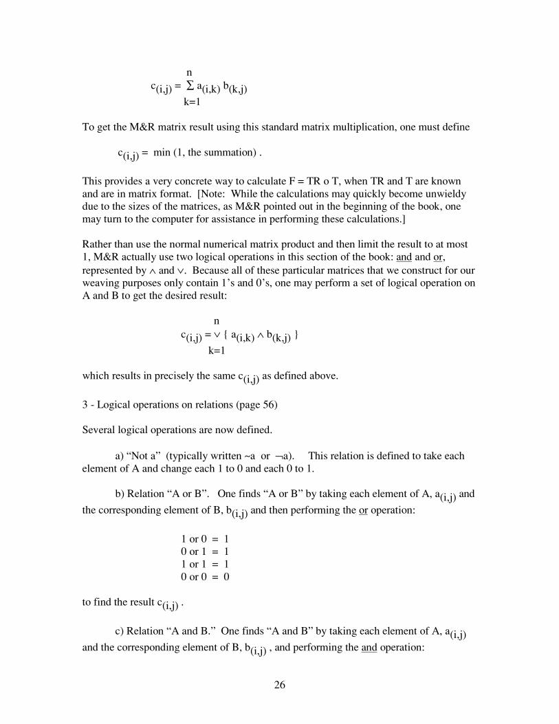
26
n c(i,j) = ∑ a(i,k) b(k,j)
k=1
To get the M&R matrix result using this standard matrix multiplication, one must define
c(i,j) = min (1, the summation) .
This provides a very concrete way to calculate F = TR o T, when TR and T are knownand are in matrix format. [Note: While the calculations may quickly become unwieldydue to the sizes of the matrices, as M&R pointed out in the beginning of the book, onemay turn to the computer for assistance in performing these calculations.]
Rather than use the normal numerical matrix product and then limit the result to at most1, M&R actually use two logical operations in this section of the book: and and or,represented by ∧ and ∨. Because all of these particular matrices that we construct for ourweaving purposes only contain 1’s and 0’s, one may perform a set of logical operation onA and B to get the desired result:
n c(i,j) = ∨ { a(i,k) ∧ b(k,j) }
k=1
which results in precisely the same c(i,j) as defined above.
3 - Logical operations on relations (page 56)
Several logical operations are now defined.
a) “Not a” (typically written ~a or ¬a). This relation is defined to take eachelement of A and change each 1 to 0 and each 0 to 1.
b) Relation “A or B”. One finds “A or B” by taking each element of A, a(i,j) and
the corresponding element of B, b(i,j) and then performing the or operation:
1 or 0 = 10 or 1 = 11 or 1 = 10 or 0 = 0
to find the result c(i,j) .
c) Relation “A and B.” One finds “A and B” by taking each element of A, a(i,j)and the corresponding element of B, b(i,j) , and performing the and operation:
27
1 and 0 = 00 and 1 = 01 and 1 = 10 and 0 = 0
to find the result c(i,j) .
SECTION C REPRESENTATION TYPE “Treadling - Tie-up - Threading” (page 59)
This section explores the case of the fabric draft where the tie-up shows each treadle tiedto several shafts with only one treadle used at a time in the treadling sequence. Therelevance of the tie-up to provide separate structural information is discussed.
Chapter One - Definition (page 59)
1 - Fabric Draft Formula (page 59)
When the draft was defined using a direct tie-up (one treadle to one shaftcorrespondence), then the fabric drawdown is F = TR o T where TR is the treadlingfunction and T is the threading function (page 13). Now, M&R show how the tie-up actsas intermediary between the threading shafts and the treadles tied to multiple shafts.
To find F when each treadle is tied to multiple shafts, M&R first convert the tie-up andtreadling back to a pegplan type treadling with a direct tie-up. They show that the
pegplan (PP) is PP = TR o (TU)-1 where TU is the tie-up. M&R note that the fabricdesign can be determined by looking at the treadling sequence and the associated shafts.They note that here the tie-up plays the role that the threading performed in the previousfabric calculation.
The phrase “plays the role” means that when you look at the order of the individualcomponents in the formulas, you can infer that one variable is acting like another based
on its position in the formula. Since PP = TR o (TU)-1 and also F = TR o T, then if PPand F both somehow represent the same design, by comparing these two equations one
can see that the TU-1 and T are in the same relative position. This means that the tie-up(inverse function of, in this case) plays the role of the threading. M&R do a lot of this“positional” comparison throughout the remainder of Part One. It’s also interesting tonote that this approach allows programs that are set-up to do only drawdowns to performother weaving related computations.
Putting this all together yields the new F (new, for the case of not having a direct tie-up):
28
F = TR o TU-1 o T.
2 - Compatibility of Representation (page 61)
M&R show that when the tie-up is direct (and therefore TU = I), then the previousformula (F = TR o T) holds. Henceforth, they will assume that there is not a direct tie-upin the weaving draft, and they use the more general formula developed in the previoussubsection. They note the cases where the tie-up is direct.
Chapter Two - From representation type “treadling - tie-up - threading” to “pegplan -straight tie-up - threading.” Multiple draft of fabric. (page 62)
Using the results of the previous chapter, M&R create a new draft layout that shows bothversions of the draft (direct tie-up/pegplan type treadling and complex tie-up (not directtie-up), non-pegplan type treadling) on a single diagram. M&R call this a multiple draft.[Note: On page 62, there is a shaded area below the threading and above the draft. It isshaded -- to show it is not used -- although from the picture it looks like there are straightlines of twill threading.]
M&R warn the reader that none of the calculations inferred by this multiple diagram isrequired to give valid results. (These calculations have not yet been explained.)Therefore, the reader must exercise some care when reading a multiple draft. Insuccessive paragraphs, they walk the reader through the calculations that fit each space inthe multiple draft and show the reader that just one calculation yields nonsense: the oneusing the four spaces on the bottom left of the multiple draft (page 64). As M&R pointout, this calculation is correct only if TU is a function or is injective.
M&R suggest that instead of doing successive calculations, the calculations can be re-grouped on a single diagram and a single computation performed. Thus, the fabric draft
F = TR o TU-1 o T. If TR, TU, and T are represented by matrices, a computer can beused to perform the calculations.
SECTION D FIRST PRACTICAL CONSEQUENCES OF THE FABRIC FORMULA
Chapter One - Another Representation of the fabric draft (page 67)
This chapter examines a weaving draft where the draft’s pegplan (with direct tie-up) hasbeen rewritten: the pegplan is flipped over on its side and placed in the tie-up position ofthe draft, and the draft’s treadling order is replaced with a reversed direct treadling orderrepresented by I. The pictures on page 68 make clear how the pegplan is rotated into this
position and it is mathematically denoted (PP)-1, or the inverse of the PP matrix
representation. M&R show that when this (PP)-1 replaces the tie-up function and I (the
29
identity function) replaces the treadling function, then the same drawdown results. [Note:This section is nothing but mathematical manipulations to show how one can rewrite thetreadling and tie-up without impact to the fabric drawdown. However, this is a usefultextile designer’s tool to show an entire, rather than partial, design with a representationthat is wider than high.]
Chapter Two - Geometric Transformation of a Draft (page 69)
This chapter is a review of the information presented earlier (Part One, Section B,Chapter 2, subsection 13, page 50). [Note: The M&R reference is incorrect.] There is nonew information here, but the mathematical representation is a little different than before,where symmetries were looked at with respect to the first ( I ) and second (-I ) diagonals.
The first paragraph might more easily be read as follows:
“The fabric formula F = TR o (TU)-1 o T allows us to quickly generalize the alreadyobtained results (first part, B13) on the fabric draft. We can reflect a rectangular tie-upusing horizontal symmetry, using vertical symmetry, or using a 180 degree rotation. Aslong as we apply judicious symmetry to the threading, treadling, or both, we can assurethere is no change to the fabric.”
Chapter 3 - Warp and Weft Exchange (reversal) in a Fabric (page 71)
This chapter looks at turned drafts. M&R use, as an example, overshot.
The process of turning a draft results in using (TR)-1 as the threading, (TU)-1 as the tie-
up, and T-1 as the treadling. Mathematically, this yields a drawdown that is symmetricwith respect to the first diagonal of the original drawdown. M&R note that this turnedovershot draft example results in a summer and winter threading and that a summer andwinter fabric can be turned to be an overshot pattern.
Chapter Four - Zooming in on the Tie-up (page 73)
M&R continue to manipulate the math developed previously. They look at the case of astraight-draw threading, direct treadling, where all of the draft complexity is in the tie-up.They show mathematically and with an illustration that the resulting design drawdown is
exactly (TU)-1, or, the pattern created by the tie-up’s mirror image with respect to thefirst diagonal. [Note: the design is the reflection of the tie-up, not its “reverse.”]
They show that expanding the threading and treadling also causes the pattern to beexpanded, but with paver-edge contours rather than curves. Finally, M&R take a profileblock design and substitute a unit weave structure that is unnamed (but appears to besummer and winter) to show a completed fabric design with computer generateddrawdown.

30
Chapter Five - Generated Fabric (page 74)
M&R begin this chapter by noting a difference in approach between the way a fabricdesigner works and the way a computer software program works. [Note: The computersoftware program is probably POINTCARRE′; not all weaving software works this way.]M&R state that the designer begins with a motif or design and then creates the requiredthreading and pegplan. M&R state that, on the other hand, a computer program usesinformation contained in the pegplan and threading to generate the design and drawdown.
Mathematically, the equation F = TR o T can be manipulated to have the design (F) aspart of a calculation to generate the required treadling. M&R show the math required toproduce the result:
TR = F o T-1 .
Remembering from before that
F = TR o (TU)-1 o T,then
TR = F o T-1 o I.
By association of the terms in these equations, this says that the pegplan is the design onegets using the original threading as a tie-up and the original design as the treadling. Ifeach is represented by a matrix, the calculation of the composite function quickly yieldsTR, or the pegplan that one is seeking. Thus, they prove that the pegplan can becalculated from the fabric design and threading.
The second part of this chapter addresses the converse of the above, asking whether ornot F′ = TR′ o T ? M&R show that this, in general, is not true. However, they showthat F′ ⊆ TR′ o T, or in words, if one uses the approach described above to derive apegplan and then uses that pegplan with the original threading, the resulting fabric will bea “superset” of the desired fabric. They further comment that this technique is of interestbecause it allows the automatic generation of multiple fabrics from a single threading.They conclude this chapter with an example based on the method of designing with aninitial, from Part Three.
Chapter Six - Symmetrical Fabrics in Connection with the First Diagonal (page 78)
1 - “Treadled as threaded” Representation type (page 78)
As a reminder, this threading axial of Brandon-Guiget was considered previously in PartOne, Section B, Chapter 2, subsection 9b on page 44. The reader saw that with a direct
31
tie-up, the treadling is T-1 and the resulting drawdown of the fabric contains the firstdiagonal ( I ).
Now, M&R consider the case where the tie-up contains the diagonal ( I ) but is not just adirect tie-up. Rather, the tie-up includes shafts tied to treadles in addition to the shaftstied to the treadles required for a direct tie-up. They show that the drawdown issymmetric with respect to the first diagonal if and only if the tie-up is symmetric withrespect to the first diagonal. This is proved by assuming symmetry in the drawdown
(F = F-1) and by showing that this implies TU = (TU)-1 .
Several examples of this follow. Then, M&R state that they will take on the systematicstudy of all treadlings that, for a particular threading, produce a design containing the firstdiagonal.
[Note: unfortunately, there are several errors on page 78:
F = F-1 ⇔ T x -1 o TU x -1 o T = ( T-1 o (TU) -1 o RT-1
should be F = F -1 ⇔ T -1 o TU -1 o T = (T -1 o (TU) -1 o T) -1 . ]
2 - Condition for a design to be symmetric with respect to the first diagonal (page 80)
This section contains a great deal of math. It poses the question: if we start with athreading T, can we find a treadling TR such that the resulting design is symmetric withrespect to the first diagonal? M&R show, through manipulation of relations, that if one
has a treadling of the form T-1 o B, where B is a symmetric relation, then one obtains thedesired design. [Note: B can be any symmetric relation. M&R don’t show a specificexample of B, as they provide a general proof of this relationship between the threadingand treadling.]
M&R state that later on they will show that B is actually a relation that tells the designer
how to get from T -1 to the treadling. They conclude this subsection by stating that adesign that is symmetric with respect to the first diagonal can be considered ageneralization of “treadled as threaded.”
3 - Practical Consequences (page 82)
M&R give a four block based design to demonstrate the previous conclusions. Inaddition, they use a previous result that a “treadled as threaded” design can berepresented as:
F = T-1 o B-1 o T.

32
When one replaces B with B-1, one then recognizes that B plays the role of the tie-up.This relationship holds because B is symmetrical. [Note: This goes back to M&R’stechnique recognizing that different elements of the draft play the role of threading,treadling, or tie-up based on their position in the fabric equation or in the multiple draftdiagrams.]
Thus, to get all possible symmetric drawdowns for this block design, one must find allsymmetric block tie-ups. M&R do this for the four block design shown on page 82.[Note: The horizontal and vertical lines which separate the drawdown from the threading,tie-up, and treadling are missing in the draft shown on the bottom of page 82.]
There are a total of ten (10) block design tie-ups, symmetric with respect to the firstdiagonal of the original block design tie-up. [Note: Recall that a function that has thissymmetry property is also called involutive. M&R use that word here, but it reallydoesn’t add any clarity to the discussion.] On page 83, the ten block design drawdownsthat correspond to the block design tie-ups are provided.
33
PART TWO - TRANSFORMATION BASES
Now that a mathematical model of the basic draft has been established, M&R willdevelop some tools that allow a weaver to go from a freely drawn design to a completeddrawdown.
SECTION A THEORETICAL STUDY (page 85)
This section of the book begins by looking at and organizing tools. In the following,M&R look at various ways to design by transposing the threading. This is done either bychanging the order of the shafts or by putting the threads of many shafts onto one shaft.With another tool, the designer can separate threads from one shaft onto many othershafts. The relative arrangement of the warp ends will remain the same.
Chapter One - Transformation conserving the draft dimension. Amalgamation. (page 85)
M&R note that for a variety of reasons, but in particular to solve the friction problemsthat sometimes accompany a densely sett warp, weavers may need to change how theythread the warp on available shafts. This may include mixing the shaft assignments forthe threading, which can obscure the design view on a written draft. M&R say that theextra work required to carefully study the threading and construct various alternatives isnegligible, thanks to modern computer-based weaving tools.
1- Rearrangement Bases (page 85)
First, a rearrangement base is defined. In non-mathematical terms, this is a threadingorder that may create a re-arranged threading, treadling, and/or tie-up. In mathematicalterms, this is a bijection, B, which when combined with the original threading relation, Tgives a new threading T′. (Mathematically, one would say B is composed with T.) Thefirst illustrated examples show this rearrangement (also called transposition). Topreserve the design, the same shafts cannot be raised, so the tie-up or treadling mustchange. A new tie-up is shown, developed from the threading and design. Next, M&Rshow mathematically what is probably intuitively obvious to a weaver: if the shafts of thetie-up are rearranged exactly the same way as they are rearranged for the threading, thenthe fabric drawdown is unchanged. [Note: On the top of page 87, where TU′ = b o TU, itshould be written TU′ = B o TU. Also, on page 86, all of the (-1) notation should bechanged to “-I.”]
2 - Amalgamation (page 88)
The goal of amalgamation of a threading is to maximally separate the shafts on whichthere are adjacent threads. [Note: in chemistry, amalgam means a solution of a metal inmercury. It is not easy to separate the metals in an amalgam, once mixed together. Thus,
34
amalgamated weaves are combined weaves that generally lose their (in this case visual)individual identities in the process of being combined.]
M&R provide an example of how to transform one specific threading to another onewhich has maximum separation. They note that this process only changes the threadingand tie-up, but that the treadling is unchanged. The solution uses the same shafts in thesame order, but skips the warp ends two-by-two onto even numbered and then unevennumbered shafts. The amalgamated threadings and tie-ups are shown for the original andthe rearranged orders. This amalgamation results in a separation of at least one shaftbetween warp ends.
With the 8 shaft example given on pages 88-89, M&R show how to organize in a regularmanner a cyclical association of shafts. The maximum separation is provided by the satinweave, which binds each end as far away as possible from any other end. With 8 shafts,the separation between shafts is 5. This is shown for both arranged and for satin-basedamalgamated threading drafts and tie-ups. On an amalgamated satin base, the graphicdefinition of the resulting threading draft is completely broken and the design illegible.The treadling remains intact and is easily followed: a welcome point for handweavers.
While M&R note this is a good technique for handweavers, they point out that in thetextile industry, one normally works with the pegplan rather than the threading. Thismotivates their examination of another amalgamation technique.
3 - Multiple Draft of Amalgamation (page 90)
M&R go back to the Part One concept of the multiple draft (page 62-64), in which draftsare drawn together to show the effects of successive applications of the original fabricequations:
F = TR o T
or (for a non-direct tie-up): F = TR o (TU)-1 o T.
[Note: One might think of calculations on the multiple draft as iterative operations.Using the 4 sections of the draft which together make up the 4 corners of a rectangle,compute F = TR o (TU)-1 o T for one of the 4 areas in which 3 of the “corners” havecomplete information. Then, using that completed calculation as one of the 4 “corners”of another rectangle, again use F = TR o (TU) -1 o T to calculate whichever one “corner”is unknown. Continue as needed to get the information needed.]
M&R show by calculation that if the threading is changed by a transformation base B,then one can achieve the same fabric drawdown as before by altering the pegplan so that
if the original pegplan is PP, the new one is (PP)′ = PP o B-1. Using the validcalculations of the multiple draft shown on page 92, M&R show that the fabricdrawdown is unchanged (invariant) when the new threading (B o T) and new pegplan
(PP o B-1) are used, together.

35
4 - Equivalent Drafts (page 44)
The two threadings, T and T′, are said to be equivalent because there is a bijection Bwhere T′ = B o T .
Similarly, the two tie-ups TU and (TU)′ are defined to be equivalent. [Note: Thesedefinitions are used in the following sections.]
Chapter Two - Transformations lessening the draft dimension. Telescoping (page 95)
M&R introduce the techniques described in this chapter by posing the followingquestion: how does a weaver adapt a curve requiring 48 shafts to a 12 shaft loom?
They propose two kinds of solutions:
- digitizing, which reduces the vertical dimension of the curve, but whichintroduces a stair-step looking curve on the preserved design; or
- telescoping, which slices the original curve into sections which are then“stacked”, and which preserves the original curve but adds harmonics thatinterfere with the clarity of the design.
The first solution examined is the technique of digitizing. Using a 48 shaft example,M&R map sets of 4 shafts to one shaft, thus reducing the shaft requirement from 48 to12. This is explained by example. Then, they define a relation B which maps 4 shafts ofthreading T to one shaft of a threading T′. M&R note that B is a function, but it is notinjective (one to one); for example, shafts 1 and 2 of T are mapped to shaft 1 of T′. Thus,B is not bijective, either. One can apply this same method to the treadling and tie-up aswas applied to the threading to reduce the 48 shaft draft’s treadling and tie-up to a 12shaft draft’s treadling and tie-up. One can see the results of this in the right hand figureon the top of page 97. The threading and pegplan would then yield the weaker, stair-stepped digitized curve shown at the bottom of the page. A lengthy mathematicaldescription is provided to determine the new tie-up, which turns out to use the threadingaxial of B. All calculations result in the digitized multiple draft on the bottom of page 99. Now, M&R begin the discussion of telescoping (page 100). They start by reminding thereader that a straight connection reproduces the draft. Thus, they decide that to reproduce4 slices of 12 shafts, they will use a straight base of 12 shafts, repeated 4 times. Thisbecomes the telescoping threading base, pictured on the top of page 101. The axial ofthis 12 shaft telescoping base is calculated (top, page 101) with the straight threading anddirect tie-up of the required 4 treadling repeats. The tie-up (associated with the
augmented pegplan and threading) is calculated from B-1 o B, which is also called thethreading axial of B. (This definition has been previously provided on page 98). Thetelescoping base applied to the original 48 shaft curve results in the telescoped 12 shaft

36
curve shown on the bottom of page 100. Harmonics are defined here as the parasitesintroduced as a result of telescoping. These seem to “vibrate around the original curve.”M&R state that the choice of a particular telescoping base impacts the separation ofdesign area from background area. They note that one can use the harmonics either toemphasize or to hide the design curve. Chapter Three - Transformations increasing the draft dimensions. Draft combinations.(page 102) M&R, at the start of the chapter, pose a challenge to the reader after they note thefollowing: 1 - a straight draw can produce a large variety of fabrics, but the size of the repeat
is limited to the number of shafts of the loom; and 2 - a complex threading can produce a fabric with a large repeat, but all treadlings
produce fabrics that resemble each other. The challenge: how to create a single threading that has a large repeat yet can be wovento create two very different looks? The remainder of this chapter looks at combining two different threadings into onethreading, which is then capable reproducing all arrangements of the two originalthreadings. On page 103 and following, M&R provide a recipe for combining two threadings. [Note:American handweavers will recognize this as a “blended draft.”] The techniquedescribed is a “brute force” technique that requires a total number of shafts equal to theproduct of the number of shafts required for each of the two threadings being combined.M&R show how mathematically one can transform each of the original threadings withan appropriate transformation base to get the desired combined threading (pages 105-107). On page 108, M&R note that it is frequently possible to combine threadings on fewershafts than the product of the shafts used by the two threadings. The more commonalitybetween the two threadings being combined, the fewer number of shafts required by thecombined threading. SECTION B PRACTICAL STUDY OF TELESCOPING Telescoping is one of two methods used to reduce the number of shafts required by aparticular weave design. It requires properly applying a transformation base to the draftto produce a new threading, tie-up, and treadling from the original.
37
M&R introduce two drafts on which the rest of the discussion is based. The first draft,top left of page 109, has the outlines of two circles in the drawdown portion of the draft.The second draft, top right of page 109, has two filled circles in the drawdown area.M&R call the first “an ensemble of lines” (a line graphic) and the second “a surfaceopposition” (a surface graphic). Chapter One - Telescoping bases (page 109) Depending on the choice of a transformation base, telescoping creates various harmoniclines around the original design elements. In the succeeding sections, M&R show severalexamples of this. All of the examples in this chapter are based on the line graphic draftprovided on the left, page 109. 1 - Straight Bases (page 110) [Note: The definition of a telescoping base and methods of calculating the tie-up, newthreading, and drawdown are explained on pages 95 - 101.] The first base introduced is a straight base -- so called because the base threading is a“straight draw.” Five examples are given, in which the original 48 shaft draft is reduced,in order, to 24, 16, 12, 10, and 6 shafts. In each case, M&R show the new draft. Fromthese examples, M&R make the following points:
- the original design is not modified by telescoping on a straight base becausethe base axis has an uninterrupted diagonal (which becomes part of the designcurve as the number of shafts is reduced); and
- as the number of shafts is reduced by telescoping, a proportional increase inthe number of harmonic lines appears around the original design curve.These telescoping harmonics are the lines that are parallel to the originalcurve; and
- the telescoping base used does not have to be (numerically) a factor of theoriginal number of shafts. For example, 10 is not a factor of 48. [Note: Theword less-multiples would more properly be sub-multiples or factors. Afactor of a number is any number which divides the original number evenly --with no remainder.]
2 - Straight bases and twill bases (page 112) M&R give an example of a telescoping base with a mixture of straight and broken twills.The harmonics are modified by changing the curve reduction lines to broken twill lines.The harmonics then are cast perpendicular to the design curve rather than left parallel tovibrate at the edge of the curve.

38
3 - Straight and amalgamated bases (page 112) M&R give two examples of telescoping bases built from satins, illustrating how theharmonics are very blurred and without an obvious order. The third example of thissection is based on a telescoping base comprised of a broken twill. To break-up the orderly graphic definition of harmonics, M&R choose two telescopingbases. These bases break the order of interlacing to blur or obliterate the harmonic lines.The first example combines skip twill bases of satins on 12 ends, skipping 5 and 7. (Thisis similar to the bases of amalgamation.) The second example combines a skip twill basesatin on 12 ends, skipping 7, and a derivation of a satin, also on 12 ends but binding onends adjacent to the skipped 7 binding ends. The third example, which uses a brokentwill base, again illustrates the freedom of the designer to create modified, less intenseharmonic lines when using this shaft reduction method. 4 - Interfering bases (page 113) In this section, M&R provide some examples of interfering or broken twill bases to showhow these bases telescope the number of shafts while minimizing the resultingharmonics. Interfering bases are two or more bases interleaved and used together as a single base. Ifused separately, each base has a different impact on the original design drawdown. Whenput together, depending on the nature of the bases, the original design drawdown can bemore or less obscured by harmonics. The minimization of harmonics of the interferingbase curve is dependent on two characteristics of the bases being interleaved:
- if the number of threads in the two series of warp ends defining the bases are relative primes, then there will tend to be good dispersion of the harmonics; and- the bases used can be straight bases or amalgamated bases.
M&R show by example that two straight bases used together have different effectsdepending on whether or not they are relative primes. [Note: The text uses the words“primary within themselves” rather than the more customary phrase: relative primes.Two numbers are relative primes if they have no common factor. Thus, 7 and 9 arerelative primes. However, 10 and 6 are not relative primes: they share the common factorof 2.]
When the bases combined are straight bases which are relative primes, then M&R showthat the resulting design drawdown has more clarity -- the harmonics are somewhat betterdispersed. This is shown by example, not mathematically.
39
5 - Telescoping bases: application to digitization (page 115)
This section contains three examples showing that the choice of a telescoping base can bea way to change the scale of the design curve. As one would expect, a “blockier” lookingtelescoping base results in a “blockier” looking telescoped design.
In the three examples, the telescoping base used is printed in bold face under the multiplefabric draft for the first two examples, and to the left for the third example. (It’s also inits usual position within the multiple fabric draft.)
Chapter Two - Telescoping Surfaces: notion of relative freedom (page 117)
This chapter focuses on telescoping bases that help to physically distance “the cloud ofharmonics” from the original design curve. M&R use the surface graphic design draftfrom the right, on page 109 in the examples of this chapter.
1 - Notion of “relative freedom” (page 117)
This term comes from authors Brandon-Guiguet (The Initials Methode, A MathematicalAspect of Weaving with Shafts, 1938, the book which M&R used as a basis for thiswork). It is a number that is calculated on the telescoped draft, and it is the shortestdistance between two threads from the base of a single shaft. In the diagram, one seesthat several squares have been drawn; the number n is the number of shafts between 2threads, counted along the right or left side of a square (illustration, middle of page 117).
2 - Comparing different telescoping bases (page 117)
M&R begin this section by pointing out that a straight telescoping base provides thelargest relative freedom (or separation of the original design from the harmonics resultingfrom telescoping). They provide an example of the surface graphic design reduced from48 shafts to 24 shafts, using a 24 shaft straight base. The circle forms which appear in thetreadling area result in the creation of harmonics that are tangent to the circles.
In the examples that follow, M&R show some different approaches to isolate the originaldesign from its telescoping induced harmonics. They show that an interfering base (thesame base as on page 114) leaves a relatively large relative freedom, unlike anamalgamated base. Why? Because with a straight base, the telescoped circle designs areisolated from but overpowered by the harmonics (which now have mass equal to the massof the circle design area). Twill and amalgamated bases are dismissed as being too weakrelative to the base number of shafts. However, an interfering base adequately blurs theharmonics and yet has a relative freedom only slightly less than the base number of shaftswhen both series are near equal in size. The example of a telescoped interfering baseshows a true zone of harmonics distanced from the ring surface and overall design clarity.

40
Chapter Three - Discussion: digitization and/or telescoping (page 119)
This chapter is a summary of the digitizing and telescoping techniques presented in PartTwo, Section B. M&R base their conclusions on more examples that use the surfacegraphic design drafts defined before.
Four multiple drafts are used to repeat points previously made: that the choice of thetelescoping base impacts the visual effect of the original design due to the harmonicswhich result from telescoping (bottom two drafts on page 119). The two drafts on the topof page 120 show the effects of digitizing and telescoping (left example) or just digitizing(right example).
These four examples lead M&R to make the following statements:
- reserve the use of telescoping to line drawings (designs which depend on lines);
- a uniform surface effect can be achieved on curves which are digitized enough so that during the process of applying a weave structure to the design, no telescoping is needed to further reduce shaft numbers.
Further, M&R state that effort should be spent on reducing the stair-step look of curveswhen choosing a weave structure for the design: the threading (of the weave structure)selected should be one which helps “round off” the curves, whenever possible.

41
PART THREECONTEXTURIZING
The authors are now ready to apply all the background of Part One (themathematical representation of the threading, treadling, and tie-up) with Part Two (howto modify the draft elements) to show how one can create new designs by combiningsome elementary weaves that provide contrasts between pattern areas and backgroundareas. M&R use the word contexturizing to describe the process of converting a particulardesign into something that can be woven (i.e., producing a weave draft), using one ormore weave structures (armures) to distinguish pattern from background. In general,M&R state that the relationship between the design and the number of shafts required toweave it depends on the weave structure(s) chosen.
M&R provide textile designers with three fundamental approaches to designing:using block threadings transcribed onto the design curve, using weave structures as thebasis of a network onto which the design curve is placed, and using a synthesis of thesetwo approaches. The synthesis is using block design methods in sequence with networkdesign methods, varying the order of applying the various techniques, to obtain a varietyof results.
SECTION A BLOCK METHOD (page 125)
Designing and weaving with blocks allows the weaver much flexibility. It is acompromise between an ideal design line and the limits of how a design can beimplemented on a loom. The authors state that they will show the essential rulescommon to a group of traditional structures (e.g., overshot, summer and winter, andtwills) that will allow creation of new combinations that can be used when designing andweaving with blocks. Knowing the traditional rules of arrangement will allow thedesigner to create new combinations. That knowledge will extend the richness ofindustrial designs on a few shafts beyond the opposition of warp and weft effects becausethese traditional drafts typically are not threaded on a straight draw. The handweaver, inturn, can use these traditional weaving structures in designing fabrics with more than onebasic weave structure on one draft.
M&R note that getting complex designs on looms with small numbers of shafts requiresusing non-straight threadings. [Note: M&R repeatedly state that textile designers usestraight threadings, and then vary the tie-up and treadling to achieve the desired design.]
Chapter One - Seven Examples (page 125)
This chapter begins with the definition of a four block profile, where each of the fourblocks corresponds to one shaft (Block A to shaft 1, Block B to shaft 2, Block C to shaft

42
3, and Block D to shaft 4). The profile tie-up blocks are arranged for a straight draw, andthe profile treadling blocks’ order is “tromp as writ” or treadled as threaded.
1 – Contexturizing on 16 shafts (page 126)
This section introduces some of the methods of block profiling. It includes a definition ofblocks in the tie-up and treadling portions of the profile. [Note: The terms I use to refer tothese are profile tie-up blocks and profile treadling blocks. The threading and drawdownportions of a block profile are referred to as the profile threading blocks and profiledrawdown, respectively.] This technique is applied with traditional thread arrangementsand also with a combination of elementary weave structures.
Specifically, this section looks at a way to associate the previous four block profiledesign with a 16 shaft weaving draft. M&R present the following formula: four shaftsare assigned to each profile threading block, with no shafts shared between blocks. Thus,one threading block in the previous block profile design is now replaced with four shafts,threaded in numerically increasing sequence. For example: Block B corresponds to block #2 in the block profile design, so Block B is threaded on shafts 5,6,7,8.
Similarly, each block in the profile’s treadling sequence is replaced with 4 picks and 4treadles (in this example).
The illustrations on page 126 show that this first example of contexturizing a blockprofile uses a weave structure that has two different faces (the structure selected can bewoven as either warp-faced or weft-faced, providing two strongly contrasting-in-appearance weaves).
The contrasting faces are used to define the draft’s tie-up. [Note: The terms I use to referto the items that replace profile components and define a weaving draft are blockthreadings, block treadlings or treadling cells, and tie-up cells.] Two tie-up cells areshown, one providing a warp faced cloth on four shafts and one providing a weft facedcloth on four shafts. (American weavers will recognize this as false satin, or brokentwill.) These tie-up cells, each four by four in size, are then carefully combined witheach other to control float lengths at their boundaries, and then they are positioned in theoriginal profile tie-up. Each block in the profile tie-up is replaced with one of the tie-upcells. The dark blocks shown in the profile tie-up show the structure used to weave thedesign, and the uncolored areas in the profile tie-up when replaced with a specific tie-upcell show the structure used to weave the background. In this example, each block of theprofile’s tie-up is replaced by the (4 square by 4 square) tie-up cell that provides a warp-faced cloth, and all other areas of the block profile tie-up are replaced with the (4 squareby 4 square) tie-up cell that provides a weft-faced cloth. An illustration that shows howthese two tie-up cells can be arranged with each other is provided on the top of page 128.
This contexturizing provides a 16 shaft draft which has structural integrity, as itsindividual elements are all structurally sound.

43
The phrase “the enigma of limitations” refers to the potential problems at the boundariesof the block profile’s threading and tie-up blocks, during the contexturizing process. Theauthors show that the tie-up cells must be arranged relative to each other in a way thatpreserves a sound weave structure at their boundaries. These tie-up cells are referred toas “armure cells” by M&R.
There are many possible extensions in contexturizing. The authors note that one may usea twill structure (woven as a 3/1 versus 1/3 twill, or woven as a 2/2 right hand versus 2/2left hand twill) or basket weave structure versus plain weave structure, etc., whenplanning the tie-up cells. They caution that care must be exercised at all the joins of allthe tie-up cells used in order to preserve the overall integrity of the resulting fabric (i.e.,the design line definition is maintained and the floats are controlled in length).
Other extensions are illustrated. The first example uses a different 4 shaft tie-up cell. Thetwo contrasting tie-up cells used to distinguish pattern from background are shown underthe resulting 16-by-16 tie-up on page 129. The second set of extensions uses tie-up cellswith larger repeats. The complete draft appears on the top of page 130, with thedrawdown enlarged on its right. Another example in the middle of page 130 proposes aneven more complex tie-up cell.
The summary for this section notes the following: if one starts with four independentdesign blocks arranged in a block profile, then one can be certain of a sound fabric if oneproperly arranges the tie-up and threading cells associated with the selected weavestructure.
Further, M&R state that:
- the extension of the original profile threading blocks is unlimited when thestructure chosen for the threading cells provides manageable floats;
- the extension of profile treadling blocks is unlimited when the chosen weavelimits the length of warp floats with its structure; and
- the placement of the tie-up cells in the profile block tie-up is totally free as long as binding thread control is done correctly in the tie-up cells.
2 – Contexturizing on 12 shafts (page 131) This section examines the process of contexturizing the original four block profile designon 12 shafts. This time, each of the four profile threading blocks is assigned to exactlythree shafts (Block A: shafts 1-3; Block B: shafts 4-6; Block C: shafts 7-9, and Block D:shafts 10-12). Then, the previous process is used except that the weave structure chosen is a three shafttwill. The two contrasting areas are achieved using 2/1 twill tie-up in each tie-up cell that
44
replaces each block (pattern) of the profile tie-up, and a 1/2 twill in each tie-up cell thatreplaces each blank (background) of the profile tie-up. The essential point is that thereare fewer choices of weave structures than with 16 shafts, since there are fewer 3 shaftweaves than there are 4 shaft weaves. This reduction does not reduce the graphicaccuracy of the design. But with fewer intersections in the selected weave structure(three shaft twill), there is less difference between the warp/weft opposition, and thusdifferences between the pattern and background areas are less obvious. The same three properties with the same join conditions hold for the 12 shaft example asfor the 16 shaft example. [Note: these properties are restated in a slightly different orderand with slight variations from before.] These properties hold as long as binding threadcontrol is done correctly in the tie-up cells:
- profile block size can be extended without limit in warp and weft; - the tie-up cells can be dispersed freely; and
- the block arrangement in the threading and treadling can be freely performed. M&R note that this freedom is a result of careful choice of the tie-up cells. 3 – Contexturizing on 8 shafts (page 133) This section again uses the four block profile design presented at the beginning of thechapter. M&R state that there are two ways to design on 8 shafts:
- using 4 groups of 2 shafts with no shared shafts between profile threading blocks; and- using 4 groups of 4 shafts, with 2 shafts shared between 2 adjacent profile threading blocks.
For the first, Block A uses shafts 1,2; Block B uses shafts 3,4; Block C uses shafts 5,6;and Block D uses shafts 7,8. With two shafts assigned to each profile threading block,the choice of weaves is very constrained: plain weave is the only structure that canprovide unlimited extension of blocks in both warp and weft (threading and treadling).With any other structure, the resulting warp or weft floats limit the possible extensions ofthe threading. Also, blocks of other structures may not be regrouped without controllingthe limitations at the boundaries. M&R give four examples based on the original fourblock profile using a plain weave block threading and the following four opposingweaves: plain weave with warp floats, plain weave with weft floats, plain weave withbasket weave, plain weave with huck (or false leno) effect. Regrouping or rearrangingadjacent blocks with some tie-up cells can only be done by controlling the binding points. In the next example, there is a graphic showing warp rep on a plain weave ground. (Thecorresponding tie-up cells are shown on the right of the draft tie-up, on the top of page
45
134.) Expanding the warp rep at the expense of the plain weave ground would riskrapidly loosing join opposition and, therefore, design line clarity. The opposing weaverepeat shown is comparable to huck, or, for the textile designer, mock leno. The samerep expansion limitation is obvious. [Note: there are no examples provided for, or discussion of, the second design techniqueidentified in the beginning of this section: 4 groups of 4 shafts, with 2 shafts sharedbetween 2 adjacent blocks. Also note that M&R use the phrase “tabby” when Americanweavers generally use the term plain weave. American weavers often use the word tabbyto refer to the alternate picks thrown, which weave plain weave, in supplementary weftweaves.] 4 – Contexturizing on 6 shafts (page 135) In this section, the same four block profile design is used to introduce designing withdependent blocks. The weave structure summer and winter introduces block threadingsthat have 2 shafts in common. M&R point out that with just six shafts, the blockthreadings (not the profile threading blocks) must share some shafts if each blockthreading is to use at least 2 shafts. M&R present the tied unit elements of blockthreadings and then a draft showing the tie-up and treadling. They point out that thefabric foundation is plain weave woven with tabby picks alternating with the patternpicks. The binding ends in the block threading allow unlimited extension of the profilethreading blocks, arranged in any order. At the end of this section, a different substitution is made: shafts 1 and 2 are “tiedtogether” and considered as one in the tie-up. Thus, each block threading uses 2 shafts: 1binding and one pattern, rather than the previous approach which used two binding andone pattern shaft per block threading. M&R point out that there are now constraints onthe profile blocks’ extension and arrangement, similar to those seen in the example on 8shafts. 5 - First Contexture on four shafts (page 138) Here, the number of shafts is equal to the number of blocks in the original four blockprofile design. M&R note that this number of shafts will result in several constraints inthe design process. Overshot is introduced as a traditional structure using two shafts per profile threadingblock: Block A uses shafts 1,2; Block B uses shafts 2,3; Block C uses shafts 3,4; andBlock D uses shafts 4,1. In this case, one must be careful to maintain the sequence ofodd/even shafts, and also to exercise caution in defining the tie-up especially whennonadjacent blocks are used together in sequence (e.g., Blocks B and D). Three tie-upoptions are given for this example: - plain weave (balanced warp and weft), - two of each block’s shafts raised (warp effect), and

46
- two of each block’s shafts lowered (weft effect). Then, M&R state that this four block example is unique because on four shafts, the onlypossible twill is 2/2 twill. In the following draft analysis, it is noted that when weaving overshot a binding weft andpattern weft are used. In the threading, however, there are no binding threads. Thus:
- there is limited extension possible in the profile threading blocks due to the need to control weft floats, and on four shafts one cannot weave two blocks simultaneously; [A weaving note: on four block overshot, when weaving one block as pattern, two blocks weave as half-tones and one weaves as background.]- there is unlimited extension of profile treadling blocks if alternate weft shots create tabby; and- there is limited extension of the profile treadling blocks if there are no alternating tabby picks woven, in order to bind warp floats.
6 - Second Contexture on 4 shafts (page 140) This section looks at using the crackle weave structure in the four block profile design.In this case, the profile threading block assignments are: Block A uses shafts 1,2,3; BlockB uses shafts 2,3,4; Block C uses shafts 3,4,5; and Block D uses shafts 4,1,2. M&R note that in crackle two blocks always weave together because two ends arecommon to two adjacent blocks. This is stated as a drawback. However, an advantage ofthe crackle weave is that the blocks based on 3 shafts can be extended in both thethreading and treadling without causing a float problem because the ends always alternateon even and odd shaft numbers. M&R note that the original four block profile design ismodified because no single block can be woven separately from all other blocks. 7 - Third Contexture on 4 shafts (page 142) In this last transformation of the original four block profile design to a stable weavestructure, M&R achieve a shadow weave effect through use of two colors in both warpand weft. The following profile threading block assignments are made: Block A usesshafts 1,3; Block B uses shafts 2,4; Block C uses shafts 3,1; and Block D uses shafts 4,2.The same 2/2 twill tie-up is used as before, and the profile treadling blocks use the sameshafts as the profile threading blocks. Two diagrams are shown on page 142: the top one reflects warp and weft, with bothalternating black and white color threads. The bottom diagram, with solid dark warp and(unmarked) all light weft, is used to reveal the real structure of the fabric (which isobscured by the alternating colors in the top drawdown).

47
The authors note that while plain weave is the basic weave structure, there is a two threadfloat where blocks change. Both profile threading and treadling blocks can be extendeddue to the plain weave structure. The drawdown shows the pattern developing from thecolor and weave effects rather than from structure. Chapter Two - Creating New Arrangements (page 143) First, the authors present a summary based on the previous chapter’s examples. 1 - Summary of Properties (page 143) The examples of the preceding chapter provide evidence for the following rules:
- reducing the number of shafts per profile block results in fewer choices ofweave structures that can be used; and
- if shafts are common to two or more of the profile threading blocks, then there are restrictions in arranging the blocks.
Block threadings can be arranged as follows:
- if one defines a group of threads for each block in a profile threading so that there are no shafts common to the blocks, then:
-- when the number of blocks = (number of shafts) / 4 , then: there are four shafts available per block. -- when the number of blocks = (number of shafts)/3 , then: there are three shafts available per block. -- when the number of blocks = (number of shafts)/ 2 , then: there are two shafts available per block.
- if one defines a group of threads for each block in a profile threading so that there are only binding shafts in common between blocks, then:
-- when there are two binding shafts, then: number of blocks = number shafts – 2, and there are 3 shafts per block. -- when there is one binding shaft, then: number of blocks = number shafts – 1, and there are 2 shafts per block.
- if one creates a threading with independent blocks that have common pattern shafts, and
-- number of blocks = number shafts, and there can be two shafts per block -- number of blocks = number shafts, and there can be three shafts per block.
48
The authors remind the reader that there are restrictions regarding extending profilethreading blocks and rearranging blocks in the profile tie-up. 2 - Creating new arrangements (page 144) M&R note that the previous seven examples are not an exhaustive list of all possibleblock threadings. They offer two techniques (and give several examples of each) forgenerating additional threading arrangements based on using independent blocks anddependent blocks. a) Independent block threadings (blocks with no pattern shafts in common) (page 144) Using a concrete six shaft example, M&R give several techniques for modifications to ablock threading so that it can be extended, repeated, and support several choices of weavestructures. The following are provided as suggestions: a1 - add two binding threads between blocks to allow for rearranging blocks
a2 - add two binding threads per block threading cell to allow for unlimitedextension a3 - add a binding thread in the manner of the summer and winter unit weave tosave shafts while keeping the properties of the profile design a4 - change the number of binding threads per pattern thread (e.g., use 2 for 1) toallow weft patterning on a plain weave ground a5 - add one shaft between pattern threads to eliminate the extension andrearrangement properties a6 - add another shaft for a separate binding thread between the block threadings(threading cells) of a5 to provide extension and rearrangement properties.
The properties of independent blocks are:
- since there are no pattern shafts common to blocks, any block profile design(continuous or not) can use these block threadings;
- when block threadings don’t have common shafts, there can be any arrangement of tie-up cells; and- when block threadings do have common shafts, then the arrangement of the
tie-up depends on how adjacent blocks are arranged in the profile design. b) Dependent block threadings (adjacent blocks with common pattern shafts) (page 146) Using the same concrete example (on six shafts), two techniques are suggested to reducethe number of shafts required:
b1 - each block threading shares a pattern shaft with its adjacent block, and thethreading alternates with that shared pattern shaft, allowing one to weave a repweave, thereby getting 4 blocks of pattern; and
49
b2 - all block threadings are based on a three thread cell, comprised of the patternthread and the threads on the shafts on each side of the pattern thread. Theseblocks weave in pairs, since there are two shafts common to adjacent blocks. Thisthree end unit allows unlimited extension with no increase in the number ofrequired shafts. Regrouping blocks is not possible. [Note: the text phrase “twocommon blocks” should be “two common shafts” in the last line of page 146.]
When one uses dependent block threadings, there are constraints in the arrangement ofthreading, tie-up, and treadling blocks. As previously stated, on four shafts the tie-up cellchoices are limited to 2/2 twill or fancy twills having 2 warp ends raised or 2 weft endsnot raised. The same limitation of long floats also affects the tie-up cell rearrangementsof 8 shaft dependent block designs. Generally, only non-adjacent blocks of at least threeshafts can be tied on the same treadle. M&R provide 5 simple twill tie-ups for 8 shafts. Choice of threading and treadling Dependent block threadings (block threadings with common pattern shafts) can only beused in profile designs with a continuous curve (no jumps or breaks). The transformationof a block threading onto a non-continuous curve results in tie-up constraints that maymake some block groupings impossible. That will depend on the specific arrangement ofblocks and the lengths of floats where threads on the same shafts occur in adjacentblocks. If within the block treadling cells there is an inherent binding, then the block treadlingcells can be freely rearranged without regard for a specific order. 3 - How to choose an arrangement (page 148) The authors emphasize the importance of early selection of the block threading to be usedin a particular block profile design. This selection determines three important designfactors: the number of shafts needed, the maximum number of blocks possible, and,consequently, the number of lines on which the digitized design curve must be written.[Note: It appears that the word “curve” is misplaced on the graphic on page 148. Theword “curve” should be moved to the right and printed under the words: “definition ofthe digitized ______” .] This choice of block threading is made with respect to the type of design line desired andalso the overall design effect desired. There are two overall design effects mentioned: (1)pattern created by a line or lines on a background (e.g., like that achievable withovershot, a fancy twill, or summer and winter), and (2) pattern created by areas of twocontrasting weave structures. For the first, the pattern formed on a ground cloth, M&Roffer two types of design for consideration: a line based design on a solid ground and afilled-area design on a solid ground. In the line design, it is the lines themselves thatform the pattern making up the overall design. In the filled-area design, it is the filled-inareas that form the pattern areas making up the overall design. For a line based design,
50
M&R state that adjacent blocks don’t need to be rearranged. For a filled-area baseddesign, blocks must be able to be extended and/or rearranged as necessary to achieve thedesired look. For the second design effect, it is the opposition of two weaves and the associatedtextures that separate the pattern area from the background area. The ideal choice is twoweaves whose block threadings and tie-up cells can be arranged to join by opposition.This join achieves the strongest clarity of the graphic line along the boundary betweenfigure and ground. M&R state that the two weaves selected (one for the background, onefor the design area) should be compatible, and that the structures should have acompatible take-up. This section and chapter conclude with the authors’ saying that weavers should maintainthe design line, even when using a small number of shafts, at the expense of thestructure(s) chosen in the block threading(s). They state that this technique is well suitedto all designs based on block threadings that have either a plain weave structure in theblock threading or pattern ends alternating with binding ends (i.e., a tied weave). Chapter 3 - Telescoping Threadings in Blocks (page 149) As a summary of the telescoping process, M&R remind the reader that they havereservations on how well telescoping works for the design effect: “filled-area designbased patterns.” However, they say that with a well-defined curve, it’s good for thegraphic line designs. Then, they remind the reader that telescoping (because it involvesmanipulating the transformation base) rearranges the elements of the block threading.Thus, depending on how the telescoping is done, one ends up with a varying ability toarrange the resulting blocks. A bad telescoping can completely alter the overall fabricstructure. 1 - Telescoping independent block threadings (page 149) In this section, telescoping is only considered for independent block threadings that haveat least one shaft separating them. There are no constraints on reordering (or regrouping)these blocks. Thus, for independent blocks, the following applies: - any telescoping base may be used. When there are no pattern shafts common between two or more block threadings, then: - telescoping can be performed for the original curve. An example follows. A curved block design requiring 24 blocks is transformed into a 28shaft summer and winter weave using the tools of the previous chapter. (The summerand winter structure used here has four binding threads, so 24 pattern + 4 binding = 28shafts.) Then, a telescoping base is chosen which does not change the binding (so 4 shaftsare still required to perform that function). But the threading line that was obtained in the

51
first process has been changed through telescoping to a 16 shaft threading line (12 patternplus 4 binding). M&R point out that if the above two steps are reversed (first telescope the design line,then transform it to a summer and winter weave with 4 binding threads), one ends upwith exactly the same 16 shaft result. 2 - Telescoping a threading with dependent blocks (page 151) Due to the constraints of floats in dependent block threadings (see previous chapter), onlystraight line telescoping is possible. (M&R point out the need to use continuousfunctions for telescoping in these circumstances, which a straight line definitely is!) a) Telescoping the threading M&R point out that just as for the previous example one can either first telescope or firsttransform the block profile design using the selected block threading(s). With the sametelescoping base, one ends up at the same end point. On the bottom portion of page 151, a 24 block profile design is shown. It is telescoped to12 shafts, then a threading applied (top path) and alternately, a block threading is appliedwhich is then telescoped to 12 shafts (bottom path). In both cases, the same endpoint isreached: a block threading on 12 shafts. There is some inconsistent language used in thediagram describing this process. b) Telescoping the tie-up and treadling Telescoping is always done on a straight tie-up. A straight (or direct) tie-up is usedbecause a weave base in the tie-up is destroyed or its elements are regrouped by thetelescoping process. Using a single design curve to make their point, M&R show that onemust perform telescoping on the profile tie-up blocks and profile treadling blocks prior tocontexturizing the design with the choice of particular block threadings and treadlings. c) Example of non-straight line telescoping A non-continuous design curve results from a threading line telescoped on a straight baseand then amalgamated. M&R provide an example of telescoping performed on a designcurve, using a non-linear telescoping base. They state (without proof) that if thetelescoping base respects the order of even and odd numbered shafts (this guarantees atleast three shafts between two adjacent blocks), then one can still select block threadingsfor the resulting non-continuous design curve to produce a woven design. In the particular example used, M&R note that the telescoping harmonic lines andadditional secondary harmonic lines break the juxtaposition of warp/weft effects. Thesebroken graphic lines further weaken the pattern lines of overshot. The parallel primaryand secondary harmonic lines and broken design lines greatly reduce interest in this type
52
of non-straight line telescoping. [Note: this is, of course, a matter of opinion and dependson what your goal is. If you want clean design lines, you won’t get them with thisapproach.] M&R show (via example) that if one first transforms the block profile design to a blockthreading based on a particular weave structure, then telescope this block threading with anon-linear telescoping base, the overall integrity of the weave structure is lost. Thus, they decide to limit themselves to first performing straight line telescoping,followed by transformation of that telescoped block profile design to a block threading. 3 - Conclusion (page 155) M&R state that the design curve on a fabric is the result of a treadling cell acting on athreading cell. With independent design blocks, all telescoping can be performed either before or afterthe design blocks are transformed with block threadings. All other block profile designs require that telescoping be performed prior to insertingblock threadings, unless one uses a straight-lined telescoping process. M&R remind the reader to avoid use of telescoping for the surface effects based designs(isolated from the fabric). Instead of telescoping, one should digitize the original designcurve, and then transform the design profile using independent block threadings havingno common shafts. SECTION B METHOD OF DRAFTING ON A NETWORK (page 157) Common to all the methods of designing using block profiles (Section A), one finds thatthe minimum building block (or cell) is a two warp ends/two weft picks set of threads.However, in this section M&R present another method of designing, attributed to workdone earlier by Brandon and Guiget in their 1938 book Methode des Initiales. Thismethod places a design curve on a network, thus achieving a graphic resolution of onewarp/one weft. Rather than placing a weave structure onto a design curve (which is thegeneral process of designing with blocks), one places the design curve onto a weavestructure which repeats as an initial across a network.. Chapter One - The Network (page 157) M&R define an initial for a network in the first sentence of this chapter. It is a threadingrepeat (or group of threads) from which one can create two or more weaves that are, insome way, opposites. These opposite weaves include:

53
- weft emphasis vs. warp emphasis, for the same weave structure (e.g., 1/3 and
3/1 twill);- two different (visually) weaves based on the same threading (e.g., a twill threading which can be woven to produce two very different designs); and
- two different weave structures (e.g., a fancy complex weave vs. plain weave). An example of the second type of “opposition weaves” is given on the bottom of page157. In the example, the threading repeat is 24 threads on 6 shafts. M&R state that thisthreading repeat can be used as the initial of a network, by repeating it both in height andwidth. Although any threading repeat could be an initial, M&R point out practical conditionsthat an initial must meet:
- it should generally be built using 2 to 8 shafts, or it will graphically dominatethe design itself (if there are fewer than 24 shafts used);
- it is not limited in length, but very elaborate initials may affect the precisionof curves in a design; and
- the initial cannot contain groups of shafts reserved for binding ends. (If itdoes, then the vertical stacking of the initial to create a network will beproblematic.)
M&R recommend selection of an initial that allows for strong color contrast in warp andweft, or strong contrast in textures, which is hard to achieve when the design is based onblock threadings. An illustration (page 158) shows a threading repeated in height andwidth to form a network along with the initial. Chapter Two - Building a curve on a network and the properties of this curve (page 159) Curves are created on a particular network by overlaying the design curve (“theoricthreading”) on the network. The threading curve is defined by the places where a pointon the design curve coincides with any point on the network. If a point on the designcurve does not intersect a point on the network, then the closest network point to it isused for the threading. As in a regular threading draft, there is only one point in anycolumn but there may be many points per row depending on the design curve and thenetwork. This is shown in a diagram on the middle of page 159. The diagram shows theinitial (top right corner), the design curve (top, solid stepped-line), the network based onthe initial (lightly colored points), and the curve (darkly colored points) overlaid on thenetwork. Curve Properties on a Network (page 159) 1 - M&R show that for a networked curve, repeating units of the base weave in thetreadling produces the same fabric as the one obtained by using the treadling from this

54
initial’s networked weave repeat. They show this for the original networked curve aswell as for the networked curve, telescoped from 21 to 6 shafts. 2 - Weaving a networked curve with its original treadling results in a transition zonebetween the original design area and its background. Keeping both of these properties in mind allows one to define two or more structures tobe used in the treadling, which will not only differentiate the woven design from itsbackground, but will also eliminate undesireable floats at the design/backgroundboundaries. This can be done by choosing simple weaves compatible with the initial andusing the weave(s) versus its opposite(s) for distinguishing the pattern area versus thebackground area. M&R direct the reader to follow the rules of damask and then providesix examples of these opposites on page 161. Chapter Three - Linear Initial (page 162) M&R define a linear initial to be a straight threading repeat. It therefore is always squarebecause the number of shafts is equal to the number of warp ends in the initial. Thisrelation defines the period of the network. The linear is the easiest initial to work with,they state. All threadings built on the linear initial are able to reproduce all the weaveunits in the treadling draft, as long as these weave units are the same size as the initial. In the example on the top of page 162, they give the example of a five end linear initialusing the opposite 5 end satin weaves shown on page 161. The point is that with the fiveend initial, the fabric will be joined correctly at the boundaries between the design andbackground because the satins are compatible with the initial, and use of these oppositesensures control of floats. 1 - Method of building a threading on one network (page 162) This section shows the relationship between the digitized curve, the number of shaftsneeded, and the period of the network. The example is for a linear initial, but the methodalso applies to a nonlinear initial. M&R start with a curve defined on 12 shafts. To make the curve the same thickness asthe network period of 5 (that is, the length of the initial), one must add four more pointsto each point on the 12 shaft curve. This produces a curve of width five, needing now12 + 4 = 16 shafts. Graphically, the result looks like the stroke of a paint brush. Whenplaced on top of the network, the brush stroke intersects (or coincides with) the points ofthe network only once for each column. M&R propose the general rule: definition of the curve (how many shafts it can use) = number of shafts available - period of the network + 1
55
Two examples are given on page 163. On the top example, a curve has been reduced to13 shafts via digitizing. To put it on a network of period 4 (the initial is a twill of lengthfour) requires a total of 16 shafts ( 13 = 16 - 4 + 1). Similarly, the second example looksat a curve reduced to 9 shafts, but placed on a network based on an 8-end initial. Thisrequires 16 shafts (9 = 16 - 8 + 1). M&R conclude that the choice of the base weaves and, therefore, of the initial (four oreight end, in the two examples) affects the accuracy of the curve if the number of shaftsone has to work with stays the same (in this case, 16). In the note on the top of page 164, M&R propose an alternative to a networking designproblem: the progressive deterioration of the design curve (due to an initial size whichmay force up the number of shafts needed and create weak lines without mass). Theiralternative to digitizing the original curve to fewer shafts is to telescope the resultingnetworked curve to the necessary number of shafts. An example of a networked curve,first digitized and then telescoped, appears on the bottom of page 164. This alsoillustrates the design’s surface degradation caused by telescoping networked curves. 2 - Evolution of the surface limits as a function of the initial (page 165) This section provides three examples of design degradation caused by increasing thenetwork period (or size of the initial) while holding all else (number of shafts, treadling)constant. It appears the period is increased from 4 to 6 to 8 in these examples. One canobserve the decreased definition of the curve as the network period is increased. Two points are made with the top example:
- in building a profile threading, a strong block effect (or stair-step look)detracts from the original curve; and
- in building a networked threading, the size of the initial most affects theoriginal curve and causes blurred edges, even when the one-shaft reduction ismaintained.
The second example points to the matter of scale. M&R point out that if the graphicscale needs to be increased, it is best to do this by means other than by extending theinitial period. However, if the designer maintains an initial of eight for large designrepeats, the transition float zone between the figure and the background will not beincreased. The third example shows the reverse of this: the period is doubled from theprevious example, and the graphic definition is so vague that there is little scale.
M&R state that as a general rule, one should avoid using initials of size equal to orgreater than eight except for large repeats (a threading or treadling repeat greater than200), or when one wishes to have the resulting effects as part of the design.
56
3 - The threading gradient: positioning large repeats (page 166)
This section looks at ways to change the scale of a design. M&R remark that as part ofthe design process, one frequently expands the original design.
To change scale with block profiles:
- changing a theoretical threading (i.e., a block profile design) to a practicalthreading always introduces a scale change. (Each element of the theoreticalthreading is replaced with a set of at least two threads, warp and weft.)
- larger changes in scale can be made by expanding blocks. (If a unit weave isbeing used, threading blocks can be repeated. Or, one may use a larger threadingblock substitution, such as a 16 thread/block Bateman weave rather than a fourthread/block twill weave. [Note: This last is my example, supplementing M&R’swords.] )
To change scale using a networking initial:
- there is no scale change when converting a theoretical threading to a practicalthreading on a network: each “thread” of the theoretical threading (or designthreading) corresponds to exactly one point on the network.
- changes in scale can be made by positioning the curve on a larger networkrepeat: the curve is expanded, lengthened.
On the bottom of page 166 M&R give an example that shows a curve expanded in bothwarp and weft. They note that the transition zone between the background and designareas does not change when the scale of the curve is changed, because the network initialis kept constant. The transition area is extended in the warp direction when the treadlingcurves are expanded.
Cases of the straight-draw type threading (page 167)
M&R give three examples of scale changes that result just from changing the gradient ofa twill threading. They remind the reader that frequently designers prefer working with astraight threading for the versatility it provides: simply by changing the treadling, oneobtains significant design changes in the fabric.
4 - Comparing a block threading and a network threading (page 168)
At this point, M&R feel the reader understands how implementing a curve with an initialcompares to implementing the same curve with blocks. [Note: “implementing” is usedhere to mean change from a theoretical design threading to a weaveable or practicalthreading.]
57
An example is given to demonstrate the differences. In summary, using blocks keeps thedesign “clean”: there is no transition zone, but the design itself is impacted. Themodified curves are blocky. Using an initial results in a better preserved design, but thecost is introduction of a transition zone between the design and the background, whenwoven.
Chapter Four - Curve telescoping on an initial network (page 169)
This chapter looks at curves that are not telescoped on a network (built on a particularinitial). However, if the curve needs to be telescoped to fit on fewer shafts while keepingthe weave structure consistent with the network’s initial, then the telescoping base mustbe one that will not alter the network.
1 - Choice of telescoping base (page 169)
For a telescoped curve to be written on a network whose initial is length n, then M&Rstate that it suffices to use a telescoping base built on the straight initial network of size n.[Note that this section refers to a straight initial, which is the same thing as a linearinitial.]
An example of this is provided on page 169. In the middle of the page, the telescopingbase is drawn (based on 16 shafts). Then, a draft shows the corresponding treadling for astraight tie-up. A multiple draft (bottom right) shows the telescoped curve (original curveis bottom left). By looking very carefully, one can see that the weave structure’s“opposites”, in this case 3/1 versus 1/3 twill, are preserved. One can also see theharmonics introduced due to telescoping.
M&R state that when a curve is built on a complex network (one which does not use astraight initial) the telescoping base must still be built on a straight initial of the sameperiod (length). A second example is provided on page 170. This example shows a 13end telescoping base built on a five end straight initial.
2 - Relative freedom and secondary initial (page 171)
Telescoping a curve with a base that preserves the network and the weave structure(previous section) restricts the weaver’s ability to control the harmonics. M&R state thatin most cases, one is forced to use telescoping bases built on a network where the period(length of the initial) is less than the primary initial and a factor of the primary initial.This type of telescoping results in a new network. That new network’s initial is called asecondary initial.
With the creation of a secondary initial, M&R pose the question: what is left of the weavestructures that were used with the primary (original) initial? Recall that the telescopingbase introduces an area of harmonics whose width, measured from any part of the
58
original draft, is equal to the relative freedom of that telescoping base. Within this area,the characteristics of the primary initial network hold.
M&R provide an example of this on the bottom of page 171 to top of page 172. Theyremind us that interfering bases assure a good dispersal of harmonics while maintainingoptimum relative freedom. They note that interfering telescoping bases built on a straightinitial of two are very useful when telescoping curves on networks based on 4, 6, or 8 endinitials. A final example is given on the top of page 173.
3 - Positioning on a network precedes telescoping (page 173)
M&R begin this section by reminding the reader that when using independent threadingblocks, the blocks themselves can be telescoped prior to substituting them into a blockprofile.
However, when working on a network, positioning the curve on the network alwaysprecedes telescoping. M&R point out that the act of telescoping creates a more complexthreading and treadling, and it is very difficult to select a set of weave structures thatwould work well in the treadling. Two examples point out some of the difficulties at theend of the section.
4 - Conclusion, and how to telescope a threading on an initial network (page 174)
The following summary statements are made:
- the threading placement onto a network always precedes telescoping;- if the telescoping base used is built on a straight (linear) initial the same length as the primary initial, then the secondary network will be the same as the primary network;- if the telescoping base used is built on a straight initial whose length m is a factor of the primary initial length n, then the second network is built on an initial resulting from telescoping the primary initial;- the relative freedom of a telescoping base keeps a harmonic zone between the design and background areas which allows continued use of the weave structures built on the primary initial’s network. Interfering telescoping bases are particularly effective;- telescoping a network threading is useful to highlight lines or brushstrokes
while maintaining a good definition of the design; and- in order to telescope small surface effects without having the design obscured
by the weave structures chosen, one must use a telescoping base that has asmaller relative freedom.
59
SECTION C SYNTHESIS ESSAY (Summary) page 175
M&R state two goals of this synthesis of designing with blocks and initials:
- to summarize, using a organizational scheme, the various ideas from Part Three; and
- to suggest some areas needing further research.
Chapter One - Schematic of synthesis: a decision helper (page 175)
This section makes use of the example first defined on page 160. [Note: on the followingtwo pages, it is easiest to see what is being presented if the reader can match the lines onthe right edge of page 176 with the lines on the left edge of page 177. This can be doneby making a photocopy of one of these two pages.]
Starting at the middle left margin of page 176, M&R show various options for generatinga weaving draft from the 48 shaft block profile design shown. Each of the six resultsshown uses the techniques described in Part Three. The top three results are all digitized,and one is placed on a network. The two on page 177 have no harmonics but also give apoor definition of the two circles. The bottom three have better curve definition, but alsohave harmonics introduced due to telescoping.
Chapter Two - Examples of studies (page 179)
M&R state that the examples given heretofore adhered closely to the rules beingexplained. The “block method” and the “initial method” were not well integrated (witheach other) for the sake of giving the reader a clear explanation of each. However, M&Rnote that these two approaches are not exclusive of each other. They can and should becombined to create more original designs that are not tarnished with an overly technicalappearance.
The six examples that follow are meant to inspire the reader to use the techniques learnedin this book in creative ways. M&R discuss the three elements that the designer mustreflect on to form design curves: design features (use of design areas and lines), scale ofthe design, and the interactions of different weave structures.
GENERAL CONCLUSION (page 183)
M&R repeat and give emphasis to conclusions stated previously. They speculate aboutthe reason more weavers did not use the initial method earlier this century, when it wasfirst defined by Brandon and Guiguet. They note that the various stages of design oftenhave small conflicts with each other that the designer’s judgement must resolve. Theyleave the reader with their wish that further work be done and shared, using thesemethods.

60
Related Documents