1 A major PROJECT REPORT ON “ national HIGHWAY CONSTRUCTIONS” Under guidance of (External Examiner) (Internal Examiner)

Welcome message from author
This document is posted to help you gain knowledge. Please leave a comment to let me know what you think about it! Share it to your friends and learn new things together.
Transcript

1
A major PROJECT REPORT
ON
“ national HIGHWAY CONSTRUCTIONS”
Under guidance of
(External Examiner) (Internal Examiner)

2
INTRODUCTION
In a National Highway project, the engineer
has to plan, design and construct either a
network of new roads or road link.
Once a highway is constructed, development takes
along the adjoining land and subsequent changes in

3
alignment in geometric standards become very
difficult. A badly aligned highway is not only a source
of potential traffic hazard, but also causes a
considerable increase in transportation cost and
strain on the drivers and the passengers. Therefore,
proper investigation and planning are most important
in a road project, keeping in view the present day needs
as well as the future development of the region

4
NATIONAL HIGHWAY
PROJECT
DEFINITIONS
In the contract the following words and
expressions shall have the meanings here by
assigned to them, except where the context
otherwise requires:

5
(i) A BOLLARD is a short vertical post typically
found where large ships docks. While originally
it only meant a post used on a quick for mooring,
the word now also describes a variety of
structure to control or direct road traffic. The
term may be related to bole, meaning the lower
trunk of a tree.
(ii) A BYEPASS is a road or highway that avoids or
“bypasses” a built up area, town, or village, to
let through traffic flow without interference
from local traffic, to reduce congestion in the
built up area, and to improve road safety.
If there are no strong land use controls,
buildings are built a bypass, converting it into an
ordinary town road, and the bypass may
eventually become as congested as the local
streets it was intended to avoid.

6
(iii) A CURB or KERB is the edge where a raised
pavement/footpath, road median, or road
shoulder meets an unraised street or other
roadway. Typically made from concrete,
asphalt, or long stones, the purpose is twofold:
first as a gutter for proper drainage of the
roadway, and second for safety, to kee p
motorist from driving into the shoulder, median,
sidewalk, or pavement.
(iv) “EMPLOYERS” means the person named as
such in part II of these conditions and the legal
successors in title to such person. But not any
assignee of such person.
(V) “CONTRACTOR” means the person whose
tender has been accepted by the employer and
the legal successors in title to such person. But
not any assignee of such person.
“Contract” means the conditions, the
specification, the drawings, the bill of
quantity, the tender, the letter of

7
acceptance; the contract agreement and
such further documents as may be expressly
incorporated in Letter of Acceptance or
Contract Agreement.
“Specifications” means the specification of
the work included in the contract and any
modification therefore or addition.
“Drawings” means all drawings,
calculations and technical information of a
like nature provided by the Engineer to the
contractor under the contract and all
drawings, Calculations, Samples, Pattern,
Models, Operations and maintenance,
manuals and other technical information of
a like nature submitted by the contractor
and approved by the Engineer.
“Bill of Quantities” means the priced and
completed bill of quantities forming part of
tender.

8
“Section” means a part of the works
specifically identified in the Contract as a
section.
“Site” means the places provided by the
Employer where the works are to be
executed and any other places as may be
specifically designated in the Contract as
forming part of the site.


10
The contractor shall establish working Bench
marks tied with the reference Bench Mark in the
soon after taking possession of the site. The
reference Bench Mark for the area shall be as
indicated in the contract document of the values
of the same shall be obtained by the Contractor
from the Engineer. The working bench mark
shall be at rate of 4 per km and also at or near
all drainage structures, over bridges and under
passes. The working Bench Mark/levels should
be got approved from the Engineer. Check must
be based on this Bench Mark once every month
and adjustments, if any, got agreed with the
Engineer and recorded. An up-to-date record of
all Bench Mark including approved adjustments,
if any, shall be maintained by the contractor and
also a copy supplied to the Engineer for his
record.
The lines and levels of formation, side slopes,
drainage works, carriageways and shoulders
shall be carefully set out and frequently

11
checked, care being taken to ensure that
correct gradients and cross sections are
obtained everywhere.
In order to facilitate the setting out of the
works, the centreline of the highway must be
accurately established by the contractor and
approved by the engineer. It must then be
accurately referenced in a manner satisfactory
to the engineer, every 50m intervals in plain and
rolling terrains and 20m intervals in highly
terrain and in all curve point as directed by the
engineer, with marker pegs and chainage boards
sets in or near the fence line, and schedule of
reference dimensions shall be prepared and
supplied by the Contractor to the Engineer.
These markers shall be maintained until the
works reach finished formation levels are
accepted by the Engineer.
On construction reaching the formation level
stage, the centre line again be set out by the
contractor and when approved by the Engineer,
shall be accurately referenced in a manner

12
satisfactory to the Engineer by markers pegs set
at the outer limits of the formation.
No marker pegs or markers shall be moved
without the approval of the Engineer and and no
earth work shall be commenced until the centre
line has been referenced.
The contractor will be the sole responsible
party for safeguarding all survey monuments,
bench marks, etc. The Engineer will provide the
Contractor necessary for setting out of the
centre line. All dimensions and levels shown on
the drawing or mentioned in documents forming
part of the or issued under the contract shall be
verified by the Contractor on the site and he
shall immediately inform the engineer of any
apparent error in such dimensions. The
Contractor shall in connection with the staking
out of the canter line, survey the terrain along
the road and shall submit the engineer for his
approval, a profile along the road centre line
and cross section at intervals as required by the
Engineer.

13
After obtaining approval of the engineer, work
on earthwork can commence and the profile and
cross section shall from the basis for
measurements and payments.
The work of setting out shall be deemed to be a
part of general works preparatory to the
execution of work and no separate payments
shall be made for the same..


15
TEST ON SUB GRADE SOIL
(I) GRAIN SIZE ANALYSIS
INTRODUCTION:
Most of the method for the soil identification
and classification are based on certain physical
properties of the soil. The commonly used
properties for the classification are the grain
size distribution liquid limit and plasticity index.
These properties have also been used in
empirical design method for flexible pavement;
and in deciding the suitable of sub grad soil.
Grain size analysis also known as mechanical
analysis of soil is the determination of the
percent of individual grain size present in the

16
sample. The results of the test are of great
value in soil classification. In mechanical
stabilization of soil and for designing soil
aggregates mixture the result of gradation test
are used .correlation have also made between
the grain size distribution of soil and the
general soil behavior as the sub grade material
and the performance such as susceptibility to
frost action, pumping of rigid pavement etc.also
permeability characteristics, ‘bearing capacity
and some other properties, are approximately
estimated based on grain size distribution of the
soil. The soil is generally divided into four parts
on the particle size. The fraction of the soil
which is larger than 2.00 mm size is called
gravel, between 2.00 mm and 0.06 mm is sand
0.002mm silt and that is smaller than 0.002 mm
size is clay. Two type of sieves are available, one
type with square perforation on plate to sieves
course aggregate and gravel, the other type
being mesh sieves made of woven wire mesh to
sieves finer particle such fine aggregate and
soil fraction consisting of sand silt and clay.

17
However the sieves opening of the smallest mesh
sieves commonly available is about 0.075 mm,
which is commonly known as 200 mesh sieves
therefore all soil particle consisting of silt and
clay which are smaller than 0.06 mm size will
pass through the fine mesh sieves with 0.075 mm
opening. Therefore the grain size analysis of
course fraction of soil is carried out using
sieves the principle of sedimentation in water.
The sieves analysis is a simple test consisting of
sieving a measured quantity of material through
successively smaller sieves. The weight retain
on each sieves. The weight retain on each sieve is
expressed as a percentage of the total sample.
The sediment principle has been used for finding
the grain size distribution of fine fraction; two
methods are commonly used pipette method and
the hydrometer method.
The grain size distribution of soil particle of size
greater than 63 micron is determine by sieving
the soil on set of sieves of decreasing sieve

18
opening placed one below the other and
separating out the different size ranges.
APPARATUS:
Various apparatus set of standard sieves of
different sieves size, balance, and rubber
covered pestle mortar, oven, riffle, sieves
shaker.
Procedure
For the fraction retained on 2.0 mm sieves.
Sufficient quantity of dry soil retained on
2.0 mm sieves is weighed out. The quantity of
sample taken may be increased when the
maximum size of particle is higher. The sample
separated into various fraction by sieving
through the set of sieves of size100, 63, 20,
6, 4.75, and 2 mm is sieves. After initial sieves,
material retained on each sieves carefully
collected and weighed.
For fraction passing 2.0 mm sieves and
retained on 0.63 mm size.
19
The required quantity of soil sample is taken
by riffling or quartering method, dried in
oven at 105 to 110 c and is subjected to dry
sieves analysis using a set of sieves with
sieves opening 2.0, 0.6, 0.425, 0.15, and 0.075
mm, pan lid. The material collected on the
each sieves and on the pan are separately
collected and weighed.
CALCULATION:
The weight of dry soil fraction retained on each
sieve is calculated as a percentage of the total
dry weight of the sample taken. The gravel, sand
, silt ,and clay contain in percentage.
RESULT:
The gravel, silt sand clay contents are marked
as result.


21
(II) CONSISTENCY LIMITS &
INDICES
The physical properties of fine grained soil,
especially of clay differ much at different
water content. Clay may be almost in liquid
state, or it may snow plastic behavior or may be
very stiff depending on the moisture content.
Plasticity is a property of outstanding
importance for clayey soil, which may be
explained as the ability to undergo changes in
shape without rupture.
22
Liquid limit it may be defined as the minimum
content at which soil will flow under the
application of a very small shearing force. The
liquid limit is usually determined in the
laboratory using mechanical device.
Plastic limit may define in general term, as
minimum terms, as minimum moisture content at
which the soil remain in a plastic state. The
lower limit is arbitrarily defined and determined
in the laboratory by prescribed test procedure.
Plastic index is defined as the numerical
difference between the liquid and plastic limit.
p.i thus indicates the range of moisture content
over which the soil in plastic condition.
Consistency limit and plasticity index vary for
different type. Hence properties are generally
used in the identification and classification of
soil
LIQUID LIMIT TEST:
23
Liquid limit is the moisture content at which 25
blow in standard liquid limit apparatus will just
close a groove of standardized dimension cut in
the sample by grooving tool by a specified
amount.
APPARATUS:
Mechanical liquid limit device consists of a cup
and arrangement for raising and dropping
through a specified height, grooving tool. Other
apparatus include spatula, moisture containers,
and balance of capacity 200g sensitive to0.01 g
oven to maintain 105 to110c.
PROCEDURE:
About 120 g of dry pulverized soil sample
passing 425 micron sieve is weighted, and mixed
thoroughly with distilled water in the
evaporating dish to from a uniform thick paste.
The liquid limit device is adjusted to have a free
fall of cup through 10mm.a portion of the paste

24
is placed above the lowest spot, and squeezed
down with the spatula to have a horizontal
surface . the specimen is trimmed by firm strokes
of spatula in a such a way that the maximum depth
of soil sample in the cup is 10 mm. the soil in the
cup is divided along the diameter through the
center line pf the cam followed by firm strokes
of the grooving tool. So as to get a clean and
sharp groove. The crank is rotated at the rated
at the rate of two revolutions per second by
hand so that the cup is lifted and dropped. This
continued till the two halves of the soil cake
come in to contact at the bottom of the groove
along a distance of 10 mm, and the number of
blows given is recorded . a representative soil is
taken, placed in moisture container, lid placed
over it and weighed. The container in dried in
oven and the dry weight determined the next day
for finding the moisture content of the soil. The
operations are repeated for at least three more
trial with slightly increased moisture content
each time, nothing the number of blows so that

25
there at least four uniformly distribute reading
of number of blows between 10 and 40 blows.
CALCULATION:
the flow index The flow cure is plotted by taking
the number of blows in the log scale on the x-
axis, and the water content in arithmetic scale
on the y-axis, of format sheet .the flow curve is
straight line drawn on semi-logrithmetic plot.
The moisture content corresponding to 25 blow
is read from this curve rounding off the nearest
whole number and is reported as the liquid w1 of
the soil. The slope of the straight line flow cure
is flow index. It may be calculated from the
following formula;
For index, If= 𝑊1−𝑊2
𝐿𝑜𝑔 𝑛2−𝐿𝑜𝑔𝑛1 =
𝑊10−𝑊100
𝐿𝑜𝑔10 100/10 =w𝑊10 −
𝑊100
26
Hence if the flow curve is extrapolated and
moisture w10 and w100 corresponding to
10and 100 blows respectively are found, then
the difference in these water content would
give of the soil.
PLASTIC LIMIT TEST
Plastic limit is the moisture content at which a
soil when rolled in to thread of smallest
diameter possible, start crumbling and has
diameter of 3 mm.
APPARATUS:
27
Evaporating dish, spatula, glass plate, moisture
containers, rod of 3 mm diameter , balance
sensitive to 0.01 g, drying oven controlled at
temperature 105 to110c.
PROCEDURE:
About 20 g of dry, pulverized soil passing 425
micron IS sieve is weighed out. The soil is mixed
thoroughly with distilled water in the
evaporating dish till the soil paste is plastic
enough to be easily molded with fingers. A small
ball is formed glass plate to a thread. The
pressure just sufficient to roll into a thread of
uniform diameter should be used. The rate of
rolling should be between 80 and 90 strokes per
minute counting a stroke as one complete motion
of hand forward and back to starting position
again. The rolling is done till the diameterof thread is 3
mm . then the soil is kneaded together to a ball and
roller again to from therad this process of
alternate rolling and kneading is continude
untill the thread. This process of alternate

28
rolling and kneading is continude until th
ethread crumbles under prassure required for
rolling and the soil can no longer to roll into a
thread.
If the crumbling start at diameter less than 3 mm,
then moisture content is more than the plastic
limit and if the diameter is greater while
crumbling starts, the moisture content is lower.
CALCULATION:
The plastic limit (w0) is expressed as a whole
number by obtaining the mean of the moisture
content of the plastic limit.
Plastic index is calculated as the diffrence
between liquid limit and plastic limit.
Plastic index = liquid limit – plastic limit
W1-wp

30
Compaction of soil is a mechanical process by
which by which the soil partical are constrained
to be packed more closley together by reducing
the air void. Soil compaction causes decreases ia
air void and consequently an increase in dry
density. This may result in increase in shearing
strength., the possible of future settelment or
compressibility decrease. Degree of compaction
is usually measured quantitativily nby dry
density.
APPARATUS:
(a) Cylindrical mould of capacity 1000 cc. with
an internal diameter of 10 cm and height 12.73
cm. the mould is fitted with a detachable base
plate and removable collar extension of
about 6 cm hight.
(b) For the light compaction, a metal rammer
having 5 cmdiameter circular face, and weight
2.6 kg is used which has drop oif 31 cm.

31
For heavy compaction, the rammer has 5 cm
diameter circular face, but havin g weight
4.89 kh free drop of 45 cm.
(c) Steel straight edge having behaving beveled
edge for trimming top of the specimen.
(d) Other accessories include moisture
container, balance of capacity 10kg and
200kg, oven, sieves, mixing tools.
PROCEDURE:
In case of soil sample has particle bigger than
4075 mm sieve, about 20 kg of the representstive
soil is air dried, mixed pulerized and sieved
through 20 mm and 4.75 m sieve is not use in the
test the percentage passing 20 mm sieve and
retained on 4075 mm sieve is noted and if this is
less than 20 percen this sample is used as such. It
is more than this phenomenon is repeated. In case
the sample passes 4075 sieves, than the bdry
pulverized sample is sieved through 4.75 mm sieve
and the portion passing this sievesis only used
for the test. About 16 kg of dry soil in total may

32
be neccessery for the compaction test in the
1000 cc mould. For compaction the soil in the
mould every time the required quantity quantity
will depend on the soil type, size of mould,
moisture content and amount of compaction. As
arough guidance, for each test 2.5 kg of soil may
taken for light compaction. As arough guidance,
for each test 2.8 kg for heavy compaction, and
than the required water ia added. The estimated
weight to be added to the soil every time may be
measured in in a jet graduated in cc. enough
water is added to to the specimen to bearing the
moisture content to about 7% less than the
estimated o.m.c. for sandy soil and 10% less for
clay soils. The processed soil stored in an air
tight container for about 10 to 20 enable
moisture to spread uniform in the soil mass.
The mould with base fitted in is weighed. The
process soil water mixture throughly and
divided into eight equal part.
(1)For light compaction the wet soil is
compacted into the mould in three equal

33
layers, each layer being 25 blow of the 2.6kg
rammer.
(2)For heavy compaction the wet soil mix is
compacted in the mould in five equal layer
being 25 bloq of 4.89 kg hammer.
The blow should be uniform ly disributed over
the surface of each layer. Each layer of the
compacted soil is scored with a spatula before
placing the soil for the succeeding. The amount
of the soil used should be just sufficient to fill
the mould leaving about 5 mm to strike off on the
top after compacting the final layer.
The coller is removed and the compacted soil is
leveled to th top of the mould by mean of
straight edge. The mould and the soil are then
weighed. The soil is then ejected out of the mould
and cut in the middle and a representative
specimen is determine by finding the wet weight,
keeping in the oven at 105c to 110c and finding
the dry weight the next day.

34
CALCULATION:
Let weight of mould copacted soil be = W1 g
Weight of empty mould =W2 g
Volume of mould = W
Wet density = 𝑊1−𝑊2
𝑊 g/cc
Then dry density = 𝑊𝑒𝑡 𝐷𝑒𝑛𝑠𝑖𝑡𝑦
(100+𝑀.𝐶)∗100
RESULT:
The result are dry density and wet density.

35
CALIFORNIA BEARING
RATIO TEST
INTRODUCTION:
The California bearing ratio (CBR) test was
developed by the California division of highway
as a method of classification and evaluating soil-
subgrade and base course material for flexible
pavements. Just after world war-2, the
U.S.Crops of engineers adopted the C.B.R. test
for use in designing base course for air field
pavement. The test is empirical and result can
not be related accurately with any fundamental

36
property of the material. The CBR is a measure of
resistance of a material to penetration of a
standard plunger under controlled density and
moisture conditions. The test procedure should
be strictly adhered if high degree of
reproducibility is desired. The CBR test may be
conducted in remould or undisturbed specimen in
the laboratory. U.S. crops of engineers have
also recommended a test procedure for in-situ
test. Many methods exist today which utilize
mainly CBR test value for designing pavement
structures. The test is simple and has been
extensive investigated for field correlation of
flexible pavement thickness requirement
briefly, the test consist of causing a cylindrical
plunger of diameter 50 mm to penetrate
component material at 1.25 mm/minute. The
loads, for 2.5 mm and 5.0 mm are recorded. This
load is expressed as a percentage of standard
load value at a respective deformation level to
obtain CBR value.
APPARATUS:

37
Loading machine: Any compression machine
which can operate at a constant rate of 1.25
mm/minute can be used for this purpose. If such
machine is not available then a calibrate
hydraulic press with proving ring to measure
load can be used. A metal penetration piston or
plunger of a diameter 50 mm is attached to the
loading machine.
Cylindrical moulds: Mould of 150 mm diameter
and 175 mm height provided with a collar of
about 50 mm length and detachable
perforated and base are used for this purpose.
A spacer disc of 148 mm diameter and 47.7 mm
thickness is used to obtain a exactly 127.3 mm
height
Compaction rammer: The material is usually
compacted as specified for the work, either by
dynamic compaction or ISI are given in table
bellow:-

38
TYPE OF
COMPACTIO
N
NUMBE
R OF
LAYERS
WEIGHT
OF
HAMMER
, Kg
FALL
, cm
NUMBE
R OF
BLOWS
Light
compaction
3 2.6 31 56
Heavy
compaction
5 4.89 45 56
Adjustable stem, perforated plate, tripod and
dial gauge: the standard procedure require
that the soil sample before testing should be
soaked in water to measure swelling.
Annular weight: in order to stimulate the
effect of the overlying pavement weight,
annular weight each of 2.5 kg and 147 mm
diameter are placed on the top of the specimen,
both at the time of soaking and testing the
sample, as surcharge.
Beside above equipment, coarse filte r paper,
sieves, oven, balance, etc. Required


41
The object of this is to check the proper
grinding of cement. The rate of hydration
depends on the fineness of cement. The finer is
the cement, the earlier the hydration and the
faster and greater is the gaining of strength.
This because of hydration starts at the surface.
Larger the surface area (i.e. finer the cement),
faster will be hydration. However, very fine
cement is susceptible to air set and
deteriorates earlier. The grinding of cement
shall be as fine as to conform to the standard
specification and also shall be uniformly fine .If
the cement is not uniformly fine, the concrete
made out of it will have poor workability and
will require a large quantity of water while
mixing. Also bleeding of concrete can occur i.e.
even before the concrete is set , water will
come out of the surface due to the settlement
of concrete particle. To check the fineness of
the cement IS: 4031-1998 gives three methods:
By drying sieving.

42
1. Blaine air permeability method.
2. By wet sieving.
First method is used to find the fineness of
cement in the project laboratory.
DRY SIEVING METHOD:
The fineness of the cement depends on the
particle size distribution. A small mass of fine
cement may have surface area have large
surface area than a large mass of coarser
particle of cement. It is therefore necessary to
reduce the percentage of coarse particles to
get require fineness of cement .In this test mass
of coarser cement particle is found out which is
limited to specified percentage for various
cements as per respective Indian standard. Take
100g of various cements from samples and
breakdown any air set lumps with finger. Place
it on a standard IS sieve no.9. Continuously sieve
the sample with a gentle wrist motion for 15

43
minutes. The mass of residue shall not exceed
10g in case of ordinary Portland cement and 5g
in case of rapid hardening cement.
CALCULATION AND RESULT:
The weight of cement retained is divided by
weight taken and is multiplied by 100 so the
percentage retained cement on 90 micron sieve
is calculated. Three trials are done and the
average of percentage.
Cement retained is calculated. The average
percentage of cement retained should not be
more than the specified limit.


45
CONSISTENCY OF CEMENT
PASTE:
INTRODUCTION:
This test determines the quantity of water
required to produce a cement paste of standard
consistency for the use of other test. The vicat
apparatus is used for this purpose. The
consistency of standard cement paste is defined
as that consistency which will permit the vicat
plunger 50mm long and having 10mm diameter to
penetrate to a point 5mm to 7mm from the
bottom of the vicat mould. The unit of the
consistency is percentage of water by mass of
dry cement and denoted by P.

46
PROCEDURE:
Take 400g cement and add to it 30% water on a
glass plate or any non porous surface. Mix
thoroughly and fill the mould of vicat
apparatus. The interval from the time of adding
water to the dry cement until commencing to
fill the mould is known as the time of gauging
and must be not less than 3 minutes and not
more than 5 minutes. Lower plunger gently to
touch the surface of test block and quickly
release it, allowing it to sink into the paste.
Note the settlement of the plunger. The
settlement of the plunger should be 5mm to 7
mm from the bottom of the mould. If not, repeat
the procedure using fresh cement and other
percentage of water until the described
penetration of the plunger is obtained.
The consistency of standard cement paste is
expressed as the amount of water as

47
percentage by mass of dry cement.
Let, m1= mass of cement taken
m2= mass of water added when the
plunger has a penetration of 5mm to
. 7mm from the bottom of the mould.
Then the percentage of water or standard
consistency is
P = (m2/m1)x100
Usually standard consistency P lies
between 26 to 33 percent.


49
INTRODUCTION:
The change of the cement paste from fluid to
rigid state may be referred to as setting. The
gaining of strength of a cement of a set cement
paste is known as hardening. During the setting,
cement acquires some strength, however it is
not considered in definition to distinguished
setting from hardening, where hardening is gain
of strength of a set cement paste.
Objects of these tests are:-
1. To find initial and final setting times of
cement.
2. To distinguished between quick setting and
normal setting types of cement

50
3. To detect deterioration due to storage.
When water is added to cement and mixed
properly. The chemical reaction soon starts
and the paste of cement remains plastic for a
short period. During this period, it is possible to
remix the paste for a short period. During this
period, it is possible to remix the paste. This
period is called initial setting time. It is assumed
that no hardening will starts in this period .As
time lapses, the reaction is continued and
cement begins to harden. At some stages it
gardens also called ‘finally set’ and the time
elapsed since the water was added is called
final setting time. It is not possible to express
the exact state of hardening and hence
empirical measurements are taken.
This is purely a conventional one and does not
relate to the setting and hardening of actual
concrete.

51
PROCEDURE:
Mix 400g of cement with 0.85 P percentage of
water where P is the consistency of standard
cement paste. Start the stop watch at the
instant when water is added to cement. Fill the
vicat mould with this paste and smooth of the
surface of the paste making it level with the top
of the mould attach 1mm* 1mm square cross
section needle to the vicat rod. Lower the
needle gently near the surface of the block.
Note whether the needle pierces completely .If
so, wait for a while drop the needle at a fresh
place. Repeat the procedure till the needle
fails to pierce the block for 5 + 0.5mm measured
from the bottom of the mould. The interval
between the time when water was added to
cement and the time at which the needle fails to
pierce the block by 5 + 0.5mm is known as initial
setting time.

52
Replace the needle by the needle which has a
sharp pointing, projecting in the centre with a
annular attachment and release it on the same
test block as before. Note the time when needle
makes an impression, but the attachment fails to
do so. The interval between these time and the
time when water was added is known as the
final setting time.
The initial setting time for a ordinary Portland
cement should not be less than 30 minutes and
the final setting time should not more than 10
hours. For quick setting cement, the initial
setting time should not be less than 5 minutes
and the final setting not more than 30 minutes.
The minimum limits on initial setting are specified
because:
Concrete once placed should not be distributed

53
after the initial setting has taken place.
There must be sufficient time for placing of
second batch which may be distribute the first
batch of the concrete.
The transportation of concrete from the place
where concrete is prepared to the placing of
concrete requires some finite time.
The maximum limits of the final setting time are
specified because the concrete should achieve
the desired strength as early as possible so
that the shuttering can be remove and reused.
(I) AGGREGATES IMPACT TEST
INTRODUCTION:
Toughness is the property of the materials to
resist impact. Due to traffic loads, the load
stones are subjected to the pounding action or

54
impacts and there possibility of stones breaking
into smaller pieces. The road stones should
therefore be tough enough to resist fracture
under impact. A test designed to evaluate the
toughness of the stones therefore the
resistance of the two fractures under repeated
impacts may be called an impact test for road
stones. Impact test may either carry out
cylindrical stone specimens as in page impact
test or stone aggregates as in a aggregate
impact test. The aggregate test has been
standardized by the British Standard Institution
and the Indian Standard Institution. The
aggregate impact value indicates the a relative
measure of the resistant of aggregate to
sudden shock or an impact, which in some
aggregate differ from its resistant to slow
compressive load. The method of test covers the
procedure for determine the aggregate impact
value of coarse aggregates.
APPARATUS:

55
The apparatus consists of an impact testing
machine, a cylindrical measure temping rod, IS
sieve, balance and oven.
Impact Testing Machine : The machine
consist of a matter base with a plane lower
surface supported well on a firm flour,
without rocking detachable cylindrical
steel cup of internal diameter 10.2cm and
depth 5.0cm is rigidly fastened centrally to
the base plate. A matter hammer of weight
between 13.5 and 14 kg having the lower and
cylindrical in shape, 10cm in diameter and 5.0
cm long, with 2.0 mm chamber at the lower
edge is capable of sliding freely between
vertical guides, and fall concentric over the
cup. There is an arrangement for raising the
hammer and allowing it to fall freely
between vertical guides from a height of 38
cm on the test sample in the cup, the height
fall being adjustable up to 0.5 cm a key is

56
provided for supporting the hammer while
fastening.
Measure: A cylindrical metal measure
having internal diameter 7.5 cm and depth 5.0
cm for measuring aggregates.
Tamping rod: A straight metal tamping rod
of circular cross section, 1.0 cm in diameter
and 23 m long, rounded at one end.
Sieve: IS sieve of size 12.5mm, 10mm and
2.36mm for sieving the aggregates.
Balance: A balance of capacity not less
than 500g to weight accurate up to 0.1g.
Oven: A thermostatically controlled drying
oven capable of maintaining constant
temperature between 100oC and 110oC.

57
PROCEDURE:
The test sample consist of aggregates passing
12.5mm sieves and retained on 10mm sieve and
dried in an oven 4 hours at a temperature 100oC
to 110oC and cooled. The aggregates are filled
up to about one –third full in the cylindrical
measure and tamped 25 times with rounded and
of the tampering rod. Further quantity of
aggregates is then added up to about two –
third full in the cylinder and 25 strokes of the
tamping rod are given. The measure is now filled
with the aggregates to over flow, tamped 25
times. The surplus aggregates are stuck off
using the tamping rod as straight edge. The net
weight of the aggregates in the measures
determined to the nearest gram this weight of
the aggregates is used for carrying out
duplicate test on the same materials. The impact
machine is placed with its bottom plate on the
flour so that the hammer guide columns are
vertical. The cup is mixed firmly in position on

58
the base of the test sample from the cylindrical
measure is transferred to the cup and
compacted by tamping with 25 strokes.
The hammer is raised until its lower face is 38
cm above the upper surface of the aggregates in
the cup ,and allowed to fall freely on the
aggregates. The test sample is subjected to a
total 15 such blows, each being delivered at an
interval of not less than one second. The
crushed aggregates is then removed from the
cup and whole of it sieve on the 2.36mm sieve
until no further significant amount passes. The
fraction passing the sieve is also weighed
accurate to 0.1gm.The fraction retained on the
sieve is also weighed and if the total weight of
the fraction passing and retained on the sieve is
added, it should not be less than the original by
1g, the result should be discarded and a fresh
test made

59
METHODOLOGY OF PQC.
SCOPE:
The work shall consist of construction of un-
reinforced, dowel jointed plain cement
concrete pavements in accordance with the
requirements of MOST specification and in
conformity with the lines grades and cross
sections as shown on the approved drawings.
The work shall include furnishing of all plant
and equipment, materials and labour as directed
by the Engineer.
MATERIALS:
CEMENT:
Ordinary part land cement 43 grade confirming
IS: 8112.
ADMIXTURES:
Admixtures used conforming to IS: 9625 and IS:
9103.

60
COARSE AGGREGATE:
The maximum size of aggregate is 20 mm. the
coarse aggregate complying with IS: 383
FINE AGGREGATE:
As approved in mix design confirm to IS: 383.
WATER:
It shall meet the requirement as stipulated in IS:
456.


62
Bitumen is a mixture of organic liquids that is
black, highly viscous, sticky product used for
paving roads, waterproofing products (used in
sealing roofs). There are many tests which are
conducted to check the quality of bitumen.
Bitumen is very important component of many
construction sites like roads, highways. Many
tests are done to ensure the quality of bitumen.
Some of these are given below :-
1. Bitumen Content
2. Ductility Of Bitumen
3. Penetration of Bitumen
4. Specific Gravity of Bitumen
5. Softening Point Of Bitumen
6. Flash And Fire Point Of Bitumen
7. The Marshall Stability of Bituminous Mixture
This test is done to determine the bitumen
content as per ASTM 2172. The apparatus needed
to determine bitumen content are -

63
i) Centrifuge extractor
ii) Miscellaneous – bowl, filter paper, balance
and commercial benzene.
A sample of 500g is taken.
Procedure to determine bitumen content
i) If the mixture is not soft enough to separate
with a trowel,place 1000g of it in a large pan
and warm upto 100oC to separate the particles
of the mixture uniformly.
ii) Place the sample (Weight ‘A’) in the centrifuge
extractor. Cover the sample with benzene, put
the filter paper on it with the cover plate
tightly fitted on the bowl.

64
iii) Start the centrifuge extractor, revolving
slowly and gradually increase the speed until
the solvent ceases to flow from the outlet.
iv) Allow the centrifuge extractor to stop. Add
200ml benzene and repeat the procedure.
v) Repeat the procedure at least thrice, so that
the extract is clear and not darker than the
light straw colour and record the volume of
total extract in the graduated vessel.
vi) Remove the filter paper from the bowl and
dry in the oven at 110 + 5oC. After 24hours, take
the weight of the extracted sample (Weight ‘B’).
REPORTING OF RESULTS
Bitumen content = [(A-B)/B]×100 %
Repeat the test thrice and average the results.
Determining the Ductility Of Bitumen
This test is done to determine the ductility of
distillation residue of cutback bitumen, blown
type bitumen and other bituminous products as
per IS: 1208 – 1978. The principle is : The ductility
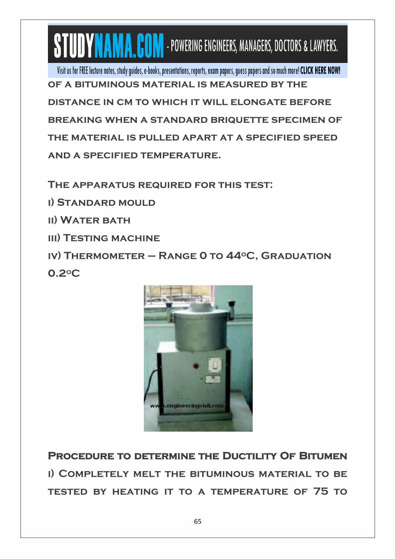
65
of a bituminous material is measured by the
distance in cm to which it will elongate before
breaking when a standard briquette specimen of
the material is pulled apart at a specified speed
and a specified temperature.
The apparatus required for this test:
i) Standard mould
ii) Water bath
iii) Testing machine
iv) Thermometer – Range 0 to 44oC, Graduation
0.2oC
Procedure to determine the Ductility Of Bitumen
i) Completely melt the bituminous material to be
tested by heating it to a temperature of 75 to

66
100oC above the approximate softening point
until it becomes thoroughly fluid. Assemble the
mould on a brass plate and in order to prevent
the material under test from sticking,
thoroughly coat the surface of the plate and the
interior surfaces of the sides of the mould with a
mixture of equal parts of glycerine and dextrin.
While filling, pour the material in a thin stream
back and forth from end to end of the mould until
it is more than level full. Leave it to cool at room
temperature for 30 to 40 minutes and then place
it in a water bath maintained at the specified
temperature for 30 minutes, after which cut off
the excess bitumen by means of a hot, straight-
edged putty knife or spatula, so that the mould is
just level full. ii) Place the brass plate and mould
with briquette specimen in the water bath and
keep it at the specified temperature for about 85
to 95 minutes. Remove the briquette from the
plate, detach the side pieces and the briquette
immediately.
iii) Attach the rings at each end of the two clips to
the pins or hooks in the testing machine and pull
the two clips apart horizontally at a uniform

67
speed, as specified, until the briquette ruptures.
Measure the distance in cm through which the
clips have been pulled to produce rupture. While
the test is being done, make sure that the water in
the tank of the testing machine covers the
specimen both above and below by at least 25mm
and the temperature is maintained continuously
within ± 0.5oC of the specified temperature.
REPORTING OF RESULTS
A normal test is one in which the material
between the two clips pulls out to a point or to a
thread and rupture occurs where the cross-
sectional area is minimum. Report the average of
three normal tests as the ductility of the
sample, provided the three determinations be
within ± 0.5 percent of their mean value.
If the values of the three determinations do not
lie within ± 0.5 percent of their mean, but the two
higher values are within ± 0.5 percent of their
mean, then record the mean of the two higher
values as the test result.

68
Determining Penetration of Bitumen
This test is done to determine the penetration of
bitumen as per IS: 1203 – 1978. The principle is
that the penetration of a bituminous material is
the distance in tenths of a mm, that a standard
needle would penetrate vertically, into a sample
of the material under standard conditions of
temperature, load and time. The apparatus
needed to determine the penetration of bitumen is
i) Penetrometer
ii) Water bath
iii) Bath thermometer – Range 0 to 44oC,
Graduation 0.2oC

69
SAMPLE
Bitumen should be just sufficient to fill the
container to a depth of at least 15mm in excess of
the expected penetration.
Procedure to determine the penetration of
bitumen
i) Soften the bitumen above the softening point
(between 75 and 100oC). Stir it thoroughly to
remove air bubbles and water.
ii) Pour it into a container to a depth of at least
15mm in excess of the expected penetration.
iii) Cool it at an atmospheric temperature of 15 to
30oC for 11/2 hours. Then place it in a transfer
dish in the water bath at 25.0 + 0.1oC for 11/2 hrs.
iv) Keep the container on the stand of the
penetration apparatus.
v) Adjust the needle to make contact with the
surface of the sample.
vi) Adjust the dial reading to zero.
vii) With the help of the timer, release the needle
for exactly 5 seconds.

70
viii) Record the dial reading.
ix) Repeat the above procedure thrice.
REPORTING OF RESULTS
The value of penetration reported should be the
mean of not less than three determinations
expressed in tenths of a mm.

71
MACHINERY USED IN
CONSTRUCTION
LIST OF PLANT & MACHINERY
DEVELOPED AT SITE:
WMM Mixing plant
Tailor
Stone Crusher unit 100TPH

72
Tipper (6/8)
GSB Crusher unit 100 TPH
Tipper (14cum)
Weight Bridge
Tractor
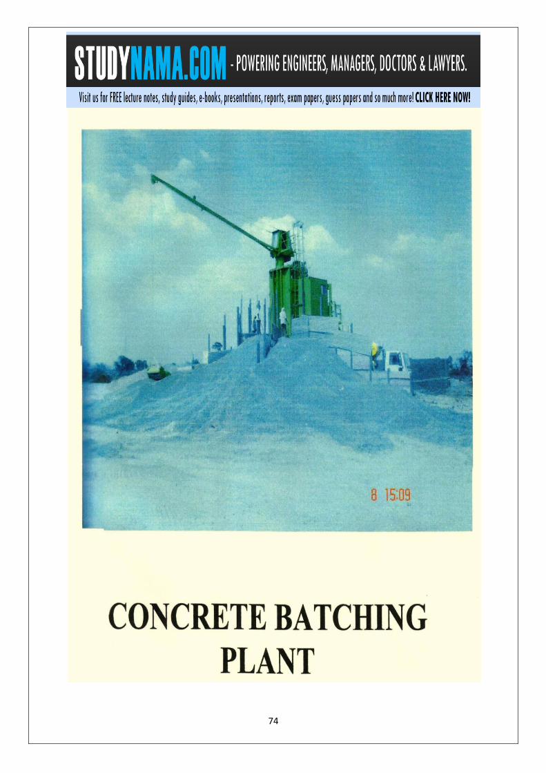
Concrete Batching Plant
Plate Compactor
Transit Mixer
Concrete Mixer
Motor Grader
Generator set 250KVA
Front end loader
Generator set 180KVA
Generator set 125KVA
Generator set 100KVA
Generator set 22KVA
Generator set 17.5KVA
Generator set 5KVA
Excavator
J.C.B

73
Soil Compactor
Sensor Pavers
WMM Pavers
Vibratory Tandem Roller
Static Roller
Hydra
Air Compressor
Needle Vibrator
Water Pump
Bitumen Spryer
Welding set with Generator 8KVA
Mechanical Boomer
Vehicles
Water Tanks


79
SUGGESTION AND
CONCLUSION
1. Civil engineer should perform the work at
their level best so that it will give better
result and improve the production of the
company.
2. Infrastructure of Civil Contractor Cell
should be more developed for giving the
contract to the best contractor.
3. Welfare facilities should be increase in
for civil engineers of Construction
Company.
4. For the safety of civil engineers at the
construction, company should give the
best equipments of safety to the civil
engineers.
80
5. The hostel facility and amenities should
be improved so that the civil engineers
could work with more efficiency.
6. The civil engineers are advised to do their
work in slot as they do it bulk which
create adverse problems for example the
road was dug during the rainy season in
one flow which resulted in heavy loss of
material, money and machinery of the
company. The work should have been done
in small phases and according to the
circumstances. The clipping can be seen
on the next page as to how destruction
was made during the time when I was
undergoing my training.


82
1. I.S. specification book on
highway.
2. Highway material testing
book by
3. S.K. Khanna, C.E.G Justo.
4. Organization’s Laboratory.
5. Organization’s Engineers.

Related Documents