1 23 Arabian Journal for Science and Engineering ISSN 1319-8025 Volume 36 Number 2 Arab J Sci Eng (2011) 36:279-286 DOI 10.1007/ s13369-010-0017-5 A Low-Nonlinearity Laser Heterodyne Interferometer with Quadrupled Resolution in the Displacement Measurement

Welcome message from author
This document is posted to help you gain knowledge. Please leave a comment to let me know what you think about it! Share it to your friends and learn new things together.
Transcript

1 23
Arabian Journal for Scienceand Engineering ISSN 1319-8025Volume 36Number 2 Arab J Sci Eng (2011)36:279-286DOI 10.1007/s13369-010-0017-5
A Low-Nonlinearity Laser HeterodyneInterferometer with QuadrupledResolution in the DisplacementMeasurement

1 23
Your article is protected by copyright and
all rights are held exclusively by King Fahd
University of Petroleum and Minerals. This
e-offprint is for personal use only and shall
not be self-archived in electronic repositories.
If you wish to self-archive your work, please
use the accepted author’s version for posting
to your own website or your institution’s
repository. You may further deposit the
accepted author’s version on a funder’s
repository at a funder’s request, provided it is
not made publicly available until 12 months
after publication.
Arab J Sci Eng (2011) 36:279–286DOI 10.1007/s13369-010-0017-5
RESEARCH ARTICLE - ELECTRICAL ENGINEERING
Saeed Olyaee · Samaneh Hamedi
A Low-Nonlinearity Laser Heterodyne Interferometerwith Quadrupled Resolution in the DisplacementMeasurement
Received: 14 December 2008 / Accepted: 9 February 2010 / Published online: 15 January 2011© King Fahd University of Petroleum and Minerals 2011
Abstract Quantitative analysis has been applied extensively for modeling and compensation of periodic non-linearities since the invention of heterodyne laser interferometers. In this article, we mathematically analyzeand modele the nonlinearity resulting from non-orthogonality and ellipticity of the polarized laser beams fora modified high-resolution nano-displacement measuring system based on a three-mode laser interferometer.Also, we present a simple method to compensate for the periodic nonlinearity in the modified system basedon a two-mode type nonlinearity reduction method. The results reveal that the factor of nonlinearity reductioncan reach a value of 99.9% for some special cases of deviations resulting from non-ideal polarized light. Inaddition to the nonlinearity compensation, we show that the resolution of the displacement measurement inthe modified system is doubled and quadrupled with respect to the conventional three- and two-mode laserheterodyne interferometers, respectively.
Keywords Nano-displacement · Heterodyne · Interferometer · Nonlinearity · Quadrupled resolution
1 Introduction
Over the past decades, the development of laser heterodyne interferometers has led to a resurgence in nano-metrology systems. Technological development of semiconductor devices and circuits has improved resolutionand nano-metrology systems have achieved a high degree of accuracy. Laser heterodyne interferometers have
S. Olyaee (B)Nano-Photonics and Optoelectronics Research Laboratory, Shahid Rajaee Teacher Training University (SRTTU),Lavizan, 16788 Tehran, IranE-mail: [email protected]
S. HamediDepartment of Electrical and Computer Engineering, Shahid Rajaee Teacher Training University (SRTTU),Lavizan, 16788 Tehran, Iran
123
Author's personal copy
280 Arab J Sci Eng (2011) 36:279–286
been widely used in displacement measuring systems with sub-nanometer resolution; they can be found,e.g., in the step and repeat photolithography and masking processes used to generate high density integratedcircuits [1,2].
The displacement accuracy of laser heterodyne interferometers largely influenced fby setup configuration,instrumentation section and environmental effects. It has been shown that the principal limitations of laser inter-ferometers are in photonic noise and residual periodic deviations which are inherent in the periodic signalsof laser interferometers [3]. However, the periodic nonlinearities in phase-displacement response arising frompolarization mixing limit the effective resolution of a laser heterodyne interferometer [4]. Non-orthogonalityand ellipticity of the laser polarization states can cause measurement nonlinearities to arise. Nonlinearity inheterodyne interferometers was first predicted by Quenelle [5] and then reported experimentally by Sutton [6].The nonlinearity of displacement measurement in two-mode laser interferometers has been extensively stud-ied [7–11]. Several techniques have been used to reduce nonlinearity, but most of them do not increase theresolution in spite of using a complicated optical setup.
Guo et al. [12] have presented an optical heterodyne interferometer which enabled significant nonlinearitycompensation and increased system measurement resolution twofold without requiring the doubling of opticalpath length. They used a two-frequency optical source and, based on theoretical analysis, they have shown thatthe system nonlinearity caused by the non-orthogonality and ellipticity of two-frequency input lights can beeasily compensated for.
By using three-mode laser interferometers, resolution can be increased over that of two-mode laser interfer-ometers [13–17]. In this study, we present a low-nonlinearity three-mode laser interferometer with quadrupledresolution in the nanometric displacement measurements. The optical head of the system presented here issimilar to the optical heterodyne interferometer reported by Guo et al. [12], but we use a three-mode laser asa stabilized light source to increase the resolution. Furthermore, the design includes a totally different signalconditioner to extract the secondary beat frequency. In this system, we show that the resolution is doubledwith respect to conventional three-mode laser interferometers and is quadrupled with respect to conventionaltwo-mode laser interferometers. The electrical fields of measurement signals are also calculated based on theJones matrices. The periodic nonlinearity is then analyzed and compared with conventional systems.
The remainder of the article is organized as follows. In the next section we investigate the structure of newoptical system using a three-mode laser. The nonlinearity of the system is analyzed and modeled in Sect. 3.Also the compensation method to reduce the periodic nonlinearity is presented based on the proposed systemby Guo et al. for the two-mode laser interferometer. In Sect. 4, simulation results of the modified three-modelaser interferometer are illustrated and compared with conventional two- and three-mode laser heterodyneinterferometers. Finally, in Sect. 5 the main conclusions are drawn.
2 Structure of Optical Head and Signal Conditioner
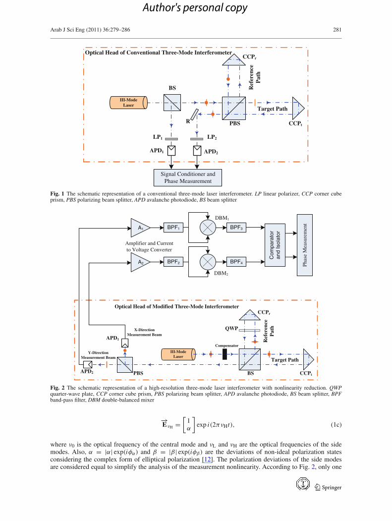
The optical head of the three-mode laser heterodyne interferometer consists of the base arm and measurementarm including, the target and reference paths. Figure 1 shows the schematic diagram of the optical head of aconventional three-mode laser interferometer [13–17]. The output laser beam is first split off by a non-polar-izing beam splitter (BS). The modes of the reflected beams are interfered on the linear polarizer (LP1) toproduce the base signal. The rest are led to the polarizing beam splitter (PBS) and split off according to theirpolarization directions. The reflected beams from two corner cube prisms (CCPs) are interfered to generatethe measurement signal.
In the modified system, the base arm is omitted, as shown in Fig. 2. In addition, a quarter-wave plate(QWP) is inserted into the reference path and linear polarizers are eliminated, because of like polarizationdirections for each beam incident on the avalanche photodiodes (APDs). Figure 3 shows the block diagramof a non-compensated three-mode laser interferometer with quadrupled resolution. The laser beam emergesfrom a stabilized He–Ne laser [14,18,19] at 632.8 nm wavelength. It passes through the non-polarizing beamsplitter, then is led to the target and reference corner cube prisms. The electrical fields of the three non-idealmodes emerging from the laser are respectively given by:
−→EνL =
[1α
]exp i(2πνLt), (1a)
−→Eν0 =
[β1
]exp i(2πν0t), (1b)
123
Author's personal copy
Arab J Sci Eng (2011) 36:279–286 281
PBS
BS
CCPr
CCPt
III-ModeLaser
R
APD1 APD2
Target Path
Ref
eren
ceP
ath
LP1
Signal Conditioner andPhase Measurement
Optical Head of Conventional Three-Mode Interferometer
LP2
Fig. 1 The schematic representation of a conventional three-mode laser interferometer. LP linear polarizer, CCP corner cubeprism, PBS polarizing beam splitter, APD avalanche photodiode, BS beam splitter
BSPBS
CCPr
CCPt
QWP
Compensator
III-ModeLaser
APD1
APD2
Phas
eM
easu
rem
ent
Target Path
Re f
eren
c eP
ath
Y-DirectionMeasurement Beam
X-DirectionMeasurement Beam
A2 BPF2 BPF4
DBM2
Amplifier and Currentto Voltage Converter
A1 BPF1 BPF3
DBM1
Com
par a
tor
and
Isol
ator
Optical Head of Modified Three-Mode Interferometer
Fig. 2 The schematic representation of a high-resolution three-mode laser interferometer with nonlinearity reduction. QWPquarter-wave plate, CCP corner cube prism, PBS polarizing beam splitter, APD avalanche photodiode, BS beam splitter, BPFband-pass filter, DBM double-balanced mixer
−→EνH =
[1α
]exp i(2πνHt), (1c)
where ν0 is the optical frequency of the central mode and νL and νH are the optical frequencies of the sidemodes. Also, α = |α| exp(iφα) and β = |β| exp(iφβ) are the deviations of non-ideal polarization statesconsidering the complex form of elliptical polarization [12]. The polarization deviations of the side modesare considered equal to simplify the analysis of the measurement nonlinearity. According to Fig. 2, only one
123
Author's personal copy
282 Arab J Sci Eng (2011) 36:279–286
Non-Polarizing Beam Splitter
Polarizing Beam Splitter
CC
Pt
CCPr
APD1 APD2
⊥
Laser Beam
QWP
Reference Optical Frequencies
0∠Lν
||||
0∠Hν00∠ν
⊥
Shifted Optical Frequencies
φν Δ∠L
||
φν Δ∠Hφν Δ∠0
⊥
⊥
0∠Lν
||
0∠Hν00∠ν
⊥
00 0 ∠Δ∠∠ HL νφνν φννφν Δ∠∠Δ∠ HL 00
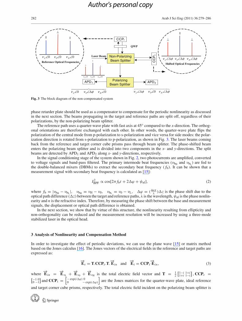
Fig. 3 The block diagram of the non-compensated system
phase retarder plate should be used as a compensator to compensate for the periodic nonlinearity as discussedin the next section. The beams propagating in the target and reference paths are split off, regardless of theirpolarizations, by the non-polarizing beam splitter.
The reference path uses a quarter-wave plate with fast axis at 45◦ compared to the x-direction. The orthog-onal orientations are therefore exchanged with each other. In other words, the quarter-wave plate flips thepolarization of the central mode from p-polarization to s-polarization and vice versa for side modes: the polar-ization direction is rotated from s-polarization to p-polarization, as shown in Fig. 3. The laser beams comingback from the reference and target corner cube prisms pass through beam splitter. The phase-shifted beamenters the polarizing beam splitter and is divided into two components in the x- and y-directions. The splitbeams are detected by APD1 and APD2 along x- and y-directions, respectively.
In the signal conditioning stage of the system shown in Fig. 2, two photocurrents are amplified, convertedto voltage signals and band-pass filtered. The primary intermode beat frequencies (νbH and νbL ) are fed tothe double-balanced mixers (DBMs) to extract the secondary beat frequency ( fb). It can be shown that ameasurement signal with secondary beat frequency is calculated as [15]:
I 2BPF ∝ cos[2π fbt + 2�ϕ + ψnl], (2)
where fb = |νbH − νbL |, νbH = νH − ν0, νbL = ν0 − νL, �ϕ = ( 4nπλ)�z is the phase shift due to the
optical path difference (�z) between the target and reference paths, λ is the wavelength,ψnl is the phase nonlin-earity and n is the refractive index. Therefore, by measuring the phase shift between the base and measurementsignals, the displacement or optical path difference is obtained.
In the next section, we show that by virtue of this structure, the nonlinearity resulting from ellipticity andnon-orthogonality can be reduced and the measurement resolution will be increased by using a three-modestabilized laser in the optical head.
3 Analysis of Nonlinearity and Compensation Method
In order to investigate the effect of periodic deviations, we can use the plane wave [15] or matrix methodbased on the Jones calculus [16]. The Jones vectors of the electrical fields in the reference and target paths areexpressed as:
−→E r = T.CCPr.T.
−→E in and
−→E t = CCPt
−→·E in, (3)
where−→E in = −→
EνL + −→Eν0 + −→
EνH is the total electric field vector and T = 12
[1−i 1+i1+i 1−i
],CCPr =[−1 0
0 −1
]and CCPt =
[− exp(i�ϕ) 00 − exp(i�ϕ)
]are the Jones matrices for the quarter-wave plate, ideal reference
and target corner cube prisms, respectively. The total electric field incident on the polarizing beam splitter is
123
Author's personal copy
Arab J Sci Eng (2011) 36:279–286 283
then concluded as:
−→E PBS = −→
E t + −→E r =
[− exp(i�φ) −1−1 − exp(i�φ)
]−→E in . (4)
After passing through the PBS, APD1 and APD2 measure beams along x- and y-polarization directions, respec-tively:
−→EAPD1 = PBSX .
−→EPBS and
−→EAPD2 = PBSY .
−→EPBS, (5)
where PBSX = [1 00 0
]and PBSY = [
0 00 1
]are the ideal Jones matrices of polarizing beam splitter in x- and
y-directions, respectively. Consequently, the electric fields vectors of three modes VL , V0andVH received byAPD1 are respectively expressed as:
−→E rL + −→
E tL = 1
2exp[i(2πνLt +�ϕ)](1 + |α| exp[i(ϕα −�ϕ)]), (6a)
−→E r0 + −→
E t0 = 1
2exp(i2πν0t)(1 + |β| exp[i(ϕβ +�ϕ)]), (6b)
−→E rH + −→
E tH = 1
2exp[i(2πνHt +�ϕ)](1 + |α| exp[i(ϕα −�ϕ)]). (6c)
where subscripts t and r denote the electrical fields in the target and reference paths, respectively. Similarlyfor APD2(as shown in Fig. 3) we can write:
−→E rL + −→
E tL = 1
2exp(i2πνLt)(1 + |α| exp[i(ϕα +�ϕ)]), (7a)
−→E r0 + −→
E t0 = 1
2exp[i(2πν0t +�ϕ)](1 + |β| exp[i(ϕβ −�ϕ)]), (7b)
−→E rH + −→
E tH = 1
2exp(i2πνHt)(1 + |α| exp[i(ϕα +�ϕ)]). (7c)
Therefore, the real part of the electrical fields received by APD1 can be rewritten as:
ErL + EtL = AL cos(2πνLt +�ϕ + ψ1), (8a)
Er0 + Et0 = A0 cos(2πν0t + ψ2), (8b)
ErH + EtH = AH cos(2πνHt +�ϕ + ψ3), (8c)
where
AL = AH = 1
2
√1 + |α|2 + 2|α| cos[ϕα −�ϕ], (9)
A0 = 1
2
√1 + |β|2 + 2 |β| cos[ϕβ +�ϕ]. (10)
In practical cases, the non-orthogonality of the polarized laser beams is much less than unity, |α| << 1and |β| << 1. Therefore, the phase nonlinearities terms can be approximated as:
ψ1 = ψ3 ≈ |α| sin(ϕα −�ϕ), (11)
ψ2 ≈ |β| sin(�ϕ + ϕβ). (12)
According to the square law behavior of APD and by using Eq. 8, the extracted signal from a double-balanced mixer and band-pass filter is given by [15]:
Iom1 = cos(2π fbt + ψ1 − 2ψ2 + ψ3 + 2�ϕ). (13)
Following the same approach for measurement photocurrent of APD2, the output signal is given as:
Iom2 = cos(2π fbt + ψ ′1 − 2ψ ′
2 + ψ ′3 − 2�ϕ), (14)
123
Author's personal copy
284 Arab J Sci Eng (2011) 36:279–286
where
ψ ′1 = ψ ′
3 ≈ |α| sin(�ϕ + ϕα), (15)
ψ ′2 ≈ |β| sin(ϕβ −�ϕ). (16)
Finally, the phase difference between two measured output signals (��) is extracted as:
�� = 4�ϕ + ψnl = (16nπ/λ)�z + ψnl. (17)
The first term is referred to the increased resolution compared to the other systems, and the second term isthe nonlinearity that is described as:
ψnl = (ψ1 − ψ ′
1
) − 2(ψ2 − ψ ′
2
) + (ψ3 − ψ ′
3
) ≈ −4 sin�ϕ[|α| cosϕα + |β| cosϕβ
]. (18)
If the input polarized beams are orthogonal, the nonlinearity described by Eq. 18 will be zero. However, inreality, this condition does not occur. The nonlinearity can be reduced by inserting one optical phase compen-sator. The fast axis of the compensator is oriented along the x-direction, and therefore, a relative phase delay φcbetween the x- and y-directions is obtained. Consequently, polarized beams passing through the compensatorare shifted and new nonlinearities are given by:
ψ1 = ψ3 ∼= |α| sin(ϕα + ϕc −�ϕ), (19)
ψ2 ∼= |β| sin(ϕβ − ϕc +�ϕ), (20)
ψ ′1 = ψ ′
3∼= |α| sin(�ϕ + ϕα + ϕc), (21)
ψ ′2
∼= |β| sin(ϕβ − ϕc −�ϕ). (22)
The compensated nonlinearity is then finalized as:
ψcnl = −4 sin�ϕ[|α| cos(ϕα + ϕc)+ |β| cos(ϕβ − ϕc)
], (23)
tan ϕc_opt = |α| cosϕα + |β| cosϕβ|α| sin ϕα − |β| sin ϕβ
. (24)
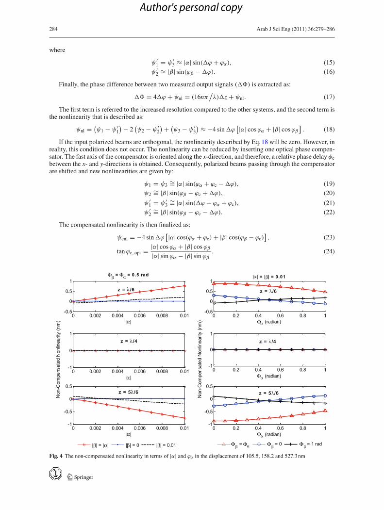
Fig. 4 The non-compensated nonlinearity in terms of |α| and ϕα in the displacement of 105.5, 158.2 and 527.3 nm
123
Author's personal copy
Arab J Sci Eng (2011) 36:279–286 285
The optimized angle of the retarder plate φc_opt depends only on the polarization orientation of the laserbeams. Comparison of two-mode [12] and modified three-mode laser interferometers shows that the optimizedphase shift due to the phase retarder plate is not changed.
4 Simulation Results
To show the effectiveness of the simple compensation method presented here on the measurement nonlinearity,we calculate it for a high-resolution three-mode laser interferometer compared with conventional two-modelaser interferometers. The non-compensated nonlinearities in terms of |α| and φα are shown in Fig. 4 forthe optical path differences of 105.5 nm (λ/6), 158.2 nm (λ/4) and 527.3 nm (5λ/6). If �z = mλ/16, thenonlinearity is equal to zero, where m is an integer.
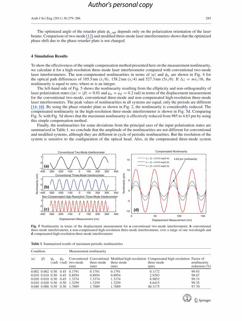
The left-hand side of Fig. 5 shows the nonlinearity resulting from the ellipticity and non-orthogonality oflaser polarization states (|α| = |β| = 0.01 and ϕα = ϕβ = 0.2 rad) in terms of the displacement measurementfor the conventional two-mode, conventional three-mode and non-compensated high-resolution three-modelaser interferometers. The peak values of nonlinearities in all systems are equal; only the periods are different[14–16]. By using the phase retarder plate as shown in Fig. 2, the nonlinearity is considerably reduced. Thecompensated nonlinearity in the high-resolution three-mode interferometer is shown in Fig. 5d. ComparingFig. 5c with Fig. 5d shows that the maximum nonlinearity is effectively reduced from 985 to 4.63 pm by usingthis simple compensation method.
Finally, the nonlinearities for some deviations from the principal axes of the input polarization states aresummarized in Table 1. we conclude that the amplitude of the nonlinearities are not different for conventionaland modified systems, although they are different in cycle of periodic nonlinearities. But the resolution of thesystem is sensitive to the configuration of the optical head. Also, in the compensated three-mode system
-400 -300 -200 -100 0 100 200 300 400-1
0
1
Displacement Measurement (nm)
Non-Compensated High-Resolution Three-Mode Interferometer-400 -300 -200 -100 0 100 200 300 400-1
0
1
Non
linea
rity
(nm
)
Conventional Three-Mode Interferometer-400 -300 -200 -100 0 100 200 300 400-1
0
1
Conventional Two-Mode Interferometer
(a)
(b)
(c)
0 50 100 150
-10
-5
0
5
10
15
Displacement Measurement (nm)
Non
linea
rity
(pm
)
Compensated Nonlinearity
α = β = 0.010 exp(0.5i)
α = β = 0.010 exp(0.2i)
α = β = 0.015 exp(0.2i)
(d)
4.63 pm nonlinearity
Fig. 5 Nonlinearity in terms of the displacement measurement for a conventional two-mode interferometer, b conventionalthree-mode interferometer, c non-compensated high-resolution three-mode interferometer, over a range of one wavelength andd compensated high-resolution three-mode interferometer
Table 1 Summarized results of maximum periodic nonlinearities
Condition Measurement nonlinearity
|α| |β| φα φβ Conventional Conventional Modified high-resolution Compensated high-resolution Factor of( rad) ( rad) two-mode three-mode three-mode three-mode nonlinearity
(nm) (nm) (nm) (pm) reduction (%)
0.002 0.002 0.50 0.45 0.1791 0.1791 0.1791 0.1172 99.930.010 0.010 0.50 0.45 0.8954 0.8954 0.8954 2.9293 99.670.020 0.010 0.50 0.45 1.3374 1.3374 1.3374 8.9852 99.330.010 0.020 0.50 0.50 1.3259 1.3259 1.3259 8.6415 99.350.040 0.000 0.50 0.50 1.7689 1.7689 1.7689 40.3175 97.70
123
Author's personal copy
286 Arab J Sci Eng (2011) 36:279–286
the amplitude of nonlinearity is effectively reduced. It can be seen that the factor of nonlinearity reduction forthe present system can reach a value of 99.9% for some special cases, ignoring environmental errors.
5 Conclusions
The nonlinearity resulting from ellipticity and non-orthogonality of the laser polarization beams in a simplehigh-resolution three-mode laser interferometer has been analyzed. The results were compared with conven-tional two- and three-mode laser interferometers. In the non-compensated case, the peak-to-peak nonlinearitywas the same as that of conventional types except at the period of nonlinearity. There, in addition to thenonlinearity reduction, we have shown that the resolution of the displacement measurement is increased by afactor of four compared to that of conventional two-mode laser interferometers.
Acknowledgments The authors would like to thank the anonymous referees for their impressive and helpful comments andsuggestions which considerably improved the contents and the presentation of the manuscript.
References
1. Schattenburg ML, Smith HI (2001) The critical role of metrology in nanotechnology. Proc SPIE 4608:116–1242. Demarest FC (1998) High-resolution, high-speed, low data age uncertainty, heterodyne displacement measuring interfer-
ometer electronics. Meas Sci Technol 9:1024–10303. Cosijns SJAG, Haitjema H, Schellekens PHJ (2002) Modeling and verifying non-linearities in heterodyne displacement
interferometry. Precision Eng 26:448–4554. Hou W, Zhang Y, Hu H (2009) A simple technique for eliminating the nonlinearity of a heterodyne interferometer. Meas
Sci Technol 20:1–65. Quenelle RC (1983) Nonlinearity in interferometric measurements. Hewlett-Parkard J 34(4):106. Sutton CM (1987) Nonlinearity in the length measurement using heterodyne laser Michelson interferometry. J Phys E Sci
Instrum 20:1290–12927. Hou W, Wilkening G (1992) Investigation and compensation of the nonlinearity of heterodyne interferometers. Precision
Eng 14:91–988. Wu C, Su C (1996) Nonlinearity in measurements of length by optical interferometry. Meas Sci Technol 7:62–689. Olyaee S, Ebrahimpour R, Hamedi S (2010) Modeling and compensation of periodic nonlinearity in two-mode laser het-
erodyne interferometer using stacked generalization method. IETE J Res 56(2):102–11010. Freitas JM (1997) Analysis of laser source birefringence and dichroism on nonlinearity in heterodyne interferometry. Meas
Sci Technol 8:1356–135911. Wu C, Deslattes R (1998) Analytical modeling of the periodic nonlinearity in heterodyne interferometry. Appl Opt 37:
6696–670012. Guo J, Zhang Y, Shen S (2000) Compensation of nonlinearity in a new optical heterodyne interferometer with doubled
measurement resolution. Opt Commun 184:49–5513. Yokoyama T, Araki T, Yokoyama S, Suzuki N (2001) A subnanometre heterodyne interferometric system with improved
phase sensitivity using a three-longitudinal-mode He–Ne laser. Meas Sci Technol 12:157–16214. Olyaee S, Nejad SM (2007) Design and simulation of velocity and displacement measurement system with subnanometer
uncertainty based on a new stabilized laser Doppler-interferometer. Arab J Sci Eng 32(2C):89–9915. Olyaee S, Nejad SM (2007) Nonlinearity and frequency-path modelling of three-longitudinal-mode nanometric displace-
ment measurement system. IET Optoelectron 1(5):211–22016. Olyaee S, Yoon TH, Hamedi S (2009) Jones matrix analysis of frequency mixing error in three-longitudinal-mode laser
heterodyne interferometer. IET Optoelectron 3(5):215–22417. Yokoyama S, Yokoyama T, Araki T (2005) High-speed subnanometre interferometry using an improved three-mode het-
erodyne interferometer. Meas Sci Technol 16:1841–184718. Suh HS, Yoon TH, Chung MS, Choi OS (1993) Frequency and power stabilization of a three longitudinal mode He-Ne laser
using secondary beat frequency. Appl Phys Lett 63:2027–202919. Yeom JY, Yoon TH (2005) Three-longitudinal-mode He–Ne laser frequency stabilized at 633 nm by thermal phase locking
of the secondary beat frequency. Appl Opt 44(2):266–270
123
Author's personal copy
Related Documents


