Citation: Andrianov, A.; Tomita, E.K.; Veras, C.A.G.; Telles, B. A Low-Cost Filament Winding Technology for University Laboratories and Startups. Polymers 2022, 14, 1066. https:// doi.org/10.3390/polym14051066 Academic Editor: Dagmar R. D’hooge Received: 27 January 2022 Accepted: 3 March 2022 Published: 7 March 2022 Publisher’s Note: MDPI stays neutral with regard to jurisdictional claims in published maps and institutional affil- iations. Copyright: © 2022 by the authors. Licensee MDPI, Basel, Switzerland. This article is an open access article distributed under the terms and conditions of the Creative Commons Attribution (CC BY) license (https:// creativecommons.org/licenses/by/ 4.0/). polymers Article A Low-Cost Filament Winding Technology for University Laboratories and Startups Artem Andrianov 1, * , Erika Kamada Tomita 1 , Carlos Alberto Gurgel Veras 2 and Bruno Telles 1 1 Aerospace Engineering Course, University of Brasilia, Área Especial de Indústria Projeção A, Setor Leste (Gama), Brasília 72444-240, Brazil; [email protected] (E.K.T.); [email protected] (B.T.) 2 Mechanical Engineering Department, Campus Universitário Darcy Ribeiro, University of Brasilia, Brasília 70970-900, Brazil; [email protected] * Correspondence: [email protected]; Tel.: +55-61-982344735 Abstract: This paper systematically explains the methodology and results of empirical work on the development of a low-cost filament winding technology for manufacturing axisymmetric polymer composite structures with a high length-to-diameter ratio, such as tubes, motor casings, and pressure vessels. The principal objective was to examine the experiences and most optimal practices in the development of computer-controlled equipment and auxiliary tooling for the wet filament-winding process. To preclude expensive commercial software for the automated control of a winding machine, analytical equations were derived for the winding trajectory of a four-axis filament-winding machine. The feasibility of the proposed equations was successfully validated by laying the fiber along the geodesic path marked on the surface of a cylindrical mandrel with hemispherical ends. Moreover, the carbon/epoxy cylindrical casings with hemispherical ends and port openings of the same diameter were wound to determine the thickness distribution in the hemispherical dome. The fiber volume ratio in the wound composite parts was evaluated using an optical technique. Keywords: filament winding; winding trajectory; composite casing; polymer composite 1. Introduction Filament winding technology has been deployed extensively in the aerospace industry since the early 1940s [1] and has persistently garnered interest from the scientific com- munity. Data from Google Scholar, published in an insightful review on the automated manufacturing and processing of fiber-reinforced polymer composites, revealed the pres- ence of a markedly high number of papers concerned with filament winding even in recent times [2]. However, the acquisition of composite structures with a unique shape of revolu- tion and dimensions by university laboratories or startups requires sizeable investments. Under these conditions, small companies typically seek alternative solutions. University teams, however, can potentially benefit from sponsorship by equipment manufacturers, as demonstrated in the case of the production of filament-wound rocket fuselages [3]. Another tenable solution is the development of in-house low-cost equipment for filament winding [4]. A multitude of reports have highlighted the practicability of in-house laboratory equip- ment for assessing new filament winding techniques and for the experimental fabrication of advanced composite materials. Reference [5] presents a five-axis filament winding machine (FWM), including a numerical control unit and liner. It is suggested in [6] to increase the fiber volume ratio and decrease the void volume ratio of the composite casing. An environmentally friendly FWM, without any discernible loss of quality was devised by the separation of the resin components with their controllable feeding initially to a conventional static-mixer and subsequently to a custom-designed resin impregnation unit [7,8]. In the study reported in [9], the development of a controller using the B-spline interpolation tech- nique entailed the construction of a three-axis FWM. A succinct description of the filament Polymers 2022, 14, 1066. https://doi.org/10.3390/polym14051066 https://www.mdpi.com/journal/polymers

Welcome message from author
This document is posted to help you gain knowledge. Please leave a comment to let me know what you think about it! Share it to your friends and learn new things together.
Transcript
�����������������
Citation: Andrianov, A.; Tomita, E.K.;
Veras, C.A.G.; Telles, B. A Low-Cost
Filament Winding Technology for
University Laboratories and Startups.
Polymers 2022, 14, 1066. https://
doi.org/10.3390/polym14051066
Academic Editor: Dagmar
R. D’hooge
Received: 27 January 2022
Accepted: 3 March 2022
Published: 7 March 2022
Publisher’s Note: MDPI stays neutral
with regard to jurisdictional claims in
published maps and institutional affil-
iations.
Copyright: © 2022 by the authors.
Licensee MDPI, Basel, Switzerland.
This article is an open access article
distributed under the terms and
conditions of the Creative Commons
Attribution (CC BY) license (https://
creativecommons.org/licenses/by/
4.0/).
polymers
Article
A Low-Cost Filament Winding Technology for UniversityLaboratories and StartupsArtem Andrianov 1,* , Erika Kamada Tomita 1, Carlos Alberto Gurgel Veras 2 and Bruno Telles 1
1 Aerospace Engineering Course, University of Brasilia, Área Especial de Indústria Projeção A,Setor Leste (Gama), Brasília 72444-240, Brazil; [email protected] (E.K.T.); [email protected] (B.T.)
2 Mechanical Engineering Department, Campus Universitário Darcy Ribeiro, University of Brasilia,Brasília 70970-900, Brazil; [email protected]
* Correspondence: [email protected]; Tel.: +55-61-982344735
Abstract: This paper systematically explains the methodology and results of empirical work on thedevelopment of a low-cost filament winding technology for manufacturing axisymmetric polymercomposite structures with a high length-to-diameter ratio, such as tubes, motor casings, and pressurevessels. The principal objective was to examine the experiences and most optimal practices in thedevelopment of computer-controlled equipment and auxiliary tooling for the wet filament-windingprocess. To preclude expensive commercial software for the automated control of a winding machine,analytical equations were derived for the winding trajectory of a four-axis filament-winding machine.The feasibility of the proposed equations was successfully validated by laying the fiber along thegeodesic path marked on the surface of a cylindrical mandrel with hemispherical ends. Moreover, thecarbon/epoxy cylindrical casings with hemispherical ends and port openings of the same diameterwere wound to determine the thickness distribution in the hemispherical dome. The fiber volumeratio in the wound composite parts was evaluated using an optical technique.
Keywords: filament winding; winding trajectory; composite casing; polymer composite
1. Introduction
Filament winding technology has been deployed extensively in the aerospace industrysince the early 1940s [1] and has persistently garnered interest from the scientific com-munity. Data from Google Scholar, published in an insightful review on the automatedmanufacturing and processing of fiber-reinforced polymer composites, revealed the pres-ence of a markedly high number of papers concerned with filament winding even in recenttimes [2]. However, the acquisition of composite structures with a unique shape of revolu-tion and dimensions by university laboratories or startups requires sizeable investments.Under these conditions, small companies typically seek alternative solutions. Universityteams, however, can potentially benefit from sponsorship by equipment manufacturers,as demonstrated in the case of the production of filament-wound rocket fuselages [3].Another tenable solution is the development of in-house low-cost equipment for filamentwinding [4].
A multitude of reports have highlighted the practicability of in-house laboratory equip-ment for assessing new filament winding techniques and for the experimental fabrication ofadvanced composite materials. Reference [5] presents a five-axis filament winding machine(FWM), including a numerical control unit and liner. It is suggested in [6] to increasethe fiber volume ratio and decrease the void volume ratio of the composite casing. Anenvironmentally friendly FWM, without any discernible loss of quality was devised by theseparation of the resin components with their controllable feeding initially to a conventionalstatic-mixer and subsequently to a custom-designed resin impregnation unit [7,8]. In thestudy reported in [9], the development of a controller using the B-spline interpolation tech-nique entailed the construction of a three-axis FWM. A succinct description of the filament
Polymers 2022, 14, 1066. https://doi.org/10.3390/polym14051066 https://www.mdpi.com/journal/polymers
Polymers 2022, 14, 1066 2 of 27
winding hardware that features precision guidance of the carbon nanotube-based materialis given in [10]. A “spiral-winder” was developed for the manufacturing cylindrical lami-nated veneer lumber in [11]. The majority of the said research had a narrow purview withtheir focus on specific scientific problems and engineering solutions related to filamentwinding technology, and only a few details were presented regarding the cost-effectivedesign of the filament winder, its control system, and winding technique.
The volume ratio and decrease in the void volume ratio of the composite casing wererecorded. An environmentally friendly FWM, without any discernible loss of quality wasdevised by the separation of the resin components with their controllable feeding initiallyto a conventional static-mixer and subsequently to a custom-designed resin impregnationunit [7,8]. In the study reported in [9], the development of a controller using B-spline inter-polation technique entailed the construction of a three-axis FWM. A succinct description ofthe filament winding hardware that features precision guidance of the carbon nanotube-based material is given in [10]. A “spiral-winder” was developed for the manufacturingcylindrical laminated veneer lumber in [11]. The majority of the said research works had anarrow purview with their focus on specific scientific problems and engineering solutionsrelated to filament winding technology, and only a few details were presented regardingthe cost-effective design of the filament winder, its control system, and winding technique.
The methodology and results of one of the first attempts to design a low-cost computer-operated wet filament winding system for manufacturing cylindrical and conical partsor a combination of components are delineated in [12]. The associated system is accom-panied by a software written in the AUTOLISP parametric programming language forthe visualization of the winding patterns. Another innovative lathe-type machine basedon a wet winding method is presented in [13]. The cost of the system is low becauseof the implementation of a rigid automation: the control system is not controlled by acomputer, but is rather based on relays, limit switches, a timer, and a counter. Similarlow-cost design solutions have been presented, which are based on a speed control of twoDC [14] or AC motors [15]. An ingenious small-scale FWM has also been developed foreducational purposes [16]. This machine generates helical winding patterns with anglesranging from 40 degrees to 80 degrees. The mandrel is driven by a cheap AC motor witha relatively constant speed. The translational motion of the carriage with delivery eye isprovided by a stepper motor, which is more sophisticated in terms of control. All of thementioned systems have only two controllable axes that apply known limitations on avariety of wound parts.
An example of modernization of a two-axis winder by adding two more controllableaxes is systematically detailed in [17]. In fact, one axis is adjusted manually (the distancebetween delivery eye and mandrill) and the other axes are driven by three DC motorswith the same number of controllers. An efficacious low-cost solution is presented in [18],wherein a three-axis filament winder is equipped with one AC motor for the mandrelrotation and two AC servo-motors for the translation of the carriage. Servo-motors arecontrolled by the LabView software. A three-axis portable FWM was developed with anextensive use of the standard accessories for fabrication of hobby and laboratory machines,such as OpenBuilds V-Slot aluminum profile and other parts (bearings, fixtures, pulleys,belts, etc.) [19]. All the three axes of the winder are driven by stepper motors and controlledby the microcontroller Arduino Uno and drive the expansion board computer numericcontrol (CNC) Shield. Universal G-Code Sender software is used to send commands fromthe computer to the winder in [20]. More recently, winders were equipped with mobilesoftware for wireless control [21]. The winding performance was assessed as satisfactory inaccordance with the criteria of the angle deviations and accuracy of the distance betweentwo adjacent helical roving positions in [22]. In addition, tubular structures have beenmanufactured with the use of commercial software for generation of winding trajectory [23].Notwithstanding the low-cost design philosophy deemed critical in the aforementionedprojects, the validation of the final product has been demonstrated for the structuralcomponents with a non-sophisticated shape, such as tubes.

Polymers 2022, 14, 1066 3 of 27
A methodical description of a three-axis filament winder with an original technicalsolution for the third degree of freedom (DOF) is given in the references [24,25]. Fibers areconsolidated by a twisting of the tow to form a bar of a circular cross-section. The twistingcan be performed by a rotation of the delivery carriage. Nevertheless, the developed equip-ment only allows for the manufacturing of wrapped tow reinforced trusses. A meticulousdescription of small-scale equipment with four DOF that combines the filament windingwith automated fiber placement is provided in reference [26]. A noteworthy advantage ofthe contemporary technology is the likelihood of manufacturing components with concavesurfaces. However, the validation was fulfilled only with numerical simulations and notby manufacturing the test specimen, the former being less complex and arduous thanthe latter.
At present, there exist several commercial programs for generating the filament wind-ing trajectories that use the mandrel’s shape as the initial data [27]. As stated in [28], amore intricate approach for path generation is currently under investigation to enhance thequality of the final product. The approach considers the alteration in the mandrel’s shapedue to an uneven thickness distribution of the ply from previous winding. Acquisition ofthe commercial software for path generation increases the final cost of the technology, andthe latter approach requires the application of expensive equipment.
Another way to make the technology more cost-effective is the development of ana-lytical solutions to determine the winding trajectories performed by components of theFWM [29]. Depending on the shape of the mandrel, the fibers are laid along geodesic ornon-geodesic trajectories. In accordance with reference [30], which contains analytical solu-tions for the winding paths of the parameterized shells of revolution, geodesic trajectoriesprovide the most stable and economical technique for filament-wound structures.
An efficacious, viable solution for the smooth winding motion is delineated in [29].However, it is applicable only for two-axis FWMs. An analytical solution for four- andfive-axis machines is described in the form of the coordinates for the feed-eye trajectoryand the mandrel rotation [5,31]. Nevertheless, the solution in reference [5] only providessatisfactory results for the spherical dome when the distance from the delivery eye to thesurface of the mandrel is zero. A generic kinematic model of the machine movementsto create a particular filament-wound product, on a particular machine configuration, isdiscussed in reference [32]. The mathematical approach adopted for the derivation of theexecutive expressions in [31,32] demands tremendous effort or skill from an FWM operator.
The primary objective of this work was to design low-cost computer-controlled equip-ment for the filament winding of small-size axisymmetric aerospace structures, such astubes, casings, and pressure vessels. The secondary objective of the work was to obtainsimple and comprehensive analytical equations for the delivery eye trajectory by referringonly to analytic geometry. The derived equations were used for the winding of a cylindricalcasing with hemispherical domes, whose polar openings are of the same diameter.
The validation of the suggested low-cost winding technology was conducted bymanufacturing small-scale composite casings to evaluate the thickness and fiber volumeratio of helical plies. The dimensions of the designed casing are close to the size of the testmotor of a hybrid propellant decelerator [33].
2. Materials and Methods2.1. Constituents of the Composite Material
Carbon fiber, being the most difficult fiber to manage [1], has been used in this studyin the filament-winding process to appraise the capability of the proposed system underdemanding situations. Continuous carbon fiber tows based on polyacrylonitrile Teijin Car-bon HTS45 E23 12K (Table 1) and epoxy resins of different grades produced by Huntsman(Table 2) were used for manufacturing the casing on the developed winding machine.
Polymers 2022, 14, 1066 4 of 27
Table 1. Properties of the carbon fiber tow 1.
Parameter Minimal Nominal Maximal
ρ f , tex 720 800 880ρ, g/cm3 1.77 1.80 1.83F1 f , MPa 4050 4500 4950E1 f , GPa 228 240 252
1 as affirmed by local supplier Texiglass.
Table 2. Cure schedules for three types of resin-impregnated tows.
Designation Resin Composition Initial Viscosity at25 ◦C 1, mPa·s Cure Schedule
LY1564 AralditeLY1564/XB3473 1000–1200 30 min at 130 ◦C + 12 h at
160 ◦C
LY5052Araldite
LY5052/AradurTM5052
600–700(to 1500 after 56–60 min) 24 h at 25 ◦C + 15 h at 60 ◦C
1 manufacturer’s data.
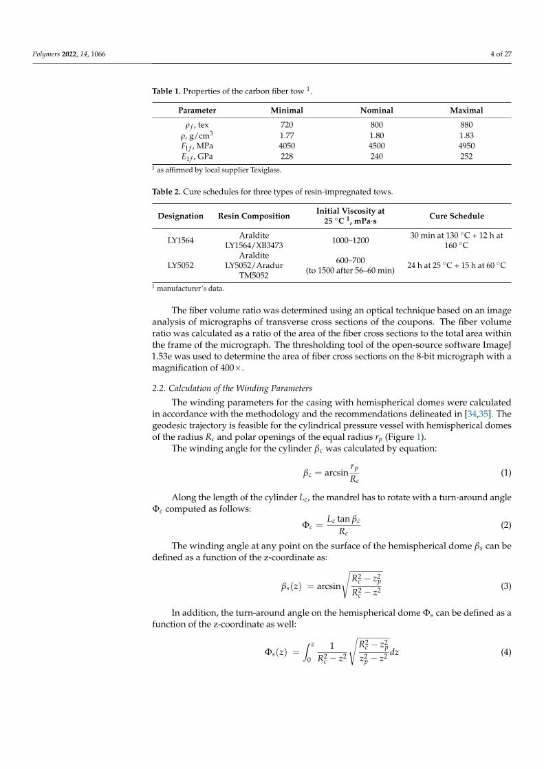
The fiber volume ratio was determined using an optical technique based on an imageanalysis of micrographs of transverse cross sections of the coupons. The fiber volumeratio was calculated as a ratio of the area of the fiber cross sections to the total area withinthe frame of the micrograph. The thresholding tool of the open-source software ImageJ1.53e was used to determine the area of fiber cross sections on the 8-bit micrograph with amagnification of 400×.
2.2. Calculation of the Winding Parameters
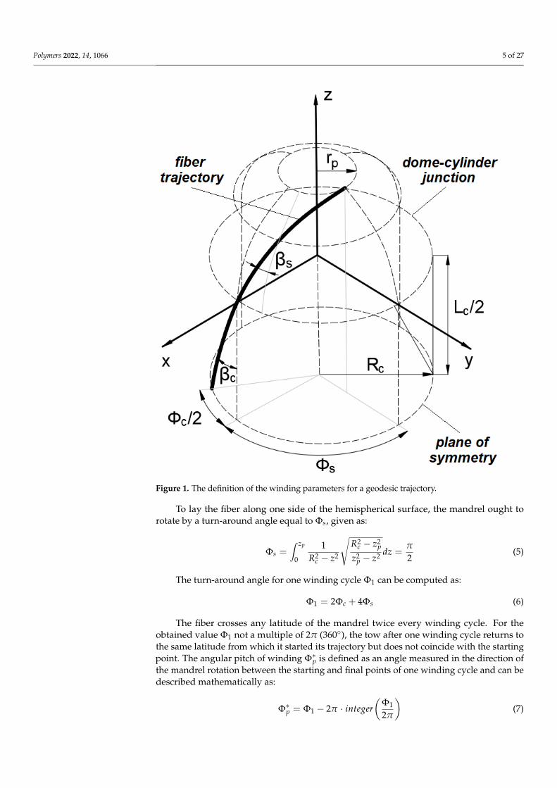
The winding parameters for the casing with hemispherical domes were calculatedin accordance with the methodology and the recommendations delineated in [34,35]. Thegeodesic trajectory is feasible for the cylindrical pressure vessel with hemispherical domesof the radius Rc and polar openings of the equal radius rp (Figure 1).
The winding angle for the cylinder βc was calculated by equation:
βc = arcsinrp
Rc(1)
Along the length of the cylinder Lc, the mandrel has to rotate with a turn-around angleΦc computed as follows:
Φc =Lc tan βc
Rc(2)
The winding angle at any point on the surface of the hemispherical dome βs can bedefined as a function of the z-coordinate as:
βs(z) = arcsin
√R2
c − z2p
R2c − z2 (3)
In addition, the turn-around angle on the hemispherical dome Φs can be defined as afunction of the z-coordinate as well:
Φs(z) =∫ z
0
1R2
c − z2
√R2
c − z2p
z2p − z2 dz (4)
Polymers 2022, 14, 1066 5 of 27Polymers 2022, 14, x FOR PEER REVIEW 5 of 27
Figure 1. The definition of the winding parameters for a geodesic trajectory.
The winding angle for the cylinder 𝛽 was calculated by equation: 𝛽 = arcsin 𝑟𝑅 (1) Along the length of the cylinder Lc, the mandrel has to rotate with a turn-around
angle Φ computed as follows: Φ = 𝐿 tan 𝛽 𝑅 (2)
The winding angle at any point on the surface of the hemispherical dome 𝛽 can be defined as a function of the z-coordinate as:
𝛽 (𝑧) = arcsin 𝑅 − 𝑧𝑅 − 𝑧 (3)
In addition, the turn-around angle on the hemispherical dome Φ can be defined as a function of the z-coordinate as well:
Φ (𝑧) = 1𝑅 − 𝑧 𝑅 − 𝑧𝑧 − 𝑧 𝑑𝑧 (4)
To lay the fiber along one side of the hemispherical surface, the mandrel ought to rotate by a turn-around angle equal to Φ , given as:
Φ = 1𝑅 − 𝑧 𝑅 − 𝑧𝑧 − 𝑧 𝑑𝑧 = 𝜋2 (5)
Figure 1. The definition of the winding parameters for a geodesic trajectory.
To lay the fiber along one side of the hemispherical surface, the mandrel ought torotate by a turn-around angle equal to Φs, given as:
Φs =∫ zp
0
1R2
c − z2
√R2
c − z2p
z2p − z2 dz =
π
2(5)
The turn-around angle for one winding cycle Φ1 can be computed as:
Φ1 = 2Φc + 4Φs (6)
The fiber crosses any latitude of the mandrel twice every winding cycle. For theobtained value Φ1 not a multiple of 2π (360◦), the tow after one winding cycle returns tothe same latitude from which it started its trajectory but does not coincide with the startingpoint. The angular pitch of winding Φ∗p is defined as an angle measured in the direction ofthe mandrel rotation between the starting and final points of one winding cycle and can bedescribed mathematically as:
Φ∗p = Φ1 − 2π · integer(
Φ1
2π
)(7)
Polymers 2022, 14, 1066 6 of 27
The angular pitch must be increased to the closest angle, which is a multiple of 360◦
Φp =
{60◦, 72◦, 90◦, 120◦, 180◦ when 60◦ ≤ Φ∗p < 180◦
240◦, 270◦, 288◦, 300◦, 360◦ when Φ∗p > 180◦
The difference between the accepted and calculated angular pitch, Φ f , distributeduniformly between two flanges of the mandrel, can be given as:
Φ f =Φp −Φ∗p
2(8)
At an angular pitch of less than or equal to 180◦, the tow returns to the same startingpoint after 2π/Φp winding cycles. Thus, to cover the entire surface of the mandrel withfibers, the mandrel must rotate every 2π/Φp winding cycles by an angle corresponding tothe width of the tow given as follows:
Φw =b
Rc cos βc(9)
2.3. Validation of the Analytical Solutions for the Winding Trajectory
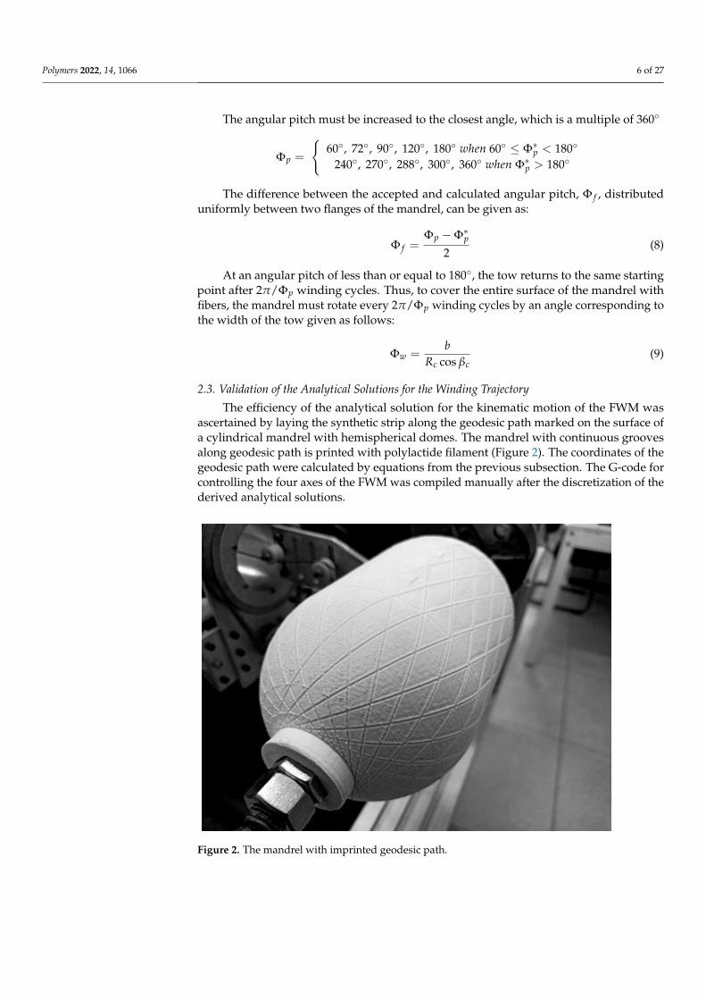
The efficiency of the analytical solution for the kinematic motion of the FWM wasascertained by laying the synthetic strip along the geodesic path marked on the surface ofa cylindrical mandrel with hemispherical domes. The mandrel with continuous groovesalong geodesic path is printed with polylactide filament (Figure 2). The coordinates of thegeodesic path were calculated by equations from the previous subsection. The G-code forcontrolling the four axes of the FWM was compiled manually after the discretization of thederived analytical solutions.
Polymers 2022, 14, x FOR PEER REVIEW 6 of 27
The turn-around angle for one winding cycle Φ can be computed as: Φ = 2Φ + 4Φ (6)
The fiber crosses any latitude of the mandrel twice every winding cycle. For the ob-tained value Φ not a multiple of 2π (360°), the tow after one winding cycle returns to the same latitude from which it started its trajectory but does not coincide with the starting point. The angular pitch of winding Φ∗ is defined as an angle measured in the direction of the mandrel rotation between the starting and final points of one winding cycle and can be described mathematically as: Φ∗ = Φ − 2𝜋 ∙ 𝑖𝑛𝑡𝑒𝑔𝑒𝑟 Φ2𝜋 (7)
The angular pitch must be increased to the closest angle, which is a multiple of 360° Φ = 60°, 72°, 90°, 120°, 180° 𝑤ℎ𝑒𝑛 60° ≤ 𝛷∗ < 180°240°, 270°, 288°, 300°, 360° 𝑤ℎ𝑒𝑛 𝛷∗ > 180°
The difference between the accepted and calculated angular pitch, Φ , distributed uniformly between two flanges of the mandrel, can be given as: Φ = Φ − Φ∗2 (8)
At an angular pitch of less than or equal to 180°, the tow returns to the same starting point after 2𝜋/Φ winding cycles. Thus, to cover the entire surface of the mandrel with fibers, the mandrel must rotate every 2𝜋/Φ winding cycles by an angle corresponding to the width of the tow given as follows: Φ = 𝑏𝑅 cos 𝛽 (9)
2.3. Validation of the Analytical Solutions for the Winding Trajectory The efficiency of the analytical solution for the kinematic motion of the FWM was
ascertained by laying the synthetic strip along the geodesic path marked on the surface of a cylindrical mandrel with hemispherical domes. The mandrel with continuous grooves along geodesic path is printed with polylactide filament (Figure 2). The coordinates of the geodesic path were calculated by equations from the previous subsection. The G-code for controlling the four axes of the FWM was compiled manually after the discretization of the derived analytical solutions.
Figure 2. The mandrel with imprinted geodesic path. Figure 2. The mandrel with imprinted geodesic path.

Polymers 2022, 14, 1066 7 of 27
2.4. Manufacturing and Characterization of the Casing
The casing is wound over two types of mandrel with the same geometry (Rc = 60 mm,rp = 21 mm, and Lc = 160 mm). The mandrel for the cold-curing epoxy composition LY5052is made from polyethylene terephthalate glycolmodified (PETG) filament by 3D printing.Water-soluble mandrel from sand/polyvinyl alcohol composition [35] was used for theheat-curing epoxy resin LY1564. The sand components of the mandrel (Figure 3) weremolded together with aluminum bushings in low-cost silicon molds. After solidification inan electric oven, these were mounted on a threaded shaft (Figure 4) with other componentsof the mandrel, namely heat insulators and flanges. The sand mandrel was washed outwith hot water after manufacturing and curing the casing.
Polymers 2022, 14, x FOR PEER REVIEW 7 of 27
2.4. Manufacturing and Characterization of the Casing The casing is wound over two types of mandrel with the same geometry (Rc = 60 mm,
rp = 21 mm, and Lc = 160 mm). The mandrel for the cold-curing epoxy composition LY5052 is made from polyethylene terephthalate glycolmodified (PETG) filament by 3D printing. Water-soluble mandrel from sand/polyvinyl alcohol composition [35] was used for the heat-curing epoxy resin LY1564. The sand components of the mandrel (Figure 3) were molded together with aluminum bushings in low-cost silicon molds. After solidification in an electric oven, these were mounted on a threaded shaft (Figure 4) with other compo-nents of the mandrel, namely heat insulators and flanges. The sand mandrel was washed out with hot water after manufacturing and curing the casing.
Figure 3. Solidified sand components kit for manufacturing a soluble mandrel.
Figure 4. The sand mandrel assembled on a threaded shaft with flanges and heat insulators.
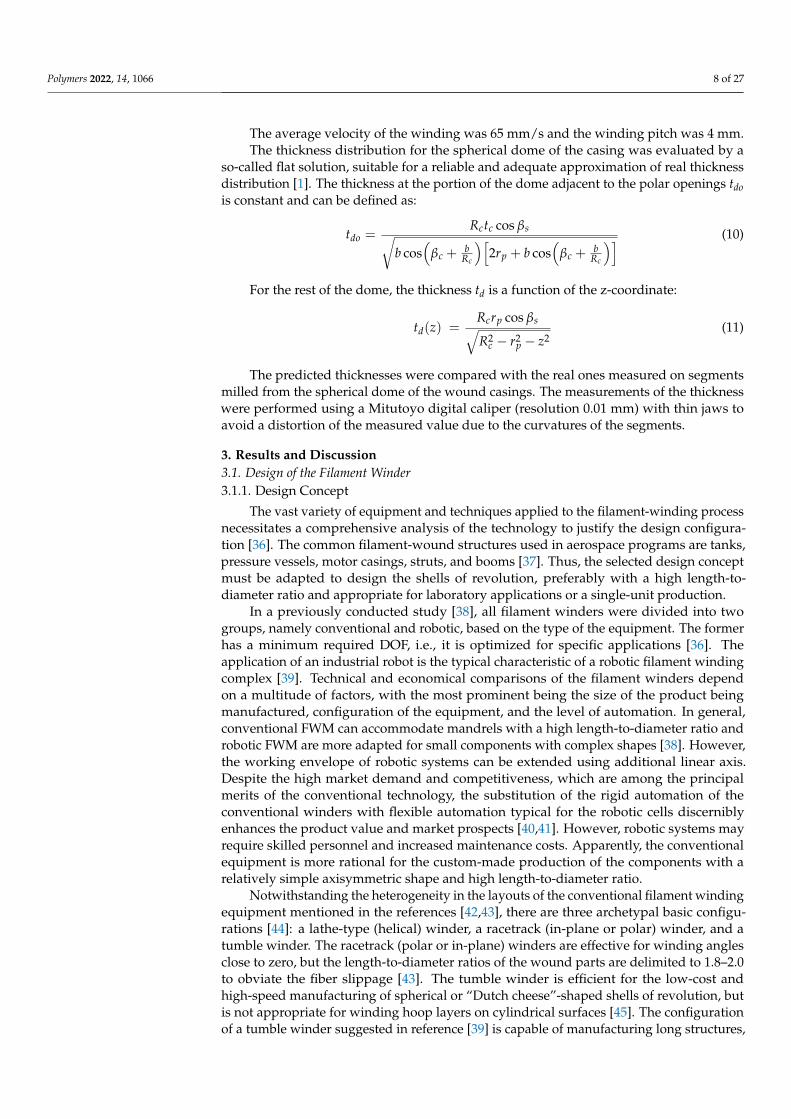
The average velocity of the winding was 65 mm/s and the winding pitch was 4 mm. The thickness distribution for the spherical dome of the casing was evaluated by a
so-called flat solution, suitable for a reliable and adequate approximation of real thickness distribution [1]. The thickness at the portion of the dome adjacent to the polar openings 𝑡𝑑𝑜 is constant and can be defined as: 𝑡 = 𝑅 𝑡 cos 𝛽𝑏 cos(𝛽 + 𝑏𝑅 ) 2𝑟 + 𝑏 cos 𝛽 + 𝑏𝑅 (10)
For the rest of the dome, the thickness 𝑡𝑑 is a function of the z-coordinate: 𝑡 (𝑧) = 𝑅 𝑟 cos 𝛽𝑅 − 𝑟 − 𝑧 (11)
Figure 3. Solidified sand components kit for manufacturing a soluble mandrel.
Polymers 2022, 14, x FOR PEER REVIEW 7 of 27
2.4. Manufacturing and Characterization of the Casing The casing is wound over two types of mandrel with the same geometry (Rc = 60 mm,
rp = 21 mm, and Lc = 160 mm). The mandrel for the cold-curing epoxy composition LY5052 is made from polyethylene terephthalate glycolmodified (PETG) filament by 3D printing. Water-soluble mandrel from sand/polyvinyl alcohol composition [35] was used for the heat-curing epoxy resin LY1564. The sand components of the mandrel (Figure 3) were molded together with aluminum bushings in low-cost silicon molds. After solidification in an electric oven, these were mounted on a threaded shaft (Figure 4) with other compo-nents of the mandrel, namely heat insulators and flanges. The sand mandrel was washed out with hot water after manufacturing and curing the casing.
Figure 3. Solidified sand components kit for manufacturing a soluble mandrel.
Figure 4. The sand mandrel assembled on a threaded shaft with flanges and heat insulators.
The average velocity of the winding was 65 mm/s and the winding pitch was 4 mm. The thickness distribution for the spherical dome of the casing was evaluated by a
so-called flat solution, suitable for a reliable and adequate approximation of real thickness distribution [1]. The thickness at the portion of the dome adjacent to the polar openings 𝑡𝑑𝑜 is constant and can be defined as: 𝑡 = 𝑅 𝑡 cos 𝛽𝑏 cos(𝛽 + 𝑏𝑅 ) 2𝑟 + 𝑏 cos 𝛽 + 𝑏𝑅 (10)
For the rest of the dome, the thickness 𝑡𝑑 is a function of the z-coordinate: 𝑡 (𝑧) = 𝑅 𝑟 cos 𝛽𝑅 − 𝑟 − 𝑧 (11)
Figure 4. The sand mandrel assembled on a threaded shaft with flanges and heat insulators.
Polymers 2022, 14, 1066 8 of 27
The average velocity of the winding was 65 mm/s and the winding pitch was 4 mm.The thickness distribution for the spherical dome of the casing was evaluated by a
so-called flat solution, suitable for a reliable and adequate approximation of real thicknessdistribution [1]. The thickness at the portion of the dome adjacent to the polar openings tdois constant and can be defined as:
tdo =Rctc cos βs√
b cos(
βc +b
Rc
)[2rp + b cos
(βc +
bRc
)] (10)
For the rest of the dome, the thickness td is a function of the z-coordinate:
td(z) =Rcrp cos βs√R2
c − r2p − z2
(11)
The predicted thicknesses were compared with the real ones measured on segmentsmilled from the spherical dome of the wound casings. The measurements of the thicknesswere performed using a Mitutoyo digital caliper (resolution 0.01 mm) with thin jaws toavoid a distortion of the measured value due to the curvatures of the segments.
3. Results and Discussion3.1. Design of the Filament Winder3.1.1. Design Concept
The vast variety of equipment and techniques applied to the filament-winding processnecessitates a comprehensive analysis of the technology to justify the design configura-tion [36]. The common filament-wound structures used in aerospace programs are tanks,pressure vessels, motor casings, struts, and booms [37]. Thus, the selected design conceptmust be adapted to design the shells of revolution, preferably with a high length-to-diameter ratio and appropriate for laboratory applications or a single-unit production.
In a previously conducted study [38], all filament winders were divided into twogroups, namely conventional and robotic, based on the type of the equipment. The formerhas a minimum required DOF, i.e., it is optimized for specific applications [36]. Theapplication of an industrial robot is the typical characteristic of a robotic filament windingcomplex [39]. Technical and economical comparisons of the filament winders dependon a multitude of factors, with the most prominent being the size of the product beingmanufactured, configuration of the equipment, and the level of automation. In general,conventional FWM can accommodate mandrels with a high length-to-diameter ratio androbotic FWM are more adapted for small components with complex shapes [38]. However,the working envelope of robotic systems can be extended using additional linear axis.Despite the high market demand and competitiveness, which are among the principalmerits of the conventional technology, the substitution of the rigid automation of theconventional winders with flexible automation typical for the robotic cells discerniblyenhances the product value and market prospects [40,41]. However, robotic systems mayrequire skilled personnel and increased maintenance costs. Apparently, the conventionalequipment is more rational for the custom-made production of the components with arelatively simple axisymmetric shape and high length-to-diameter ratio.
Notwithstanding the heterogeneity in the layouts of the conventional filament windingequipment mentioned in the references [42,43], there are three archetypal basic configu-rations [44]: a lathe-type (helical) winder, a racetrack (in-plane or polar) winder, and atumble winder. The racetrack (polar or in-plane) winders are effective for winding anglesclose to zero, but the length-to-diameter ratios of the wound parts are delimited to 1.8–2.0to obviate the fiber slippage [43]. The tumble winder is efficient for the low-cost andhigh-speed manufacturing of spherical or “Dutch cheese”-shaped shells of revolution, butis not appropriate for winding hoop layers on cylindrical surfaces [45]. The configurationof a tumble winder suggested in reference [39] is capable of manufacturing long structures,
Polymers 2022, 14, 1066 9 of 27
but imposes demanding requirements on the rigidity of the mandrel holding structure.The lathe-type winders are the most prevalent and conventional machines with somelimitations in the range of extremely small winding angles. Other disadvantages of thelathe-type machines include high delivery eye translations and accelerations in comparisonwith the racetrack or tumble winders. However, none of these drawbacks preclude theextensive use of the lathe-type configuration for manufacturing the axisymmetric aerospacestructures mentioned above. Another cogent reason that renders a conventional lathe-typemachine more appropriate for the applications presented here is the correlation of its costwith the number of DOF [36]. The sufficient number of DOF for the filament winder isdetermined by a number of independent parameters that describe the relative orientationbetween delivery eye and mandrel [39]. The greater the number of DOF the winder has,the more intricate the wound part and the control system are anticipated to be [46]. By theadoption of the conventional methods of linear algebra, it was shown that FWM must haveat least six DOF [39]. However, for tow-winding, the sufficient number of DOF is four, asthe twisting of the tow is of less importance. For the axisymmetric mandrel, some of theindependent parameters might be constant. For instance, the distance between the surfaceof the mandrel and delivery tool might be constant for the helical tow-winding around thecylindrical mandrel. Thus, the number of sufficient DOF decreases to two. Componentsthat are more complex than a cylinder can be wound with only two DOF [29]. It is worthnoting that a low number of DOF requires a more elaborate calculation of the deliveryeye trajectory and speed [31]. An additional DOF eliminates unrealistic translations in thewinder components [32]. Consequently, the configuration with four DOF was selected forthe filament winder under consideration.
From the three impregnation methods described in [47], only wet/dry winding has awidespread application for aerospace components. For occasional non-batch applications,the wet winding method is more advantageous when compared with the dry method forthe following reasons [47,48]: (1) enhanced variety of fiber/resin combinations; (2) lowerprobability of fiber damage; (3) longer shelf life for resins, while prepregs must be stored ina freezer for a limited period; (4) room temperature cure; and (5) lower cost. Moreover, thewet winding equipment can be easily readjusted for prepreg winding.
The latter is considered available and straightforward from two roving impregnationsystems, a dip-type and a drum-type bath system [49]. Notwithstanding the poor controlover the fiber volume ratio that leads to an excess of resin, the drum-type bath systems havea wide application in industry. A doctor blade device may adjust the required resin-filmthickness on the drum, restricting the amount of resin that can enter the polymer composite.Thus, the proposed low-cost technology for the irregular or laboratory production of thepolymer composite shells of revolution with a high length-to-diameter ratio is based ona lathe-type filament winder with four DOF and a proper bath-type resin impregnationsystem. This low-cost concept is predicated on the extensive use of standard aluminum andsteel profiles for the structural frames, off-the-shelf mechanical and electronic components,3D-printed parts, obsolete personal computer and cheap software for the control system,and manual generation of the control codes supported by analytical equations. In addition,there are no complex adaptive tensioning systems. The pretension is provided by a simpletensioning mechanism, such as rotating scissor bars with manual adjustment [50]. Thevariation in fiber tension can be minimized by the appropriate feed-eye trajectory [31].
3.1.2. Description of the Filament Winder
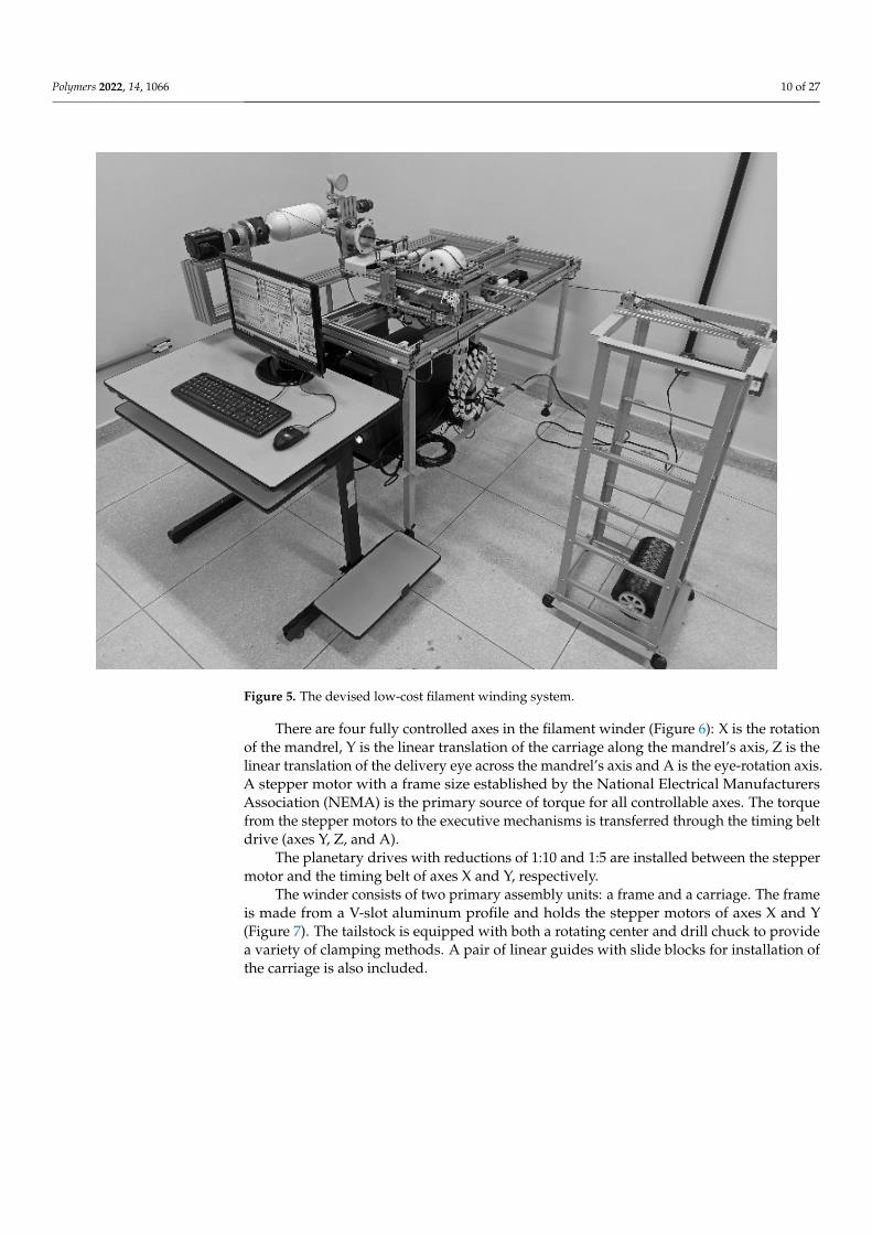
The system for the filament winding comprises the main units formed by the winder,the stationary creel, and the operator’s workplace (Figure 5). The stationary creel is a carbonsteel shelf that holds a maximum of four fiber packages on a cardboard tube. The operator’sworkplace is a desk equipped with a monitor, a keyboard, and a mouse. The winder wasinstalled on a carbon steel stand holding cabinets for the control system, protected fromresin leakage by a silicone layer.
Polymers 2022, 14, 1066 10 of 27Polymers 2022, 14, x FOR PEER REVIEW 10 of 27
Figure 5. The devised low-cost filament winding system.
There are four fully controlled axes in the filament winder (Figure 6): X is the rotation of the mandrel, Y is the linear translation of the carriage along the mandrel’s axis, Z is the linear translation of the delivery eye across the mandrel’s axis and A is the eye-rotation axis. A stepper motor with a frame size established by the National Electrical Manufac-turers Association (NEMA) is the primary source of torque for all controllable axes. The torque from the stepper motors to the executive mechanisms is transferred through the timing belt drive (axes Y, Z, and A).
Figure 5. The devised low-cost filament winding system.
There are four fully controlled axes in the filament winder (Figure 6): X is the rotationof the mandrel, Y is the linear translation of the carriage along the mandrel’s axis, Z is thelinear translation of the delivery eye across the mandrel’s axis and A is the eye-rotation axis.A stepper motor with a frame size established by the National Electrical ManufacturersAssociation (NEMA) is the primary source of torque for all controllable axes. The torquefrom the stepper motors to the executive mechanisms is transferred through the timing beltdrive (axes Y, Z, and A).
The planetary drives with reductions of 1:10 and 1:5 are installed between the steppermotor and the timing belt of axes X and Y, respectively.
The winder consists of two primary assembly units: a frame and a carriage. The frameis made from a V-slot aluminum profile and holds the stepper motors of axes X and Y(Figure 7). The tailstock is equipped with both a rotating center and drill chuck to providea variety of clamping methods. A pair of linear guides with slide blocks for installation ofthe carriage is also included.

Polymers 2022, 14, 1066 11 of 27Polymers 2022, 14, x FOR PEER REVIEW 11 of 27
Figure 6. Kinematic diagram of the winder: N·m—unit for torque; NEMA—motor frame size; 1:5 and 1:10—reduction ratios; z—number of teeth.
The planetary drives with reductions of 1:10 and 1:5 are installed between the stepper motor and the timing belt of axes X and Y, respectively.
Figure 6. Kinematic diagram of the winder: N·m—unit for torque; NEMA—motor frame size; 1:5and 1:10—reduction ratios; z—number of teeth.
Polymers 2022, 14, 1066 12 of 27
Polymers 2022, 14, x FOR PEER REVIEW 12 of 27
The winder consists of two primary assembly units: a frame and a carriage. The frame is made from a V-slot aluminum profile and holds the stepper motors of axes X and Y (Figure 7). The tailstock is equipped with both a rotating center and drill chuck to provide a variety of clamping methods. A pair of linear guides with slide blocks for installation of the carriage is also included.
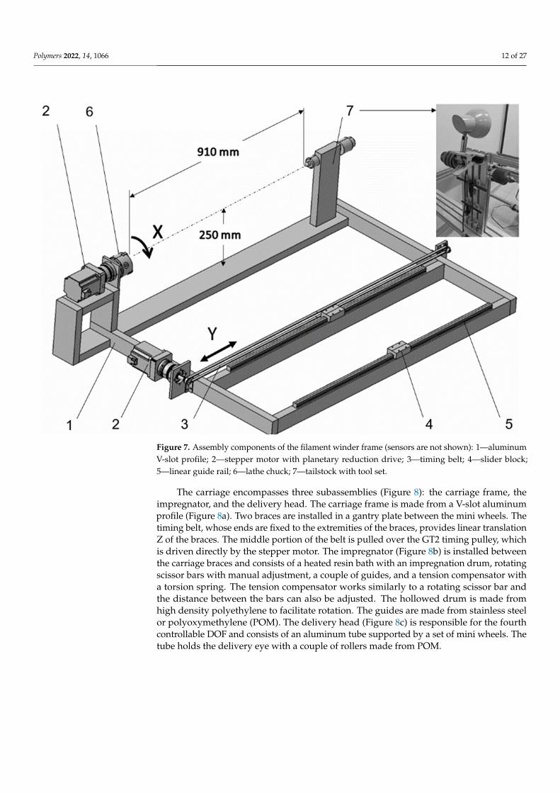
Figure 7. Assembly components of the filament winder frame (sensors are not shown): 1—alumi-num v-slot profile; 2—stepper motor with planetary reduction drive; 3—timing belt; 4—slider block; 5—linear guide rail; 6—lathe chuck; 7—tailstock with tool set.
The carriage encompasses three subassemblies (Figure 8): the carriage frame, the im-pregnator, and the delivery head. The carriage frame is made from a V-slot aluminum profile (Figure 8a). Two braces are installed in a gantry plate between the mini wheels. The timing belt, whose ends are fixed to the extremities of the braces, provides linear translation Z of the braces. The middle portion of the belt is pulled over the GT2 timing pulley, which is driven directly by the stepper motor. The impregnator (Figure 8b) is in-stalled between the carriage braces and consists of a heated resin bath with an impregna-tion drum, rotating scissor bars with manual adjustment, a couple of guides, and a tension compensator with a torsion spring. The tension compensator works similarly to a rotating scissor bar and the distance between the bars can also be adjusted. The hollowed drum is made from high density polyethylene to facilitate rotation. The guides are made from stainless steel or polyoxymethylene (POM). The delivery head (Figure 8c) is responsible for the fourth controllable DOF and consists of an aluminum tube supported by a set of mini wheels. The tube holds the delivery eye with a couple of rollers made from POM.
Figure 7. Assembly components of the filament winder frame (sensors are not shown): 1—aluminumV-slot profile; 2—stepper motor with planetary reduction drive; 3—timing belt; 4—slider block;5—linear guide rail; 6—lathe chuck; 7—tailstock with tool set.
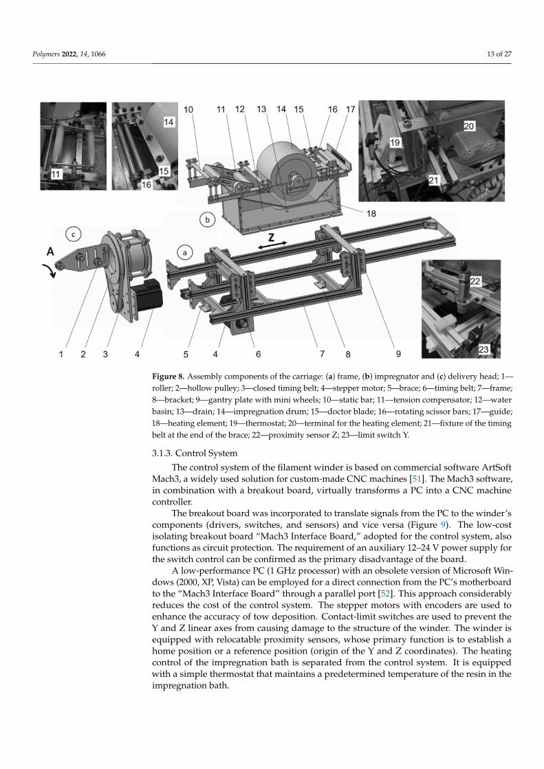
The carriage encompasses three subassemblies (Figure 8): the carriage frame, theimpregnator, and the delivery head. The carriage frame is made from a V-slot aluminumprofile (Figure 8a). Two braces are installed in a gantry plate between the mini wheels. Thetiming belt, whose ends are fixed to the extremities of the braces, provides linear translationZ of the braces. The middle portion of the belt is pulled over the GT2 timing pulley, whichis driven directly by the stepper motor. The impregnator (Figure 8b) is installed betweenthe carriage braces and consists of a heated resin bath with an impregnation drum, rotatingscissor bars with manual adjustment, a couple of guides, and a tension compensator witha torsion spring. The tension compensator works similarly to a rotating scissor bar andthe distance between the bars can also be adjusted. The hollowed drum is made fromhigh density polyethylene to facilitate rotation. The guides are made from stainless steelor polyoxymethylene (POM). The delivery head (Figure 8c) is responsible for the fourthcontrollable DOF and consists of an aluminum tube supported by a set of mini wheels. Thetube holds the delivery eye with a couple of rollers made from POM.
Polymers 2022, 14, 1066 13 of 27
Polymers 2022, 14, x FOR PEER REVIEW 13 of 27
Figure 8. Assembly components of the carriage: (a) frame, (b) impregnator and (c) delivery head; 1—roller; 2—hollow pulley; 3—closed timing belt; 4—stepper motor; 5—brace; 6—timing belt; 7—frame; 8—bracket; 9—gantry plate with mini wheels; 10—static bar; 11—tension compensator; 12—water basin; 13—drain; 14—impregnation drum; 15—doctor blade; 16—rotating scissor bars; 17—guide; 18—heating element; 19—thermostat; 20—terminal for the heating element; 21—fixture of the timing belt at the end of the brace; 22—proximity sensor Z; 23—limit switch Y.
3.1.3. Control System The control system of the filament winder is based on commercial software ArtSoft
Mach3, a widely used solution for custom-made CNC machines [51]. The Mach3 software, in combination with a breakout board, virtually transforms a PC into a CNC machine controller.
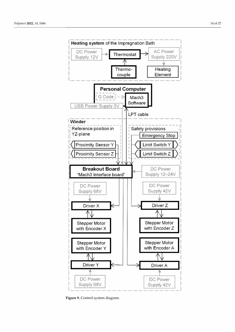
The breakout board was incorporated to translate signals from the PC to the winder’s components (drivers, switches, and sensors) and vice versa (Figure 9). The low-cost iso-lating breakout board “Mach3 Interface Board,” adopted for the control system, also func-tions as circuit protection. The requirement of an auxiliary 12–24 V power supply for the switch control can be confirmed as the primary disadvantage of the board.
A low-performance PC (1 GHz processor) with an obsolete version of Microsoft Win-dows (2000, XP, Vista) can be employed for a direct connection from the PC’s motherboard to the “Mach3 Interface Board” through a parallel port [52]. This approach considerably reduces the cost of the control system. The stepper motors with encoders are used to en-hance the accuracy of tow deposition. Contact-limit switches are used to prevent the Y and Z linear axes from causing damage to the structure of the winder. The winder is equipped with relocatable proximity sensors, whose primary function is to establish a home position or a reference position (origin of the Y and Z coordinates). The heating control of the impregnation bath is separated from the control system. It is equipped with a simple thermostat that maintains a predetermined temperature of the resin in the im-pregnation bath.
Figure 8. Assembly components of the carriage: (a) frame, (b) impregnator and (c) delivery head; 1—roller; 2—hollow pulley; 3—closed timing belt; 4—stepper motor; 5—brace; 6—timing belt; 7—frame;8—bracket; 9—gantry plate with mini wheels; 10—static bar; 11—tension compensator; 12—waterbasin; 13—drain; 14—impregnation drum; 15—doctor blade; 16—rotating scissor bars; 17—guide;18—heating element; 19—thermostat; 20—terminal for the heating element; 21—fixture of the timingbelt at the end of the brace; 22—proximity sensor Z; 23—limit switch Y.
3.1.3. Control System
The control system of the filament winder is based on commercial software ArtSoftMach3, a widely used solution for custom-made CNC machines [51]. The Mach3 software,in combination with a breakout board, virtually transforms a PC into a CNC machinecontroller.
The breakout board was incorporated to translate signals from the PC to the winder’scomponents (drivers, switches, and sensors) and vice versa (Figure 9). The low-costisolating breakout board “Mach3 Interface Board,” adopted for the control system, alsofunctions as circuit protection. The requirement of an auxiliary 12–24 V power supply forthe switch control can be confirmed as the primary disadvantage of the board.
A low-performance PC (1 GHz processor) with an obsolete version of Microsoft Win-dows (2000, XP, Vista) can be employed for a direct connection from the PC’s motherboardto the “Mach3 Interface Board” through a parallel port [52]. This approach considerablyreduces the cost of the control system. The stepper motors with encoders are used toenhance the accuracy of tow deposition. Contact-limit switches are used to prevent theY and Z linear axes from causing damage to the structure of the winder. The winder isequipped with relocatable proximity sensors, whose primary function is to establish ahome position or a reference position (origin of the Y and Z coordinates). The heatingcontrol of the impregnation bath is separated from the control system. It is equippedwith a simple thermostat that maintains a predetermined temperature of the resin in theimpregnation bath.
Polymers 2022, 14, 1066 14 of 27Polymers 2022, 14, x FOR PEER REVIEW 14 of 27
Figure 9. Control system diagram.
3.2. Trajectory of the Delivery Eye To place the tow along the geodesic path when the distance between the delivery eye
and the mandrel surface is not zero, equations for the coordinates of the delivery-eye tra-jectory are indispensable.
Figure 9. Control system diagram.
Polymers 2022, 14, 1066 15 of 27
3.2. Trajectory of the Delivery Eye
To place the tow along the geodesic path when the distance between the deliveryeye and the mandrel surface is not zero, equations for the coordinates of the delivery-eyetrajectory are indispensable.
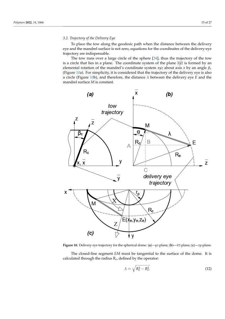
The tow runs over a large circle of the sphere [34], thus the trajectory of the towis a circle that lies in a plane. The coordinate system of the plane xyz is formed by anelemental rotation of the mandrel’s coordinate system xyz about axis x by an angle βc(Figure 10a). For simplicity, it is considered that the trajectory of the delivery eye is alsoa circle (Figure 10b), and therefore, the distance λ between the delivery eye E and themandrel surface M is constant.
Polymers 2022, 14, x FOR PEER REVIEW 15 of 27
The tow runs over a large circle of the sphere [34], thus the trajectory of the tow is a circle that lies in a plane. The coordinate system of the plane ��𝑦𝑧 is formed by an ele-mental rotation of the mandrel’s coordinate system xyz about axis x by an angle 𝛽 (Fig-ure 10a). For simplicity, it is considered that the trajectory of the delivery eye is also a circle (Figure 10b), and therefore, the distance λ between the delivery eye E and the man-drel surface M is constant.
Figure 10. Delivery eye trajectory for the spherical dome: (a)—yz-plane; (b)—xz-plane; (c)—xy-plane.
The closed-line segment EM must be tangential to the surface of the dome. It is cal-culated through the radius Re, defined by the operator: 𝜆 = 𝑅 − 𝑅 . (12)
The coordinates of the delivery eye in the coordinate system ��𝑦𝑧 are defined through the variable angle α depicted in Figure 10b: �� = 𝑀𝐶 − 𝑀𝐵 = 𝑅 𝑐𝑜𝑠 𝛼 − 𝜆 𝑠𝑖𝑛 𝛼, 𝑦 = 0, 𝑧 = 𝐴𝐵 − 𝐵𝐸 = 𝑅 𝑠𝑖𝑛 𝛼 − 𝜆 𝑐𝑜𝑠 𝛼. (13)
The coordinates of the delivery eye in the mandrel’s coordinate system 𝑥𝑦𝑧 are de-fined by the following well-known equations of linear algebra: 𝑥 = �� , 𝑦 = 𝑦 𝑐𝑜𝑠 𝛽 − 𝑧 𝑠𝑖𝑛 𝛽 , (14)
Figure 10. Delivery eye trajectory for the spherical dome: (a)—yz-plane; (b)—xz-plane; (c)—xy-plane.
The closed-line segment EM must be tangential to the surface of the dome. It iscalculated through the radius Re, defined by the operator:
λ =√
R2e − R2
c . (12)

Polymers 2022, 14, 1066 16 of 27
The coordinates of the delivery eye in the coordinate system xyz are defined throughthe variable angle α depicted in Figure 10b:
xe = MC−MB = Rc cos α− λ sin α,ye = 0,
ze = AB− BE = Rc sin α− λ cos α.(13)
The coordinates of the delivery eye in the mandrel’s coordinate system xyz are definedby the following well-known equations of linear algebra:
xe = xe,ye = ye cos βc − ze sin βc,ze = ye sin βc + ze cos βc.
(14)
Substituting Equations (13) into (14) provides
xe = Rc cos α− λ sin α,ye = −
rpRc(Rc sin α + λ cos α),
ze =
√Rc2−rp2
Rc(Rc sin α + λ cos α).
(15)
The coordinates of the delivery eye are obtained through controllable DOF (i.e., in thecoordinate system of the winder), which are determined from Figure 10c in terms of thecoordinates in the mandrel’s coordinate system xyz.
X = tan−1 yexe
,Y = ze,
Z =√
xe2 + ye2.(16)
Finally, substituting Equations (15) into (16) provides the formulas for the delivery eyetrajectory as a function of α
X = tan−1[− rp(Rc sin α+λ cos α)
Rc(Rc cos α−λ sin α)
],
Y =
√Rc2−rp2
Rc(Rc sin α + λ cos α),
Z = ((Rc cos α− λ sin α)2 +(
rpRc
)2(Rc sin α + λ cos α)2)
1/2.
(17)
An involute screw surface analytically described in a Cartesian coordinate system [53]provided the coordinates of the delivery eye trajectory for the cylindrical part of the mandrel(Figure 11):
xi = Rc cos θ + λ sin βc sin θ,yi = Rc sin θ − λ sin βc cos θ,
zi = Rcθ cot βc − λ cos βc.(18)
Here, angle θ is a function of the axial coordinate z:
θ =z tan βc
Rc. (19)
The delivery eye trajectory is given through controllable DOF of the winder as follows:
X = z tan βcRc
,Y = z,
Z = ((Rc cos θ + λ sin βc sin θ)2 + (Rc sin θ − λ sin βc cos θ)2)1/2
(20)

Polymers 2022, 14, 1066 17 of 27Polymers 2022, 14, x FOR PEER REVIEW 17 of 27
Figure 11. Delivery eye trajectory for the cylinder.
Here, angle 𝜃 is a function of the axial coordinate z: 𝜃 = 𝑧 tan 𝛽𝑅 . (19)
The delivery eye trajectory is given through controllable DOF of the winder as fol-lows: 𝑋 = 𝑧 tan 𝛽𝑅 , 𝑌 = 𝑧, 𝑍 = ((𝑅 cos 𝜃 + 𝜆 sin 𝛽 sin 𝜃) + (𝑅 sin 𝜃 − 𝜆 sin 𝛽 cos 𝜃) ) /
(20)
The angle of the eye rotation axis A depends on the winding angle, such that the axis of the roller must be perpendicular to the direction of the tow: 𝐴 = 𝜋2 − 𝛽 (21)
Here, β is calculated by Equation (3) for the hemispherical dome and by Equation (1) for the cylinder.
3.3. Validation of the Analytical Solution for the Winding Trajectory of the FWM The length of the cylindrical part of the mandrel Lc = 84.1 mm is chosen in such a
manner that the imprinted grooves are continuous along the geodesic path (see Figure 2) and form a closed loop.
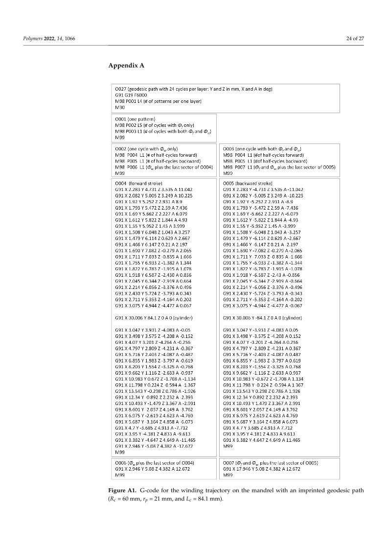
The winding parameters (Table 3 and Figure 12) yield the same pattern on the surface of the mandrel for both the tow and the grooves. The trajectories of the delivery eye and the tow calculated for the constant distance λ = 67 mm by Equations (17) and (20) are illustrated in Figure 13. The wound pattern obtained by the calculated trajectories (the generated G-code is given in Appendix A) corresponds to the pattern of the imprinted grooves (Figure 14), which, in turn, substantiates the reliability and effectiveness of the suggested equations.
Figure 11. Delivery eye trajectory for the cylinder.
The angle of the eye rotation axis A depends on the winding angle, such that the axisof the roller must be perpendicular to the direction of the tow:
A =π
2− β (21)
Here, β is calculated by Equation (3) for the hemispherical dome and by Equation (1)for the cylinder.
3.3. Validation of the Analytical Solution for the Winding Trajectory of the FWM
The length of the cylindrical part of the mandrel Lc = 84.1 mm is chosen in such amanner that the imprinted grooves are continuous along the geodesic path (see Figure 2)and form a closed loop.
The winding parameters (Table 3 and Figure 12) yield the same pattern on the surfaceof the mandrel for both the tow and the grooves. The trajectories of the delivery eye andthe tow calculated for the constant distance λ = 67 mm by Equations (17) and (20) areillustrated in Figure 13. The wound pattern obtained by the calculated trajectories (thegenerated G-code is given in Appendix A) corresponds to the pattern of the imprintedgrooves (Figure 14), which, in turn, substantiates the reliability and effectiveness of thesuggested equations.
Table 3. The winding parameters for the mandrel with imprinted geodesic path, in degrees.
βc Φc Φs Φ1 Φp Φf Φw
20.5 15 90 420 0 0 15
Polymers 2022, 14, 1066 18 of 27
Polymers 2022, 14, x FOR PEER REVIEW 18 of 27
Table 3. The winding parameters for the mandrel with imprinted geodesic path, in degrees.
βc Φc Φs Φ1 Φp Φf Φw 20.5 15 90 420 0 0 15
Figure 12. Winding angle on the spherical dome.
Figure 13. Calculated trajectories of the delivery eye and the tow depicted for half of the mandrel (λ = constant).
Figure 12. Winding angle on the spherical dome.
Polymers 2022, 14, x FOR PEER REVIEW 18 of 27
Table 3. The winding parameters for the mandrel with imprinted geodesic path, in degrees.
βc Φc Φs Φ1 Φp Φf Φw 20.5 15 90 420 0 0 15
Figure 12. Winding angle on the spherical dome.
Figure 13. Calculated trajectories of the delivery eye and the tow depicted for half of the mandrel (λ = constant).
Figure 13. Calculated trajectories of the delivery eye and the tow depicted for half of the mandrel(λ = constant).
Polymers 2022, 14, 1066 19 of 27Polymers 2022, 14, x FOR PEER REVIEW 19 of 27
Figure 14. Wound pattern on the surface of the mandrel with the imprinted geodesic path.
As the geodesic trajectory has been calculated for a filament with an infinitesimally small width, a strip with a width of 3.5 mm partially covers the surface of the flange. Overlap can be eliminated by decreasing the opening radius in the calculations of the ge-odesic path or can be regulated with a slight displacement of the initial position of the delivery eye out of the mandrel. However, deviations from the geodesic path are inevita-ble in the latter case.
3.4. Characterization of the Casings The winding parameters used for the manufacturing of the casings are the same for
all of the double helical plies in the layup (Table 4 and Figure 12). The winding pitch for the 90° ply is 4 mm.
Table 4. The winding parameters for the mandrel with imprinted geodesic path, in degrees.
βc Φc Φs Φ1 Φp Φf Φw 20.5 57.1 90 474.2 120 2.91 4.08
Before winding the casings with carbon filament impregnated by two types of the epoxy resin, the calculated trajectory of the delivery eye was already successfully verified for the double angle-ply layer with use of the synthetic strip (Figure 15). The winding of one double angle-ply layer required approximately 16 min at the maximum speed estab-lished in the G-code, which is equal to 6000 mm/min for the linear translations (Z and Y axes) and 6000 degrees/min for the rotational motion (X and A axes).
Figure 14. Wound pattern on the surface of the mandrel with the imprinted geodesic path.
As the geodesic trajectory has been calculated for a filament with an infinitesimallysmall width, a strip with a width of 3.5 mm partially covers the surface of the flange.Overlap can be eliminated by decreasing the opening radius in the calculations of thegeodesic path or can be regulated with a slight displacement of the initial position of thedelivery eye out of the mandrel. However, deviations from the geodesic path are inevitablein the latter case.
3.4. Characterization of the Casings
The winding parameters used for the manufacturing of the casings are the same forall of the double helical plies in the layup (Table 4 and Figure 12). The winding pitch forthe 90◦ ply is 4 mm.
Table 4. The winding parameters for the mandrel with imprinted geodesic path, in degrees.
βc Φc Φs Φ1 Φp Φf Φw
20.5 57.1 90 474.2 120 2.91 4.08
Before winding the casings with carbon filament impregnated by two types of theepoxy resin, the calculated trajectory of the delivery eye was already successfully verifiedfor the double angle-ply layer with use of the synthetic strip (Figure 15). The winding of onedouble angle-ply layer required approximately 16 min at the maximum speed establishedin the G-code, which is equal to 6000 mm/min for the linear translations (Z and Y axes)and 6000 degrees/min for the rotational motion (X and A axes).
Polymers 2022, 14, 1066 20 of 27Polymers 2022, 14, x FOR PEER REVIEW 20 of 27
Figure 15. Wound pattern of the double helical layer verified with synthetic strip (left) and the car-bon/epoxy casing LY5052 [±20.53/90] after curing (right).
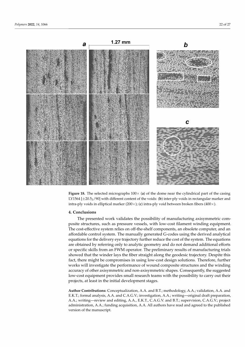
The thicknesses measured along the dome wall of the wound casings with different resin compositions and stacking sequences are in good agreement with the distribution predicted by the flat solution, except for the portion near the flange (Figure 16), as a result of the varying compaction performance of the composite material at the dome. Notwith-standing the significant amount of resin drips from the casing surface before the curing is completed, a great volume of resin is trapped inside the layer (Figure 17). At the flange, there is a huge zone covered in resin and there are multiple pores. In the cylindrical part, the trapped resin is between the plies and there are few pores. The most porous casing is made from composition LY1564 (Figure 18). The size and the distribution of voids can be attributed to the absence of an adaptive tensioner of the tow in the developed FWM and excessive resin content inherent to the drum-type bath impregnation system. In the latter case, the voids originate from entrapped air bubbles or from more complex local curing effects described in the literature [54].
Figure 16. Thickness distribution in the dome of the wound casings.
Figure 15. Wound pattern of the double helical layer verified with synthetic strip (left) and thecarbon/epoxy casing LY5052 [±20.53/90] after curing (right).
The thicknesses measured along the dome wall of the wound casings with differentresin compositions and stacking sequences are in good agreement with the distributionpredicted by the flat solution, except for the portion near the flange (Figure 16), as aresult of the varying compaction performance of the composite material at the dome.Notwithstanding the significant amount of resin drips from the casing surface before thecuring is completed, a great volume of resin is trapped inside the layer (Figure 17). At theflange, there is a huge zone covered in resin and there are multiple pores. In the cylindricalpart, the trapped resin is between the plies and there are few pores. The most porous casingis made from composition LY1564 (Figure 18). The size and the distribution of voids can beattributed to the absence of an adaptive tensioner of the tow in the developed FWM andexcessive resin content inherent to the drum-type bath impregnation system. In the lattercase, the voids originate from entrapped air bubbles or from more complex local curingeffects described in the literature [54].
The evaluated fiber volume ratio is in the range of 52–55% for the casing LY5052[±20.53/90] and in the range of 50–56% for the casing LY1564 [±20.53/90]. These data aregiven for the near cylindrical parts of the casing, excluding the layer of the pure resin onthe external surface shown in Figure 17.
Although the winder can lay the fiber on the surface of the mandrel straight along thegeodesic path (Figure 14), there are compromises to be made in using the low-cost designsolutions. For the given setup, the fiber volume ratio decreases by up to 50–52% in thecylindrical casing, depending on the resin type. According to [55], the change in the fibervolume fraction from 50% to 65% improves the strength of the composite by at least 10%.
Polymers 2022, 14, 1066 21 of 27
Polymers 2022, 14, x FOR PEER REVIEW 20 of 27
Figure 15. Wound pattern of the double helical layer verified with synthetic strip (left) and the car-bon/epoxy casing LY5052 [±20.53/90] after curing (right).
The thicknesses measured along the dome wall of the wound casings with different resin compositions and stacking sequences are in good agreement with the distribution predicted by the flat solution, except for the portion near the flange (Figure 16), as a result of the varying compaction performance of the composite material at the dome. Notwith-standing the significant amount of resin drips from the casing surface before the curing is completed, a great volume of resin is trapped inside the layer (Figure 17). At the flange, there is a huge zone covered in resin and there are multiple pores. In the cylindrical part, the trapped resin is between the plies and there are few pores. The most porous casing is made from composition LY1564 (Figure 18). The size and the distribution of voids can be attributed to the absence of an adaptive tensioner of the tow in the developed FWM and excessive resin content inherent to the drum-type bath impregnation system. In the latter case, the voids originate from entrapped air bubbles or from more complex local curing effects described in the literature [54].
Figure 16. Thickness distribution in the dome of the wound casings. Figure 16. Thickness distribution in the dome of the wound casings.
Polymers 2022, 14, x FOR PEER REVIEW 21 of 27
Figure 17. Micrographs at two opposite extremities of the dome of the casing LY5052 [±20.53/90]: voids.
Figure 18. The selected micrographs 100x (a) of the dome near the cylindrical part of the casing LY1564 [±20.53/90] with different content of the voids: (b) inter-ply voids in rectangular marker and intra-ply voids in elliptical marker (200×); (c) intra-ply void between broken fibers (400×).
The evaluated fiber volume ratio is in the range of 52–55% for the casing LY5052 [±20.53/90] and in the range of 50–56% for the casing LY1564 [±20.53/90]. These data are
Figure 17. Micrographs at two opposite extremities of the dome of the casing LY5052[±20.53/90]: voids.
Polymers 2022, 14, 1066 22 of 27
Polymers 2022, 14, x FOR PEER REVIEW 21 of 27
Figure 17. Micrographs at two opposite extremities of the dome of the casing LY5052 [±20.53/90]: voids.
Figure 18. The selected micrographs 100x (a) of the dome near the cylindrical part of the casing LY1564 [±20.53/90] with different content of the voids: (b) inter-ply voids in rectangular marker and intra-ply voids in elliptical marker (200×); (c) intra-ply void between broken fibers (400×).
The evaluated fiber volume ratio is in the range of 52–55% for the casing LY5052 [±20.53/90] and in the range of 50–56% for the casing LY1564 [±20.53/90]. These data are
Figure 18. The selected micrographs 100× (a) of the dome near the cylindrical part of the casingLY1564 [±20.53/90] with different content of the voids: (b) inter-ply voids in rectangular marker andintra-ply voids in elliptical marker (200×); (c) intra-ply void between broken fibers (400×).
4. Conclusions
The presented work validates the possibility of manufacturing axisymmetric com-posite structures, such as pressure vessels, with low-cost filament winding equipment.The cost-effective system relies on off-the-shelf components, an obsolete computer, and anaffordable control system. The manually generated G-codes using the derived analyticalequations for the delivery eye trajectory further reduce the cost of the system. The equationsare obtained by referring only to analytic geometry and do not demand additional effortsor specific skills from an FWM operator. The preliminary results of manufacturing trialsshowed that the winder lays the fiber straight along the geodesic trajectory. Despite thisfact, there might be compromises in using low-cost design solutions. Therefore, furtherworks will investigate the performance of wound composite structures and the windingaccuracy of other axisymmetric and non-axisymmetric shapes. Consequently, the suggestedlow-cost equipment provides small research teams with the possibility to carry out theirprojects, at least in the initial development stages.
Author Contributions: Conceptualization, A.A. and B.T.; methodology, A.A.; validation, A.A. andE.K.T.; formal analysis, A.A. and C.A.G.V.; investigation, A.A.; writing—original draft preparation,A.A.; writing—review and editing, A.A., E.K.T., C.A.G.V. and B.T.; supervision, C.A.G.V.; projectadministration, A.A.; funding acquisition, A.A. All authors have read and agreed to the publishedversion of the manuscript.
Polymers 2022, 14, 1066 23 of 27
Funding: This research was funded by the Foundation of Research Projects in the Federal District AFundação de Apoio à Pesquisa do Distrito Federal (FAPDF), grant number 0193.001780/2017 and00193-00000809/2021-18.
Institutional Review Board Statement: Not applicable.
Informed Consent Statement: Not applicable.
Data Availability Statement: The data presented in this study are available on request from thecorresponding author.
Acknowledgments: The authors sincerely acknowledge the Foundation of Research Projects in theFederal District (FAP DF) for the financial support for the project.
Conflicts of Interest: The authors declare no conflict of interest. The funders had no role in the designof the study; in the collection, analyses, or interpretation of data; in the writing of the manuscript, orin the decision to publish the results.
Abbreviations
E position of the delivery eye on its trajectory;E1 f tensile modulus of the fiber;F1 f tensile strength of the fiber;Lc length of the cylindrical part;M point of tangency of the fiber to the surface of mandrel;Rc radius of the cylindrical casing and hemispherical dome;Re radius of the circular trajectory of the delivery eye;rp radius of polar opening;
td(z)thickness distribution in the dome (excluding the portion near theopening) as a function of the z-coordinate;
tdo thickness in the dome near the opening;zp z-coordinate of the polar opening;α angle between axis x and radius vector to the point M in the plane xyz;β winding angle;βc winding angle on the cylindrical part;
βs(z)winding angle on the hemispherical dome as a function of thez-coordinate;
η initial viscosity, mPa·s
λdistance between the delivery eye and point of tangency of the fiber tothe surface of mandrel;
ρ f linear mass density of the fibers;
Φturn-around angle (an angle of mandrel rotation to lay the tow along itspredetermined trajectory);
Φc turn-around angle for the cylindrical part;
Φs(z)turn-around angle for the hemispherical dome as a function of thez-coordinate;
Φ1 turn-around angle for one winding cycle;Φ∗p calculated angular pitch of winding;Φp accepted angular pitch of winding;Φ f turn-around angle per one flange;Φw turn-around angle for the width of the tow.CNC computer numeric controlDOF degrees of freedomFWM filament winding machineLVDT linear variable differential transformerNEMA National Electrical Manufacturers AssociationPOM polyoxymethylenePC personal computer
Polymers 2022, 14, 1066 24 of 27
Appendix A
Polymers 2022, 14, x FOR PEER REVIEW 24 of 27
Appendix A
Figure A1. G-code for the winding trajectory on the mandrel with an imprinted geodesic path (Rc = 60 mm, rp = 21 mm, and Lc = 84.1 mm).
Figure A1. G-code for the winding trajectory on the mandrel with an imprinted geodesic path(Rc = 60 mm, rp = 21 mm, and Lc = 84.1 mm).
Polymers 2022, 14, 1066 25 of 27
References1. Peters, S.T. (Ed.) Composite Filament Winding; ASM International: Materials Park, OH, USA, 2011; ISBN 0-61503-722-5.2. Frketic, J.; Dickens, T.; Ramakrishnan, S. Automated Manufacturing and Processing of Fiber-Reinforced Polymer (FRP) Compos-
ites: An Additive Review of Contemporary and Modern Techniques for Advanced Materials Manufacturing. Addit. Manuf. 2017,14, 69–86. [CrossRef]
3. Bassler, J. Colorado State University Rocket Team Builds Newly Designed Rocket Fuselage with Filament Winding EquipmentProvided by Prodigm, Lattice Composites Resins, and Composites One Carbon Fibers. Reinf. Plast. 2020, 64, 92–96. [CrossRef]
4. Barros, B.; Oliveira, L.; Nunes, J.P. Development of a laboratorial robotized filament winding equipment. In Proceedings of thePMI 2014-International Conference on Polymers and Moulds Innovations, Guimarães, Portugal, 10–12 September 2014.
5. Ateba, J.A.; Verchery, G.; Aivazzadeh, S. A 5-Axes Filament Winder with Software Control. Sci. Eng. Compos. Mater. 2004, 11,259–266. [CrossRef]
6. Tabuchi, D.; Sajima, T.; Doi, T.; Onikura, H.; Ohnishi, O.; Kurokawa, S.; Miura, T. Development of a Filament-Winding MachineBased on Internal Heating by a High-Temperature Fluid for Composite Vessels. Sens. Mater. 2011, 23, 347–358. [CrossRef]
7. Shotton-Gale, N.; Harris, D.; Pandita, S.D.; Paget, M.A.; Allen, J.A.; Fernando, G.F. Clean and environmentally friendly wet-filament winding. In Management, Recycling and Reuse of Waste Composites; Elsevier: Amsterdam, The Netherlands, 2010; pp.331–368. ISBN 978-1-84569-462-3.
8. Pandita, S.D.; Irfan, M.S.; MacHavaram, V.R.; Shotton-Gale, N.; Mahendran, R.S.; Wait, C.F.; Paget, M.A.; Harris, D.; Leek,C.; Fernando, G.F. Clean Wet-Filament Winding-Part 1: Design Concept and Simulations. J. Compos. Mater. 2013, 47, 379–390.[CrossRef]
9. Haq, S.A.; Middleton, V.; Owen, M.J. Filament Winding Controller Requirements and B-Spline Solution. Mater. Manuf. Process.1995, 10, 65–73. [CrossRef]
10. Sauti, G.; Kim, J.W.; Wincheski, R.A.; Antczak, A.; Campero, J.C.; Luong, H.H.; Shanahan, M.H.; Stelter, C.J.; Siochi, E.J.Structural CNT Composptes Part I: Developing a Carbon Nanotube Filament Winder. In Proceedings of the American Society forComposites-30th Technical Conference, East Lansing, CA, USA, 28–30 September 2015.
11. Hata, T.; Umemura, K.; Yamauchi, H.; Nakayama, A.; Kawai, S.; Sasaki, H. Design and Pilot Production of a “Spiral-Winder” forthe Manufacture of Cylindrical Laminated Veneer Lumber. J. Wood Sci. 2001, 47, 115–123. [CrossRef]
12. Lye, S.W.; Boey, F.Y.C. Development of a Low-Cost Prototype Filament-Winding System for Composite Components. J. Mater.Process. Technol. 1995, 52, 570–584. [CrossRef]
13. Abdalla, F.H.; Mutasher, S.A.; Khalid, Y.A.; Sapuan, S.M.; Hamouda, A.M.S.; Sahari, B.B.; Hamdan, M.M. Design and Fabricationof Low Cost Filament Winding Machine. Mater. Des. 2007, 28, 234–239. [CrossRef]
14. Mateen, M.A.; Shankar, D.V.R.; Hussain, M.M. Design and Development of Low Cost Two Axis Filament Winding Machine. J.Adv. Manuf. Technol. 2018, 12, 117–126.
15. Krishnamurthy, T.N.; Idkan, M. Fabrication of Low Cost Filament Winding Machine. Int. J. Recent Trends Electr. Electron. Eng.2014, 4, 30–39.
16. Mutasher, S.; Mir-Nasiri, N.; Lin, L.C. Small-Scale Filament Winding Machine for Producing Fiber Composite Products. J. Eng.Sci. Technol. 2012, 7, 156–168.
17. Rejab, M.R.M.; Kadirgama, K.; Noor, M.M.; Sani, M.S.M.; Daud, R. Modification and Testing of Four Axes Filament WindingMachine. In Proceedings of the International Conference on Science & Technology: Application in Industry & Education,Singapore, 29 August–2 September 2008; pp. 1505–1509.
18. Uzuner, S.; Akkus, N.; Kaplanoglu, E. Design and Control of Three Axis Fiber Winding Machine Using LabVIEW. In Proceedingsof the Ulusal Konya Eregli Kemal Akman Meslek Yüksekokulu Teblig Günleri, Konya, Turkey, 13–14 May 2010. Availableonline: https://scholar.google.ca/citations?view_op=view_citation&hl=en&user=mHA0yAIAAAAJ&citation_for_view=mHA0yAIAAAAJ:9yKSN-GCB0IC (accessed on 20 January 2022).
19. Quanjin, M.; Rejab, M.R.M.; Idris, M.S.; Bachtiar, B.; Siregar, J.P.; Harith, M.N. Design and Optimize of 3-Axis Filament WindingMachine. In Proceedings of the IOP Conference Series: Materials Science and Engineering, Busan, Korea, 25–27 August 2017.
20. Quanjin, M.; Rejab, M.R.M.; Sahat, I.M.; Amiruddin, M.; Bachtiar, D.; Siregar, J.P.; Ibrahim, M.I. Design of Portable 3-Axis FilamentWinding Machine with Inexpensive Control System. J. Mech. Eng. Sci. 2018, 12, 3479–3493. [CrossRef]
21. Quanjin, M.; Rejab, M.R.M.; Idris, M.S.; Zhang, B.; Merzuki, M.N.M.; Kumar, N.M. Wireless technology applied in 3-axis filamentwinding machine control system using MIT app inventor. In Proceedings of the IOP Conference Series: Materials Science andEngineering, Kazimierz Dolny, Poland, 21–23 November 2019.
22. Quanjin, M.; Rejab, M.R.M.; Kumar, N.M.; Idris, M.S. Experimental Assessment of the 3-Axis Filament Winding MachinePerformance. Results Eng. 2019, 2, 100017. [CrossRef]
23. Quanjin, M.; Rejab, M.R.M.; Kaige, J.; Idris, M.S.; Harith, M.N. Filament Winding Technique, Experiment and Simulation Analysison Tubular Structure. In Proceedings of the IOP Conference Series: Materials Science and Engineering, Vladivostok, Russia, 2–4October 2018.
Polymers 2022, 14, 1066 26 of 27
24. Hunt, C.J.; Wisnom, M.R.; Woods, B.K.S. Design, manufacturing, and testing of an automated winding machine for wraptorcomposite truss structures. In Proceedings of the ECCM 2018-18th European Conference on Composite Materials, Athens, Greece,24–28 June 2020.
25. Hunt, C.J.; Wisnom, M.R.; Woods, B.K.S. WrapToR Composite Truss Structures: Improved Process and Structural Efficiency.Compos. Struct. 2019, 230, 111467. [CrossRef]
26. Lv, Y.; Zhang, W.; Deng, H.; Ding, X. Design of small-scale filament winding placement machine. In Proceedings of the 2018 IEEEInternational Conference on Robotics and Biomimetics, ROBIO 2018, Kuala Lumpur, Malaysia, 12–15 December 2018.
27. Sofi, T.; Neunkirchen, S.; Schledjewski, R. Path Calculation, Technology and Opportunities in Dry Fiber Winding: A Review. Adv.Manuf. Polym. Compos. Sci. 2018, 4, 57–72. [CrossRef]
28. Zu, L.; Xu, H.; Jia, X.; Zhang, Q.; Wang, H.; Zhang, B. Winding Path Design Based on Mandrel Profile Updates of CompositePressure Vessels. Compos. Struct. 2020, 235, 111766. [CrossRef]
29. Mazumdar, S.K.; Hoa, S.V. Analytical Models for Low Cost Manufacturing of Composite Components by Filament Winding, PartI: Direct Kinematics. J. Compos. Mater. 1995, 29, 1515–1541. [CrossRef]
30. Koussios, S. Filament Winding: A Unified Approach; Delft University Press: Delft, The Netherlands, 2004; ISBN 90-407-2551-9.31. Abdel-Hady, F. Filament Winding of Revolution Structures. J. Reinf. Plast. Compos. 2005, 24, 855–868. [CrossRef]32. Koussios, S.; Bergsma, O.K.; Beukers, A. Filament Winding. Part 2: Generic Kinematic Model and Its Solutions. Compos. Part A
Appl. Sci. Manuf. 2004, 35, 197–212. [CrossRef]33. Andrianov, A.; Shynkarenko, O.; Bertoldi, A.E.M.; Barcelos, M.N.D.; Veras, C.A.G. Concept and design of the hybrid test-motor
for the development of a propulsive decelerator of SARA reentry capsule. In Proceedings of the 51st AIAA/SAE/ASEE JointPropulsion Conference, Orlando, FL, USA, 27–29 July 2015.
34. Anoshkin, A.N. Product Forming from Composite Materials by Filament Winding. Part 1: Theoretical Aspects and Formulas; PermNational Research Polytechnic University: Perm, Russia, 1994.
35. Komkov, M.A.; Tarasov, V.A. Winding Technology of Composite Structures for Missiles and Weapons; Bauman Moscow State TechnicalUniversity: Moscow, Russia, 2011.
36. Minsch, N.; Herrmann, F.H.; Gereke, T.; Nocke, A.; Cherif, C. Analysis of filament winding processes and potential equipmenttechnologies. Procedia CIRP 2017, 66, 125–130. [CrossRef]
37. Structural Materials Handbook ECSS-E-HB-32-20—Part 3: Load Transfer and Design of Joints and Design of Structures; ECSS Secretariat,ESA-ESTEC, Requirements & Standards Division: Noordwijk, The Netherlands, 2011.
38. Munro, M. Review of manufacturing of fiber composite components by filament winding. Polym. Compos. 1988, 9, 352–359.[CrossRef]
39. Markov, L.; Cheng, R.M.H. Conceptual Design of Robotic Filament Winding Complexes. Mechatronics 1996, 6, 881–896. [CrossRef]40. Dionoro, G.; Pilloni, M.T.; Romano, D. Process innovation in composite manufacturing by filament winding: A managerial
assessment. In Proceedings of the High Performance Structures and Materials, Lisbon, Portugal, 11–13 July 2022.41. Romano, D.; Pedone, P. Economic assessment of product-process innovation in filament winding technology. In Proceedings of
the 9th QMOD, Liverpool, UK, 8–10 August 2006.42. Koussios, S.; Beukers, A. Filament Winding: Design, Materials, Structures and Manufacturing Process. In Wiley Encyclopedia of
Composites; John Wiley & Sons, Inc.: Hoboken, NJ, USA, 2012; pp. 1–16. [CrossRef]43. Peters, S.T.; Tarnopol’skii, Y.M. Filament winding. In Composites Engineering Handbook; Marcel Dekker: New York, NY, USA, 1997;
pp. 515–548. ISBN 0-8247-9304-8.44. Peters, S.T.; Foral, R.F.; Humphrey, W.D. Filament winding. In Handbook of Composite Reinforcements; Wiley-VCH: Palo Alto, CA,
USA, 1993; pp. 232–247.45. Koussious, S.; Bergsma, O.K.; Debecker, A. Development of a tumble winder for dedicated products. In Proceedings of the 15th
American Society for Composites, College Staton, TX, USA, 26 September 2000.46. Lossie, M.; Van Brussel, H. Design principles in filament winding. Compos. Manuf. 1994, 5, 5–13. [CrossRef]47. Akovali, G. (Ed.) Handbook of Composite Fabrication; Rapra Technology Ltd.: Shrewsbury, UK, 2001; ISBN 978-1-85957-263-4.48. DuVall, F.W. Cost Comparisons of wet filament winding versus prepreg filament winding for type II and type IV CNG cylinders.
SAMPE J. 2001, 37, 38–42.49. Arrabiyeh, P.A.; May, D.; Eckrich, M.; Dlugaj, A.M. An Overview on Current Manufacturing Technologies: Processing Continuous
Rovings Impregnated with Thermoset Resin. Polym. Compos. 2021, 42, 5630–5655. [CrossRef]50. Shibley, A.M. Filament winding. In Handbook of Composites; Lubin, G., Ed.; Springer: Boston, MA, USA, 1982; pp. 449–478,
ISBN 978-1-4615-7141-4.51. Galantucci, L.M.; Piperi, E.; Lavecchia, F.; Zhavo, A. Semi-automatic low cost 3D laser scanning systems for reverse engineering.
Procedia CIRP 2015, 28, 94–99. [CrossRef]52. Mach3 CNC Controller Software Installation and Configuration, Version 3; Artsoft Software Incorporated: Cluj, Romania, 2008.53. Radzevich, S.P. Geometry of Surfaces, 2nd ed.; Springer Nature: Cham, Switzerland, 2020.

Polymers 2022, 14, 1066 27 of 27
54. Wang, Q.; Li, T.; Wang, B.; Liu, C.; Huang, Q.; Ren, M. Prediction of void growth and fiber volume fraction based on filamentwinding process mechanics. Compos. Struct. 2020, 246, 112432. [CrossRef]
55. Cohen, D.; Mantell, S.C.; Zhao, L. The Effect of fiber volume fraction on filament wound composite pressure vessel strength.Compos. Part B Eng. 2001, 32, 413–429. [CrossRef]
Related Documents