A Linearized Model for an Ornithopter in Gliding Flight: Experiments and Simulations R. Lopez-Lopez, V. Perez-Sanchez, P. Ramon-Soria, A. Martín-Alcántara, R. Fernandez-Feria, B.C. Arrue, A. Ollero

Welcome message from author
This document is posted to help you gain knowledge. Please leave a comment to let me know what you think about it! Share it to your friends and learn new things together.
Transcript
A Linearized Model for an Ornithopter in Gliding Flight: Experiments and Simulations
R. Lopez-Lopez, V. Perez-Sanchez, P. Ramon-Soria, A. Martín-Alcántara, R. Fernandez-Feria, B.C. Arrue, A. Ollero
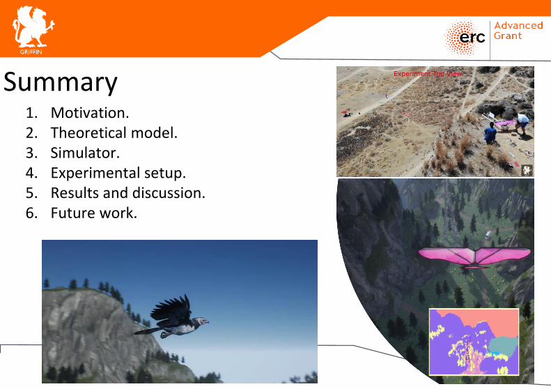
1. Motivation.2. Theoretical model.3. Simulator.4. Experimental setup.5. Results and discussion.6. Future work.
2
Summary
1. Motivation
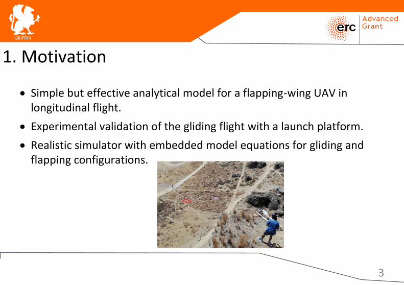
• Simple but effective analytical model for a flapping-wing UAV in longitudinal flight.
• Experimental validation of the gliding flight with a launch platform.
• Realistic simulator with embedded model equations for gliding and flapping configurations.
3
2. Theoretical model
• Simple linearized model for gliding and flapping based on linearized potential theory.
• Previous work:• R. Fernandez-Feria et al. (2016 and 2017)[1][2]• A. Martín-Alcántara et al. (2019).
• Suitable for high Reynolds numbers, low flapping amplitudes and moderate frequencies.
• Non-dimensional model: Easily extendable to other designs.
4[1] https://doi.org/10.1017/jfm.2017.500[2] https://doi.org/10.1103/PhysRevFluids.1.084502
2. Theoretical model: Parameters and equations
5
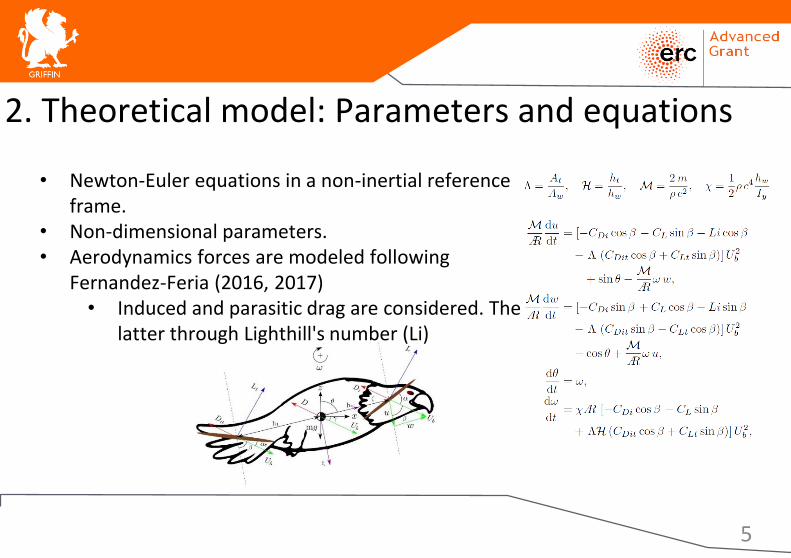
• Newton-Euler equations in a non-inertial reference frame.
• Non-dimensional parameters.• Aerodynamics forces are modeled following
Fernandez-Feria (2016, 2017)• Induced and parasitic drag are considered. The
latter through Lighthill's number (Li)

3. Simulator: Framework
• Integrated in the UE4 Airsim framework.• Fast calculation of dynamic equations:
Gliding, flapping and transitions.• Modular framework:
• Realistic render engine.• Sensor model provides camera,
barometer, IMU, GPS, Magnetometer, distance sensor and lidar.
• Environment model.• Physics engine.
6
3. Simulator: Performance
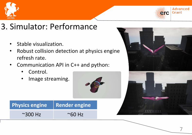
• Stable visualization.• Robust collision detection at physics engine
refresh rate.• Communication API in C++ and python:
• Control.• Image streaming.
Physics engine Render engine
~300 Hz ~60 Hz
7
4. Experimental Setup: Platform
8
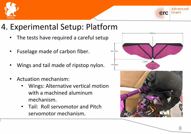
• The tests have required a careful setup
• Fuselage made of carbon fiber.
• Wings and tail made of ripstop nylon.
• Actuation mechanism:• Wings: Alternative vertical motion
with a machined aluminum mechanism.
• Tail: Roll servomotor and Pitch servomotor mechanism.
4. Experimental Setup: Hardware specifications
9
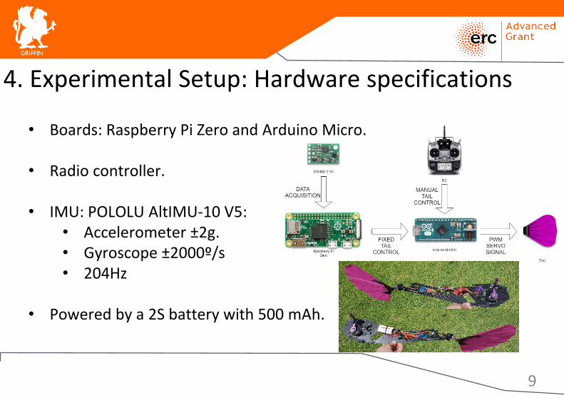
• Boards: Raspberry Pi Zero and Arduino Micro.
• Radio controller.
• IMU: POLOLU AltIMU-10 V5:• Accelerometer ±2g.• Gyroscope ±2000º/s• 204Hz
• Powered by a 2S battery with 500 mAh.
4. Experimental Setup: Launcher platform
10
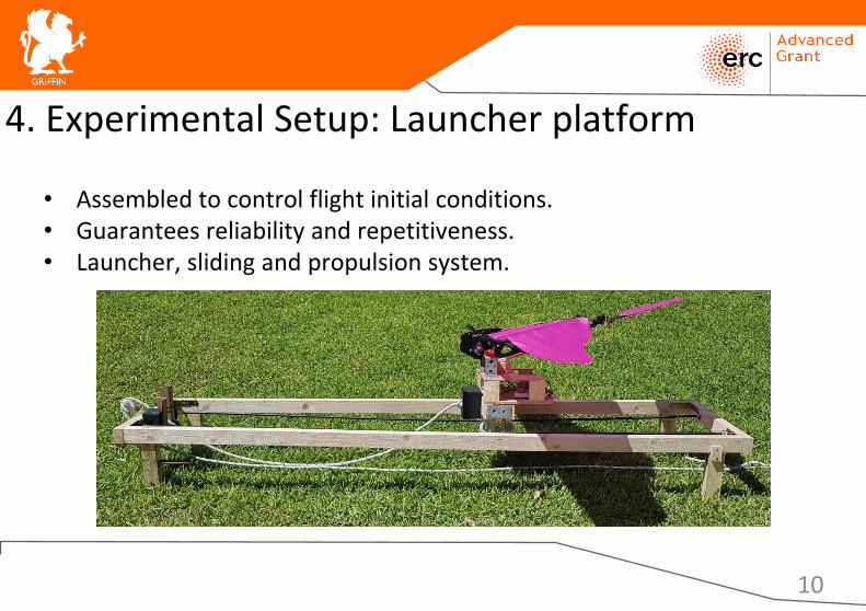
• Assembled to control flight initial conditions.• Guarantees reliability and repetitiveness.• Launcher, sliding and propulsion system.
4. Experimental Setup: Scenario
11
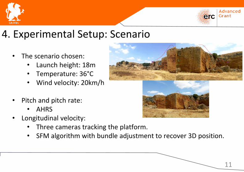
• The scenario chosen: • Launch height: 18m• Temperature: 36°C• Wind velocity: 20km/h
• Pitch and pitch rate: • AHRS
• Longitudinal velocity:• Three cameras tracking the platform. • SFM algorithm with bundle adjustment to recover 3D position.
5. Results and discussion: Experiments
12
5. Results and discussion: Experiments
13
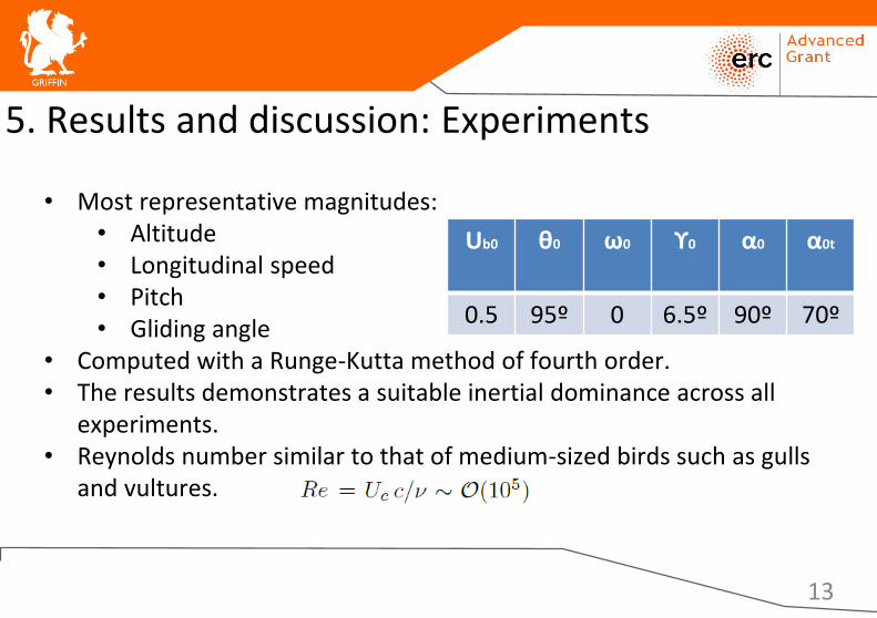
• Most representative magnitudes:• Altitude• Longitudinal speed• Pitch• Gliding angle
• Computed with a Runge-Kutta method of fourth order.• The results demonstrates a suitable inertial dominance across all
experiments.• Reynolds number similar to that of medium-sized birds such as gulls
and vultures.
Ub0 θ0 ω0 ϒ0 α0 α0t
0.5 95º 0 6.5º 90º 70º
5. Results and discussion: Comparison
14
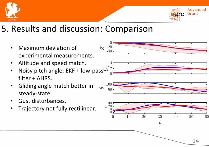
• Maximum deviation of experimental measurements.
• Altitude and speed match.• Noisy pitch angle: EKF + low-pass
filter + AHRS.• Gliding angle match better in
steady-state.• Gust disturbances.• Trajectory not fully rectilinear.

6. Conclusions and future work
• Simple model to understand theaerodynamic behavior
• Crucial launcher platform• Novel simulator incorporating
model equations
• Experimental validation of flapping-wing flight episodes
• Multiple ornithopters cooperation• High autonomy. Surveillance and
rescue task
15

Thanks for your attention
16
Related Documents