Behavior Research Methods, Instruments, & Computers 2002, 34 (4), 561-572 Quantitative eye movement measurements can provide invaluable information for the diagnosis and study of var- ious neurological disorders and are an essential tool in fun- damental research on the oculomotor system (Leigh & Zee, 1999). Human eye movements can be broken down into three distinct axes of rotation: horizontal, vertical, and torsional. Although horizontal and vertical eye movements are true rotations around the center of the eye, these can be usefully described as translational, albeit with units of angular measure. The primary function of these movements is to bring and keep the center of images of interest on the eye’s fovea. Eye movements can have velocities up to 600º/sec (Leigh & Zee, 1999) and power spectral components up to 50 Hz (spectral analysis of own data). Eye movements often contain both translational and torsional components. Some torsional abnormalities, such as pathological torsion pulsion (Anderson & MacAskill, 1998), may be present only during translational eye movement. A number of methods have been proposed or used for measuring eye movements, each with different features and levels of performance. Of particular importance is whether eye movements need to be measured only in one dimension (e.g., horizontal), in two dimensions (horizon- tal and vertical), or in three dimensions (translational plus torsional). The target goal of our laser-based eye tracker is to track eye movements in three dimensions. A summary of the most common methods for measuring three-dimensional (3-D) eye movements follows. Several methods are based on tracking contact lenses. The performance of these systems is typically very good, but all are invasive, uncomfortable, and often require a topical anaesthetic. Matin and Pearce (1964) developed a scleral contact lens system that uses a pair of noncoplanar 4-mm-diameter mirrors embedded in the surface of the lens on opposite sides of the pupil. Their system has a res- olution of 0.00028º within a range of 610º for all three di- mensions and has a flat frequency response up to 1.3 kHz. Robinson (1963) used a pair of magnetic search coils placed around the head to induce an electrical current into a pair of orthogonal magnetic coils placed in a scleral contact lens. Translational eye movements could be measured down to 0.25º over a 620º range and torsional movements could be resolved down to 0.0042º. Their system had a band- width of 1.0 kHz. Methods based on tracking the retina (Young & Sheena, 1975) and the fundus (Kawai, Tamura, Kani, & Kariya, 1986) have been developed that can achieve bandwidths up to 60 Hz (Mulligan, 1997), although most fail to exceed 5 Hz. Photographic images have also been used to measure eye movements, but the long postprocessing time required to develop and analyze the photographs severely limits this approach. In the last 5 years or so, video-based systems have taken on a prominence in the eye-tracking world. The advent of digital recording devices (CCD and CMOS cameras) has led to video-based systems’ becoming smaller, more reli- able, and substantially faster than earlier analogue recording devices. An example is Alphabio’s “Eyeputer” (http://www. electronica.fr/alphabio), which can sample at up to 480 Hz 561 Copyright 2002 Psychonomic Society, Inc. The laser-based eye tracker described in this paper is not available as a commercial product, but consideration is being given to pursuing this possibility pending the outcome of further development work. K.I., R.D.J., P.J.B., and T.J.A. are members of the Christchurch Movement Disorders and Brain Research Group. Correspondence concerning this article should be addressed to K. Irie, Lincoln Technology, P. O. Box 133, Lincoln, Christchurch 8152, New Zealand (e-mail: iriek@lincoln. ac.nz). A laser-based eye-tracking system KENJI IRIE, BRUCE A. WILSON, and RICHARD D. JONES University of Canterbury, Christchurch, New Zealand and Christchurch Hospital, Christchurch, New Zealand PHILIP J. BONES University of Canterbury, Christchurch, New Zealand and TIM J. ANDERSON Christchurch Hospital, Christchurch, New Zealand This paper reports on the development of a new eye-tracking system for noninvasive recording of eye movements. The eye tracker uses a flying-spot laser to selectively image landmarks on the eye and, sub- sequently, measure horizontal, vertical, and torsional eye movements. Considerable work was required to overcome the adverse effects of specular reflection of the flying-spot from the surface of the eye onto the sensing elements of the eye tracker. These effects have been largely overcome, and the eye-tracker has been used to document eye movement abnormalities, such as abnormal torsional pulsion of sac- cades, in the clinical setting.

Welcome message from author
This document is posted to help you gain knowledge. Please leave a comment to let me know what you think about it! Share it to your friends and learn new things together.
Transcript

Behavior Research Methods Instruments amp Computers2002 34 (4) 561-572
Quantitative eye movement measurements can provideinvaluable information for the diagnosis and study of var-ious neurological disorders and are an essential tool in fun-damental research on the oculomotor system (Leigh ampZee 1999)
Human eye movements can be broken down into threedistinct axes of rotation horizontal vertical and torsionalAlthough horizontal and vertical eye movements are truerotations around the center of the eye these can be usefullydescribed as translational albeit with units of angularmeasure The primary function of these movements is tobring and keep the center of images of interest on the eyersquosfovea Eye movements can have velocities up to 600ordmsec(Leigh amp Zee 1999) and power spectral components up to50 Hz (spectral analysis of own data) Eye movementsoften contain both translational and torsional componentsSome torsional abnormalities such as pathological torsionpulsion (Anderson amp MacAskill 1998) may be presentonly during translational eye movement
A number of methods have been proposed or used formeasuring eye movements each with different featuresand levels of performance Of particular importance iswhether eye movements need to be measured only in onedimension (eg horizontal) in two dimensions (horizon-tal and vertical) or in three dimensions (translational plustorsional) The target goal of our laser-based eye tracker is
to track eye movements in three dimensions A summary ofthe most common methods for measuring three-dimensional(3-D) eye movements follows
Several methods are based on tracking contact lensesThe performance of these systems is typically very goodbut all are invasive uncomfortable and often require atopical anaesthetic Matin and Pearce (1964) developed ascleral contact lens system that uses a pair of noncoplanar4-mm-diameter mirrors embedded in the surface of thelens on opposite sides of the pupil Their system has a res-olution of 000028ordm within a range of 610ordm for all three di-mensions and has a flat frequency response up to 13 kHzRobinson (1963) used a pair of magnetic search coils placedaround the head to induce an electrical current into a pairof orthogonal magnetic coils placed in a scleral contactlens Translational eye movements could be measureddown to 025ordm over a 620ordm range and torsional movementscould be resolved down to 00042ordm Their system had a band-width of 10 kHz
Methods based on tracking the retina (Young amp Sheena1975) and the fundus (Kawai Tamura Kani amp Kariya 1986)have been developed that can achieve bandwidths up to60 Hz (Mulligan 1997) although most fail to exceed 5 HzPhotographic images have also been used to measure eyemovements but the long postprocessing time required todevelop and analyze the photographs severely limits thisapproach
In the last 5 years or so video-based systems have takenon a prominence in the eye-tracking world The advent ofdigital recording devices (CCD and CMOS cameras) hasled to video-based systemsrsquo becoming smaller more reli-able and substantially faster than earlier analogue recordingdevices An example is Alphabiorsquos ldquoEyeputerrdquo (httpwwwelectronicafralphabio) which can sample at up to 480 Hz
561 Copyright 2002 Psychonomic Society Inc
The laser-based eye tracker described in this paper is not available asa commercial product but consideration is being given to pursuing thispossibility pending the outcome of further development work KIRDJ PJB and TJA are members of the Christchurch MovementDisorders and Brain Research Group Correspondence concerning thisarticle should be addressed to K Irie Lincoln Technology P O Box 133Lincoln Christchurch 8152 New Zealand (e-mail irieklincoln acnz)
A laser-based eye-tracking system
KENJI IRIE BRUCE A WILSON and RICHARD D JONESUniversity of Canterbury Christchurch New Zealand
and Christchurch Hospital Christchurch New Zealand
PHILIP J BONESUniversity of Canterbury Christchurch New Zealand
and
TIM J ANDERSONChristchurch Hospital Christchurch New Zealand
This paper reports on the development of a new eye-tracking system for noninvasive recording of eyemovements The eye tracker uses a flying-spot laser to selectively image landmarks on the eye and sub-sequently measure horizontal vertical and torsional eye movements Considerable work was requiredto overcome the adverse effects of specular reflection of the flying-spot from the surface of the eye ontothe sensing elements of the eye tracker These effects have been largely overcome and the eye-trackerhas been used to document eye movement abnormalities such as abnormal torsional pulsion of sac-cades in the clinical setting
562 IRIE WILSON JONES BONES AND ANDERSON
with a horizontal range of 630ordm vertical range of 620ordmand a torsional range of 645ordm It has a precision of 603ordmtranslationally and 602ordm torsionally at this sample ratealthough the horizontal and vertical precision can be im-proved to 601ordm by reducing the sample rate to 60 HzOther manufacturers of camera-based systems includeApplied Science Laboratories (httpwww a-s-lcom)SKALAR Medical BV (httpwwwwirehub nl~skalar)SensorMotoric Instruments (httpwww smide) andChronos Vision GmbH (Clarke Ditterich Druumlen Schoumln-feld amp Steineke 2002)
Prior to the development of high frame rate video-basedeye trackers it was not possible to measure high-bandwidthsaccadic eye movements in three dimensions by noninva-sive measures Consequently in 1994 we commenced de-velopment of a high-speed 3-D laser-based flying-spoteye-tracking system (Jones Wilson amp Bones 1996 Wil-son Anderson Preddie Jones amp Bones 1996a 1996bWilson Jones amp Bones 1995) By partially imaging theeye with a low-power eye-safe laser it was recognized thatit would be possible to achieve high-speed high-bandwidthnoninvasive 3-D eye tracking with only a fraction of thedata processing that would be required for processing fullvideo images of the eye The spatial resolution is limitedonly by the laser spot size and the sampling frequency ofthe sensing system The resolution in time is limited onlyby the speed of the sensors detecting the backscatteredlight the bandwidth of the mechanical deflection appara-tus and the real-time computing capacity This paper de-scribes our laser-based eye-tracking system and in par-ticular outlines some of the major obstacles met along theway and how they have been overcome to achieve a sys-tem with a performance suitable for both clinical and re-search applications As far as the authors are aware this isthe first eye tracker to use a laser for tracking 3-D eyemovements
SYSTEM DESCRIPTION
System OverviewThe eye tracker is essentially a specialized flying-spot
scanner and consists of four main subsystems1 A 650-nm wavelength 1-mW red laser (attenuated to
015 mW) focused to produce an illumination spot of 53 mmon the eye (complying with Australian Standard AS2211[1991] for laser safety Eckert 1996)
2 Mirrors that steer the small spot of illuminationacross the eye The beam-steering system consists of two galvanometer-driven beam-steering mirrors servo con-trollers and a digital-to-analogue converter The mirrorsare located above the subjectrsquos eye
3 A receiver that measures the reflected light from theeye consisting of two sampling channels each with twophotodiode sensors The signals from the photodiodes arepassed through a transimpedance amplifier and a variable-gain amplifier before being digitized by an analogue-to-digital converter card on a PC running MS-DOS
4 A computer that controls the scanner stores andprocesses data and interacts with the user The eye trackersoftware tracks the pupil in real time and directs the beam-steering mirrors to keep a laser scan pattern centered onthe pupil The system currently operates at 169 scans persecond The torsional movements are too computationallyexpensive to perform in real time on the current hardwareand are calculated off line
A block diagram of the eye tracker is shown in Figure 1The headset of the eye tracker can be seen modeled in Fig-ure 2
Scan cycle The scan cycle is a series of sweeps to par-tially image the eye so that the eyersquos translational and tor-sional position can be determined The eye tracker deter-mines the position of the eye on the basis of a horizontalsweep a vertical sweep and a circular sweep In addition
Figure 1 Block diagram of the eye tracker system
Eye-safe Laser
Half SilveredMirror
PhotodiodeArray (x4)
Eye
x-axis Scanner
y-axis Scanner
Gain
Amplifiers
MirrorServo Drivers
AntialiasingFilter
DAConverter
ScannerTrajectories
Interrupt
Sync
Trigger
ADConverter
ImageData
Eye TrackerSoftware
Pentium-Based PC
UserInterface
Eye MovementData
HardDisk
A LASER-BASED EYE-TRACKING SYSTEM 563
to these three sweeps there is a fly-back period betweensweeps to position the spot ready for the next scan Thereare therefore six operations or phases that make up eachcycle of measurement Each sweep over the iris and pupilprovides an image of the reflectivity of the eye along aline Figure 3 shows the trajectory of the laser spot throughthese six phases of the scan cycle Phase 1 moves the beamto the start point of the vertical sweep whereas Phase 2 isthe vertical sweep across the iris and pupil From this ver-
tical sweep the edges of the pupil are found and thus thevertical center of the pupil can be located The setup forthe circular sweep is performed in Phase 3 and Phase 4records the iris pattern over a 270ordm arc Torsion of the eyeis determined by cross-correlation of consecutive circularsweeps Phase 5 moves the beam to the start point for thehorizontal sweep whereas Phase 6 is the horizontal sweepacross the iris and pupil From this horizontal sweep theedges of the pupil are found and thus the horizontal cen-ter of the pupil can be located
The size of the pupil can change over the course of themeasurement period but abnormal pupillary shape (egovoid) may result in small inaccuracies in estimation oftranslational and torsional positions Rare defects of theiris such as aniridia (congenital absence of iris) precludemeasurement of torsional movements
At the start of an eye movement recording session thescan pattern is placed approximately over the subjectrsquospupiliris The eye tracker is then allowed to ldquolock onrdquo tothe subjectrsquos pupil (and a position calibration performed)before eye movements are recorded If the edges of thepupil are not detected in both the horizontal and the verti-cal sweeps over several consecutive scans the eye trackerenters a search mode and actively seeks the pupil until itldquolocks onrdquo to the subjectrsquos pupil again
Data processing The eye tracker software controls thecollection processing and storage of scan informationThe eye tracker software tracks the pupil in real time anddirects the beam-steering mirrors to keep the scan patterncentered on the pupil A typical example of a horizontal(or a vertical) sweep of the eye is shown in Figure 4 Thepupil is indicated by the low-level signal area in the cen-ter of the sweep The iris is seen as the higher level signaleither side of the pupil region and the edges of the pupilcan be seen as the sharp signal steps in between the irisand the pupil The center position of the pupil can be de-
Figure 2 Front view of the eye tracker headset
Figure 3 The six phases of a scan cycle
564 IRIE WILSON JONES BONES AND ANDERSON
termined from the top bottom left and right edges of thehorizontal and vertical sweeps
The entire torsion estimation process is based on imag-ing features on the iris The features are primarily com-posed of radial striations By recording images of the iristorsional eye movements can be estimated by correlatingsubsequent images with each other Although this is a rel-atively straightforward process it is too computationallyexpensive to be undertaken in real time on the currenthardware Instead the scans are written to hard disk andthe circular sweeps are correlated off line to estimate tor-sional eye movements
OBSTACLES
Specular Reflections on Translational TrackingParamount in achieving a clinically useful performance
from the eye tracker is achieving reliable and accurate
tracking of the pupil Both translational and torsionalmeasurements are affected by the quality of the pupiltracking Initially the eye tracker performed erraticallyowing to its being unable to reliably track translational eyemovements Specular reflections were determined to be amajor cause of tracking error as a result of the laser beamrsquosreasonably frequently reflecting directly off the eye sur-face onto one or more of the four sensors Figure 5 illus-trates the specular reflection process The sensors hadbeen chosen and positioned so as to best detect the back-scattered light from the eye but became saturated when themuch higher intensity specular reflection passed ontothem Two levels of specular reflection were identifiedsaturating specular reflection which saturated the photodi-ode output from an entire sweep and occurred when the laserbeam reflected onto one of the photodiodes for 1ndash2 msecand nonsaturating specular reflection which affected onlythe part of the sweep that the specular reflection occurredupon An example of saturating specular reflections upona horizontal sweep is shown in Figure 6 Figure 6A has astrong specular reflection occurring over the left boundarybetween the pupil and the iris This biases the pupil edgedetection algorithm which will inaccurately determinethe pupil position Figure 6B has two strong specular re-flections apparent through the horizontal sweep occurringnear the edges between the pupil and the iris This also bi-ases the pupil edge-detection algorithm The result of thesestrong specular reflections is gross oscillation or loss ofpupil tracking
A two-part solution was implemented to reduce the er-roneous eye tracking caused by specular reflection Firstthe four sensors were placed around the eye to utilize thedual-channel sampling capability of the eye tracker sys-tem so as to ensure that at least one sampling channel isfree from specular reflections at all times With the sen-sors positioned around the eye as shown in Figure 7 a hor-izontal sweep can saturate only one of the sensor pairs at
Figure 4 A typical horizontal sweep recording from the eyetracker
IncidentLaser Beam
SpecularReflection
Sensor
Back-scatteredlight
IncidentLaser Beam
SpecularReflection
Sensor
Back-scatteredlight
A B
Figure 5 Diagram demonstrating (A) how specular reflection occurs and (B) how certain angles of incidence cause specular re-flection to directly impose on a sensor
A LASER-BASED EYE-TRACKING SYSTEM 565
any given time since the projected specular reflection is aslightly curved horizontal line Similarly during a verticalsweep only one sensor (and therefore one sampling chan-nel) can be saturated at any given time since the projectedspecular reflection is a slightly curved vertical line
The second part of the solution was to minimize the ef-fect of any remaining specular reflections By utilizing thedual-channel sampling capability of the eye tracker manyof the unwanted effects of saturating specular reflectionswere overcome by developing an algorithm capable of de-tecting and removing data contaminated by saturatingspecular reflections
Figure 8 shows the major components of the samplingand channel selection subsystem of the eye tracker imple-mented to minimize the influence of any remaining satu-rating specular reflections The optics have been carefullypositioned so as to ensure that at least one of the samplingchannels is free from specular reflection during any sweepData from the sensor pairs are summed in hardware on theeye tracker headset and are sampled by the A D converterboard in the eye tracker PC The channel selection algo-rithm is passed data from the two sampling channels Thetwo data streams (each 8-bit resolution) are checked forany saturation (ie signal levels of 255) and there arefour possible resulting cases Both channels are free of sat-urations Channel 1 contains saturations whereas Channel2 does not Channel 2 contains saturations whereas Chan-nel 1 does not and both channels contain saturations Todetermine the position of the center of the pupil the algo-rithm selects the channel with no saturation and the widestpupil width detected
Distortions Affecting Torsional TrackingThe flying-spot approach to measuring eye movements
inherently brings several types of distortion into the tor-sional image All image-based systems are susceptible tospecular reflections from the eye that may render part of
the torsional image unusable A scanning eye position track-ing system (as opposed to an absolute eye position mea-surement system such as some contact lens systems andthe video-based systems) suffers from additional time de-lays in the tracking feedback These time delays can distortthe recorded data and reduce the accuracy and reliabilityof the torsional eye tracking Geometric distortions canalso occur because of the spherical imaging of the surfaceof the eye Each of these distortions although indepen-dent of each other may occur at the same time Also in-herent in the eye tracker sampling process is an intensitygradient (brightness variation) along the recorded imagethat is dependent on the sensor positions relative to thescan pattern position This implies that not only do the ef-fects of the distortions need to be reduced but also therecorded data need to be filtered to remove the intensitygradients which can severely bias the cross-correlationalgorithm
The most destructive distortion by far is the specular re-flections Specular reflections are additive and image datacorrupted by saturating specular reflections from the sur-
Figure 6 Horizontal sweep recordings from the eye tracker on the translational eye movement simulator show-ing saturating specular reflections (A) a specular reflection occurring during a scan of the pupil and (B) two spec-ular reflections one on the pupiliris boundary and one on the iris
Figure 7 A set of sensor positions with a good balance betweenspecular reflection minimization and signal levels The sensorsare placed 1ndash2 cm in front of the subjectrsquos eye
566 IRIE WILSON JONES BONES AND ANDERSON
face of the eye cannot be recovered However they se-verely bias the cross-correlation algorithm and need to beremoved Shown below in Figure 10A is a torsional record-ing saturated by specular reflection (further specular re-flection in a torsional recording can be seen below in Fig-ure 12A) As the cross-correlation function multiplies thetwo signals to be correlated the removal of the effect ofthe saturating specular reflection can be achieved by set-ting areas of saturating specular reflection to zero This isachieved by multiplying the original signal with a masksignal consisting of 1s where nonsaturated data are presentand 0s where saturation occurs Saturations are detected assignals equal to the limit of the 8-bit AD output (integervalue 255) The setting of values within signals to 0 canbias the cross-correlation function The result of the cross-correlation needs careful unbiasing to ensure that the re-moval of saturating specular reflections does not dominatethe cross-correlation
In order to better illustrate this a series of cross-correlations is shown in Figure 9 Figure 9A shows thecross-correlation of series of two rectangular signals Theresult of the cross-correlation is a triangular shaped signalThis represents the bias inherent in noncircular correla-tions The result from the cross-correlation should be ahorizontal line with no peak signifying that the two inputrectangular signals are equal across their entirety The
right-hand diagram of Figure 9A is the triangular shapedcross-correlation result divided by itself Dividing the re-sults of cross-correlations by this reference weighting sig-nal unbiases the cross-correlation
Figure 9B shows the same cross-correlation process asin Figure 9 but with two strong features added to the orig-inal input signals The result of the cross-correlation is aslightly wavy triangular shape The result is then dividedby the reference weighting signal and the cross-correlationshown on the right of Figure 9B The peak of the result isin the very center of the signal showing that the two inputsignals have the highest correlation when they coincide
An example of the problem of setting values within theinput signals to 0 is shown in Figure 9C Ten samples onthe right-hand side of one of the input signals have beenarbitrarily set to 0 to simulate the removal of a saturatingspecular reflection The resulting biased and unbiasedcross-correlations are distorted and the peak that shouldbe located in the center of unbiased cross-correlation isreduced and no longer the maximum point of the cross-correlation
The cause of the distortion is due to the 0-values intro-duced into the signal One solution that would improve theresult of the cross-correlation is to change the referenceweighting signal to incorporate the effect of adding 0-values to the signals The reference weighting is formed
Sensor Pair 1
Sensor Pair 2
Pupil Edges
Pupil Edges
0
Test forchannel
saturation
Optics with minimaloccurrence of specularreflection ensuring atleast one channelremains uncorruptedby specular reflectionswhen the scan pattern iscentered on the pupil
Dual-channel sampling withhardware summers
Channel selection for specular reflection free data(chooses neither channel if both channels containspecular reflection saturations)
Figure 8 The dual-channel sampling and channel selection eye tracker subsystem
A LASER-BASED EYE-TRACKING SYSTEM 567
by the cross-correlation of two signals sampled at Level 1each being the same length as the input signals A modi-fication to the input signals of the reference weightingcross-correlation can be made to incorporate the areas ofthe signals being unbiased that have been set to 0 Fig-ure 9D illustrates the production of a new weighting sig-nal with one of the input signals having 0-values in thesame place as the signal being unbiased The resultingweighting signal is triangular in shape with ridges Whenthe result of the biased cross-correlation in Figure 9C isdivided by the new weighting signal the result is a muchmore pronounced center peak as shown in Figure 9Ewhich is once again the maximum point of the cross-correlation
The process of removing saturating specular reflectionsgives a substantial improvement in the torsional resultsWithout this process torsional estimation would tend to fol-low the paths of specular reflection that are almost alwaysseen in torsional images
Intensity gradients in torsional signals can bias thecross-correlation process and produce erroneous resultsThe gradients occur because the sensor coverage of theeye is uneven meaning that average light levels through-out the recorded data can vary However the gradients arelow frequency in nature and can be removed with a high-pass filter (a 32-tap Hamming filter with a normalizedcutoff frequency of 015 fS where fS is the sampling fre-quency was used) Its performance was however severely
Figure 9 A series of diagrams illustrating the use of weightings to unbias noncircularcross-correlation results (A) generation of a reference weighting that can be used to unbiasother noncircular cross-correlations of the same length and same overall signal level (B) Twosignals that when unbiased by the reference weighting shown in panel A have a peak in thecenter of the cross-correlation result meaning that the signals are best correlated when thereis no offset between the two signals (C) The addition of 0-values within one of the input sig-nals to simulate specular reflection removal alters the cross-correlation result unbiased withthe reference weighting shown in panel A (D) The generation of a new weighting to unbiasthe cross-correlation shown in panel C (E) The cross-correlation of the signals shown inpanel C with the new weighting signal unbiasing the result The peak of the unbiased signalis now back in the center of the result meaning that the signals are best correlated whenthere is no offset between them
568 IRIE WILSON JONES BONES AND ANDERSON
affected by the boundary effects generated by specular re-flections or removal of specular reflection by setting val-ues to zero Prior to filtering saturating specular reflectionis cut out and replaced with data linearly interpolated fromthe points either side of the areas of specular reflectionThe linear interpolation maintains continuity and there-fore reduces the boundary effects of discontinuous datawhen the signal is filtered Figure 10 illustrates the filter-ing process used to remove intensity gradients from eyetracker torsional data
EYE-TRACKER PERFORMANCE
The performance of the laser-based eye tracker has beenmeasured both on artificial eye movement simulators andwith human subjects
Eye Movement SimulatorsThe eye trackerrsquos performance in both translational and
torsional tracking has been quantified using two prototypeartificial eye movement simulators able to provide repeat-able and controllable eye movements The first simulatorgenerated translational movements over a 25ordm (radial)range and was capable of oscillating the eye at 10 Hz It con-sisted of a prosthetic eye with high-speed servomotors
controlling the horizontal and vertical eye movements asis shown in Figure 11
The second simulator generated high-speed transla-tional and torsional movements and was constructed of arotating plate with a positionable prosthetic iris and pupilThe simulator was capable of 47-Hz horizontal verticaland torsional movements The simulators were used to de-termine the eye trackers maximum eye tracking velocitybandwidth resolution noise and range The eye trackerwas able to track translational movements of up to 660ordmat velocities of 900ordmsec and torsional movements of up to688ordm at velocities of 850ordmsec The performance charac-teristics of the eye tracker are shown in Table 1
The torsion estimation algorithm is reliant upon accu-rate positioning of the torsional sweep when recording theiris pattern During translational eye movement the scanpattern tracks the pupil as it moves but the positioning ofthe torsional sweep becomes progressively offset as trans-lational velocity increases This affects the torsion estima-tion cross-correlation algorithm and results in an offset inthe torsion estimation With the current scan rate of 169 scansper second (the maximum rate of real-time computationwith the current Pentium 100 PC) torsion estimation isaccurate for translational eye movements of less than70ordmsec This could be improved by rearranging the eye
Figure 10 Diagrams illustrating the filtering process to remove intensity gradients on the tor-sional recordings (A) Raw torsional recording including two specular reflections (B) The torsionalrecording with linear interpolation over areas of specular reflection (C) The signal shown in panelB filtered with a 32-tap Hamming filter ( v 5 015) (D) The filtered signal with the original areasof specular reflection set to 0
A LASER-BASED EYE-TRACKING SYSTEM 569
track scan pattern so that the torsional sweep is performedfirst (to minimize the time for eye movement between thepupil position detection and the torsional sweep) or by in-creasing the scan rate by increasing computing power Therecording is from the translational eye movement simula-tor performing 50ordm saccades at a velocity of approximately140ordmsec
Normal SubjectsEight normal subjects were tested to evaluate the eye
trackerrsquos tracking ability range and noise The test groupconsisted of 4 females and 4 males with an average ageof 30 years (range 18ndash60 years) and a wide range of eyecolors A flat board 12 m square containing a set of eightfixed viewing points (positioned 20ordm from central fixa-
tion) was used to guide the subjectsrsquo eyes in different pat-terns of up to 620ordm to generate translational movementsThe subjects tilted their heads from side to side (ie rota-tion of the head about the naso-occipital axis) to generatetorsional ocular counter-roll Data without large glitchesor loss of tracking was obtained from 5 subjects when eyemovements were limited to 614ordm horizontally and 614ordmvertically (in 2 of these 5 subjects 625ordm horizontally andvertically were achieved) Translational performance lim-itations arise from obstruction of the laser beam by eyelidsand eyelashes and hence varied from person to personEnhancements to the mirrorsensor part of the systemshould be able to improve the range of eye movements forthe majority of subjects Figure 12 shows a torsionalrecording of ocular counter-roll from a normal subject
Table 1Performance Summary of the Eye Tracker
Translational PerformanceTracking speed 900ordmsec (3-mm pupil diameter)Range (simulators) 660ordm radiusRange (humans) at least 614ordm horizontalvertical (20ordm oblique)Resolution 017ordm of arc (limit of 8-bit sampling resolution)Bandwidth (3 dB) horizontal 47 Hz
vertical 30 HzNoise (stationary simulators) horizontal 013ordm RMS (8cent of arc)
vertical 012ordm RMS (7cent of arc)Noise (humans focusing horizontal 012ordm RMS (7cent of arc)on stationary point object) vertical 013ordm RMS (8cent of arc)
Torsional PerformanceTracking speed 850ordmsecRange minimum 630ordm tested on simulators on movements up to 88ordmResolution 105ordm without interpolationBandwidth unable to test with current simulators expected to match or better the
translational bandwidth (47 Hz) posttorsional filter cutoff set to 40 Hz forremoval of high-frequency noise
Noise 04ordm RMSReliability torsion estimation valid for translation velocities 70ordmsec Tracking offsets at this
speed can generate a maximum false torsion equal to the torsional noise levelof 04ordm which increases with higher speeds geometrical offsets can causefalse torsion up to 5ordm at a gaze direction of 20ordm from center
Figure 11 Block diagram of the translational eye movement simulator
ManualY-input
SignalGenerator
Y-input
SignalGeneratorX-input
ManualX-input
Y-input
X-input
y-axis ServoPosition
x-axis ServoPosition
Microchip 16C71Microcontroller
y-axis Servo Motor
x-axis Servo Motor
Artificial Eye
y-axisRotation
x-axisRotation
570 IRIE WILSON JONES BONES AND ANDERSON
vigorously tilting his head from side to side (approxi-mately 35 sec) The maximum torsional movements ob-served and recorded were 30ordm
Figures 13A and 13B show recordings of subjects per-forming saccades The fidelity of the high-frequency com-ponents of the saccades can be seen to be most acceptable
Poor test data (data containing large glitches) were ob-tained from 2 subjects owing to mechanical constraints(deep-set eyes nose shape and nose size) that preventedthe eye tracker optics (laser mirrors and sensors) frombeing centered optimally over the subjectrsquos pupil (transla-tional offsets of the optics from the center of the pupilwere equivalent to 37ordm and 14ordm) The tests were still per-formed but the results were noisy and often showed totalloss of tracking No useful data (owing to failure of track-ing) could be obtained from 1 of the subjects because ofthe very dark iris coloring (difficult to visually differenti-ate pupil from iris)
Clinical CasesEye movement recordings were recorded in a patient
who had suffered a recent cerebellar stroke Several patho-logical abnormalities were evident in both the horizontaland the vertical eye movement recordings (Figure 13B)including ocular dysmetria (overshooting when saccadic
movements were made) gaze-evoked horizontal nystag-mus and a high number of square-wave jerks The lattercan also be seen in normal subjects but occur much lessfrequently No abnormal torsional movements were ob-served
We have also used the device to record torsional pul-sion of saccades in patients with neurological disorders(Anderson amp MacAskill 1998)
CONCLUSION
A noninvasive laser-based eye tracker has been devel-oped that can measure high-speed eye movements in allthree axes of eye rotation On a set of 8 normal subjectsthe translational tracking was found to be reliable and ac-curate on 5 subjects over a range of at least 614ordm hori-zontally and vertically It is expected that the performanceof 2 of the remaining subjects would be at the same levelfollowing improvements to the eye tracker headset toallow for better positioning of the eye tracker optics on theeye Currently the eye tracker can record eye movementonly in one eye at a time and is unable to measure eyemovements in people with extremely dark or absent irises
Overall the eye tracker compares well with other non-invasive eye-tracking systems and provides an alternative
50
100
150
200
250
20
10
0
ndash10
ndash20
Sca
n sa
mpl
e nu
mbe
rTo
rsio
n es
timat
ion
(deg
rees
)
100
100
200
200
300
300
400
400
500
500
600
600
Scan number
Scan number0
0
A
B
Figure 12 Torsion estimation from a normal subject undergoing ocular counter-roll (vigorous head movement600 scans 5 35 sec of recording) Note the torsional nystagmus (fast and slow phases) during the primary tor-sional movements (A) Estimated torsion eye movement overlaid on top of raw torsional data (white data repre-sents areas of saturating specular reflection) (B) A larger view of the torsion estimation trace
A LASER-BASED EYE-TRACKING SYSTEM 571
Figure 13 Translational eye movement recordings from the eye tracker (A) Horizontal and verticaltraces from a normal subject performing oblique (diagonal) saccades (1100 scans 5 65 sec of recording)Note the mild disconjugacy of the eyes during horizontal saccades (B) Vertical and horizontal eye move-ments in a patient who had suffered a cerebellar stroke (1940 scans 5 115 sec of recording)
572 IRIE WILSON JONES BONES AND ANDERSON
novel method for noninvasive simultaneous measurementof translational and torsional eye movements
REFERENCES
Anderson T J amp MacAskill M R (1998) Pathological torsionalpulsion of saccades An observational study in seven patients NewZealand Medical Journal 111 480-481
Clarke A H Ditterich J Druumlen K Schoumlnfeld U ampSteineke C (2002) Using high frame rate CMOS sensors for three-dimensional eye tracking Behavior Research Methods Instrumentsamp Computers 34 549-560
Eckert R (1996) Laser scanning eye tracker (Tech Rep) ChristchurchNew Zealand University of Canterbury Department of Electrical andElectronic Engineering
Jones R D Wilson B A amp Bones P J (1996) A flying-spot laserscanner for tracking eye movements In Proceedings of the IEEE 8thAnnual International Conference of the Engineering in Medicine andBiology Society (pp146-147) Los Alamitos CA IEEE ComputerSociety Press
Kawai H Tamura S Kani K amp Kariya K (1986) Eye movementanalysis system using fundus images Pattern Recognition 19 77-84
Leigh R J amp Zee D S (1999) The neurology of eye movements (3rded) New York Oxford University Press
Matin L amp Pearce D (1964) Three dimensional recording of rota-
tional eye movements by a new contact lens technique Biomedical ampScientific Instrumentation 2 79-95
Mulligan J B (1997) Image processing for improved eye-trackingaccuracy Behavior Research Methods Instruments amp Computers29 54-65
Robinson B (1963) A method of measuring eye movement using ascleral search coil in a magnetic field IEEE Transactions on Biomed-ical Engineering 10 137-145
Wilson B A Anderson T Preddie J Jones R D amp Bones P J(1996a) A flying spot laser scanner capable of measuring torsional eye-movements [Abstract] Journal of Vestibular Research 6 (Suppl)S75
Wilson B A Anderson T Preddie J Jones R D amp Bones P J(1996b) A flying spot laser scanner capable of measuring torsional eye-movements [Abstract] Neuro-Opthalmology 16 (Suppl) 177
Wilson B A Jones R D amp Bones P J (1995) A flying spot laserscanner for tracking eye-movements [Abstract] New Zealand Med-ical Journal 108 487
Young L R amp Sheena D (1975) Survey of eye movement record-ing methods Behavior Research Methods amp Instrumentation 7 397-429
(Manuscript received March 25 2002revision accepted for publication October 14 2002)
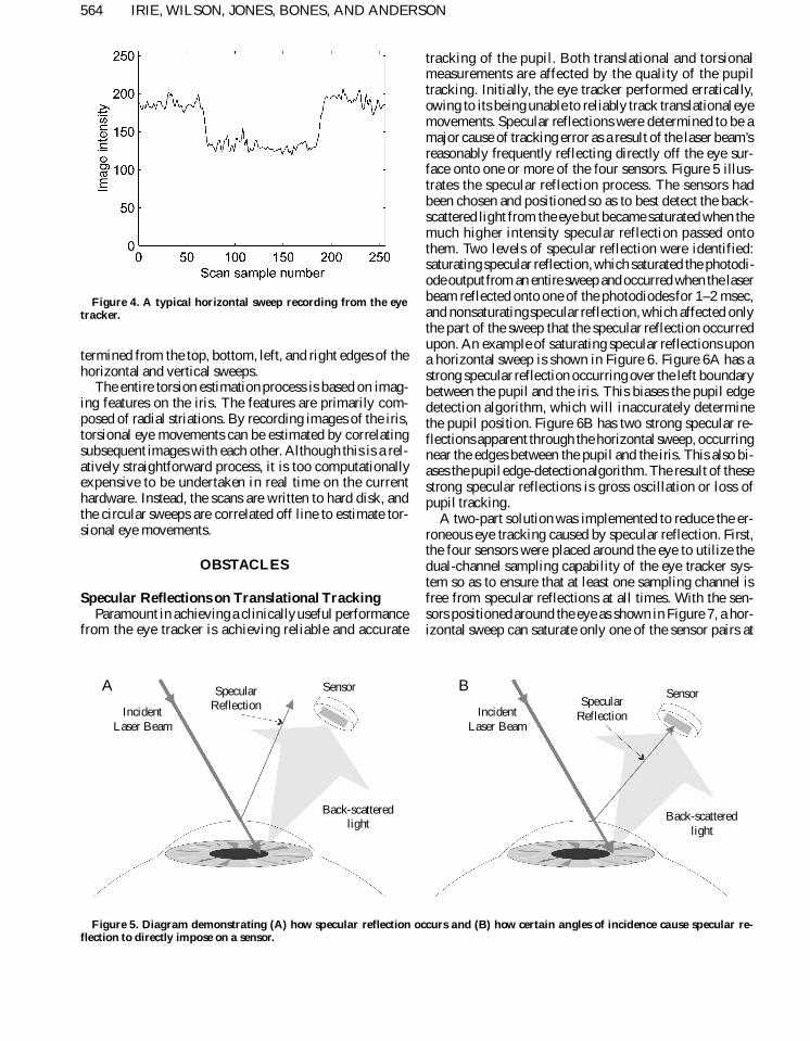
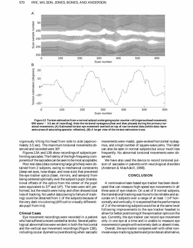
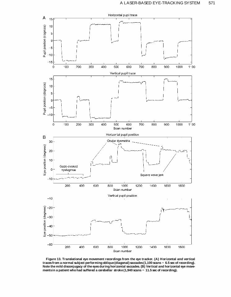
Related Documents