A KYOCERA GROUP COMPANY ELCO Varicon ™ Input/Output Rack and Panel Connectors

Welcome message from author
This document is posted to help you gain knowledge. Please leave a comment to let me know what you think about it! Share it to your friends and learn new things together.
Transcript

A KYOCERA GROUP COMPANY
ELCOVaricon™ Input/OutputRack and Panel Connectors
1ELCOELCO
Varicon®
Contents
The Varicon Range. . . . . . . . . . . . . . . . . . . . . . . . . . . . . . . . . . . . . . . . . . . . . . . . . . . . . . . . . 2
Introduction to Varicon . . . . . . . . . . . . . . . . . . . . . . . . . . . . . . . . . . . . . . . . . . . . . . . . . . . . . 3
Input/Output Rack and Panel ConnectorsSeries 8014 . . . . . . . . . . . . . . . . . . . . . . . . . . . . . . . . . . . . . . . . . . . . . . . . . . . . . . . . . . . . . . 6
Series 8016 . . . . . . . . . . . . . . . . . . . . . . . . . . . . . . . . . . . . . . . . . . . . . . . . . . . . . . . . . . . . . . 12
Varilok® Loose Contacts – Connector Polarization . . . . . . . . . . . . . . . . . . . . . . . . . . . . . . 22
Series 8026 . . . . . . . . . . . . . . . . . . . . . . . . . . . . . . . . . . . . . . . . . . . . . . . . . . . . . . . . . . . . . . 24
Series 8223 . . . . . . . . . . . . . . . . . . . . . . . . . . . . . . . . . . . . . . . . . . . . . . . . . . . . . . . . . . . . . . 28
In-line Two Piece Plug and ReceptaclesSeries 8020 . . . . . . . . . . . . . . . . . . . . . . . . . . . . . . . . . . . . . . . . . . . . . . . . . . . . . . . . . . . . . . 30
Series 8022 . . . . . . . . . . . . . . . . . . . . . . . . . . . . . . . . . . . . . . . . . . . . . . . . . . . . . . . . . . . . . . 31
Two Piece Printed Circuit Board Plug and ReceptaclesSeries 8218 . . . . . . . . . . . . . . . . . . . . . . . . . . . . . . . . . . . . . . . . . . . . . . . . . . . . . . . . . . . . . . 32
Series 8219 . . . . . . . . . . . . . . . . . . . . . . . . . . . . . . . . . . . . . . . . . . . . . . . . . . . . . . . . . . . . . . 34
Series 7008 . . . . . . . . . . . . . . . . . . . . . . . . . . . . . . . . . . . . . . . . . . . . . . . . . . . . . . . . . . . . . . 36
Series 7022 . . . . . . . . . . . . . . . . . . . . . . . . . . . . . . . . . . . . . . . . . . . . . . . . . . . . . . . . . . . . . . 38
Series 7023 . . . . . . . . . . . . . . . . . . . . . . . . . . . . . . . . . . . . . . . . . . . . . . . . . . . . . . . . . . . . . . 39
Series 7024 . . . . . . . . . . . . . . . . . . . . . . . . . . . . . . . . . . . . . . . . . . . . . . . . . . . . . . . . . . . . . . 40
Series 7038 . . . . . . . . . . . . . . . . . . . . . . . . . . . . . . . . . . . . . . . . . . . . . . . . . . . . . . . . . . . . . . 42
Contact StripsSeries 7000 . . . . . . . . . . . . . . . . . . . . . . . . . . . . . . . . . . . . . . . . . . . . . . . . . . . . . . . . . . . . . . 44
Series 5101 . . . . . . . . . . . . . . . . . . . . . . . . . . . . . . . . . . . . . . . . . . . . . . . . . . . . . . . . . . . . . . 45
Series 5203 . . . . . . . . . . . . . . . . . . . . . . . . . . . . . . . . . . . . . . . . . . . . . . . . . . . . . . . . . . . . . . 46
Series 5204 . . . . . . . . . . . . . . . . . . . . . . . . . . . . . . . . . . . . . . . . . . . . . . . . . . . . . . . . . . . . . . 47
Series 5208 . . . . . . . . . . . . . . . . . . . . . . . . . . . . . . . . . . . . . . . . . . . . . . . . . . . . . . . . . . . . . . 48
Series 5301 . . . . . . . . . . . . . . . . . . . . . . . . . . . . . . . . . . . . . . . . . . . . . . . . . . . . . . . . . . . . . . 49
Series 5304 . . . . . . . . . . . . . . . . . . . . . . . . . . . . . . . . . . . . . . . . . . . . . . . . . . . . . . . . . . . . . . 50
Installation Equipment . . . . . . . . . . . . . . . . . . . . . . . . . . . . . . . . . . . . . . . . . . . . . . . . . . . . 51
2 ELCOELCO
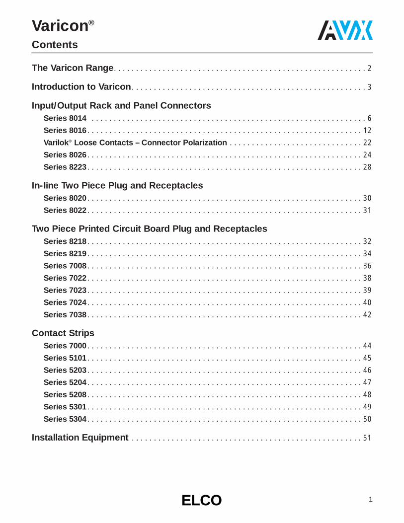
The Varicon Range
Pitch Number of Body Termination Current SeriesContacts Style Types Rating Number
(Amps)
0.050" 2 to 152 Plugs and Receptacles Staggered, Fixed: 5 8218Solder, Eyelet
0.050" 18, 30, 36, 42, 54, 72 Plugs and Receptacles Staggered, Fixed: Straight & 5 8219Right Angle Solder, Eyelet
Staggered,0.075" x 0.130" Removable: Taper Tab,
& 20, 38, 56, 90, 120 Plugs and Receptacles Eyelet, 8 80160.075" x 0.150" Wire Wrap,
Crimp
0.100" 17, 23, 29, 35, 41 Receptacles As Series 7024 8 7008
0.100" 17, 23, 29, 35, 41, 47 PlugsStaggered,
6 7022Fixed: Solder
0.100" 17, 23, 29, 35, 41, 47 ReceptaclesStaggered,
6 7023Fixed: Solder
Staggered,Fixed: Solder,
0.100" 17, 23, 29, 35, 41 Receptacles Taper Tab, 8 7024Eyelet,Wire Wrap,Bus Line
Staggered,Removable: Taper Tab,
0.100" 17, 23, 29, 35, 41, 47 Receptacles Eyelet, 8 7038Wire Wrap,Crimp
0.100" 33, 75, 117, 165 Plugs and Receptacles Wire Wrap, 5 8026Crimp
Square Grid Dual Row,Fixed: Straight and Right
0.100" 24, 48, 72, 96 Plugs and Receptacles Angle Solder, 5 8223Eyelet,Wire Wrap, CrimpWrappable Removable
4mm 50, 64 Plug and Receptacle Crimp 2 8014
In-line0.200" 2, 3 Plugs and Receptacles Fixed: Solder 8.5 8020
Crimp
In-line0.200" 3 Plug and Receptacle Fixed: Solder 8.5 8022
Crimp

3ELCOELCO
Varicon®
Introduction
Elco’s Varicon product range is available as two-piece input /output and board level connectors (intermateable plugs and receptacles). Varicon contacts are also available in strips, ondisposable carriers, ready for staking to p.c. cards. They alluse the famous, fork-like Varicon® (fixed) or Varilok®
(insertable / removable) hermaphroditic contact design.Elco’s range conforms to MIL-E-5400, MIL-E-8189 and MIL-T-21200. Varicon® (fixed contact) conforms to MIL-C-21097, Varilok® (insertable / removable) under MIL-C-28731, and Mini-Varilok® under MIL-C-55302.
VARICON DESIGN ADVANTAGESElco’s hermaphroditic Varicon contact utilizes a fork-likedesign incorporating four large mating surfaces that arecoined to achieve exceptional hardness and smoothness.The mating surfaces are wedged together by the spring-likedesign of the contact and by the innate properties of thecontact material. The Varicon contact has proven its reliabil-ity in innumerable applications and with over one-million con-tacts being produced daily, billions of successful, trouble-freeoperating hours have been logged.
FEATURES• Four intimate contact areas, electrically parallel• High current carrying capability, excellent heat dissipation• Self-cleaning, wiping action burnishes contacting surfaces
reducing constrictive resistance• Low contact resistance 3 to 4 milliohms• Stable in vibration and adverse environments• High contact normal pressure achieved at low stress
levels
HIGH RELIABILITYThe mating surfaces provide a gas-tight connection andresists corrosion caused by adverse environments. This sealis made possible by the spring-like properties of the Variconcontact and by the smoothness of the coined mating surfaces. After being mated for years, the contacts still retainclean, unoxidized mating surfaces.
LOW RESISTANCEBecause of the spring-like properties of the Varicon contact,both sides of the contact are always under considerablepressure when mated. Their sliding and wiping action burnishes the surfaces in a self-cleaning action reducing anyconstrictive resistance. The low contact resistance remains a permanent feature of the Varicon contact even after thou-sands of mating and unmating cycles.
HIGH CURRENT CAPACITYThe low contact resistance contributes substantially toVaricon’s high current-carrying capacitor. Also, its heat-dissi-pating characteristics are enhanced by its flat configuration.
SHOCK AND VIBRATION RESISTANCEShould external forces cause any decrease in contact pres-sure between two of the four mating surfaces, it is automat-ically compensated by redistributing the contact pressurebetween the other two mating surfaces.
ECONOMYVaricon contacts are stamped from sheet stock instead ofscrew-machined. Consequently, this production method notonly increases the production capacity but decreases pro-duction cost as there is little waste.
VERSATILITYThe Varicon concept can be used in a card-mounted plugthat mates with a receptacle, or Varicon contacts can bestaked directly to a pc board and soldered into place. Thislatter method eliminates the need for a conventional plugreducing the cost of the connection system while retainingthe proven reliability of the Varicon interconnection.
CONTACT TYPESTwo basic sizes of our Varicon contact are available: stan-dard and miniature Varicon. And each size has two majorvariations: the fixed Varicon contact and the Varilokinsertable / removable version. The standard size is rated at8 amps and has a withdrawal force range of 2 to 16 ouncesper contact. The miniature size is specifically for high densi-ty applications and is rated at 5 amps with a withdrawal forceof 2 to 8 ounces per contact. (For exact specifications, checkthe individual series listing.)
Miniature Varicon®
Approx. 2X Actual Size
Standard Varicon®

4 ELCOELCO
Varicon®
Introduction
CONTACT MATERIALThe primary contact material used is phosphor bronze. Theelectrical conductivity of copper alloys are extremely good.Within the Varicon concept, the contacts must also performas springs and these alloys offer the elastic properties andthe endurance required by today’s rugged applications.
CONTACT PLATINGA nickel underplate of 50 to 100 microinches, followed by aminimum of 10 microinches of gold plate is Elco’s standardcontact plating. The gold plate prevents the formation ofinsulating oxide films while the nickel plate provides a hardbacking. It, in turn, reduces wear on the gold and preventsdiffusion between the gold and base metal. Other platingthicknesses, such as those required by military specifica-tions, can be supplied on request.
VARILOK CRIMP-AND-INSERT CONTACTSThe crimp-termination, insertable / removable Varilok contactoffers a solderless connection between wire and contact aswell as strain relief for the wire. This contact snaps into theinsulator quickly and easily. With our simple tool it can beremoved without difficulty, yet it locks securely into place andcannot twist or bend out of alignment.
Varilok contacts also are available with wire-wrappable, solderand taper-tab tail configurations. Available loose for smallscale production and replacement purposes, the Varilokcontact is also supplied on reels for use with fast, economi-cal automatic crimping machines reducing man-hourrequirements and production costs in medium and large-scale production runs. Because the contact can be crimpedto the wire and installed into the insulator at any point duringthe manufacturing operation, it offers the user convenienceand flexibility. Reels contain 1800 standard contacts or 3000miniature contacts.
Loose Varilok Contacts
Reel-Mounted Varilok Contacts

MINI-VARILOKThe Mini-Varilok is half the size of the standard Varilok contact. It’s designed for hand or machine crimping to solidor stranded AWG #22 to #30 wire. Its basic features areidentical to the standard Varilok however it also incorporatesa decreased insertion force and is used for high densityapplications. Production methods for the Mini-Varilok are thesame as the standard Varilok.
CONTACT RETENTIONThe Varilok contact, after undergoing five insertion / extrac-tion cycles and being subjected to the vibration and shocktests of MIL-C-28731, still withstands an axial load in excessof 10 pounds (6 for mini-varilok).
WIRE SIZEThe Varilok contact with its open crimp barrel conforms topractically all specifications written for screw-machined con-tacts with closed crimp barrels. The crimp barrel of theVarilok contact is designed to accommodate wire sizes AWG#18 to #26. It’s also possible to crimp together two strand-ed #22 or smaller wires. The Mini-Varilok accommodateswire sizes AWG #22 to #30. Table I lists the various sizes ofwire to which Varilok contacts can be crimped, and indicatesthe minimum conductor diameter and the maximum insula-tor diameter that can be accommodated by the contacts.The crimp barrel is also crimped to the wire’s insulation forstrain relief and the large, overlapping ears of the barrelaccommodate a wide range of wire insulation sizes (Table I).For an optimum crimp connection, the insulation is strippedone-eighth inch from the end of the conductor.
Table IWire Sizes
(AWG)(Ref: MIL-W-16878/4 – Type E wire)
CRIMP CHARACTERISTICSThe illustration shows an enlarged cross-section of a typicalVarilok crimp on a #22 stranded wire. No significant voids are visible. The complete deformation of the wire strandsindicates optimum contact between the contact barrel andthe conductors.
TENSILE STRENGTHTable II lists the values, in pounds, of tensile strength (wirepull-out force) for Varilok and Mini-Varilok contacts crimpedto stranded AWG #18 to #30 wires.
Table IITensile Strength
(In Pounds)
CRIMPING EQUIPMENTAll equipment needed to crimp Varilok and Mini-Varilok contacts is normally available from stock. Crimping equip-ment for production crimping as well as hand-operatedcrimping pliers are designed to realize the full electrical,mechanical and economical advantages of the Varilok andMini-Varilok contact.
5ELCOELCO
Varicon®
Introduction
Conductor InsulatorSingle Varilok Mini-Varilok Diameter DiameterWire (Nominal) (Max. Overall)
#18 Yes No .048 .074#20 Yes No .038 .062#22 Yes Yes .030 .054#24 Yes Yes .024 .048#26 Yes Yes .019 .043#28 No Yes .015 .039#30
No Yes .012 .036(Stranded)
Wire Size(AWG)
#18 #20 #22 #24 #26 #28 #30
StrandedWire
40 25 15 10 5 3 1.5

6 ELCOELCO
Varicon®
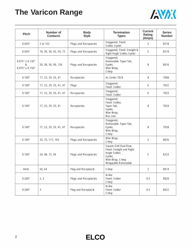
Series 8014
Elco has introduced a new, metric version of the famousVaricon connector. The wire to board 8014 series is availablein 50 or 64 positions and suitable for use in a VME front plate.The Varicon contact is well known for high reliability anddurability under all conditions. Contacts are specified at 2amps and low contact resistance. In the 8014 series, thefamiliar hermaphroditic contact is shrouded on both sides toprotect and guide the contact to a perfect mating. Board termination is right angle or vertical to plated through holes.The connectors have actuating screws to assist mating andunmating and to provide secure attachment. The covershave integral cable clamps. The 50 position cover is plasticand 64 position is die cast aluminum.
TECHNICAL SPECIFICATIONS MATERIAL / FINISHNumber of Contacts:50, 64
Contact Spacing:4.0mm
Current Rating:2Amp/pin
Voltage Rating:125V
Dielectric WithstandingVoltage:2000V rms/min.
Durability:200 cycle
Applicable Wire Size:
AWG #18~#26
Operating Temperature:-55~+105°C
Insulator:Plug PBTRec. PBT
Contact:Phosphor BronzeFinish / Gold over Nickel
Hardware:see individual drawing

7ELCOELCO
Varicon®
Series 8014
10 8014 264 XXX
Variation 1 /Contact Code
000 = No contact loaded100 = Wire crimp contact
(loose pieces attached)200 = Straight through hole
XXX
Variation 2 /Finish, Color
000 = without cover, center-screw, green insulator
100 = with cover, center-screw, green insulator
ORDERING CODE (64 pos. Center-Screw Type Plug)

8 ELCOELCO
Varicon®
Series 8014
ORDERING CODE (64 pos. Center-Screw Type Receptacle)
20 8014 264 XXX
Variation 1 /Contact Code
000 = No contact loaded100 = Wire crimp contact
(loose pieces attached)200 = Straight through hole999 = Right angle through
hole
XXX
Variation 2 /Finish, Color
000 = R/A through hole, center lock nut, green insulator
100 = ST through hole, center lock nut, green insulator

9ELCOELCO
Varicon®
Series 8014
ORDERING CODE (50 pos. Side-Screw, Plug)
10 8014 350 XXX
Variation 1 /Contact Code
000 = No contact loaded100 = Wire crimp contact
(loose pieces attached)200 = Straight through hole
XXX
Variation 2 /Finish, Color
028 = Side-screw, gray insulator
128 = Side-screw,gray insulator with cover
(038 = Side-short-screw,gray insulator. . . .special)
10 ELCOELCO
Varicon®
Series 8014
20 8014 350 999
Variation 1 /Contact Code
999 = Right angle throughhole
028
Variation 2 /Finish, Color
028 = Side-screw, gray insulator
ORDERING CODE (50 pos. Side-Screw Receptacle)
70 8014 000 000 858
Finish Code858 = 10 microinches
Gold over Nickel Plate
ORDERING CODE (Crimp Contact)

11ELCOELCO
Varicon®
Series 8014
30 8014 001 000 225
ORDERING CODE (Cover, 64 pos. Center-Screw, Aluminum Die Cast)
30 8014 001 003 008
ORDERING CODE (50 pos. Side-Screw, Plastic (gray))

Contact Termination
*000 = Contacts not fitted and ordered separately, see page 22 for full list of options
217 = Solder 0.098" x 2.49mm
218 = Wire Wrap –
0.025 x 0.050 x 0.567" / 0.64 x 1.27 x 14.4mm
296 = Wire Wrap –
0.025 x 0.026 x 0.579" / 0.64 x 1.27 x 19.3mm
504 = Solder Tail –
750 = Wire Wrap –
0.025 x 0.050 x 0.760" / 0.64 x 1.27 x 19.3mm
12 ELCOELCO
Plug
001/501/601
002/502/602
903/503/603
904/504/604
905/505/605
906/506/606
Varicon®
Series 8016 – Rectangular Connector – 20 Way
ORDERING CODE
PLUGActuating
Screw
PLUGFixed Nut
SOCKETActuating
Screw
SOCKETFixedNut
007/
507/
607
008/
508/
608
909/
509/
609
910/
510/
610
911/
511/
611
912/
512/
612
Rec
epta
cle
CONNECTOR PLUG ANDRECEPTACLE COMBINATIONS
European Version USA Versions CoverInsulator Grey Polyester Grey Polyester Green Polyester and Actu-
Body Aluminum No No No Cable ating FixedType Cover Cover Cover Cover Cover Cover Entrance Screw Nut
— 001 — 501 601 None Yes No— 002 — 502 602 None No YesMale 903 — 503 603 Top* Yes No(Exposed
904 — 504 604 Side* Yes NoContacts)905 — 505 605 Top* No Yes906 — 506 606 Side* No Yes— 007 507 607 None No Yes— 008 508 608 None Yes NoFemale
909 — 509 — 609 — Top* Yes No(Recessed910 — 510 — 610 — Side* Yes NoContacts)911 — 511 — 611 — Top* No Yes912 — 512 — 612 — Side* No Yes
00
Prefix
8016
SeriesNumber
020
Number ofContacts
217 001
SeeVariation
Code
VARIATION CODE
Select variation code combinations marked with square in the table.
*These covers should only be used with crimp contacts.
*Crimp contacts always ordered separately.See page 22 for details.
PIN LAYOUT20
Way
13ELCOELCO
Varicon®
Series 8016 – Rectangular Connector – 20 Way
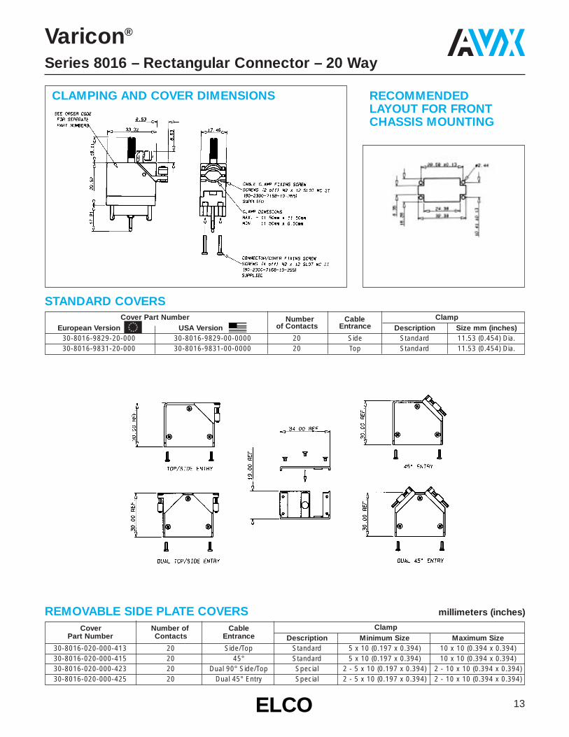
CLAMPING AND COVER DIMENSIONS RECOMMENDEDLAYOUT FOR FRONTCHASSIS MOUNTING
STANDARD COVERSCover Part Number Number Cable Clamp
European Version USA Version of Contacts Entrance Description Size mm (inches)30-8016-9829-20-000 30-8016-9829-00-0000 20 Side Standard 11.53 (0.454) Dia.30-8016-9831-20-000 30-8016-9831-00-0000 20 Top Standard 11.53 (0.454) Dia.
REMOVABLE SIDE PLATE COVERS millimeters (inches)
Cover Number of Cable ClampPart Number Contacts Entrance Description Minimum Size Maximum Size
30-8016-020-000-413 20 Side/Top Standard 5 x 10 (0.197 x 0.394) 10 x 10 (0.394 x 0.394)30-8016-020-000-415 20 45° Standard 5 x 10 (0.197 x 0.394) 10 x 10 (0.394 x 0.394)30-8016-020-000-423 20 Dual 90° Side/Top Special 2 - 5 x 10 (0.197 x 0.394) 2 - 10 x 10 (0.394 x 0.394)30-8016-020-000-425 20 Dual 45° Entry Special 2 - 5 x 10 (0.197 x 0.394) 2 - 10 x 10 (0.394 x 0.394)

European Version USA ONLY Versions Cover & Actu-Insulator Grey Polyester Grey Polyester Green Polyester Cable ating Fixed
Body Type Aluminum Cover No Cover Aluminum Cover No Cover Aluminum Cover No Cover Entrance Screw NutStd. Large Ex-Large Std. Large Ex-Large Std. Large Ex-Large
Clamp Clamp Clamp Clamp Clamp Clamp Clamp Clamp Clamp— — — 001 — — — 501 — — — 601 None Yes No— — — 002 — — — 502 — — — 602 None No YesMale 903 919 931 — 503 519 531 — 603 619 631 — Top Yes No(Exposed
904 920 932 — 504 520 532 — 604 620 632 — Side Yes NoContacts)905 921 933 — 505 521 533 — 605 621 633 — Top No Yes906 922 934 — 506 522 534 — 606 622 634 — Side No Yes— — 007 — — — 507 — — — 607 None No Yes— — 008 — — — 508 — — — 608 None Yes No
Female 909 923 935 — 509 523 535 — 609 623 635 — Top Yes No(Recessed 910 924 936 — 510 524 536 — 610 624 636 — Side Yes NoContacts) 911 925 937 — 511 525 537 — 611 625 637 — Top No Yes
912 926 938 — 512 526 538 — 612 626 638 — Side No Yes
Plug
001/501/601002/502/602
903/503/603904/504/604905/505/605906/506/606
919/519/619920/520/620921/521/621922/522/622
931/531/631932/532/632933/533/633934/534/634
14 ELCOELCO
Varicon®
Series 8016 – Rectangular Connector – 38 Way
00
Prefix
8016
SeriesNumber
038
Number ofContacts
217 001
SeeVariation
Code
ORDERING CODE
PLUGActuating
Screw
PLUGFixed Nut
SOCKETActuating
Screw
SOCKETFixedNut
007/
507/
607
008/
508/
608
909/
509/
609
910/
510/
610
911/
511/
611
912/
512/
612
923/
523/
623
924/
524/
624
925/
525/
625
926/
526/
626
935/
535/
635
936/
536/
636
937/
537/
637
938/
538/
638
Rece
ptac
le
CONNECTOR PLUG ANDRECEPTACLE COMBINATIONS
VARIATION CODE
Select variation code combinations marked with square in the table.
Contact Termination
*000 = Contacts not fitted and ordered separately, see page 22 for full list of options
217 = Solder 0.098" x 2.49mm
218 = Wire Wrap –
0.025 x 0.050 x 0.567" / 0.64 x 1.27 x 14.4mm
296 = Wire Wrap –
0.025 x 0.026 x 0.579" / 0.64 x 1.27 x 19.3mm
504 = Solder Tail –
750 = Wire Wrap –
0.025 x 0.050 x 0.760" / 0.64 x 1.27 x 19.3mm
*Crimp contacts always ordered separately.See page 22 for details.
PIN LAYOUT38
Way

15ELCOELCO
Varicon®
Series 8016 – Rectangular Connector – 38 Way
CLAMPING AND COVER DIMENSIONS RECOMMENDEDLAYOUT FOR FRONTCHASSIS MOUNTING
STANDARD COVERS
REMOVABLE SIDE PLATE COVERS millimeters (inches)
Cover Number of Cable ClampPart Number Contacts Entrance Description Minimum Size Maximum Size
30-8016-038-000-413 38 Side/Top Standard 6 x 14 (0.236 x 0.551) 17 x 14 (0.669 x 0.551)30-8016-038-000-415 38 45° Standard 6 x 14 (0.236 x 0.551) 17 x 14 (0.669 x 0.551)30-8016-038-000-423 38 Dual 90° Side/Top Special 2 - 6 x 14 (0.236 x 0.551) 2 - 17 x 14 (0.669 x 0.551)30-8016-038-000-425 38 Dual 45° Entry Special 2 - 6 x 14 (0.236 x 0.551) 2 - 17 x 14 (0.669 x 0.551)
Cover Part Number Number of Cable ClampEuropean Version USA Version Contacts Entrance Description Size mm (inches)30-8016-9821-20-000 30-8016-9821-00-0000 38 Side Standard 16.51 X 12.70 (0.650 x 0.500)30-8016-9822-20-000 30-8016-9822-00-0000 38 Top Standard 16.51 X 12.70 (0.650 x 0.500)30-8016-9825-20-000 30-8016-9825-00-0000 38 Side Large 16.51 X 15.44 (0.650 x 0.608)30-8016-9826-20-000 30-8016-9826-00-0000 38 Top Large 16.51 X 15.44 (0.650 x 0.608)30-8016-9838-20-000 30-8016-9838-00-0000 38 Side Extra-Large 20.83 X 15.60 (0.820 x 0.614)30-8016-9839-20-000 30-8016-9839-00-0000 38 Top Extra-Large 20.83 X 15.60 (0.820 x 0.614)
OPTIONAL REMOVABLE SIDE PLATE COVER

16 ELCOELCO
European Version USA ONLY Versions Cover & Actu-Insulator Grey Polyester Grey Polyester Green Polyester Cable ating Fixed
Body Type Aluminum Cover No Cover Aluminum Cover No Cover Aluminum Cover No Cover Entrance Screw NutStd. Large Ex-Large Std. Large Ex-Large Std. Large Ex-Large
Clamp Clamp Clamp Clamp Clamp Clamp Clamp Clamp Clamp— — — 001 — — — 501 — — — 601 None Yes No— — — 002 — — — 502 — — — 602 None No YesMale 903 919 931 — 503 519 531 — 603 619 631 — Top Yes No(Exposed
904 920 932 — 504 520 532 — 604 620 632 — Side Yes NoContacts)905 921 933 — 505 521 533 — 605 621 633 — Top No Yes906 922 934 — 506 522 534 — 606 622 634 — Side No Yes
— — 007 — — — 507 — — — 607 None No Yes— — 008 — — — 508 — — — 608 None Yes No
Female 909 923 935 — 509 523 535 — 609 623 635 — Top Yes No(Recessed 910 924 936 — 510 524 536 — 610 624 636 — Side Yes NoContacts) 911 925 937 — 511 525 537 — 611 625 637 — Top No Yes
912 926 938 — 512 526 538 — 612 626 638 — Side No Yes
Varicon®
Series 8016 – Rectangular Connector – 56 Way
00
Prefix
8016
SeriesNumber
056
Number ofContacts
217 001
SeeVariation
Code
ORDERING CODE
PLUG - Actuating Screw
PLUG – Fixed Nut
SOCKET - Actuating Screw
SOCKET – Fixed Nut
PIN LAYOUT56
Way
VARIATION CODE
Plug
001/501/601002/502/602
903/503/603904/504/604905/505/605906/506/606
919/519/619920/520/620921/521/621922/522/622
931/531/631932/532/632933/533/633934/534/634
007/
507/
607
008/
508/
608
909/
509/
609
910/
510/
610
911/
511/
611
912/
512/
612
923/
523/
623
924/
524/
624
925/
525/
625
926/
526/
626
935/
535/
635
936/
536/
636
937/
537/
637
938/
538/
638
Rece
ptac
le
CONNECTOR PLUG ANDRECEPTACLE COMBINATIONS
Select variation code combinations marked with square in the table.
Contact Termination
*000 = Contacts not fitted and ordered separately, see page 22 for full list of options
217 = Solder 0.098" x 2.49mm
218 = Wire Wrap –
0.025 x 0.050 x 0.567" / 0.64 x 1.27 x 14.4mm
296 = Wire Wrap –
0.025 x 0.026 x 0.579" / 0.64 x 1.27 x 19.3mm
504 = Solder Tail –
750 = Wire Wrap –
0.025 x 0.050 x 0.760" / 0.64 x 1.27 x 19.3mm
*Crimp contacts always ordered separately.See page 22 for details.

17ELCOELCO
Varicon®
Series 8016 – Rectangular Connector – 56 Way
CLAMPING AND COVER DIMENSIONS RECOMMENDEDLAYOUT FOR FRONTCHASSIS MOUNTING
STANDARD COVERS
OPTIONAL REMOVABLE SIDE PLATE COVER
REMOVABLE SIDE PLATE COVERS millimeters (inches)
Cover Number of Cable ClampPart Number Contacts Entrance Description Minimum Size Maximum Size
30-8016-056-000-413 56 Side/Top Standard 6 x 14 (0.236 x 0.551) 17 x 14 (0.669 x 0.551)30-8016-056-000-415 56 45° Standard 6 x 14 (0.236 x 0.551) 17 x 14 (0.669 x 0.551)30-8016-056-000-423 56 Dual 90° Side/Top Special 2 - 6 x 14 (0.236 x 0.551) 2 - 17 x 14 (0.669 x 0.551)30-8016-056-000-425 56 Dual 45° Entry Special 2 - 6 x 14 (0.236 x 0.551) 2 - 17 x 14 (0.669 x 0.551)
Cover Part Number Number of Cable ClampEuropean Version USA Version Contacts Entrance Description Size mm (inches)30-8016-9823-20-000 30-8016-9823-00-0000 56 Side Standard 16.51 X 12.70 (0.650 x 0.500)30-8016-9824-20-000 30-8016-9824-00-0000 56 Top Standard 16.51 X 12.70 (0.650 x 0.500)30-8016-9827-20-000 30-8016-9827-00-0000 56 Side Large 16.51 X 15.44 (0.650 x 0.608)30-8016-9828-20-000 30-8016-9828-00-0000 56 Top Large 16.51 X 15.44 (0.650 x 0.608)30-8016-9840-20-000 30-8016-9840-00-0000 56 Side Extra-Large 20.83 X 15.60 (0.820 x 0.614)30-8016-9842-20-000 30-8016-9842-00-0000 56 Top Extra-Large 20.83 X 15.60 (0.820 x 0.614)

18 ELCOELCO
European Version USA ONLY Versions Cover & Actu-Insulator Grey Polyester Grey Polyester Green Polyester Cable ating Fixed
Body Type Cover Cover Cover Cover Cover Cover Entrance Screw NutLarge Ex-Large Large Ex-Large Large Ex-LargeClamp Clamp Clamp Clamp Clamp Clamp
— — 001 — — 501 — — 601 None Yes No— — 002 — — 502 — — 602 None No YesMale 903 931 — 503 531 — 603 631 — Top Yes No(Exposed
904 932 — 504 532 — 604 632 — Side Yes NoContacts)905 933 — 505 533 — 605 633 — Top No Yes906 934 — 506 534 — 606 634 — Side No Yes
— — 007 — — 507 — — 607 None No Yes— — 008 — — 508 — — 608 None Yes No
Female 909 935 — 509 535 — 609 635 — Top Yes No(Recessed 910 936 — 510 536 — 610 636 — Side Yes NoContacts) 911 937 — 511 537 — 611 637 — Top No Yes
912 938 — 512 538 — 612 638 — Side No Yes
Varicon®
Series 8016 – Rectangular Connector – 90 Way
00
Prefix
8016
SeriesNumber
090
Number ofContacts
217 001
SeeVariation
Code
ORDERING CODE
PLUG - Actuating Screw
PLUG – Fixed Nut
SOCKET - Actuating Screw
SOCKET – Fixed Nut
PIN LAYOUT90
Way
CONNECTOR PLUG ANDRECEPTACLE COMBINATIONS
VARIATION CODE
Plug
001/501/601002/502/602
903/503/603904/504/604905/505/605906/506/606
931/531/631932/532/632933/533/633934/534/634
007/
507/
607
008/
508/
608
909/
509/
609
910/
510/
610
911/
511/
611
912/
512/
612
935/
535/
635
936/
536/
636
937/
537/
637
938/
538/
638
Rece
ptac
le
Select variation code combinations marked with square in the table.
Contact Termination
*000 = Contacts not fitted and ordered separately, see page 22 for full list of options
217 = Solder 0.098" x 2.49mm
218 = Wire Wrap –
0.025 x 0.050 x 0.567" / 0.64 x 1.27 x 14.4mm
296 = Wire Wrap –
0.025 x 0.026 x 0.579" / 0.64 x 1.27 x 19.3mm
504 = Solder Tail –
750 = Wire Wrap –
0.025 x 0.050 x 0.760" / 0.64 x 1.27 x 19.3mm
*Crimp contacts always ordered separately.See page 22 for details.

19ELCOELCO
Varicon®
Series 8016 – Rectangular Connector – 90 Way
CLAMPING AND COVER DIMENSIONS RECOMMENDEDLAYOUT FOR FRONTCHASSIS MOUNTING
STANDARD COVERS
OPTIONAL REMOVABLE SIDE PLATE COVER
REMOVABLE SIDE PLATE COVERS millimeters (inches)
Cover Number of Cable ClampPart Number Contacts Entrance Description Minimum Size Maximum Size
30-8016-090-000-413 90 Side/Top Standard 7 x 21 (0.276) 21 x 21 (0.827 x 0.827)30-8016-090-000-415 90 45° Standard 7 x 21 (0.276) 21 x 21 (0.827 x 0.827)30-8016-090-000-423 90 Dual 90° Side/Top Special 2 - 7 x 21 (0.276) 2 - 21 x 21 (0.827 x 0.827)30-8016-090-000-425 90 Dual 45° Entry Special 2 - 7 x 21 (0.276) 2 - 21 x 21 (0.827 x 0.827)
Cover Part Number Number of Cable ClampEuropean Version USA Version Contacts Entrance Description Size mm (inches)30-8016-9832-20-000 30-8016-9832-00-0000 90 Side Large 20.32 (0.800) Dia.30-8016-9833-20-000 30-8016-9833-00-0000 90 Top Large 20.32 (0.800) Dia.30-8016-9843-20-000 30-8016-9843-00-0000 90 Side Extra-Large 25.40 x 20.32 (1.00 x 0.008)30-8016-9844-20-000 30-8016-9844-00-0000 90 Top Extra-Large 25.40 x 20.32 (1.00 x 0.008)

20 ELCOELCO
European Version USA ONLY Versions Cover & Actu-Insulator Grey Polyester Grey Polyester Green Polyester Cable ating Fixed
Body Type Cover Cover Cover Cover Cover Cover Entrance Screw NutLarge Ex-Large Large Ex-Large Large Ex-LargeClamp Clamp Clamp Clamp Clamp Clamp
— — 001 — — 501 — — 601 None Yes No— — 002 — — 502 — — 602 None No YesMale 903 931 — 503 531 — 603 631 — Top Yes No(Exposed
904 932 — 504 532 — 604 632 — Side Yes NoContacts)905 933 — 505 533 — 605 633 — Top No Yes906 934 — 506 534 — 606 634 — Side No Yes
— — 007 — — 507 — — 607 None No Yes— — 008 — — 508 — — 608 None Yes No
Female 909 935 — 509 535 — 609 635 — Top Yes No(Recessed 910 936 — 510 536 — 610 636 — Side Yes NoContacts) 911 937 — 511 537 — 611 637 — Top No Yes
912 938 — 512 538 — 612 638 — Side No Yes
Varicon®
Series 8016 – Rectangular Connector – 120 Way
00
Prefix
8016
SeriesNumber
120
Number ofContacts
217 001
SeeVariation
Code
ORDERING CODE
PLUG - Actuating Screw
PLUG – Fixed Nut
SOCKET - Actuating Screw
SOCKET – Fixed Nut
PIN LAYOUT120Way
CONNECTOR PLUG ANDRECEPTACLE COMBINATIONS
VARIATION CODE
Plug
001/501/601002/502/602
903/503/603904/504/604905/505/605906/506/606
931/531/631932/532/632933/533/633934/534/634
007/
507/
607
008/
508/
608
909/
509/
609
910/
510/
610
911/
511/
611
912/
512/
612
935/
535/
635
936/
536/
636
937/
537/
637
938/
538/
638
Rece
ptac
le
Select variation code combinations marked with square in the table.
Contact Termination
*000 = Contacts not fitted and ordered separately, see page 22 for full list of options
217 = Solder 0.098" x 2.49mm
218 = Wire Wrap –
0.025 x 0.050 x 0.567" / 0.64 x 1.27 x 14.4mm
296 = Wire Wrap –
0.025 x 0.026 x 0.579" / 0.64 x 1.27 x 19.3mm
504 = Solder Tail –
750 = Wire Wrap –
0.025 x 0.050 x 0.760" / 0.64 x 1.27 x 19.3mm
*Crimp contacts always ordered separately.See page 22 for details.
21ELCOELCO
Varicon®
Series 8016 – Rectangular Connector – 120 Way
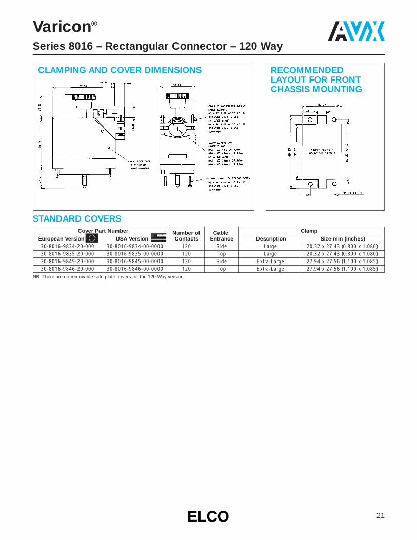
CLAMPING AND COVER DIMENSIONS RECOMMENDEDLAYOUT FOR FRONTCHASSIS MOUNTING
STANDARD COVERSCover Part Number Number of Cable Clamp
European Version USA Version Contacts Entrance Description Size mm (inches)30-8016-9834-20-000 30-8016-9834-00-0000 120 Side Large 20.32 x 27.43 (0.800 x 1.080)30-8016-9835-20-000 30-8016-9835-00-0000 120 Top Large 20.32 x 27.43 (0.800 x 1.080)30-8016-9845-20-000 30-8016-9845-00-0000 120 Side Extra-Large 27.94 x 27.56 (1.100 x 1.085)30-8016-9846-20-000 30-8016-9846-00-0000 120 Top Extra-Large 27.94 x 27.56 (1.100 x 1.085)
NB: There are no removable side plate covers for the 120 Way version.
22 ELCOELCO
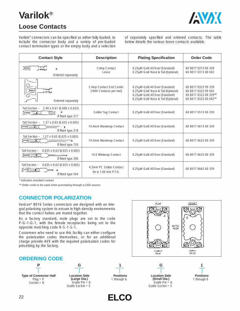
Contact Style Description Plating Specification Order Code
* Crimp Contact 0.25µM Gold All Over (Standard) 60 8017 0313 00 339Loose 0.25µM Gold Nose & Tail (Optional) 60 8017 0313 00 042
Crimp Contact End Carrier 0.25µM Gold All Over (Standard) 60 8017 0323 99 339(1800 Contacts per reel) 0.25µM Gold Nose & Tail (Optional) 60 8017 0323 99 042
0.25µM Gold All Over (Standard) 60 8017 0323 00 339**0.25µM Gold Nose & Tail (Optional) 60 8017 0323 00 042**
Tail Section – 2.49 x 0.61 (0.098 x 0.024)Solder Tag Contact 0.25µM Gold All Over (Standard) 60 8017 0513 00 339*
Tail Section – 1.27 x 0.63 (0.025 x 0.005)14.4mm Maxiwrap Contact 0.25µM Gold All Over (Standard) 60 8017 0613 00 339
Tail Section – 1.27 x 0.63 (0.025 x 0.005)19.3mm Maxiwrap Contact 0.25µM Gold All Over (Standard) 60 8017 0623 00 339
Tail Section – 0.635 x 0.63 (0.025 x 0.005)14.0 Miniwrap Contact 0.25µM Gold All Over (Standard) 60 8017 0633 00 339
Tail Section – 0.635 x 0.63 (0.025 x 0.005)4.3mm PC Solder Contact 0.25µM Gold All Over (Standard) 60 8017 0663 00 339
* for ø 1.00 mm P.T.H.
Varilok®
Loose Contacts
* Indicates standard contact
** Order code to be used when purchasing through a USA source.
Varilok® connectors can be specified as either fully loaded, toinclude the connector body and a variety of pre-loaded contact termination types or the empty body and a selection
of separately specified and ordered contacts. The tablebelow details the various loose contacts available.
P
Type of Connector HalfPlug = P
Socket = R
G
Location Side(Large Dia.)Guide Pin = G
Guide Socket = S
1
Positions1 through 6
G
Location Side(Small Dia.)Guide Pin = G
Guide Socket = S
1
Positions1 through 6
ORDERING CODE
Varicon® 8016 Series connectors are designed with an inte-gral polarizing system to ensure in high density environmentsthat the correct halves are mated together.As a factory standard, male plugs are set to the code P-G-1-G-1, with the female receptacles being set to theopposite matching code R-S-1-S-1.Customers who need to use this facility can either configurethe polarization codes themselves, or for an additionalcharge provide AVX with the required polarization codes forpresetting by the factory.
CONNECTOR POLARIZATION
Ordered separately
Ordered separately
If fitted type 217
If fitted type 218
If fitted type 750
If fitted type 296
If fitted type 504

23ELCOELCO
CONTACT INSERTION TOOLSThese are small hand tools which provide a positive methodfor inserting contacts into the rear of the insulator by applyingpressure on the contacts directly to the end of the insulationcrimp.
HAND CRIMP TOOLThis tool is designed for hand crimping of contacts. The toolis well suited for maintenance, model shop, laboratory andsmall scale production purposes. Two crimping cavities areavailable; Upper Cavity will crimp wire 18-20 AWG and theLower Cavity will crimp wire 22-26 AWG.
CONTACT EXTRACTION TOOLSThis tool is designed to extract contacts from the front of the insulator quickly and easily, without damage to eithercontacts or insulator.
CRIMPING MACHINESThese heavy duty crimping machines are designed for fast and economical production-line crimping of contactssupplied on reels. The machines incorporate the uniqueDIALMATIC crimp adjustment which permits the machineoperator to crimp contacts to wires of different sizes by simply adjusting two knobs.
SPECIFICATIONSPress Rating: 3 Ton CapacityPower: 240V AC, 50 Cycles
Varicon®
Tools
Tool Contact Capability06 1742 0400 00 000 Varilok®
No. 60 8017 Family06 7698 01 000 0000 Mini Varilok®
No. 60 8216 Family
Part No. Contact Capability Wire Type & Size06 7852 0100 00 000 Varilok® Stranded AWG
No. 60 8017 0313 No. 18-26Mini Varilok® Stranded AWG
06 7858 01 000 0000 No. 60 8216 0313 No. 22-30
Tool Contact Capability06 1877 0400 00 000 Varilok®
No. 60 8017 Family06 7699 01 000 0000 Mini Varilok®
No. 60 8216 Family
Part No. Contact Wire SizeHR-1 06 1984 0102 Varilok® AWG No. 18-26

24 ELCOELCO
Varicon®
Series 8026 – 0.100" Rectangular Connector
FEATURES• Economical miniature high-density connectors suitable for
high-reliability and military applications.• 0.100" (2.54mm) square grid rack and panel connectors
with male and female insulators are available in four sizes:33, 75, 117 and 165 contacts.
• Insertable / removable mini-varilok and mini-wrap contacts.• Crimp and/or solderless wrap terminations.• Exceptional versatility: all hardware can be mounted on
plug or receptacle (see ordering code).• Actuating screw facilitates mating and unmating; locks
mated connectors together.• Keyed and shrouded insulator design prevents incorrect
mating and protects contacts from mishandling.• Simplified polarizing hardware permits 36 polarization
combinations per connector pair.• Optional covers with top or side cable entry and clamp.• Optional cable clamps.• Choice of any combination of hardware — or no hardware.• U.L. recognized-diallyl phthalate material.• QPL approved-diallyl phthalate material.
Current Rating:5 amperes
Contact Resistance:6 milliohmsWithdrawal Force:2 to 8 ounces max. per contact
Material:Phosphor Bronze
Standard Plating:Gold, 10 microinches min., over Nickel, 50-100 microinches
Spacing:0.100" (2.54mm)
TECHNICAL SPECIFICATIONSCONTACTS INSULATORS
Insulation Resistance:5,000 megohms, min. (diallyl phthalate insulators)5,000 megohms, min. (polycarbonate insulators)
Dielectric WithstandingVoltage:Sea Level: 1,000 Volts rms
Materials:0.100" (2.54mm) spacing – diallyl phthalate, glass-filled, flame resistant
ORDERING CODE00 8026 033
Number ofContacts033 = 33 075 = 75 117 = 117165 = 165
000
Contact CodeOrder crimp contacts separately by Part Number.Otherwise specify contact code 491.
000 = Crimp (3000 - contact reel)
Part Number60 8216 0323 00 339
000 = Crimp (loose contact)
Accepts #22-30 AWG wire
Part Number60 8216 0313 00 339
491 = Wire wrappable removable contact .025"(.635mm) sq. x .564" (14.33mm) tail
Part Number60 8216 0413 00 339
803
Variation CodeAdd 050 to order alternative keying (Pin & Socket)
i.e. 701 = Standard hermaphroditic keying
751 = Pin and socket keying
Complete a 15 digit assembly number for each mating part, male and female.

25ELCOELCO
Insulator VariationBody Code
Actuating Fixed KeyingCover
Type No.Screw Nut Hardware
701 Yes No Yes No702 Yes No No NoMale703 No Yes Yes No(Exposed704 No Yes No NoContacts)733 No No Yes No734 No No No No801 No Yes Yes No802 No Yes No No Female803 Yes No Yes No (Recessed804 Yes No No No Contacts)833 No No Yes No 834 No No No No
Varicon®
Series 8026 – 0.100" Rectangular Connector
VARIATION CODES33 Contacts
Table 1Variation Code No.
Insulator Cover Cover Cable Actuating Fixed KeyingBody
WithoutSmall Large Entrance Screw Nut Hardware
TypeCover
Clamp Clamp701 — — No Yes No Yes702 — — No Yes No No703 — — No No Yes Yes704 — — No No Yes No733 — — No No No Yes734 — — No No No No— 705 713 Top Yes No Yes— 706 714 Side Yes No Yes
Male — 707 715 Top Yes No No(Exposed — 708 716 Side Yes No NoContacts) — 709 717 Top No Yes Yes
— 710 718 Side No Yes Yes— 711 719 Top No Yes No— 712 720 Side No Yes No— 735 739 Top No No Yes— 736 740 Side No No Yes— 737 741 Top No No No— 738 742 Side No No No
801 — — No No Yes Yes802 — — No No Yes No803 — — No Yes No Yes804 — — No Yes No No833 — — No No No Yes834 — — No No No No— 805 813 Top No Yes Yes— 806 814 Side No Yes Yes
Female — 807 815 Top No Yes No(Recessed — 808 816 Side No Yes NoContacts) — 809 817 Top Yes No Yes
— 810 818 Side Yes No Yes— 811 819 Top Yes No No— 812 820 Side Yes No No— 835 839 Top No No Yes— 836 840 Side No No Yes— 837 841 Top No No No— 838 842 Side No No No
75, 117 & 165 ContactsTable 3
Insulator VariationBody Code
Actuating Fixed KeyingCover
Type No.Nut Nut Hardware
Male 501 Yes No Yes No (Exposed 502 Yes No No No Contacts) 503 No Yes Yes No
504 No Yes No No601 No Yes Yes NoFemale602 No Yes No No (Recessed603 Yes No Yes No Contacts)604 Yes No No No
33 ContactsTable 2
Variation Code No.Insulator Cover Cover Cable Actuating Fixed Keying
BodyWithout
Small Large Entrance Nut Screw HardwareType
CoverClamp Clamp
501 — — No Yes No Yes502 — — No Yes No No503 — — No No Yes Yes504 — — No No Yes No— 505 513 Top Yes No Yes— 506 514 Side Yes No Yes
Male — 507 515 Top Yes No No(Exposed — 508 516 Side Yes No NoContacts) — 509 517 Top No Yes Yes
— 510 518 Side No Yes Yes— 511 519 Top No Yes No— 512 520 Side No Yes No
601 — — No No Yes Yes602 — — No No Yes No603 — — No Yes No Yes604 — — No Yes No No— 605 613 Top No Yes Yes— 606 614 Side No Yes Yes
Female — 607 615 Top No Yes No(Recessed — 608 616 Side No Yes NoContacts) — 609 617 Top Yes No Yes
— 610 618 Side Yes No Yes— 611 619 Top Yes No No— 612 620 Side Yes No No
Table 4

26 ELCOELCO
Varicon®
Series 8026 – 0.100" Rectangular Connector
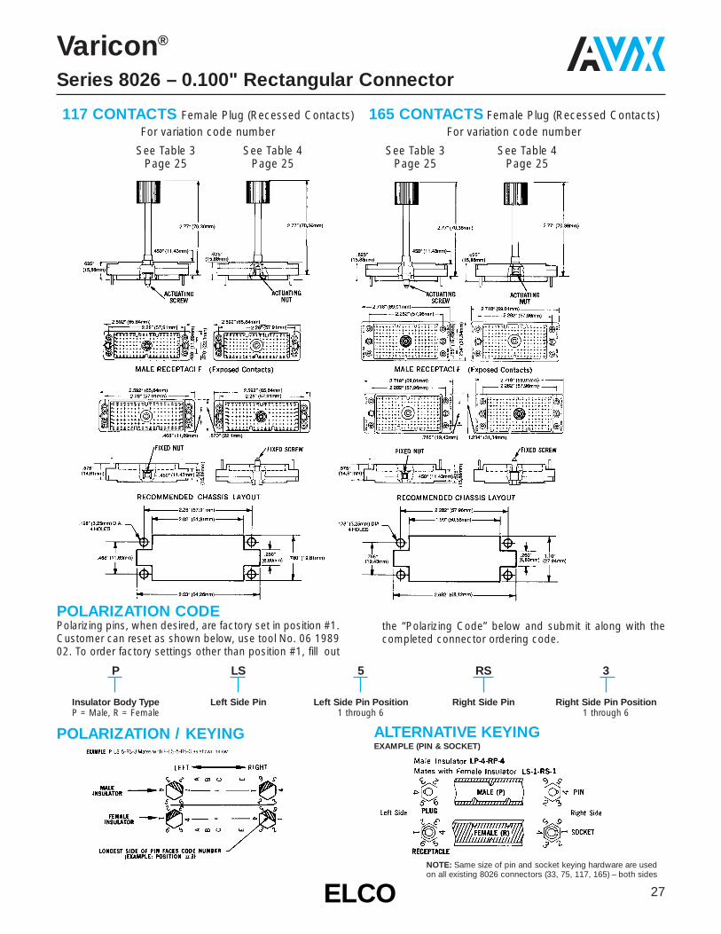
33 CONTACTSFemale Plug (Recessed Contacts)
For variation code numberSee Table 1 See Table 2
Page 25 Page 25
75 CONTACTSFemale Plug (Recessed Contacts)
For variation code numberSee Table 3 See Table 4
Page 25 Page 25
ClampCover Cable 8026/.100"Number Entrance Description (2.54mm) sq.
30-8016-9821 Side Small 75 Pin30-8016-9822 Top Small 75 Pin30-8016-9823 Side Small 117 Pin30-8016-9824 Top Small 117 Pin30-8016-9825 Side Large 75 Pin30-8016-9826 Top Large 75 Pin30-8016-9827 Side Large 117 Pin30-8016-9828 Top Large 117 Pin30-8016-9832 Side Large 165 Pin
ClampCover Cable 8026/.100"Number Entrance Description (2.54mm) sq.
30-8016-9833 Top Large 165 Pin30-8016-9838 Side Ex-Large 75 Pin30-8016-9839 Top Ex-Large 75 Pin30-8016-9840 Side Ex-Large 117 Pin30-8016-9842 Top Ex-Large 117 Pin30-8016-9843 Side Ex-Large 165 Pin30-8016-9844 Top Ex-Large 165 Pin30-8016-9845 Side Ex-Large —30-8016-9846 Top Ex-Large —
COVER CROSS REFERENCE, FOR DETAILS SEE 8016 CONNECTOR
27ELCOELCO
Varicon®
Series 8026 – 0.100" Rectangular Connector
POLARIZATION / KEYING ALTERNATIVE KEYINGEXAMPLE (PIN & SOCKET)
P
Insulator Body TypeP = Male, R = Female
LS
Left Side Pin
5
Left Side Pin Position1 through 6
RS
Right Side Pin
3
Right Side Pin Position1 through 6
POLARIZATION CODEPolarizing pins, when desired, are factory set in position #1.Customer can reset as shown below, use tool No. 06 198902. To order factory settings other than position #1, fill out
the “Polarizing Code” below and submit it along with thecompleted connector ordering code.
NOTE: Same size of pin and socket keying hardware are usedon all existing 8026 connectors (33, 75, 117, 165) – both sides
117 CONTACTS Female Plug (Recessed Contacts)For variation code number
See Table 3 See Table 4Page 25 Page 25
165 CONTACTS Female Plug (Recessed Contacts)For variation code number
See Table 3 See Table 4Page 25 Page 25

28 ELCOELCO
Code Profile Description Part No. H BoardFig.Dim. Thk.
Coined Tail Formed 60 8223 0223 .080 1000 90° after installing 60 8223 0213 .062
(Max. 0236 Diag.)Coined Tail Formed 60 8223 0243
.093 1000 90° after installing 60 8223 0253(Max. 0236 Diag.)
473P.C. Tail Coined
60 8223 0233 .400 2(Max. 0236 Diag.)
519P.C. Tail Coined
60 8223 0213 .279 2(Max. 0236 Diag.)
520P.C. Tail Coined
60 8223 0223 .479 2(Max. 0236 Diag.)558 P.C. Tail Coined 60 8223 0243 .309 2559 (Max. 0236 Diag.) 60 8223 0253 .509 2560 P.C. Tail Coined 60 8223 0263 .341 2561 (Max. 0236 Diag.) 60 8223 0273 .541 2
722Wire Hole Tail
60 8200 1613 .162 3(.032 x .050)
721 P.C. Tail .020 Sq. 60 8200 1623 .228 4
736 P.C. Tail .020 Sq. 60 8200 1633 .259 4
737 P.C. Tail .020 Sq. 60 8200 1643 .541 4
753 P.C. Tail .020 Sq. 60 8200 1653 .103 4
771 P.C. Tail .020 Sq. 60 8200 1663 .462 4
Crimp Contact5000 (Reel 3000) 60 8216 0323
22-30 AWG
000Crimp Contact (Loose)
60 8216 0313 522-30 AWG
491Wrappable/Removable
60 8216 0413 .560 6Contact (.025 Sq.)
Varicon®
Series 8223 – 0.100" Dual Row Square Grid
FEATURES• Wide range of contact terminations including wire
wrapping, P.C. solder tail, wire hole, wire crimp• For 1⁄16", 3⁄32" P.C. card• Polarity and keying are built into the connector body
to prevent mismating• Perpendicular or parallel connector mounting• Proven Varicon® contact reliability• Protected male; recessed female contacts• Conforms to MIL-C-55302 QPL
Current Rating:5 amperes with 22 AWG wire
Contact Resistance:6 milliohms, maximum
Contact Material and Plating:Phosphor BronzeNickel plate, 50 to 100 micro-inches, followed by gold plate.10 microinches minimum
Material:Diallyl Phthalate, glass-filled,flame resistant, per MIL-M-14-F,Type SDGF
Insulation Resistance:5,000 megohms, minimum
Dielectric WithstandingVoltage:Sea Level: 1,000 Volts rms
Insertion/Withdrawal Force:2 to 8 ounces per contact
TECHNICAL SPECIFICATIONS CONTACTS INSULATORS
ORDERING CODE00 8223 024 000
Contact Code
001Variation CodeNumber of Contacts
024, 048, 072 & 096
AccessoriesGuide Pins Sockets (R) Refer
InsulatorVariation Contact Style Threaded To Board
Type Cover Bracket Keying Locking Lkg. Kyg. Figure Thickness
001 Formed Contact Terminal X 1.080 2.03.062 1.57
PC Terminal X 2002 Wire Hole Terminal X 3
PC Straight Terminal X 4Crimp Contact X 5
Male 003 Wrappable Removable X 6(Exposed 004 Formed Contact Terminal X 1 .093 2.36Contacts) 006 Similar to 001 X 7
007 X 8008 Similar to 002 X 7009 X 8016 Similar to 004 X 7017 X 8018 Similar to 006 X 7019 X 8
901 Formed Contact Terminal X 1.080 2.03.062 1.57
PC Terminal X 2902 Wire Hole Terminal X 3
PC Straight Terminal X 4Crimp Contact X 5
903 Wrappable Removable X 6Female 904 Formed Contact Terminal X 1 .093 2.36
(Exposed 906 Similar to 901 X 15Contacts) 907 X 16
908 Similar to 902 X 15909 X 16916 Similar to 904 X 15917 X 16918 Similar to 905 X 15919 X 16
Use three digit code number when contacts are tobe factory installed. If contacts are to be suppliedloose, or contact tails to be formed, use three zeros(000) in contact code section. Note that the wirecrimp tail contacts can only be ordered as separateitems by part numbers.

29ELCOELCO
Varicon®
Series 8223 – 0.100" Dual Row Square Grid
MALE INSULATORS
FEMALE INSULATORS
CRIMPTYPE
CRIMPTYPE
MOUNTING LAYOUT MOUNTING HARDWARE(See drawings for correct assembly of hardware.Hardware shown is supplied with each connector.)
KEY TO DIAGRAMS
Panel for Figures 2, 3, & 4 P.C. Board for Figure 1
Panel for Figures 5 & 6 P.C. Board for Figures 2, 3, & 4
No. of A B C D E F G H SContacts
24 1.1 2.2 1.4 1.9 1.27 1.252 1.26 Pg. 24 1.23648 2.3 3.4 2.6 3.1 2.47 2.452 2.46 Pg. 24 2.43672 3.5 4.6 3.8 4.3 3.67 3.652 3.66 Pg. 24 3.63696 4.7 5.8 5.0 5.5 4.87 4.852 4.86 Pg. 24 4.836
Item Size Part # Unified Thread55 #2 90-0502-0031-11-05356 #2-5 90-0602-0121-11-05357 #2-5 90-2137-0185-11-05358 #2-5 90-0902-0136-11-05359 60-8223-4416-00-053
Item Size Part # 60 #2-5 90-0902-0096-11-05370 #2-5 60-8223-4562-11-06271 #2-5 60-8223-4522-11-06272 #2-5 60-8223-4662-11-06273 #2-5 60-8223-4662-11-06280 #2-5 90-0902-0156-11-053

30 ELCOELCO
Varilok®
Series 8020 – Cable Connector
APPLICATIONIn line connection of 2 or 3 wire of 18-26 AWG, insulationø1.03 mm to 1.88 mm.
FEATURES AND BENEFITS• 2 and 3 position in single row• Uses identical molding for plug and socket• Uses identical contact for plug and socket• Uses standard Varicon 8016 contacts• Uses standard Varicon Crimping Tools, Contact
Extraction Tools and Insertion Tools• Has combined nylon mounting and locking clip
common to both sizes• Contacts for both solder and crimp termination
Contact:Single row of 2 or 3 Varilok contacts
Configuration:On a 0.200 inch pitch, 5.08 mm
Contact Rating:8.5 amperes
Contact Resistance:6 milliohms (max)
Insulation Resistance:5,000 megohms (min)
Voltage Proof:2,500 volts R.M.S. Sea Level
TECHNICAL SPECIFICATIONS
2 way connector 3 way connectorhousing housing
Locking clip 2 way assembly3 way assembly
CONNECTOR DIMENSIONS (mm) LOCKING CLIP DIMENSIONS (mm)
00
Prefix
8020
Series Number
002
Number of Contacts002 = Two way003 = Three way
217
*Contact Termination217 = Solder Tag218 = Wire Wrap
(0.61 x 1.27 x 14.4mm)296 = Mini Wire Wrap
(0.61 x 0.66 x 4.73mm)504 = Solder Tail
(0.61 x 0.66 x 4.32mm)
001
Variation Code
ORDERING CODEFOR COMPLETE CONNECTORS WITH NON-CRIMP CONTACTS FITTED
ORDERING CODE FOR HOUSINGS AND CRIMP CONTACTSDescription Part Number Description Part Number2 way connector: Housing only 60-8020-3117-00-000 0.25µM Gold reeled crimp contacts (gold all over) 60-8017-0323-99-3393 way connector: Housing only 60-8020-3317-00-000 0.25µM Gold reeled crimp contacts (selective) 60-8017-0323-99-0420.25µM Gold loose crimp contacts (gold all over) 60-8017-0313-00-339 NB: See page 22 for details of crimp contacts0.25µM Gold loose crimp contacts (selective) 60-8017-0313-00-042 Locking clip 60-8020-3210-00-000
*Contact terminations should be insulated because they may protrude from the insulator.
NB: See page 22 for details of contacts.

31ELCOELCO
Varilok®
Series 8022 – Cable Connector
APPLICATIONIn line connection of 3 wires of 18-26 AWG, insulation ø1.03mm to 1.88 mm.
FEATURES• 3 position in single row• Male insulator incorporates two positive locking arms
for up to 1.6 mm thick panel mount• Uses identical contact for plug and socket• Uses standard Varicon 8016 contacts (8017 Series)• Uses standard Varicon Crimping Tools, Contact
Extraction Tools and Insertion Tools• Has mounting and locking clip mechanism• Contacts for both solder and crimp termination
Contact Spacing:5.08 mm
Contact Rating:8.5 amperes
Contact Resistance:6 milliohms (max)
Insulation Resistance:5K megohmsVoltage Proof:2.5K volts R.M.S. Sea Level
Operating Temperature:-55°C to 125°C
TECHNICAL SPECIFICATIONS
Panel Cutout
PART NUMBERSPlug Molding: 60 8022 3218 00 000Socket Molding: 60 8022 3318 00 000Crimp Contacts (loose): 60 8017 0313 00 339Crimp Contacts (reel): 60 8017 0323 00 339
Plug
Socket
32 ELCOELCO
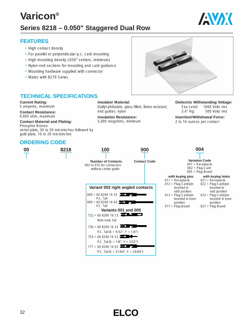
004
Variation Code001 = Receptacle002 = Plug-Card005 = Plug-Board
Varicon®
Series 8218 – 0.050" Staggered Dual Row
FEATURES• High contact density• For parallel or perpendicular p.c. card mounting• High mounting density (.050" centers, minimum)• Nylon end sections for mounting and card guidance• Mounting hardware supplied with connector• Mates with 8219 Series
TECHNICAL SPECIFICATIONS
ORDERING CODE00 8218 100 000
Contact Code
Current Rating:5 amperes, maximum
Contact Resistance:0.005 ohm, maximumContact Material and Plating:Phosphor Bronzenickel plate, 30 to 50 microinches followed by gold plate, 10 to 20 microinches
Insulator Material:Diallyl phthalate, glass-filled, flame resistant, end guides: nylon
Insulation Resistance:5,000 megohms, minimum
Dielectric Withstanding Voltage:Sea Level: 1000 Volts rms3.4" Hg: 500 Volts rms
Insertion/Withdrawal Force:2 to 16 ounces per contact
Variant 002 right angled contacts
000 = 60 8200 16 33P.C. Tail
000 = 60 8200 16 63P.C. Tail
Variants 001 and 005 722 = 60 8200 16 13
Wire Hole Tail
736 = 60 8200 16 33
P.C. Tail (X = 9/32", Y = 1/4")
753 = 60 8200 16 53
P.C. Tail (X = 1/8", Y = 3/32")
771 = 60 8200 16 63
P.C. Tail (X = 31/64", Y = 29/64")
with keying pins011 = Receptacle012 = Plug-Card/pin
inserted in odd position
013 = Plug-Card/pin inserted in even position
017 = Plug-Board
with keying holes021 = Receptacle022 = Plug-Card/pin
inserted in odd position
023 = Plug-Card/pin inserted in even position
027 = Plug-Board
Number of Contacts002 to 076 for connectors
without center guide

33ELCOELCO
Varicon®
Series 8218 – 0.050" Staggered Dual Row
RECEPTACLE 001 – MATES WITH PLUGS 002 AND 005
MOUNTING LAYOUT
DIMENSIONS:
Variation 001 and 005 Variation 002
Receptacle Variation 001 Plug Variation 002 Plug Variation 005
Determine polarization pin location from views.P = Specify location by contact # where polarizing pin must be inserted.H = Specify location by contact # where contact must be omitted for mating.
Typical Example: 00-8218-024-721-001-P-17 (polarizing pin mtd. in position 17)00-8218-024-721-005-H-17 (polarizing hole is in position 17)
POLARIZATIONKeying Ordering No.60-8218-4715-00-148
Minimum Center to CenterSpacing for Adjustment Plugs
A B C D E
(No. of contacts x “A” dimension “A” dimension “A” dimension “A” dimension0.050") - 0.050" + 0.300" + 0.440" + 0.550" + 0.690"
(inches)

34 ELCOELCO
001 = ReceptacleWithout
002 = Plug, perpendicular board mountingKeying005 = Plug, parallel board mounting
CodeContact Type
“X”No. Dim.722 Wire hole tail .187721 P. C. solder tail .250736 P. C. solder tail .281737 P. C. solder tail .562753 P. C. solder tail .125771 P. C. solder tail .484
Varicon®
Series 8219 – 0.050" Staggered Dual Row
FEATURES• For p.c. card-to-card applications• High contact density• Low withdrawal force contacts• Rugged, color coded end guides• Parallel or perpendicular p.c. board mounting• Mates with Series 8218
TECHNICAL SPECIFICATIONS
ORDERING CODE00 8219 042
Number of Contacts018, 030, 036, 042, 054, 072
722
Contact Code(see below)
001
Variation Code
Current Rating:5 amperes, maximum
Contact Resistance:6 milliohms, maximumContact Material and Plating:Phosphor BronzeGold, 10 microinches minimum, over nickel, 50 to 100 microinches
Insulator Material:Diallyl phthalate, glass-filled, flame resist-ant per MIL-M-14F, Type SDGF.
Guidance Hardware:Left hand guides: Metal, gold colorRight hand guides: Metal, silver color
Insulation Resistance:5,000 megohms, minimum
Dielectric Withstanding Voltage:Sea Level: 1000 Volts rms3.4" Hg: 500 Volts rms
Insertion/Withdrawal Force:2 to 8 ounces per contact
Conforms to Military Specifications:MIL-C-55302 QPL Approved
For Variation = 001
CodeContact TypeNo.
000 P. C. solder tails formed722 Wire hole tail unformed
For Variation = 002
CodeContact Type
“Y”No. Dim.722 Wire hole tail .157721 P. C. solder tail .219736 P. C. solder tail .250737 P. C. solder tail .531753 P. C. solder tail .093771 P. C. solder tail .453
For Variation = 005
NOTE: Connector is supplied with mounting screws or eyelets, as applicable(see drawings).
Contact Factory for Special Variations.
When Keying is ordered with part number, the Key is installed at the factory.
POLARIZING SYSTEM

35ELCOELCO
Varicon®
Series 8219 – 0.050" Staggered Dual Row
NumberRef. Ref.
of A B CD
E F GKContacts
18 17 .850 (0.033) 1.150 (0.045) 1.290 (0.051) 1.400 (0.055) 1.540 (0.061) .964 (0.038) 1.300 (0.051)30 29 1.450 (0.057) 1.750 (0.069) 1.890 (0.075) 2.000 (0.079) 2.140 (0.084) 1.564 (0.061) 1.900 (0.075)36 35 1.750 (0.069) 2.050 (0.080) 2.190 (0.086) 2.300 (0.091) 2.440 (0.096) 1.864 (0.073) 2.220 (0.087)42 41 2.050 (0.080) 2.350 (0.093) 2.490 (0.098) 2.600 (0.102) 2.740 (0.108) 2.164 (0.085) 2.500 (0.098)54 53 2.650 (0.104) 2.950 (0.116) 3.090 (0.122) 3.200 (0.126) 3.340 (0.131) 2.764 (0.109) 3.100 (0.122)72 71 3.550 (0.140) 3.850 (0.152) 3.990 (0.157) 4.100 (0.161) 4.240 (0.167) 3.664 (0.144) 4.000 (0.157)
DIMENSIONS: millimeters (inches)
RECEPTACLE 001 MATES WITH PLUGS 002 AND 005
MOUNTING LAYOUTS
*When used in metal panel with Code Contact 722 cut out diam. Is .210".

36 ELCOELCO
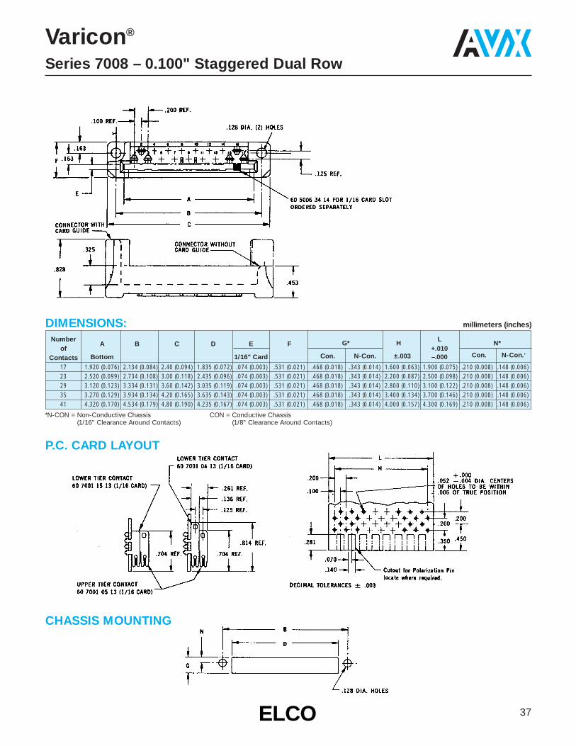
Varicon®
Series 7008 – 0.100" Staggered Dual Row
FEATURES• Available with or without card guides• Many sizes• Wide range of contact terminations• For 1⁄16" thick PCB• Polarization insert• Mates with Series 7000 and 7022 Plugs
TECHNICAL SPECIFICATIONS
00 7008 017
Number of Contacts017, 023, 029, 035, 041
146
Contact CodeSee table.
001
Variation Code
Current Rating:10 amperes
Contact Resistance:6 milliohms, maximumContact Material and Plating:Phosphor Bronze per QQ-B-750,Composition A.Gold, 10 microinches minimum, over nickel, 30 to 100 microinches
Insulator Material:Diallyl phthalate, glass-filled, flame resistant, per MIL-M-14F, Type SDGF.
Insulation Resistance:25,000 megohms, minimum
Dielectric Withstanding Voltage:Sea Level: 2000 Volts rms3.4" Hg: 675 Volts rms
Insertion/Withdrawal Force:2 to 16 ounces per contact
Conforms to Military Specifications:MIL-E-5400, MIL-E-8189, MIL-T-21200MIL-E-19600 (BuWeps), Paragraph 3.5.5.
141 = 60 7001 06 33P.C. Termination for 1/8" Card
146 = 60 7001 13 13.078" Base Taper Tab
156 = 60 7001 18 13
Wire wrapping (.026 x .062 x .600")
163 = 60 7001 19 13
.098" Base Taper Tab w/Wire Hole
165 = 60 7001 20 13
Forked Tail Solder Termination for Bus Line Connection
(.056 x .125" Slot)
166 = 60 7001 20 23
Dual Solder Termination for 2 Wires or Bus Line
(.056 x .125" Slot)
189 = 60 7004 02 13
Conventional Solder Termination for 3 Wires
AvailabilityConnector No. of Contacts
Description 17 23 29 35 41With Guides – for 1/16" Card X X X X X
Without Guides – for 1/16" /Card X X X X X
Card Card CodeSlot Guides1/16" Yes 001
No 002
ORDERING CODE
37ELCOELCO
Varicon®
Series 7008 – 0.100" Staggered Dual Row
Number G* H L N*of
A B C D E F+.010
Contacts Bottom 1/16" Card Con. N-Con. ±.003 –.000 Con. N-Con..
17 1.920 (0.076) 2.134 (0.084) 2.40 (0.094) 1.835 (0.072) .074 (0.003) .531 (0.021) .468 (0.018) .343 (0.014) 1.600 (0.063) 1.900 (0.075) .210 (0.008) .148 (0.006)23 2.520 (0.099) 2.734 (0.108) 3.00 (0.118) 2.435 (0.096) .074 (0.003) .531 (0.021) .468 (0.018) .343 (0.014) 2.200 (0.087) 2.500 (0.098) .210 (0.008) .148 (0.006)29 3.120 (0.123) 3.334 (0.131) 3.60 (0.142) 3.035 (0.119) .074 (0.003) .531 (0.021) .468 (0.018) .343 (0.014) 2.800 (0.110) 3.100 (0.122) .210 (0.008) .148 (0.006)35 3.270 (0.129) 3.934 (0.134) 4.20 (0.165) 3.635 (0.143) .074 (0.003) .531 (0.021) .468 (0.018) .343 (0.014) 3.400 (0.134) 3.700 (0.146) .210 (0.008) .148 (0.006)41 4.320 (0.170) 4.534 (0.179) 4.80 (0.190) 4.235 (0.167) .074 (0.003) .531 (0.021) .468 (0.018) .343 (0.014) 4.000 (0.157) 4.300 (0.169) .210 (0.008) .148 (0.006)
DIMENSIONS: millimeters (inches)
*N-CON = Non-Conductive Chassis (1/16" Clearance Around Contacts)
CON = Conductive Chassis(1/8" Clearance Around Contacts)
P.C. CARD LAYOUT
CHASSIS MOUNTING

38 ELCOELCO
Varicon®
Series 7022 – 0.100" Staggered Dual Row
FEATURES• Insulator rigidity reduces p.c. card warp• Insulator maintains exact spacing between contacts• Reduces cost of card punching operation (fewer holes)• Reduces cost of contact staking operation (one
operation instead of two)• Reduces assembly time (no plastic strip to remove)• For 1⁄16" or 3⁄32" p.c. card• Mates with Series 7000 Receptacleswith or without
card guides
TECHNICAL SPECIFICATIONS
ORDERING CODE
MOUNTING LAYOUT
00 7022 023
Number of Contacts017, 023, 029, 035, 041
For Series 7008 receptacle
000 001
Current Rating:10 amperes
Contact Resistance:6 milliohms, maximumContact Material and Plating:Phosphor Bronze per QQ-B-750,Composition A.Gold, 10 microinches minimum, over nickel, 30 to 100 microinches
Insulator Material:Diallyl phthalate, glass-filled, per MIL-M-14F, Type SDGF.
Variation 001/002Thermoplastic Polycarbonate Variation 003
Insulation Resistance:25,000 megohms, minimum
Dielectric Withstanding Voltage:Sea Level: 2000 Volts rms3.4" Hg: 675 Volts rms
Insertion/Withdrawal Force:2 to 16 ounces per contact
Conforms to Military Specifications:MIL-E-5400, MIL-E-8189, MIL-T-21200MIL-E-19600 (BuWeps), Paragraph 3.5.5.
Variation Code001 = 1/16" Module Card Thickness002 = 3/32" Module Card Thickness003 = 1/16" Module Card Thickness
60 7001 2913 for 1/16" Card 60 7001 2813 for 1/16" Card60 7001 2923 for 3/32" Card6 560 7001 2823 for 3/32" Card
39ELCOELCO
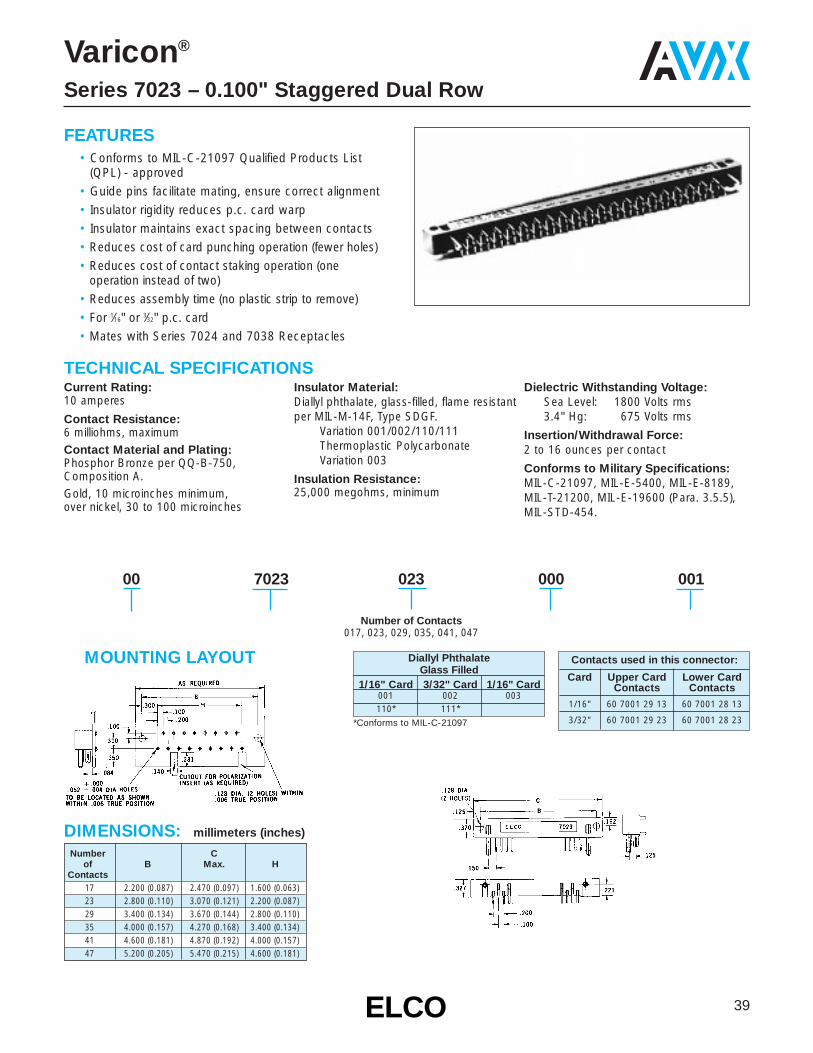
Number Cof B Max. H
Contacts17 2.200 (0.087) 2.470 (0.097) 1.600 (0.063)23 2.800 (0.110) 3.070 (0.121) 2.200 (0.087)29 3.400 (0.134) 3.670 (0.144) 2.800 (0.110)35 4.000 (0.157) 4.270 (0.168) 3.400 (0.134)41 4.600 (0.181) 4.870 (0.192) 4.000 (0.157)47 5.200 (0.205) 5.470 (0.215) 4.600 (0.181)
Contacts used in this connector:
Card Upper Card Lower CardContacts Contacts
1/16" 60 7001 29 13 60 7001 28 13
3/32" 60 7001 29 23 60 7001 28 23
Varicon®
Series 7023 – 0.100" Staggered Dual Row
FEATURES• Conforms to MIL-C-21097 Qualified Products List
(QPL) - approved• Guide pins facilitate mating, ensure correct alignment• Insulator rigidity reduces p.c. card warp• Insulator maintains exact spacing between contacts• Reduces cost of card punching operation (fewer holes)• Reduces cost of contact staking operation (one
operation instead of two)• Reduces assembly time (no plastic strip to remove)• For 1⁄16" or 3⁄32" p.c. card• Mates with Series 7024 and 7038 Receptacles
TECHNICAL SPECIFICATIONS
MOUNTING LAYOUT
00 7023 023
Number of Contacts017, 023, 029, 035, 041, 047
000 001
Current Rating:10 amperes
Contact Resistance:6 milliohms, maximumContact Material and Plating:Phosphor Bronze per QQ-B-750,Composition A.Gold, 10 microinches minimum, over nickel, 30 to 100 microinches
Insulator Material:Diallyl phthalate, glass-filled, flame resistantper MIL-M-14F, Type SDGF.
Variation 001/002/110/111Thermoplastic Polycarbonate Variation 003
Insulation Resistance:25,000 megohms, minimum
Dielectric Withstanding Voltage:Sea Level: 1800 Volts rms3.4" Hg: 675 Volts rms
Insertion/Withdrawal Force:2 to 16 ounces per contact
Conforms to Military Specifications:MIL-C-21097, MIL-E-5400, MIL-E-8189,MIL-T-21200, MIL-E-19600 (Para. 3.5.5),MIL-STD-454.
Diallyl PhthalateGlass Filled
1/16" Card 3/32" Card 1/16" Card001 002 003110* 111*
*Conforms to MIL-C-21097
DIMENSIONS: millimeters (inches)

40 ELCOELCO
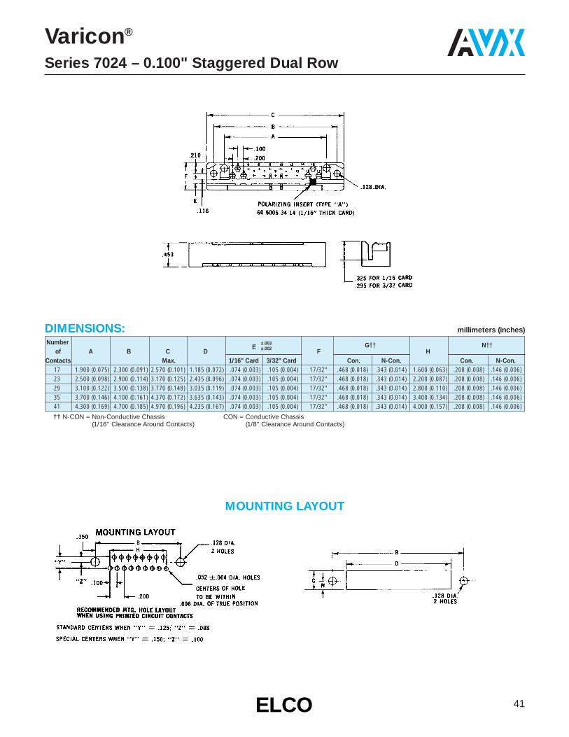
Varicon®
Series 7024 – 0.100" Staggered Dual Row
FEATURES• Conforms to MIL-C-21097 Qualified Products List (QPL)• Guide sockets facilitate mating, ensure correct alignment• Open-ended card slot; use with p.c. card of any width• Wide range of contact terminations• Many sizes available• For 1⁄16" or 3⁄32" p.c. card• Mates with Series 7023 Plug
TECHNICAL SPECIFICATIONS
ORDERING CODE00 7024 023
Number of Contacts017, 023, 029, 035, 041
163
Contact CodeSee table.
001
Variation Code001 = 1/16" Thick Card002 = 3/32" Thick Card110* = 1/16" Thick Card111* = 3/32" Thick Card
* For Conformance to MIL-C-21097B
Current Rating:10 amperes
Contact Resistance:6 milliohms, maximumContact Material and Plating:Phosphor Bronze per QQ-B-750,Composition A.Gold, 10 microinches minimum, over nickel, 30 to 100 microinches
Insulator Material:Diallyl phthalate, glass-filled,flame resistant, per MIL-M-14F, Type SDGF.
Insulation Resistance:25,000 megohms, minimumDielectric Withstanding Voltage:
Sea Level: 1800 Volts rms3.4" Hg: 675 Volts rms
Insertion/Withdrawal Force:2 to 16 ounces per contact
Conforms to Military Specifications:MIL-C-21097, MIL-E-5400, MIL-E-8189,MIL-T-21200, MIL-E-19600 (Para. 3.5.5),MIL-STD-454.
141 = 60 7001 06 33P.C. Termination for 1/8" Card
146 = 60 7001 13 13.078" Base Taper Tab
156 = 60 7001 18 13
Wire wrapping (.026 x .062 x .600")
163 = 60 7001 19 13
.098" Base Taper Tab w/Wire Hole
165 = 60 7001 20 13
Forked Tail Solder Termination for Bus Line Connection
(.056 x .125" Slot)
166 = 60 7001 20 23
Dual Solder Termination for 2 Wires or Bus Line
(.056 x .125" Slot)
189 = 60 7004 02 13
Conventional Solder Termination for 3 Wires
AvailabilityConnector No. of Contacts
Description 17 23 29 35 41For 1/16" Card X X X X X
For 3/32" Card X X X X X
41ELCOELCO
Number ±.003 G†† N††of A B C D
E ±.002 F HContacts Max. 1/16" Card 3/32" Card Con. N-Con. Con. N-Con.
17 1.900 (0.075) 2.300 (0.091) 2.570 (0.101) 1.185 (0.072) .074 (0.003) .105 (0.004) 17/32" .468 (0.018) .343 (0.014) 1.600 (0.063) .208 (0.008) .146 (0.006)23 2.500 (0.098) 2.900 (0.114) 3.170 (0.125) 2.435 (0.096) .074 (0.003) .105 (0.004) 17/32" .468 (0.018) .343 (0.014) 2.200 (0.087) .208 (0.008) .146 (0.006)29 3.100 (0.122) 3.500 (0.138) 3.770 (0.148) 3.035 (0.119) .074 (0.003) .105 (0.004) 17/32" .468 (0.018) .343 (0.014) 2.800 (0.110) .208 (0.008) .146 (0.006)35 3.700 (0.146) 4.100 (0.161) 4.370 (0.172) 3.635 (0.143) .074 (0.003) .105 (0.004) 17/32" .468 (0.018) .343 (0.014) 3.400 (0.134) .208 (0.008) .146 (0.006)41 4.300 (0.169) 4.700 (0.185) 4.970 (0.196) 4.235 (0.167) .074 (0.003) .105 (0.004) 17/32" .468 (0.018) .343 (0.014) 4.000 (0.157) .208 (0.008) .146 (0.006)
Varicon®
Series 7024 – 0.100" Staggered Dual Row
MOUNTING LAYOUT
DIMENSIONS: millimeters (inches)
†† N-CON = Non-Conductive Chassis (1/16" Clearance Around Contacts)
CON = Conductive Chassis(1/8" Clearance Around Contacts)
42 ELCOELCO
Varicon®
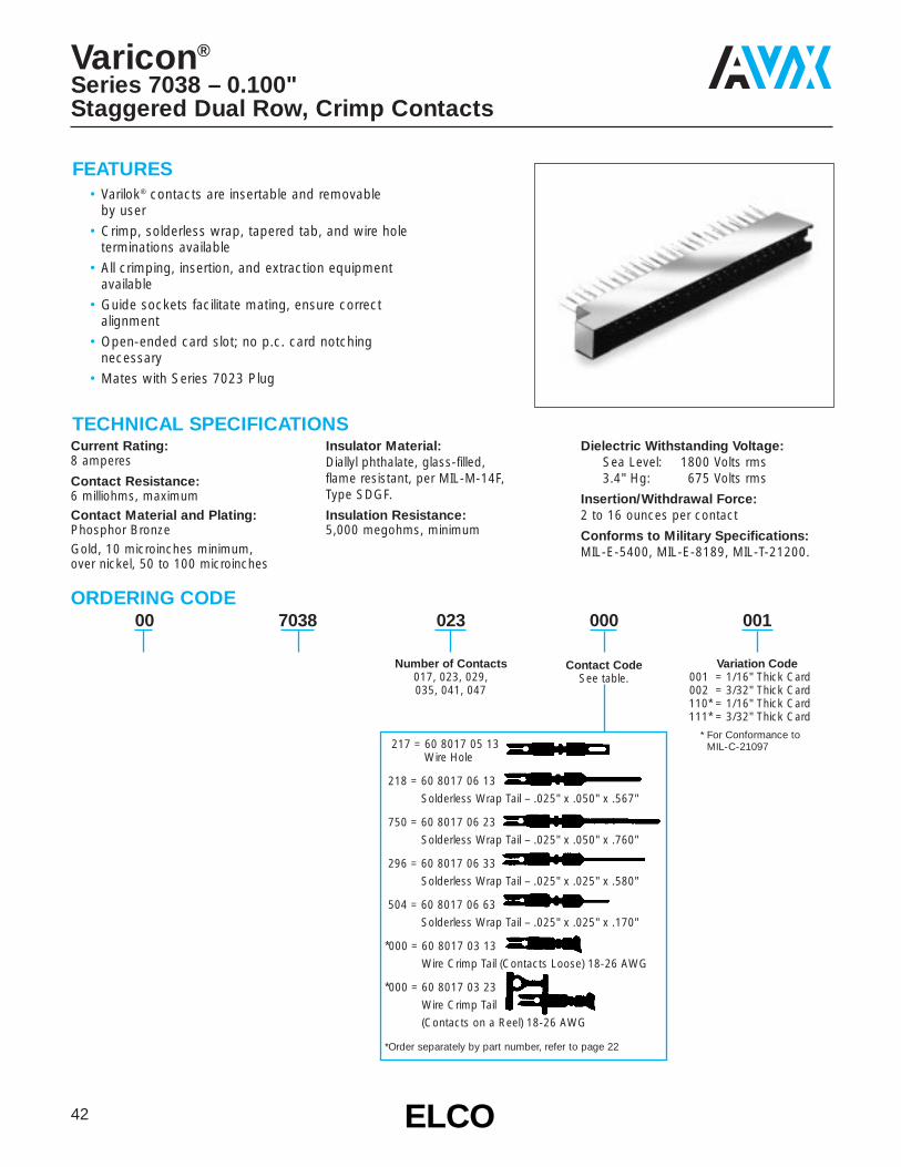
Series 7038 – 0.100"Staggered Dual Row, Crimp Contacts
FEATURES• Varilok® contacts are insertable and removable
by user• Crimp, solderless wrap, tapered tab, and wire hole
terminations available• All crimping, insertion, and extraction equipment
available• Guide sockets facilitate mating, ensure correct
alignment• Open-ended card slot; no p.c. card notching
necessary• Mates with Series 7023 Plug
TECHNICAL SPECIFICATIONS
ORDERING CODE00 7038 023
Number of Contacts017, 023, 029, 035, 041, 047
000
Contact CodeSee table.
001
Variation Code001 = 1/16" Thick Card002 = 3/32" Thick Card110* = 1/16" Thick Card111* = 3/32" Thick Card
* For Conformance to MIL-C-21097
Current Rating:8 amperes
Contact Resistance:6 milliohms, maximumContact Material and Plating:Phosphor BronzeGold, 10 microinches minimum, over nickel, 50 to 100 microinches
Insulator Material:Diallyl phthalate, glass-filled, flame resistant, per MIL-M-14F, Type SDGF.
Insulation Resistance:5,000 megohms, minimum
Dielectric Withstanding Voltage:Sea Level: 1800 Volts rms3.4" Hg: 675 Volts rms
Insertion/Withdrawal Force:2 to 16 ounces per contact
Conforms to Military Specifications:MIL-E-5400, MIL-E-8189, MIL-T-21200.
217 = 60 8017 05 13Wire Hole
218 = 60 8017 06 13
Solderless Wrap Tail – .025" x .050" x .567"
750 = 60 8017 06 23
Solderless Wrap Tail – .025" x .050" x .760"
296 = 60 8017 06 33
Solderless Wrap Tail – .025" x .025" x .580"
504 = 60 8017 06 63
Solderless Wrap Tail – .025" x .025" x .170"
*000 = 60 8017 03 13
Wire Crimp Tail (Contacts Loose) 18-26 AWG
*000 = 60 8017 03 23
Wire Crimp Tail
(Contacts on a Reel) 18-26 AWG
*Order separately by part number, refer to page 22

43ELCOELCO
Numberof A B C D E F G J
Contacts Max. 1/16" Card 3/32" Card17 1.900 (0.075) 2.300 (0.091) 2.570 (0.101) 1.890 (0.075) .074 (0.003) .105 (0.004) 17/32" .571 (0.022) 1.850 (0.073)23 2.500 (0.099) 2.900 (0.114) 3.170 (0.125) 2.490 (0.098) .074 (0.003) .105 (0.004) 17/32" .571 (0.022) 2.450 (0.096)29 3.100 (0.122) 3.500 (0.138) 3.770 (0.148) 3.090 (0.121) .074 (0.003) .105 (0.004) 17/32" .571 (0.022) 3.050 (0.120)35 3.700 (0.146) 4.100 (0.161) 4.370 (0.172) 3.690 (0.145) .074 (0.003) .105 (0.004) 17/32" .571 (0.022) 3.650 (0.144)41 4.300 (0.169) 4.700 (0.185) 4.970 (0.196) 4.290 (0.169) .074 (0.003) .105 (0.004) 17/32" .571 (0.022) 4.250 (0.167)47 4.900 (0.193) 5.300 (0.209) 5.570 (0.219) 4.890 (0.193) .074 (0.003) .105 (0.004) 17/32" .634 (0.025) 4.850 (0.191)
DIMENSIONS: millimeters (inches)
Varicon®
Series 7038 – 0.100"Staggered Dual Row, Crimp Contacts
MOUNTING LAYOUT

FEATURES• Plug consists only of contacts staked and
soldered to p.c. card; no other insulator needed• For 1⁄16" thick p.c. cards• Contacts supplied imbedded in vinyl strips,
correctly spaced and ready for insertion and staking into p.c. card
• Mates with Series 7000 Receptacles
TECHNICAL SPECIFICATIONS
ORDERING CODE02 000
Number of Contacts1 (001) to 60 (060)
147
Contact CodeSee table.
5
ContactPattern
200
ContactPitch
Current Rating:10 amperes
Contact Resistance:6 milliohms, maximum
Contact Material and Plating:Phosphor Bronze per QQ-B-750,Composition A.†Gold, 10 microinches minimum, over nickel, 30 to 100 microinches
Insertion/Withdrawal Force:2 to 16 ounces per contact
Conforms to Military Specifications:MIL-E-5400, MIL-E-8189, MIL-T-21200MIL-E-19600 (BuWeps), Paragraph 3.5.5.†ELCO Standard Plating shown. Other
plating may be supplied on request.
For loose contacts, order by individual part numbers tabulated on page 51.
44 ELCOELCO
Varicon®
Series 7000 – Contact Strip
Contact ContactContact Code Part No. Silhouette
1/16" Thick Card
Lower Tier 147 60 7001 15 13
Lower Tierwith Wire 135 60 7001 04 13HoleUpper Tierwith Wire 137 60 7001 05 13HoleLower Tierwith Wire 144 60 7001 11 13Hole
Upper Tier and Lower TierContacts on Separate Strips
000
45ELCOELCO
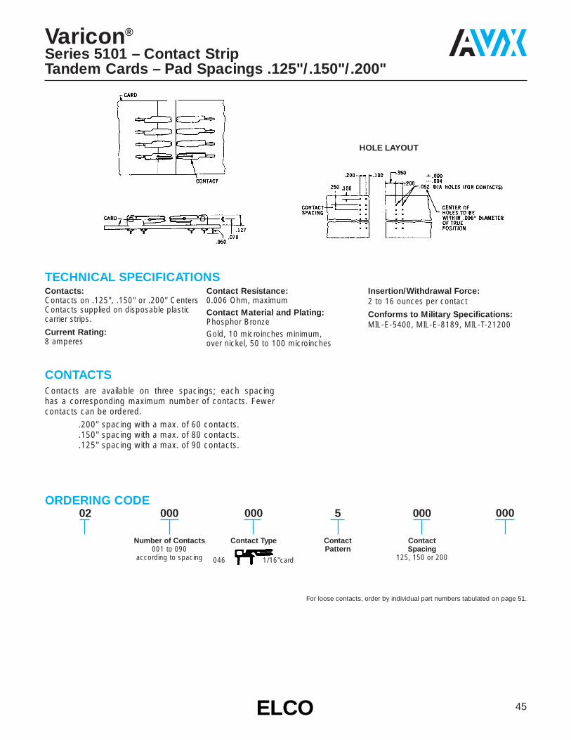
Varicon®
Series 5101 – Contact StripTandem Cards – Pad Spacings .125"/.150"/.200"
TECHNICAL SPECIFICATIONSContacts:Contacts on .125", .150" or .200" CentersContacts supplied on disposable plasticcarrier strips.
Current Rating:8 amperes
Contact Resistance:0.006 Ohm, maximumContact Material and Plating:Phosphor BronzeGold, 10 microinches minimum, over nickel, 50 to 100 microinches
Insertion/Withdrawal Force:2 to 16 ounces per contact
Conforms to Military Specifications:MIL-E-5400, MIL-E-8189, MIL-T-21200
ORDERING CODE
HOLE LAYOUT
02 000
Number of Contacts001 to 090
according to spacing
000
Contact Type
046 1/16"card
5
Contact
000
ContactSpacing
125, 150 or 200
CONTACTSContacts are available on three spacings; each spacing has a corresponding maximum number of contacts. Fewercontacts can be ordered.
.200” spacing with a max. of 60 contacts.
.150" spacing with a max. of 80 contacts.
.125" spacing with a max. of 90 contacts.
For loose contacts, order by individual part numbers tabulated on page 51.
000
Pattern
02 000
Number of Contacts1 (001) to 63 (063)
000
Contact Type
5 200
Lower Tier:
135 1/16" card
144 1/16" card
147 1/16" card
228 1/16" card
Upper Tier:
137 1/16" card
02 000
Number of Contacts1 (001) to 125
000
Contact Type
1 200
46 ELCOELCO
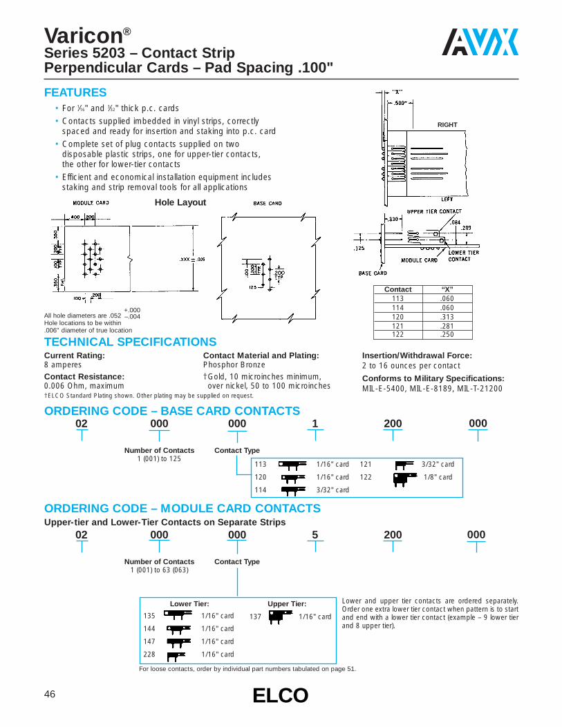
Varicon®
Series 5203 – Contact StripPerpendicular Cards – Pad Spacing .100"
TECHNICAL SPECIFICATIONSCurrent Rating:8 amperesContact Resistance:0.006 Ohm, maximum
Contact Material and Plating:Phosphor Bronze†Gold, 10 microinches minimum, over nickel, 50 to 100 microinches
Insertion/Withdrawal Force:2 to 16 ounces per contact
Conforms to Military Specifications:MIL-E-5400, MIL-E-8189, MIL-T-21200
ORDERING CODE – BASE CARD CONTACTS
ORDERING CODE – MODULE CARD CONTACTSUpper-tier and Lower-Tier Contacts on Separate Strips
FEATURES• For 1⁄16" and 3⁄32" thick p.c. cards• Contacts supplied imbedded in vinyl strips, correctly
spaced and ready for insertion and staking into p.c. card• Complete set of plug contacts supplied on two
disposable plastic strips, one for upper-tier contacts, the other for lower-tier contacts
• Efficient and economical installation equipment includesstaking and strip removal tools for all applications
†ELCO Standard Plating shown. Other plating may be supplied on request.
113 1/16" card
120 1/16" card
114 3/32" card
121 3/32" card
122 1/8" card
Lower and upper tier contacts are ordered separately.Order one extra lower tier contact when pattern is to startand end with a lower tier contact (example – 9 lower tierand 8 upper tier).
Contact “X”113 .060114 .060120 .313121 .281122 .250
All hole diameters are .052+.000
Hole locations to be within–.004
.006" diameter of true location
Hole Layout
RIGHT
For loose contacts, order by individual part numbers tabulated on page 51.
000
000
47ELCOELCO
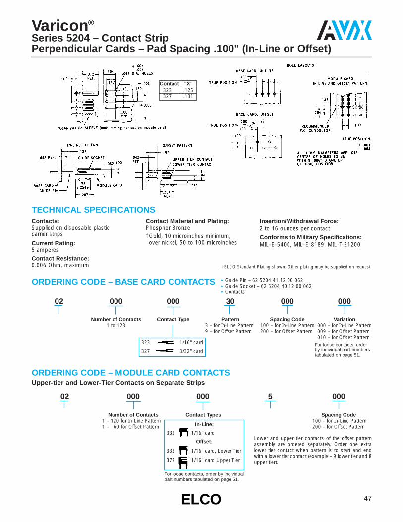
02 000
Number of Contacts1 – 120 for In-Line Pattern1 – 60 for Offset Pattern
000
Contact Types
5 000
Spacing Code100 – for In-Line Pattern200 – for Offset PatternIn-Line:
332 1/16" card
Offset:
332 1/16" card, Lower Tier
372 1/16" card Upper Tier
02 000
Number of Contacts1 to 123
000
Contact Type
30
Pattern3 – for In-Line Pattern9 – for Offset Pattern
000
Spacing Code100 – for In-Line Pattern200 – for Offset Pattern
000
Variation000 – for In-Line Pattern009 – for Offset Pattern010 – for Offset Pattern
Varicon®
Series 5204 – Contact StripPerpendicular Cards – Pad Spacing .100" (In-Line or Offset)
TECHNICAL SPECIFICATIONSContacts:Supplied on disposable plastic carrier strips
Current Rating:5 amperesContact Resistance:0.006 Ohm, maximum
Contact Material and Plating:Phosphor Bronze†Gold, 10 microinches minimum, over nickel, 50 to 100 microinches
Insertion/Withdrawal Force:2 to 16 ounces per contact
Conforms to Military Specifications:MIL-E-5400, MIL-E-8189, MIL-T-21200
ORDERING CODE – BASE CARD CONTACTS
ORDERING CODE – MODULE CARD CONTACTSUpper-tier and Lower-Tier Contacts on Separate Strips
†ELCO Standard Plating shown. Other plating may be supplied on request.
323 1/16" card
327 3/32" card
Lower and upper tier contacts of the offset patternassembly are ordered separately. Order one extralower tier contact when pattern is to start and endwith a lower tier contact (example – 9 lower tier and 8upper tier).
Contact “X”323 .125327 .131
For loose contacts, orderby individual part numberstabulated on page 51.
• Guide Pin – 62 5204 41 12 00 062• Guide Socket – 62 5204 40 12 00 062• Contacts
For loose contacts, order by individual part numbers tabulated on page 51.

48 ELCOELCO
Varicon®
Series 5208 – Contact StripPerpendicular Cards – Pad Spacing .200"
TECHNICAL SPECIFICATIONSContacts:Supplied on disposable plastic carrier strips.
Current Rating:8 amperes
Contact Resistance:0.006 Ohm, maximumContact Material and Plating:Phosphor BronzeGold, 10 microinches minimum, over nickel, 50 to 100 microinches
Insertion/Withdrawal Force:2 to 16 ounces per contact
Conforms to Military Specifications:MIL-E-5400, MIL-E-8189, MIL-T-21200
02 000
Number of Contacts1 to 63
000
Contact Type
3 200
For loose contacts, order by individualpart numbers tabulated on page 51.
Contact “X”113 .060114 .060115 .060120 .313121 .281122 .250
All hole diameters are .052+.000
Hole locations to be within–.004
.006" diameter of true location
113 1/16" card
120 1/16" card
114 3/32" card
121 3/32" card
122 1/8" card
02 000
Number of Contacts1 to 63
000
Contact Type
5 200
In-Line:
013 1/16" card
014 3/32" card
ORDERING CODE – BASE CARD CONTACTS
ORDERING CODE – MODULE CARD CONTACTS
• Card Guides: See top drawing for appropriate part number• Contacts
HOLE LAYOUTMODULE CARD

49ELCOELCO
For loose contacts, order by individualpart numbers tabulated on page 51.
113 1/16" card
120 1/16" card
114 3/32" card
121 3/32" card
122 1/8" card
02 000
Number of Contacts001 to 090
according to spacing
000
Contact Type
6 000
ContactSpacing
125, 150 or 200
Varicon®
Series 5301 – Contact StripParallel Cards – .438" Between Cards
TECHNICAL SPECIFICATIONSContacts:Supplied on disposable plastic carrier strips
Current Rating:8 amperesContact Resistance:0.006 Ohm, maximum
Contact Material and Plating:Phosphor BronzeGold, 10 microinches minimum, over nickel, 50 to 100 microinches
Insertion/Withdrawal Force:2 to 16 ounces per contact
Conforms to Military Specifications:MIL-E-5400, MIL-E-8189, MIL-T-21200
ORDERING CODE
Contact “X”113 .060114 .060120 .313121 .281122 .250
• Guide Pin – 62 5301 41 12 00 062 (1/16" card)62 5301 41 22 00 062 (3/32" card)
• Guide Socket – 62 5301 40 12 00 062 (1/16" card)62 5301 40 22 00 062 (3/32" card)
• Contacts – Contacts are available on four spacings;each spacing has a corresponding maximum number of contacts. Fewer contacts can be ordered.
.200" spacing with a max. of 60 contacts per strip
.150” spacing with a max. of 80 contacts per strip
.125" spacing with a max. of 90 contacts per strip

50 ELCOELCO
For loose contacts, order by individualpart numbers tabulated on page 51.
02 000
Number of Contacts001 to 120
000
Contact Type
6 100
Varicon®
Series 5304 – Contact StripParallel Cards – .213" Between Cards
TECHNICAL SPECIFICATIONSContacts:Contacts on .100 CentersSupplied on disposable plastic carrier strips
Current Rating:5 amperes
Contact Resistance:0.006 Ohm, maximumContact Material and Plating:Phosphor BronzeGold, 10 microinches minimum, over nickel, 50 to 100 microinches
Insertion/Withdrawal Force:2 to 16 ounces per contact
Conforms to Military Specifications:MIL-E-5400, MIL-E-8189, MIL-T-21200
ORDERING CODE
Contact “X”323 .125327 .131
• Guide Pin – 62 8202 40 12 00 062 (1/16" card)• Guide Socket – 62 5304 40 12 00 062 (1/16" card)
62 5301 40 12 00 062 (3/32" card)
323 1/16" card
327 3/32" card

51ELCOELCO
Varicon®
Installation Equipment
Contacts can be fastened to the p.c. card by staking or sol-dering and by the combination of staking and soldering.Contact retention tests indicate that it requires 25 lbs. of force to pull out a soldered contact, 45 lbs. for a stakedcontact and 65 lbs. for a staked and soldered contact.Staking is accomplished with a knife-like tool which shaves a portion of the contact leg against the p.c. card. Elco can furnish the necessary staking equipment for both highquantity production and laboratory experimentation.Once the contacts are fastened to the board it is generallynecessary to remove the plastic carrier strip. The plasticshould be softened prior to removal to avoid the possibility of inadvertently bending the contacts.
Contacts supplied embedded in disposable plastic strips, correctly spaced and ready for insertion and
staking into p.c. card.
Hand staker 06 1856 01 is designed for use as a multi-purpose laboratory tool. This versatile tool enables you tostake most contacts presently available. The hand stakerand replacement staking punches are available from stock.
SPECIFICATIONS• Rating – 1/4 ton capacity• Ram Dimensions – 1⁄2" x 1⁄2" x 21⁄2"• Ram Stroke – 13⁄16"• Height of Opening – under punch 1"• Throat depth from center of ram – 1"• Working Surface – 2" x 27⁄8"• Weight – 3 lbs.• Size – 4" wide x 5" deep x 4" high
Laboratory Tool for Contact Staking Model 06 1856 01(Staking Punch Not Included)
HAND STAKER MODEL NO. 06 1856 01
ContactLoose Contact Staking PunchCodePart Number Part NumberNumber
013 60 5001 19 13 00 339 66 1280 02014 60 5001 19 23 00 339 66 1280 02046 62 5101 06 43 00 339 66 1280 02113 62 5201 02 13 00 339 66 1280 02114 62 5201 02 23 00 339 66 1280 02120 62 5201 05 13 00 339 66 1280 19121 62 5201 05 23 00 339 66 1280 19122 62 5201 05 33 00 339 66 1280 19135 60 7001 04 13 00 339 66 1280 02137 60 7001 05 13 00 339 66 1280 02144 60 7001 11 13 00 339 66 1280 02147 60 7001 15 13 00 339 66 1280 02228 60 7001 15 93 00 339 66 1280 02332 60 8240 03 13 00 339 66 1280 17371 60 8240 26 13 00 339 66 1280 17372 60 8240 26 23 00 339 66 1280 17323 60 8240 02 13 00 339 66 1280 17327 60 8240 02 43 00 339 66 1280 26
ORDERING CODE FOR LOOSE CONTACTS
Card GuideNumber
62 5204 41 12 00 06262 5204 40 12 00 06262 8202 40 12 00 06262 8202 40 02 00 06262 5304 40 12 00 06262 5304 40 02 00 06262 5301 41 12 00 06262 5301 41 22 00 06262 5301 41 32 00 06262 5301 40 12 00 06262 5301 40 22 00 06262 5301 40 32 00 062
ORDERING CODE FOR CARD GUIDE STAKING EQUIPMENT
52 ELCOELCO
Internet/FAX/CD Rom/SoftwareNeed Additional Information on AVX Products
AVX Products
NOTICE: Specifications are subject to change without notice. Contact your nearest AVX Sales Office for the latest specifications. Allstatements, information and data given herein are believed to be accurate and reliable, but are presented without guarantee, warranty, orresponsibility of any kind, expressed or implied. Statements or suggestions concerning possible use of our products are made withoutrepresentation or warranty that any such use is free of patent infringement and are not recommendations to infringe any patent. The usershould not assume that all safety measures are indicated or that other measures may not be required. Specifications are typical and may notapply to all applications.
CONNECTORSAutomotive Connectors
Board to Board Connectors – SMT and Through-Hole
Card Edge
Custom Designed Connectors
Customized Backpanel, Racking and Harnessing Services
DIN 41612 Connectors
Insulation Displacement Connectors
I/O Connectors
Memory Card Headers and Sockets
MOBOTM, I/O, Board to Board and Battery Connectors
Press-fit Connectors
Torson, 1.27mm (.050") Board to Board Connectors
Wire to Board, Crimp or IDC
PASSIVESCapacitors
Multilayer CeramicTantalumMicrowaveGlassFilmPower FilmPower CeramicCeramic DiscTrimmers
ResistorsChipNetworks/ArraysPotentiometers
Timing DevicesResonatorsOscillatorsCrystal
FiltersEMIBulkSawDielectric
Thin FilmInductorsFusesCapacitors
Integrated PassiveComponentsLow Inductance Chip Arrays“Z” ChipsCapacitor ArraysDual Resonance Chips
Voltage Suppressor, Varistors and Thermistors
Acoustical Piezos
Ferrites
Internet –For more information visit us on theworldwide web athttp://www.avxcorp.com
FAX Back Service –Just dial 1-800-879-1613 and requestthe index for additional cataloginformation faxed to your FAX number.
CD ROM –Or get in touch with your AVXrepresentative for a CD Rom or copies ofthe catalogs and technical papers.
Software –Comprehensive capacitor applicationsoftware library which includes:
SpiCap (for MLC chip capacitors)SpiTan (for tantalum capacitors)SpiCalci (for power supply capacitors)SpiMic (for RF-Microwave capacitors)
S-VAR10M399-N
Contact:
USA
AVX Myrtle Beach, SCCorporate Offices
Tel: 843-448-9411FAX: 843-448-1943
AVX Northwest, WATel: 360-669-8746
FAX: 360-699-8751
AVX North Central, INTel: 317-848-7153
FAX: 317-844-9314
AVX Northeast, MATel: 508-485-8114
FAX: 508-485-8471
AVX Mid-Pacific, CATel: 408-436-5400
FAX: 408-437-1500
AVX Southwest, AZTel: 602-539-1496
FAX: 602-539-1501
AVX South Central, TXTel: 972-669-1223
FAX: 972-669-2090
AVX Southeast, NCTel: 919-878-6357
FAX: 919-878-6462
AVX CanadaTel: 905-564-8959
FAX: 905-564-9728
EUROPE
AVX Limited, EnglandEuropean Headquarters
Tel: ++44 (0)1252 770000FAX: ++44 (0)1252 770001
AVX S.A., FranceTel: ++33 (1) 69.18.46.00
FAX: ++33 (1) 69.28.73.87
AVX GmbH, Germany - AVXTel: ++49 (0) 8131 9004-0
FAX: ++49 (0) 8131 9004-44
AVX GmbH, Germany - ElcoTel: ++49 (0) 2741 2990
FAX: ++49 (0) 2741 299133
AVX srl, ItalyTel: ++390 (0)2 614571
FAX: ++390 (0)2 614 2576
AVX sro, Czech RepublicTel: ++420 (0)467 558340
FAX: ++420 (0)467 558345
ASIA-PACIFIC
AVX/Kyocera, SingaporeAsia-Pacific Headquarters
Tel: (65) 258-2833FAX: (65) 350-4880
AVX/Kyocera, Hong KongTel: (852) 2-363-3303
FAX: (852) 2-765-8185
AVX/Kyocera, KoreaTel: (82) 2-785-6504
FAX: (82) 2-784-5411
AVX/Kyocera, TaiwanTel: (886) 2-2516-7010
FAX: (886) 2-2506-9774
AVX/Kyocera, ChinaTel: (86) 21-6249-0314-16FAX: (86) 21-6249-0313
AVX/Kyocera, MalaysiaTel: (60) 4-228-1190
FAX: (60) 4-228-1196
Kyocera Elco, JapanTel: 045-943-2906/7FAX: 045-943-2910
Kyocera, JapanTel: (81) 75-593-4518
FAX: (81) 75-502-2705
A KYOCERA GROUP COMPANY
http://www.avxcorp.com
Elco – World Class Connections
Related Documents