Copyright © 2015 Vilnius Gediminas Technical University (VGTU) Press http://www.tandfonline.com/TAVI AVIATION ISSN 1648-7788 / eISSN 1822-4180 2015 Volume 19(3): 138–149 doi:10.3846/16487788.2015.1104847 A KINEMATIC APPROACH TO SEGMENTED-TRAJECTORY GENERATION FOR THE TOTAL LOSS OF THRUST EMERGENCY Kivanç A. AVRENLI 1 , Barry J. DEMPSEY 2 1 Syracuse University, 721 University Ave Syracuse NY, 13244 2 University of Illinois at Urbana-Champaign, 205 N Mathews Ave Urbana, IL 61801 E-mails: 1 [email protected] (corresponding author); 2 [email protected] Received 21 January 2015; accepted 28 January 2015 Kıvanç A. AVRENLİ, PhD Education: PhD in Civil (Transportation) Engineering, University of Illinois at Urbana-Champaign. M.S. in Statistics, University of Illinois at Urbana-Champaign. M.S. in Civil (Transportation) Engineering, Boğaziçi University Affiliation: Assistant Professor at Whitman School of Management, Syracuse University. Research interests: aircraſt operational safety, statistical modelling of aircraſt accidents and incidents. Barry J. DEMPSEY, PhD, P.E. Education: PhD in Civil (Transportation) Engineering, University of Illinois at Urbana- Champaign. M.S. in Civil (Transportation) Engineering, University of Illinois at Urbana- Champaign. Affiliation: Professor Emeritus of Civil Engineering at the University of Illinois at Urbana- Champaign. Awards: Recipient of the Federal Aviation Administration (FAA) Outstanding Service Award (1995). Recipient of the ASCE Robert Horonjeff Aviation Award (2009). Research interests: VFR lighted flyway marker system, aircraſt operation and safety. Previous affiliations: Former Director for the FAA Center of Excellence (COE) for Airport Pavement Research for 10 years. Served 3 years on a National Research Council Committee to develop the first Aviation Cooperative Research Program. Private pilot since October 1974 with thorough understanding of aircraſt operation and safety in Instrument Flight Rules (IFR) and Visual Flight Rules (VFR). Abstract. Contemporary twin-engine airliners are more vulnerable to total loss of thrust than yesterday’s three and four engine airliners, due to reduced engine redundancy. In the event of a total loss of thrust, flight crews have only one chance for landing, because the aircraſt cannot gain altitude. erefore, there is a pressing need to explore the idea of an engines-out landing trajectory optimization for commercial jets. A few past studies addressed this safety issue for general aviation aircraſt and fighter jets but not commercial jets, primarily because the essential aircraſt-specific aero- dynamic data are not publicly available. To fill in this gap, this study adopts a kinematic approach to aircraſt trajectory optimization. Unlike conventional trajectory optimization methods, the kinematic algorithm requires minimal amount of aircraſt-specific aerodynamic data that can be effortlessly collected in a full flight simulator. e paper describes the kinematic algorithm and applies it to a realistic bird strike scenario. Flight simulation tests are conducted in a full flight simulator to verify the accuracy of the algorithm. e results demonstrate that the algorithm can compute the optimum trajectory with a less than 3.0 percent error. Since the algorithm is accurate and computationally-undemand- ing, it is promising for real-world applications. Keywords: aircraſt, commercial, dual-engine failure, glide, jetliner, performance, power-off, powerless, en- gines-out, trajectory optimization, simulation, total loss of power.

Welcome message from author
This document is posted to help you gain knowledge. Please leave a comment to let me know what you think about it! Share it to your friends and learn new things together.
Transcript

Copyright © 2015 Vilnius Gediminas Technical University (VGTU) Press http://www.tandfonline.com/TAVI
AVIATIONISSN 1648-7788 / eISSN 1822-4180
2015 Volume 19(3): 138–149
doi:10.3846/16487788.2015.1104847
A KINEMATIC APPROACH TO SEGMENTED-TRAJECTORY GENERATION FOR THE TOTAL LOSS OF THRUST EMERGENCY
Kivanç A. AVRENLI1, Barry J. DEMPSEY2
1Syracuse University, 721 University Ave Syracuse NY, 132442University of Illinois at Urbana-Champaign, 205 N Mathews Ave Urbana, IL 61801
E-mails: [email protected] (corresponding author); [email protected]
Received 21 January 2015; accepted 28 January 2015
Kıvanç A. AVRENLİ, PhDEducation: PhD in Civil (Transportation) Engineering, University of Illinois at Urbana-Champaign. M.S. in Statistics, University of Illinois at Urbana-Champaign. M.S. in Civil (Transportation) Engineering, Boğaziçi UniversityAffiliation: Assistant Professor at Whitman School of Management, Syracuse University. Research interests: aircraft operational safety, statistical modelling of aircraft accidents and incidents.
Barry J. DEMPSEY, PhD, P.E.Education: PhD in Civil (Transportation) Engineering, University of Illinois at Urbana-Champaign. M.S. in Civil (Transportation) Engineering, University of Illinois at Urbana-Champaign.Affiliation: Professor Emeritus of Civil Engineering at the University of Illinois at Urbana-Champaign.Awards: Recipient of the Federal Aviation Administration (FAA) Outstanding Service Award (1995). Recipient of the ASCE Robert Horonjeff Aviation Award (2009).Research interests: VFR lighted flyway marker system, aircraft operation and safety. Previous affiliations: Former Director for the FAA Center of Excellence (COE) for Airport Pavement Research for 10 years. Served 3 years on a National Research Council Committee to develop the first Aviation Cooperative Research Program. Private pilot since October 1974 with thorough understanding of aircraft operation and safety in Instrument Flight Rules (IFR) and Visual Flight Rules (VFR).
Abstract. Contemporary twin-engine airliners are more vulnerable to total loss of thrust than yesterday’s three and four engine airliners, due to reduced engine redundancy. In the event of a total loss of thrust, flight crews have only one chance for landing, because the aircraft cannot gain altitude. Therefore, there is a pressing need to explore the idea of an engines-out landing trajectory optimization for commercial jets. A few past studies addressed this safety issue for general aviation aircraft and fighter jets but not commercial jets, primarily because the essential aircraft-specific aero-dynamic data are not publicly available. To fill in this gap, this study adopts a kinematic approach to aircraft trajectory optimization. Unlike conventional trajectory optimization methods, the kinematic algorithm requires minimal amount of aircraft-specific aerodynamic data that can be effortlessly collected in a full flight simulator. The paper describes the kinematic algorithm and applies it to a realistic bird strike scenario. Flight simulation tests are conducted in a full flight simulator to verify the accuracy of the algorithm. The results demonstrate that the algorithm can compute the optimum trajectory with a less than 3.0 percent error. Since the algorithm is accurate and computationally-undemand-ing, it is promising for real-world applications.
Keywords: aircraft, commercial, dual-engine failure, glide, jetliner, performance, power-off, powerless, en-gines-out, trajectory optimization, simulation, total loss of power.
Aviation, 2015, 19(3): 138–149 139
Notations
CV∆ Compressibility correction to convert calib-rated airspeed into equivalent airspeed.
jCX∆ Change in abscissa over circular segment j.
iLX∆ Change in abscissa over linear segment i.
,j jTX∆ Change in abscissa over the transition seg-ment connecting linear segment j to circular segment j.
, 1j jTX+
∆ Change in abscissa over the transition segment connecting linear segment j+1 to circular seg-ment j.
jCY∆ Change in ordinate over circular segment j.
iLY∆ Change in ordinate over linear segment i.
,j jTY∆ Change in ordinate over the transition seg-ment connecting linear segment j to circular segment j.
, 1j jTY+
∆ Change in ordinate over the transition segment connecting linear segment j+1 to circular seg-ment j.
jCZ∆ Altitude loss over circular segment j.
iLZ∆ Altitude loss over linear segment i.
,j jTZ∆ Altitude loss over the transition segment con-necting linear segment j to circular segment j.
, 1j jTZ+
∆ Altitude loss over the transition segment con-necting linear segment j+1 to circular segment j.
j∆θ Total change in aircraft heading (°) over circu-lar segment j and the adjacent transition seg-ments.
jC∆θ Change in aircraft heading (°) over circular segment j.
,j jT∆θ Change in aircraft heading (°) over the trans-ition segment connecting linear segment j to circular segment j.
, 1j jT +∆θ Change in aircraft heading (°) over the trans-
ition segment connecting linear segment j+1 to circular segment j.
, , ,v v v va b c d Coefficients of cubic spline.
jC Circular segment j.
,cot( )v ϕγ Engines-out glide ratio at calibrated air-speed v, and bank angle ϕ .
d Average relative difference for true airspeed between two consecutive iterations.
TouchdownE Elevation of the intended touchdown point.
jCE Average elevation of circular segment j.'
jCE Average elevation of circular segment j ex-pressed in feet.
g Gravitational acceleration.k Iteration number.
iL Linear segment i.
R2 Coefficient of determination for a statistical model.
1LS Length of linear segment i.
,j jT The transition segment connecting linear seg-ment j to circular segment j.
, 1j jT + The transition segment connecting linear seg-ment j+1 to circular segment j.
v Calibrated airspeed.
Tv True airspeed.
,T jν Average true airspeed over circular segment j.
0X Abscissa of the aircraft position at the begin-ning of the engines-out landing maneuver.
TouchdownX Abscissa of the intended touchdown point.
0Y Ordinate of the aircraft position at the begin-ning of the engines-out landing maneuver.
TouchdownY Ordinate of the intended touchdown point.ρ Air density at the altitude that the aircraft is
flying.
0ρ Air density at sea level on a standard day.
0θ Aircraft heading (°) at the beginning of the en-gines-out landing maneuver.
Touchdownθ Intended aircraft heading (°) at touchdown
iθ Aircraft heading (°) along linear segment i.ϕ Roll rate (°/s).ϕ Bank (roll) angle (°).
jϕ Bank angle (°) for circular segment j.
maxϕ Maximum allowable bank angle (°) for the en-gines-out landing maneuver.
1. Introduction
1.1.The total loss of thrust emergencyWhile 87% of the U.S. commercial fleet consisted of three and four engine aircraft in 1965 (Dolbeer et al. 2013), today more than 96% of air travelers are trans-ported by twin-engine jets (RITA 2014). Contemporary twin-engine jets offer superior fuel efficiency and lower noise levels than three or four engine jets (Peeters et al. 2005). However, they have cut down engine redund-ancy due to the reduced number of engines. A statist-ical analysis of the FAA Wildlife Strike Database shows that contemporary twin-engine jets are 15 times more likely to undergo a total loss of thrust in the event of a bird strike when compared to three and four engine jets (Avrenli, Dempsey 2015). In the near future, a total loss of thrust due to a bird strike is expected to occur more frequently due to the substantial increase in North American large bird populations (Dolbeer et al. 2013; Dolbeer 2009; Nicholson, Reed 2011), and the fact that modern-day turbofan engines are not tested for large birds (Transport Canada 2004). Unlike single-engine
140 K. A. Avrenli, B. J. Dempsey. A kinematic approach to segmented-trajectory generation for...
failure or partial loss of thrust, the aircraft cannot gain altitude in the occurrence of a total loss of thrust. Thus, the flight crew has only one chance for landing, and there is no room for human error. Otherwise, a total loss of thrust may lead to severe consequences such as the Dana Air Flight 992 that resulted in 163 fatalities in 2012 (Holland 2012).
To address the total-loss-of-thrust emergency, quick reference handbooks are designed to enable speedy and successful recovery of at least one engine. Airliner type-rating programs assume that a total loss of thrust culminates in at least one engine recovery, and do not require simulator training for an engines-out emergency landing (FAA 2008; CFR 2014). If an engine restart can-not be achieved in a real-life emergency, airline pilots are left with virtually no guidance on how to manage the emergency situation. Therefore, there is a pressing need to develop the idea of an engines-out landing trajectory optimization for commercial aircraft.
1.2. Definition of the problemA number of studies (Rogers 1995; Hoffren, Raivio 2000; Hyde 2005; Shapira, Ben-Asher 2005; Atkins et al. 2006; Brinkman, Visser 2007; Adler et al. 2012) addressed the engines-out landing trajectory optimiz-ation. These studies targeted single-engine general avi-ation aircraft such as the Beech Bonanza Model 33A 285 (Rogers 1995), Van’s Aircraft RV-4 (Hyde 2005) and Cessna 172 Skyhawk (Adler et al. 2012), and single-en-gine fighter jets such as the Bae Hawk Mk.51 (Hoffren, Raivio 2000) and Lockheed-Martin F-16 (Shapira, Ben-Asher 2005; Brinkman, Visser 2007). However, none of these studies addressed commercial jets, primarily be-cause conventional trajectory optimization algorithms require aircraft-specific aerodynamic-coefficient data1, which is not released by commercial aircraft manu-facturers. The unreleased data may be collected in full flight simulators, but it would require several hours of flight simulation tests, which would render it costly and impractical. Due to the inaccessibility of the aerody-namic-coefficient data, the idea of an engines-out land-ing trajectory optimization considering commercial jets has not been addressed in detail.
2. Objectives
In order to fill in the gap in the literature sources, the objective of this study is to develop a trajectory optim-ization algorithm for commercial jets in a total loss of thrust emergency. Contrary to conventional trajectory generation algorithms, the proposed algorithm will ad-opt a kinematic approach, and will not require the in-put of aerodynamic-coefficient data for the aircraft in
1 Such as the lift coefficient versus angle-of-attack and the drag polar
question. To achieve the objective, the study aims to carry out the following tasks:
1) develop a trajectory optimization algorithm for the total-loss-of-thrust emergency using a kin-ematic approach;
2) demonstrate the application of the algorithm through a realistic total-loss-of-thrust scenario.
3) assess the accuracy of the proposed algorithm through flight simulation tests;
4) assess the sensitivity of the proposed algorithm for modeling uncertainties;
The findings can enable aviation practitioners to identify safe landing maneuvers in possible total-loss-of-thrust emergencies for commercial jets. Consequently, the findings can be utilized in airliner type-rating pro-grams, design of airport environments and evaluation of aircraft-airport compatibility. The findings can also be utilized to develop adaptive flight planners that can achieve real-time trajectory optimization in the total-loss-of-thrust emergency.
3. Background
A number of studies have been focused on the en-gines-out trajectory optimization for general aviation air-craft and fighter jets, but not for commercial jets. Rogers (1995) utilized a simplified point-mass model to compute the optimal steady-state turn-back maneuver to the de-parture airport for a Beech Bonanza aircraft undergoing a total loss of thrust during the initial climb. Hoffren and Raivio (2000) used the point mass dynamics to compute the maximum-glide-range trajectory for a BAe Hawk Mk.51 aircraft. Hyde (2005) utilized the “Optimal Tra-jectories by Implicit Simulation” (OTIS) software package to compute the minimum-altitude-loss trajectory to the departure airport for a Van’s Aircraft RV-4 undergoing a total loss of thrust during the initial climb. Shapira and Ben-Asher (2005) formulated an analytical algorithm that converts airspeed excess into altitude and range in the occurrence of a total loss of thrust, and demonstrated the application of the algorithm on a Lockheed-Martin F-16 aircraft. Atkins, Portillo and Strube (2006) em-ployed the point-mass dynamics to develop a real-time segmented-trajectory generation algorithm for the total-loss-of-thrust emergency, and demonstrated the applic-ation of the algorithm for a general aviation aircraft. Brinkman and Visser (2007) utilized the point-mass equations of motion to formulate the conditions under which a return to the departure runway is a safe option for a Lockheed-Martin F-16 aircraft undergoing a total loss of thrust during the initial climb. Adler, Bar-Gill and Shimkin (2012) formulated a six-dimensional optimal control problem to develop a 3-D trajectory planning algorithm, and applied the algorithm to a Cessna 172 Skyhawk undergoing a total loss of thrust.
Aviation, 2015, 19(3): 138–149 141
connected by segments of constant-trim states2 as fol-lows:
1 1,1 1 1,2 2 2,2 2
2,3 3 3,3 3 3,4 4
L T C T L T CT L T C T L
→ → → → → → →→ → → → →
.
In the occurrence of a total loss of thrust, a rapid com-putation of a flyable landing trajectory is required. Thus, an overly complicated formulation of the optimum trajectory should be avoided. A segmented trajectory can be quickly computed. Atkins, Portillo, and Strube (2006) showed that the execution time for a segmented trajectory generation can be achieved in less than 1.0 second in an emergency situation. A segmented trajectory can also be reduced to ba-sic pilot and ATC commands and more easily interpreted by pilots and air traffic controllers (Atkins et al. 2006).
5. Formulation of the optimization problem
5.1. Aerodynamic input dataIn the occurrence of a total loss of thrust, the post-fail-ure performance characteristics of the distressed aircraft depend on the specific aerodynamic design. Therefore, a kinematic approach still requires some aircraft-specific aerodynamic data. In the proposed algorithm, the required input data is the steady-speed3 engines-out glide ratio of the aircraft at a minimum of four bank angles as follows: i) 0°; ii) maxϕ ; iii) two intermediate ϕ values between 0° and
maxϕ . A simulation methodology in (Avrenli, Dempsey 2014b) can be followed to effortlessly collect the input data in a full flight simulator in less than an hour. Once the data is collected, the least squares estimation method (Weisberg 2014) is applied to the data to build a third-degree, piece-wise continuous polynomial function given in Equation (1):
2 2,
max
cot( ) · · ·0 .
v v v v va b c dϕγ = ϕ + ϕ + ϕ +° ≤ ϕ ≤ ϕ
(1)
Equation (1) is used as the aerodynamic input data in the formulation of the optimization problem.
5.2. AdjustablesThe adjustables for the optimization problem are defined as follows:
– 1LS = length of linear segment i. 0;
iLS ≥ 1,2,3,4;i =
– j∆θ = total change in aircraft heading (°) over circular segment j and the adjacent transition segments (i.e. jC , ,j jT , , 1j jT + ). 0 ;j∆θ ≥ °
1,2,3j = ; – jϕ = bank (roll) angle for circular segment j.
0 : 0 max;j j∀∆θ > ° ° < ϕ ≤ ϕ 1,2,3j = .Hence, the optimization problem involves a total of
10 adjustables.
2 A constant-trim state cannot occur during the transition segments due to the changing roll state of the aircraft
3 Steady-speed refers to the constant calibrated airspeed
All aforementioned studies involved methodologies that require the input of aircraft-specific aerodynam-ic-coefficient data, which is not publically available for commercial jets. Without the essential aerodynamic in-put data, these methodologies are not applicable to com-mercial aircraft. This study is the first of its type to ex-plore the idea of an engines-out trajectory optimization for commercial jets, and will bring this underdeveloped idea to maturity by adopting a kinematic approach.
4. Characteristics of the optimum trajectory
4.1. Practical feasibilityTo be of practical value, the optimum landing trajectory should:
– not require non-trivial and complex changes in the flight path angle and bank (roll) angle (Hof-fren, Raivio 2000);
– be simple enough to follow in an emergency situ-ation (Kelly et al. 1982);
– be compressible to simple and general pilot and air traffic control (ATC) commands (Hoffren, Raivio 2000).
Therefore, the optimization algorithm will be for-mulated allowing for the following:
1) the optimum landing trajectory will be defined assuming a constant calibrated airspeed, because the airspeed is directly related to the flight path angle (Anderson 2007), and it would be signific-antly more practical and intuitive for flight crews to maintain a given airspeed rather than to fol-low a set of complex pitch attitude directives;
2) the optimum landing trajectory will not require more than three banked turns. Otherwise, too many changes in the bank (roll) angle may not be practical to follow in an emergency situation.
4.2. Segmented trajectoryTo adopt a kinematic approach, the engines-out landing trajectory is divided into three types of segments based on the bank (roll) angle state:
3) linear segments, where the bank angle equals 0° and a wings-level flight is performed;
4) transition segments, where the bank angle changes linearly from 0° up to maxϕ and vice versa;
5) circular segments, where the bank angle retains a constant positive value of less than or equal to maxϕ .
The presumed landing trajectory consists of four linear segments (L) interconnected with three circular segments (C). There is also one transition segment (T) directly before and after each circular segment to sim-ulate a continuous change in the bank angle. Hence, the presumed landing trajectory is a sequence of waypoints
142 K. A. Avrenli, B. J. Dempsey. A kinematic approach to segmented-trajectory generation for...
5.3. Objective functionThe goal of trajectory optimization is to achieve efficient energy management. In the occurrence of a total loss of thrust, the energy of the distressed aircraft stems from its airspeed and altitude. To achieve efficient energy management, the objective function aims to minimize the altitude loss required for the distressed aircraft to glide to an intended landing site within the degraded flight envelope. The objective function is formulated in Equation (2) as follows:
, , 1
4 3 3min
1 1 1, , ( )
i i j j j j jl j j L C T Ti j j
S Z Z Z Z+
= = =∆θ ϕ ∆ + ∆ + ∆ + ∆∑ ∑ ∑ , (2)
where: –
, , 1j j j jT TZ Z+
∆ = ∆ , 4
1iL
iZ
=∆∑ ,
3
1jC
jZ
=∆∑ and
, , 1
3
1( )
j j j jT Tj
Z Z+
=∆ + ∆∑ denote the total altitude
loss over all linear, circular and transition seg-ments, respectively.
Using ,cot( )v ϕγ found from Equation (1), the alti-tude loss over different segments is computed based on Equations (3a), (3b) and (3c):
,0cot( )i
i
LL
v
SZ
°∆ =
γ; (3a)
2
,
· 1· ·180 ·tan cot( )j
j
j TC
j v
vZ
g ϕ
∆θ π∆ =
° ϕ γ; (3b)
, , 1, ,0
2· ·cot( ) cot( )j j j j
j
jT T T
v vZ Z v
+ϕ °
ϕ∆ = ∆ =
ϕ γ + γ
,(3c)
where: –
2
· tanT
j
vg
ϕ equals the radius of the banked
turn for circular segment j (Anderson 2007);
– ·jTv
ϕ
ϕ equals the length of each transition
segment connected to circular segment j;
– 0·Tv vρ
≈ρ
is the true airspeed for subsonic
flights below 10,000 ft above mean sea level (AMSL) (Blake 2009a).
If the total-loss-of-thrust emergency occurs above 10,000 ft AMSL, the compressibility correction (i.e.
V C∆ ⊥ ) must be applied to the calibrated airspeed to predict the required altitude loss accurately (Blake 2009a).
5.4. ConstraintsThe landing trajectory starts at the initial aircraft posi-tion, and ends at the intended touchdown point. This is formulated as a set of geometric constraints as given in Equations (4a) through (4c) as follows:
, , 1
4 3 3
4 1 1
0
( )
;
i j j j j jL C T Ti j j
Touchdown
X X X X
X X
+= = =
∆ + ∆ + ∆ + ∆ =
−
∑ ∑ ∑ (4a)
, , 1
4 3 3
4 1 1
0
( )
;
i j j j j jL C T Ti j j
Touchdown
Y Y Y Y
Y Y
+= = =
∆ + ∆ + ∆ + ∆ =
−
∑ ∑ ∑ (4b)
, , 1
3 3
01 1
( )j j j j jC T T Touchdown
j j+
= =∆θ + ∆θ + ∆θ = θ − θ∑ ∑ , (4c)
where: –
iLX∆ and iLY∆ are computed from Equations
(5a) and (5b):sin
i iL L iX S∆ = = θ ; (5a)
· sini iL L iY S∆ = θ ; (5b)
– jCX∆ and
jCY∆ are computed from Equations (6a) and (6b) based on circular arc properties:
,
, 1
2
1
01
01
( ) ··
· tan
sin
sin
j
j j
j j
j TC
j
j
T nn
j
T nn
Sign vX
g
+
−
=
=
∆θ∆ =
ϕ
θ + ∆θ + ∆θ
− θ − ∆θ + ∆θ
∑
∑
; (6a)
, 1
,
2
01
1
01
( )·
tan
cos
cos
j
j j
j j
j TC
j
j
T nn
j
T nn
Sign vY
g
+=
−
=
∆θ ∗∆ =
∗ ϕ
θ + ∆θ + ∆θ
− θ − ∆θ + ∆θ
∑
∑
; (6b)
– ,j jT∆θ ,
, 1j jT +∆θ and
jC∆θ are computed from Equations (7a) and (7b) based on clothoid prop-erties (Wilde 2009):
, , 1
· tan·
2 ·j j j j
j jT T
T
g
v+
ϕ ϕ∆θ = ∆θ =
ϕ; (7a)
,2 ·
j j jC j T∆θ = ∆θ − ∆θ ; (7b)
– ,j jTX∆ and
,j jTY∆ are computed from Equa-tions (8a) and (8b) based on clothoid properties (Wilde 2009):
,
1
01
1
01
cos · ( )
sin · ( )j j
j
nn
T j
nn
C u
X
S u
−
=
−
=
θ + ∆θ +
∆ = θ + ∆θ
∑
∑; (8a)
,
1
01
1
01
sin · ( )
cos · ( )j j
j
nn
T j
nn
C u
Y
S u
−
=
−
=
θ + ∆θ
∆ =
+ θ + ∆θ
∑
∑; (8b)
Aviation, 2015, 19(3): 138–149 143
– , 1j jTX
+∆ and
, 1j jTY+
∆ are computed from Equa-tions (9a) and (9b) based on clothoid properties (Wilde 2009):
, 1
01
01
sin · ( )
cos · ( )j j
j
nn
T j
nn
C u
Y
S u+
=
=
θ + ∆θ
∆ =
+ θ + ∆θ
∑
∑; (9a)
, 1
01
01
cos · ( )
sin · ( )j j
j
nn
T j
nn
C u
X
S u+
=
=
θ + ∆θ
∆ =
+ θ + ∆θ
∑
∑; (9b)
A clothoid (i.e. Euler’s spiral) can accurately repres-ent a transition segment because a linear change in the bank angle results in an approximately linear change in the curvature (Wilde 2009).
The ( )S u and ( )C u functions in Equations (8a) through (9b) are the Sine and Cosine Fresnel integrals that can be accurately approximated using the series ex-pansions of the Sine and Cosine functions (Knopp 1990).
6. Solution of the optimization problem
the altitude loss required for flying an optimal traject-ory depends on the true airspeed, which depends on
air density 0·Tv v ρ
≈ ρ (Blake 2009a). This intro-
duces a circular reference in the optimization problem, because air density depends on altitude (Blake 2009b), and the flight altitude can only be predicted once the op-timum trajectory is computed. To overcome the circular reference, an iterative procedure is proposed as follows.
1) Replace all Tv (i.e. true airspeed) terms in Equa-tions (3), (6), (7), (8) and (9) with v (i.e. calib-rated airspeed).
2) Find the preliminary solution to the optimiz-ation problem using the differential evolution algorithm (Price et al. 2005). The differential solution algorithm is a fast and robust optim-ization algorithm for continuous domains that can handle non-differentiable and nonlinear ob-jective functions, as in this problem (Price et al. 2005; Simon 2013).
3) Based on the preliminary solution, compute the average elevation for each circular segment us-ing Equation (10):
, , 1
,
1
1 1( )
,2
j
n m m m m m
jj j
C Touchdownj j
L T C Tn m
CT
E E
Z Z Z Z
ZZ
+
−
= =
= +
∆ + ∆ + ∆ + ∆ +
∆∆ +
∑ ∑
(10)
4) Find the average true airspeed (i.e. jTv , ) over each circular segment using Equation (11) (Atkins et al. 2006):
, · 1.015 1000'jC
T jE
v v
≈
. (11)
Equation (11) is formulated based on the fact that the true airspeed ( Tv ) corresponding to a given calib-rated airspeed (v) increases by around 1.5 percent for every 1,000-ft increase in altitude up to 10,000 ft above sea level (Blake 2009b).
1) Replace each Tv in Equations (3), (6), (7), (8) and (9) with ,T jν , and compute the solution to the optimization problem using the differential evolution algorithm (Price et al. 2005).
2) Raised on the latter solution, re-compute the average true airspeed ( ,T jν ) over each circular segment using Equations (10) and (11).
3) Compute the average relative difference ( d ) between the ,T jν values from the latter solution and prior solution as shown in Equation (12):
3 , , 1
,1
( ) ( )1 · · 1003 ( )
T j T jk k
T jj k
v vd
v−
=
−= ∑ . (12)
4) If the average relative difference ( d ) is greater than 1.0 percent, repeat steps 5) through 7). Otherwise, the procedure has converged, and the latter solution is accurate enough for prac-tical purposes.
7. Application of the trajectory optimization algorithm
7.1. Total-loss-of-thrust scenarioThe application of the trajectory optimization algorithm is demonstrated through a realistic bird strike scenario for the Airbus A320 aircraft, which is the best-selling commercial jet as of May 2015 (Airbus Industrie 2013; The Boeing… 2013). The data in the FAA Wildlife Strike Database shows that a total loss of thrust due to a bird strike is, statistically, most likely to occur during the initial climb below 5000 ft above ground level (AGL) (Avrenli, Dempsey 2014a). Hence, the following bird strike scenario is assumed.
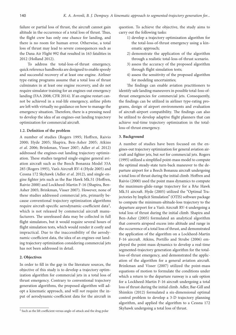
1) An Airbus A320 performs a northbound takeoff from Runway 36, shown in Figure 1, and starts the initial climb. The runway is situated at mean sea level. The take-off wing configuration of the A320 aircraft is 1+F, in which the slats are ex-tended to 18° and the flaps are extended to 10°. Wing configuration 1+F induces less drag than other takeoff configurations, and, hence, it gives a superior climb gradient and fuel efficiency (Airbus Industrie 2002).
144 K. A. Avrenli, B. J. Dempsey. A kinematic approach to segmented-trajectory generation for...
2) Although flap retraction on the A320 aircraft may occur as early as 400 ft (Airbus Industrie 2002), it is assumed that the flap retraction is scheduled to occur at 3,000 ft AGL at the time of the departure, in accordance with the Inter-national Civil Aviation Organization’s (ICAO) noise abatement departure procedure for close-in noise monitors (Roberson, Johns 2008).
3) Before the flaps are retracted during the initial climb, the A320 encounters a flock of birds, and multiple birds are ingested into both engines, as a result both engines undergo a total loss of thrust. It is assumed that the airport environ-ment is surrounded by an inhospitable terrain and large bodies of water, so the pilots have to attempt a turn-back maneuver to the departure airport to increase the odds of survivability.
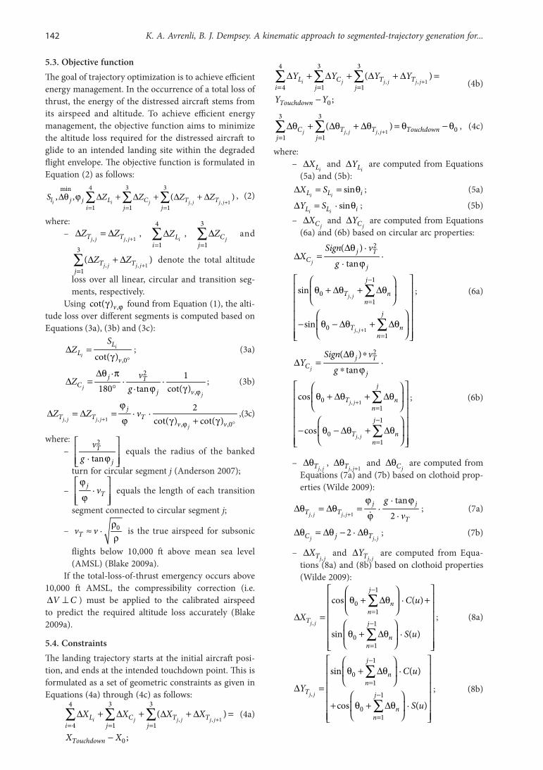
4) While the aircraft is heading north at a distance of 2.0 nautical miles (nm) north of Runway 18, the pilots initiate a turn-back maneuver to Run-way 18 (i.e. 0°; see Fig. 1). At this point, the air-craft weighs 70.0 tons.
5) It is assumed that the A320 does not have suffi-cient hydraulic power to change the wing config-uration due to the dual-engine failure. Thus, the wing configuration remains at 1+F throughout the landing maneuver.
6) Since the flaps cannot be extended, the landing speed has to be greater than typical landing speeds. It is assumed that the pilots maintain 160 KCAS (knots in calibrated airspeed) throughout the landing maneuver, which approximately equals the lowest selectable airspeed (i.e. LSV ) in this particular configuration. The LSV provides an appropriate margin to the stall speed. For fly-by-wire aircraft, like the A320, LSV equals 1.23 times
1S gV (Airbus 2002). By minimizing the airspeed, the pilots maximize the time aloft, and minimize the runway length requirements for landing roll.
7.2. Aerodynamic input dataThe steady-speed engines-out glide ratio of the Air-bus A320 is assessed using the simulation methodology (Avrenli, Dempsey 2014b) in a Joint Aviation Require-ments Flight Simulation Training Device (JAR-FSTD) A, Level D full flight simulator. The simulator is certified under the European Aviation Safety Agency (EASA) and Joint Aviation Authorities (JAA). The exact model of the simulated aircraft is the Airbus A320-232 with wingtip fences. The simulator has been tested in “normal”, “altern-ate”, and “direct” control laws of the Airbus A320 aircraft, and simulates real aircraft behavior in all normal and ab-normal flight operations. All simulations are conducted in standard day conditions, in which the air pressure equals 101.3 kPa and the air temperature equals 15°C at AMSL.
The steady-speed engines-out glide ratio is assessed at 160 KCAS for the bank angles of 0°, 10°, 20°, and maxϕ = 33°. The maximum bank (roll) angle is limited to 33° because the bank angle is one of the flight dynamics parameters limited by the Airbus’ fly-by-wire system. If the bank angle exceeds 33° with a side-stick input from the pilot, the aircraft automatically reduces the bank angle to 33° upon side-stick release in the “normal control law”. Thus, it is not practically possible4 to maintain a constant bank angle greater than 33° on the A320 aircraft when the air-craft is in the “normal control law” (Bugaj 2011).
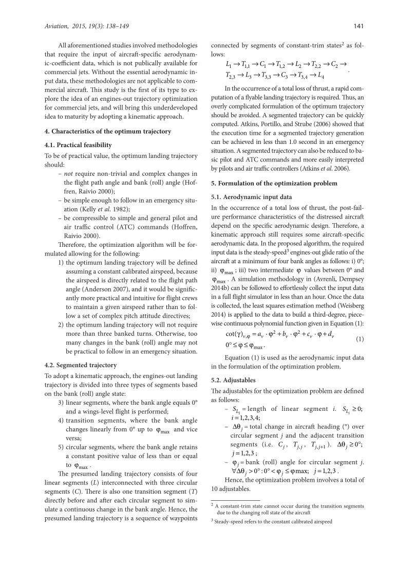
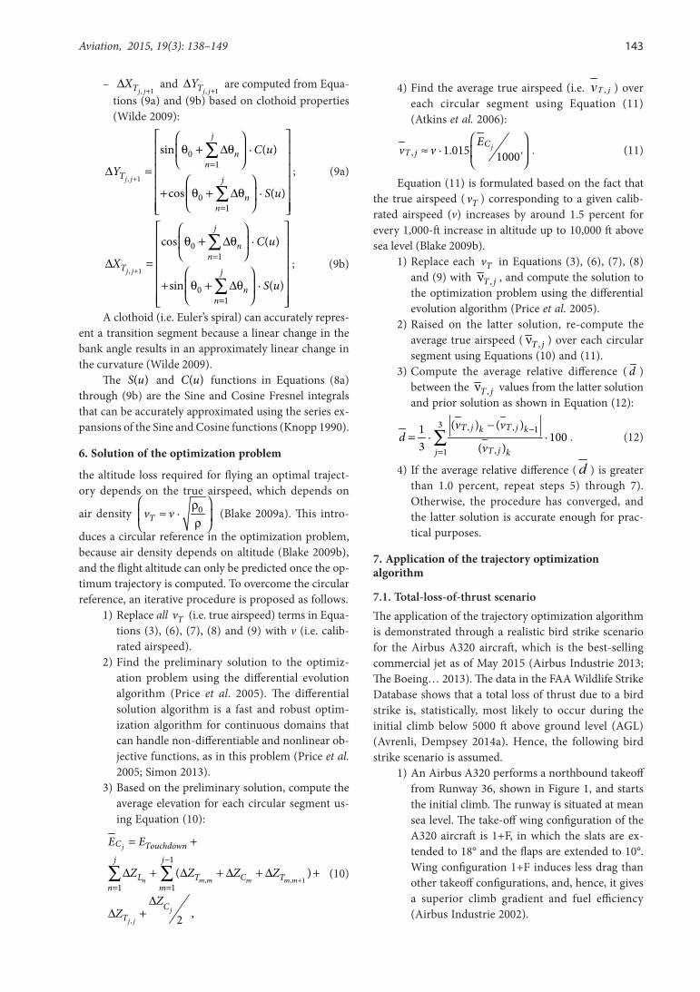
The total simulation time required for assessing the steady-speed engines-out glide ratios is less than 30 minutes, which is substantially less than the time that would otherwise be required to assess the aircraft-specific aerodynamic-coefficient data. The results from the flight simulation tests are plotted in Figure 2. As shown in Fig-ure 2, the steady-speed engines-out glide ratio at a given airspeed decreases with an increasing bank angle because
4 In the “normal law”, the maximum achievable bank angle equals 45° or 67°, depending on the particular flight conditions. In the “normal control law”, if the side-stick is not released, the bank angle keeps increasing up to 45° or 67° and then remains constant at this value until the side-stick is released. It is also possible to exceed the 33° bank angle if the aircraft is in “alternate law”.
0°
180°
270° 90°
18
36
2.0 nm
Fig. 1. Aircraft location at the beginning of the engines-out emergency landing (not drawn to scale)
Aviation, 2015, 19(3): 138–149 145
the aircraft partially loses lift, and there is increased drag acting on the aircraft during the banked turns (Anderson 2007). A piece-wise continuous, third-degree polynomial function is fitted to the data in Figure 2 using the least squares estimation method (Weisberg 2014):
3 2,cot( ) 0.000011 · 0.004017 ·
0.009051 · 13.0 ( )v
fϕγ = ϕ − ϕ +
ϕ + = ϕ (13)
160v KCAS= , 0 33° ≤ ϕ ≤ ° .
Equation (13) returns a coefficient of determina-tion, 2 1.0R = , which is plotted in Figure 2. It is used as an aerodynamic input datum for formulating the optim-ization problem.
7.3. Modeling assumptionsThe following assumptions are incorporated into the op-timization problem.
1) The aerodynamic roll rate of the A320 aircraft equals ϕ = 10°/sec.
2) Once the flight crew configures “landing gear down”, it takes no longer than 15 seconds for the landing gear to be fully extended and locked.
3) The aircraft is aligned with Runway 18 by the time it is 100 ft above ground level. This allows for the insertion of a “final approach waypoint”, which precedes a stabilizing final approach seg-ment. The “final approach waypoint” projects onto the beginning of Runway 18 threshold, and the landing trajectory is to be generated from the initial aircraft state to the “final approach waypoint”.
4) The pilots configure “landing gear down” no later than 15 seconds before the aircraft reaches the “final approach waypoint”.
5) Standard day conditions prevail during the en-gines-out landing, which corresponds to an air
pressure of 101.3 kPa and an air temperature of 15°C at mean sea level. If standard day condi-tions do not prevail, the pressure altitude is used in calculations instead of the geographic eleva-tion. The pressure altitude can be read from the pressure altimeter of the aircraft.
The first and the second assumptions are based on the observations made in the JAR-FSTD A, Level D full flight simulator. The third assumption basically prohibits banked turns below 100 ft to prevent possible wingtip collisions with ground objects. The fourth assumption enables sufficient time for the landing gear extension prior to touchdown. The landing gear extension results in an increased drag and a reduced engines-out glide ra-tio (Anderson 2007). When the landing gear is fully ex-tended in the full flight simulator, the resultant reduction in the steady-speed engines-out glide ratio is measured as being approximately 14% at 160 KCAS.
8. Results
8.1. Numerical solutionsThe optimum solution is computed using the MathWorld Software by Wolfram Research, which is a free resource built with Mathematica technology (Wolfram Research 2015). Since the optimization problem is formulated over a continuous domain, the procedure enables the compu-tation of the global optimum solution (Price et al. 2005). Table 1a lists the solutions for the adjustables. Table 1b provides the predicted altitude loss for each segment, and Table 1c shows the convergence criterion. Since
0.03% 1.0%d = < , the convergence criterion is met in the second iteration, and the second solution is the final solution to the optimization problem.
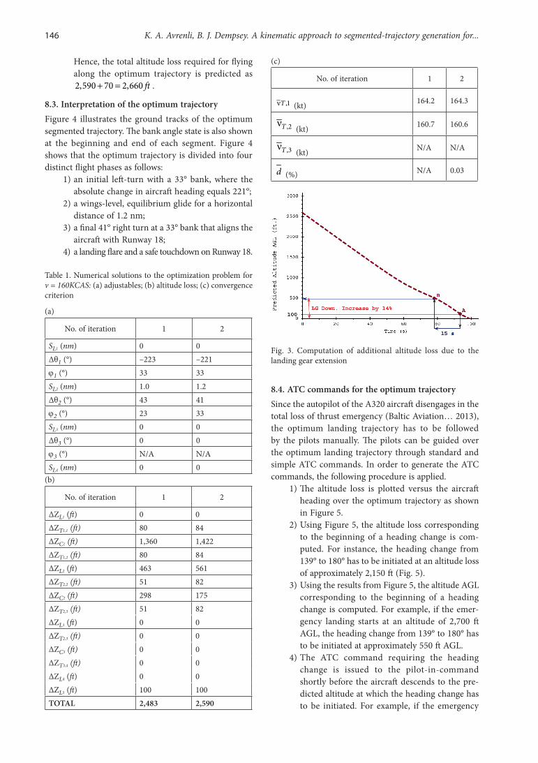
8.2. Additional altitude loss due to landing gear extensionTable 1b shows that the predicted altitude loss in order to fly along the optimum trajectory is 2,590 ft, but this does not include the additional altitude loss due to the landing gear extension. Based on the modeling assump-tions described in section 7.3, the following procedure is used to predict the additional altitude loss due to the landing gear extension.
1) The predicted altitude AGL vs. time is plotted over the optimum trajectory based on the solu-tion in Table 1b. The plot is shown in Fig. 3.
2) Using Figure 3, the time corresponding to 15 seconds before the aircraft is at 100 ft AGL is computed. This is the moment when the pilots must have the “landing gear down” configuration.
3) The required altitude loss from this moment on is increased by 14%. In this example, the additional altitude loss due to the landing gear extension is predicted as 500 · 0.14 70 ft= .
0
2
4
6
8
10
12
14
16
18
20
0 10 20 30 40
Engi
nes
-ou
t Glid
e R
atio
Bank Angle ( ° )
Airspeed = 160 KCAS, Wing Configuration 1+F
Fig. 2. Predicted engines-out glide ratio for the A320 aircraft during a steady-speed descent (wing configuration = 1 + F, landing gear up, aircraft gross weight = 70.0 tons)
146 K. A. Avrenli, B. J. Dempsey. A kinematic approach to segmented-trajectory generation for...
Hence, the total altitude loss required for flying along the optimum trajectory is predicted as 2,590 70 2,660 ft+ = .
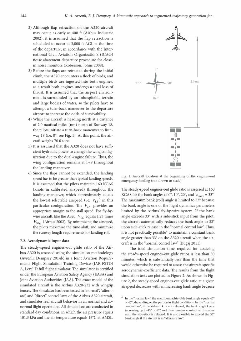
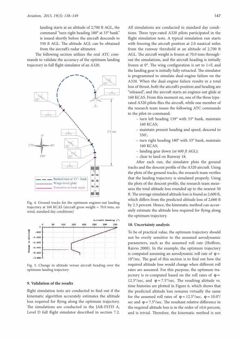
8.3. Interpretation of the optimum trajectoryFigure 4 illustrates the ground tracks of the optimum segmented trajectory. The bank angle state is also shown at the beginning and end of each segment. Figure 4 shows that the optimum trajectory is divided into four distinct flight phases as follows:
1) an initial left-turn with a 33° bank, where the absolute change in aircraft heading equals 221°;
2) a wings-level, equilibrium glide for a horizontal distance of 1.2 nm;
3) a final 41° right turn at a 33° bank that aligns the aircraft with Runway 18;
4) a landing flare and a safe touchdown on Runway 18.
Table 1. Numerical solutions to the optimization problem for v = 160KCAS: (a) adjustables; (b) altitude loss; (c) convergence criterion
(a)
No. of iteration 1 2
SL1 (nm) 0 0Δθ1 (°) –223 –221ϕ1 (°) 33 33SL2 (nm) 1.0 1.2Δθ2 (°) 43 41ϕ2 (°) 23 33SL3 (nm) 0 0Δθ3 (°) 0 0ϕ3 (°) N/A N/ASL4 (nm) 0 0
(b)
No. of iteration 1 2
ΔZL1 (ft) 0 0ΔZT1,1 (ft) 80 84ΔZC1 (ft) 1,360 1,422ΔZT1,2 (ft) 80 84ΔZL2 (ft) 463 561ΔZT2,2 (ft) 51 82ΔZC2 (ft) 298 175ΔZT2,3 (ft) 51 82ΔZL3 (ft) 0 0ΔZT2,3 (ft) 0 0ΔZC3 (ft) 0 0ΔZT3,4 (ft) 0 0ΔZL4 (ft) 0 0ΔZL5 (ft) 100 100TOTAL 2,483 2,590
(c)
No. of iteration 1 2
,1Tν (kt) 164.2 164.3
,2Tν (kt) 160.7 160.6
,3Tν (kt) N/A N/A
d (%) N/A 0.03
Fig. 3. Computation of additional altitude loss due to the landing gear extension
8.4. ATC commands for the optimum trajectorySince the autopilot of the A320 aircraft disengages in the total loss of thrust emergency (Baltic Aviation… 2013), the optimum landing trajectory has to be followed by the pilots manually. The pilots can be guided over the optimum landing trajectory through standard and simple ATC commands. In order to generate the ATC commands, the following procedure is applied.
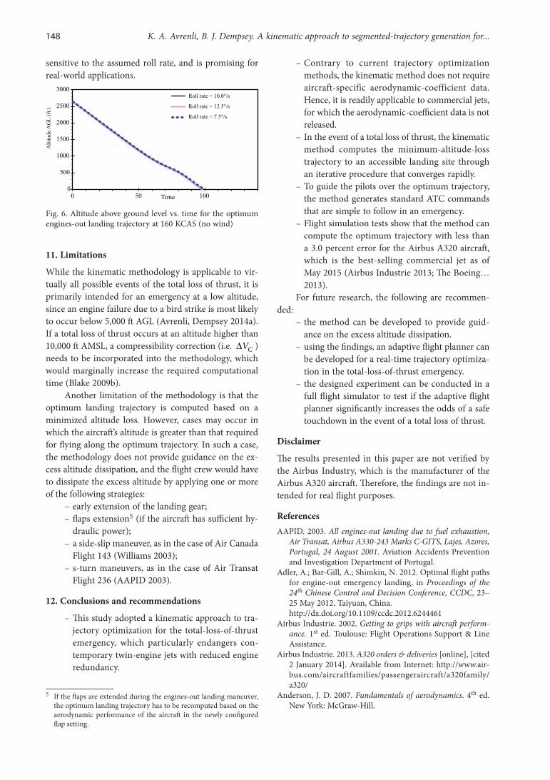
1) The altitude loss is plotted versus the aircraft heading over the optimum trajectory as shown in Figure 5.
2) Using Figure 5, the altitude loss corresponding to the beginning of a heading change is com-puted. For instance, the heading change from 139° to 180° has to be initiated at an altitude loss of approximately 2,150 ft (Fig. 5).
3) Using the results from Figure 5, the altitude AGL corresponding to the beginning of a heading change is computed. For example, if the emer-gency landing starts at an altitude of 2,700 ft AGL, the heading change from 139° to 180° has to be initiated at approximately 550 ft AGL.
4) The ATC command requiring the heading change is issued to the pilot-in-command shortly before the aircraft descends to the pre-dicted altitude at which the heading change has to be initiated. For example, if the emergency
Aviation, 2015, 19(3): 138–149 147
landing starts at an altitude of 2,700 ft AGL, the command “turn right heading 180° at 33° bank” is issued shortly before the aircraft descends to 550 ft AGL. The altitude AGL can be obtained from the aircraft’s radar altimeter.
The following section utilizes the oral ATC com-mands to validate the accuracy of the optimum landing trajectory in full flight simulator of an A320.
0°
180°
270° 90°
18
36
2.0 nm
Banked turn at 33°– bankWings-level glideTransition in bank angle
33°
33°
33°
33°
Fig. 4. Ground tracks for the optimum engines-out landing trajectory at 160 KCAS (aircraft gross weight = 70.0 tons, no wind, standard day conditions)
Fig. 5. Change in altitude versus aircraft heading over the optimum landing trajectory
9. Validation of the results
flight simulation tests are conducted to find out if the kinematic algorithm accurately estimates the altitude loss required for flying along the optimum trajectory. The simulations are conducted in the JAR-FSTD A, Level D full flight simulator described in section 7.2.
All simulations are conducted in standard day condi-tions. Three type-rated A320 pilots participated in the flight simulation tests. A typical simulation run starts with freezing the aircraft position at 2.0 nautical miles from the runway threshold at an altitude of 2,700 ft AGL. The aircraft weight is frozen at 70.0 tons through-out the simulations, and the aircraft heading is initially frozen at 0°. The wing configuration is set to 1+F, and the landing gear is initially fully retracted. The simulator is programmed to simulate dual-engine failure on the A320. When the dual-engine failure results in a total loss of thrust, both the aircraft’s position and heading are “released”, and the aircraft starts an engines-out glide at 160 KCAS. From this moment on, one of the three type-rated A320 pilots flies the aircraft, while one member of the research team issues the following ATC commands to the pilot-in-command:
– turn left heading 139° with 33° bank, maintain 160 KCAS;
– maintain present heading and speed, descend to 550’;
– turn right heading 180° with 33° bank, maintain 160 KCAS;
– landing gear down (at 600 ft AGL); – clear to land on Runway 18.
After each run, the simulator plots the ground tracks and the descent profile of the A320 aircraft. Using the plots of the ground tracks, the research team verifies that the landing trajectory is simulated properly. Using the plots of the descent profile, the research team meas-ures the total altitude loss rounded up to the nearest 50 ft. The average simulated altitude loss is found as 2,600 ft, which differs from the predicted altitude loss of 2,660 ft by 2.3 percent. Hence, the kinematic method can accur-ately estimate the altitude loss required for flying along the optimum trajectory.
10. Uncertainty analysis
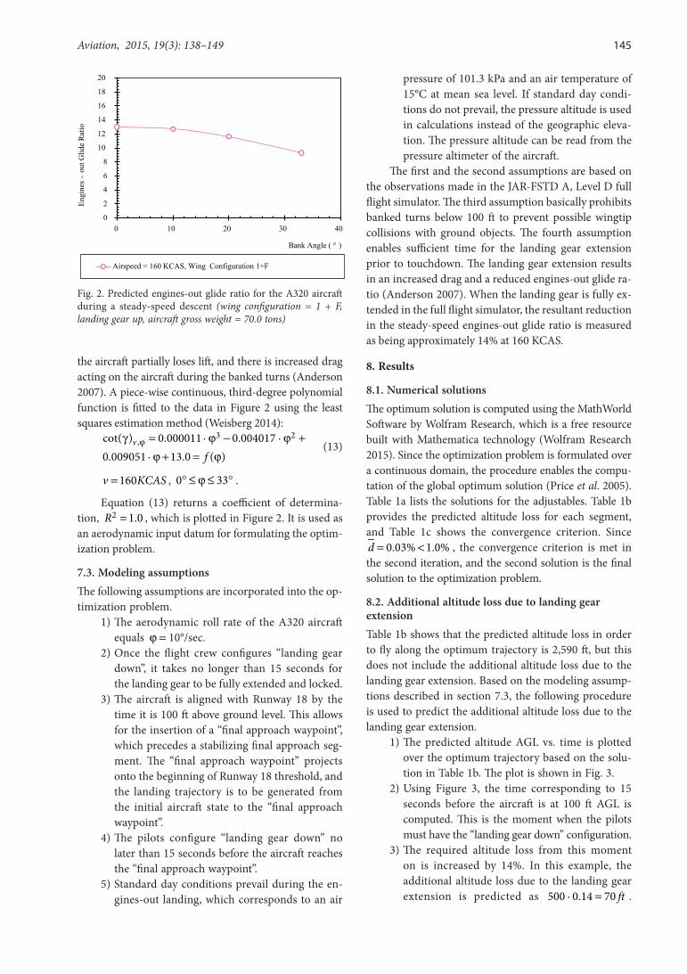
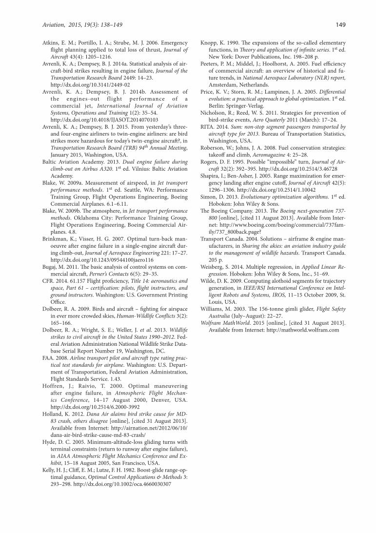
To be of practical value, the optimum trajectory should not be overly sensitive to the assumed aerodynamic parameters, such as the assumed roll rate (Hoffren, Raivio 2000). In the example, the optimum trajectory is computed assuming an aerodynamic roll rate of ϕ =10°/sec. The goal of this section is to find out how the required altitude loss would change when different roll rates are assumed. For this purpose, the optimum tra-jectory is re-computed based on the roll rates of ϕ =12.5°/sec, and ϕ = 7.5°/sec. The resulting altitude vs. time histories are plotted in Figure 6, which shows that the predicted altitude loss remains virtually the same for the assumed roll rates of ϕ = 12.5°/sec, ϕ = 10.0°/sec and ϕ = 7.5°/sec. The resultant relative difference in the required altitude loss is in the order of ±0.6 percent, and is trivial. Therefore, the kinematic method is not
148 K. A. Avrenli, B. J. Dempsey. A kinematic approach to segmented-trajectory generation for...
sensitive to the assumed roll rate, and is promising for real-world applications.
0
500
1000
1500
2000
2500
3000
0 50 100
Alt
itud
e A
GL
(ft
.)
Time
Roll rate = 10.0°/s
Roll rate = 12.5°/s
Roll rate = 7.5°/s
Fig. 6. Altitude above ground level vs. time for the optimum engines-out landing trajectory at 160 KCAS (no wind)
11. Limitations
While the kinematic methodology is applicable to vir-tually all possible events of the total loss of thrust, it is primarily intended for an emergency at a low altitude, since an engine failure due to a bird strike is most likely to occur below 5,000 ft AGL (Avrenli, Dempsey 2014a). If a total loss of thrust occurs at an altitude higher than 10,000 ft AMSL, a compressibility correction (i.e. CV∆ ) needs to be incorporated into the methodology, which would marginally increase the required computational time (Blake 2009b).
Another limitation of the methodology is that the optimum landing trajectory is computed based on a minimized altitude loss. However, cases may occur in which the aircraft’s altitude is greater than that required for flying along the optimum trajectory. In such a case, the methodology does not provide guidance on the ex-cess altitude dissipation, and the flight crew would have to dissipate the excess altitude by applying one or more of the following strategies:
– early extension of the landing gear; – flaps extension5 (if the aircraft has sufficient hy-draulic power);
– a side-slip maneuver, as in the case of Air Canada Flight 143 (Williams 2003);
– s-turn maneuvers, as in the case of Air Transat Flight 236 (AAPID 2003).
12. Conclusions and recommendations
– This study adopted a kinematic approach to tra-jectory optimization for the total-loss-of-thrust emergency, which particularly endangers con-temporary twin-engine jets with reduced engine redundancy.
5 If the flaps are extended during the engines-out landing maneuver, the optimum landing trajectory has to be recomputed based on the aerodynamic performance of the aircraft in the newly configured flap setting.
– Contrary to current trajectory optimization methods, the kinematic method does not require aircraft-specific aerodynamic-coefficient data. Hence, it is readily applicable to commercial jets, for which the aerodynamic-coefficient data is not released.
– In the event of a total loss of thrust, the kinematic method computes the minimum-altitude-loss trajectory to an accessible landing site through an iterative procedure that converges rapidly.
– To guide the pilots over the optimum trajectory, the method generates standard ATC commands that are simple to follow in an emergency.
– Flight simulation tests show that the method can compute the optimum trajectory with less than a 3.0 percent error for the Airbus A320 aircraft, which is the best-selling commercial jet as of May 2015 (Airbus Industrie 2013; The Boeing… 2013).
For future research, the following are recommen-ded:
– the method can be developed to provide guid-ance on the excess altitude dissipation.
– using the findings, an adaptive flight planner can be developed for a real-time trajectory optimiza-tion in the total-loss-of-thrust emergency.
– the designed experiment can be conducted in a full flight simulator to test if the adaptive flight planner significantly increases the odds of a safe touchdown in the event of a total loss of thrust.
Disclaimer
The results presented in this paper are not verified by the Airbus Industry, which is the manufacturer of the Airbus A320 aircraft. Therefore, the findings are not in-tended for real flight purposes.
ReferencesAAPID. 2003. All engines-out landing due to fuel exhaustion,
Air Transat, Airbus A330-243 Marks C-GITS, Lajes, Azores, Portugal, 24 August 2001. Aviation Accidents Prevention and Investigation Department of Portugal.
Adler, A.; Bar-Gill, A.; Shimkin, N. 2012. Optimal flight paths for engine-out emergency landing, in Proceedings of the 24th Chinese Control and Decision Conference, CCDC, 23–25 May 2012, Taiyuan, China.
http://dx.doi.org/10.1109/ccdc.2012.6244461Airbus Industrie. 2002. Getting to grips with aircraft perform-
ance. 1st ed. Toulouse: Flight Operations Support & Line Assistance.
Airbus Industrie. 2013. A320 orders & deliveries [online], [cited 2 January 2014]. Available from Internet: http://www.air-bus.com/aircraftfamilies/passengeraircraft/a320family/a320/
Anderson, J. D. 2007. Fundamentals of aerodynamics. 4th ed. New york: McGraw-Hill.
Aviation, 2015, 19(3): 138–149 149
Atkins, E. M.; Portillo, I. A.; Strube, M. J. 2006. Emergency flight planning applied to total loss of thrust, Journal of Aircraft 43(4): 1205–1216.
Avrenli, K. A.; Dempsey, B. J. 2014a. Statistical analysis of air-craft-bird strikes resulting in engine failure, Journal of the Transportation Research Board 2449: 14–23.
http://dx.doi.org/10.3141/2449-02Avrenli, K. A.; Dempsey, B. J. 2014b. Assessment of
the engines-out f l ight performance of a commercial jet, International Journal of Aviation Systems, Operations and Training 1(2): 35–54.
http://dx.doi.org/10.4018/IJASOT.2014070103Avrenli, K. A.; Dempsey, B. J. 2015. From yesterday’s three-
and four-engine airliners to twin-engine airliners: are bird strikes more hazardous for today’s twin-engine aircraft?, in Transportation Research Board (TRB) 94th Annual Meeting, January 2015, Washington, USA.
Baltic Aviation Academy. 2013. Dual engine failure during climb-out on Airbus A320. 1st ed. Vilnius: Baltic Aviation Academy.
Blake, W. 2009a. Measurement of airspeed, in Jet transport performance methods. 1st ed. Seattle, WA: Performance Training Group, Flight Operations Engineering, Boeing Commercial Airplanes. 6.1–6.11.
Blake, W. 2009b. The atmosphere, in Jet transport performance methods. Oklahoma City: Performance Training Group, Flight Operations Engineering, Boeing Commercial Air-planes. 4.8.
Brinkman, K.; Visser, H. G. 2007. Optimal turn-back man-oeuvre after engine failure in a single-engine aircraft dur-ing climb-out, Journal of Aerospace Engineering 221: 17–27. http://dx.doi.org/10.1243/09544100jaero116
Bugaj, M. 2011. The basic analysis of control systems on com-mercial aircraft, Perner’s Contacts 6(5): 29–35.
CFR. 2014. 61.157 Flight proficiency, Title 14: aeronautics and space, Part 61 – certification: pilots, flight instructors, and ground instructors. Washington: U.S. Government Printing Office.
Dolbeer, R. A. 2009. Birds and aircraft – fighting for airspace in ever more crowded skies, Human-Wildlife Conflicts 3(2): 165–166.
Dolbeer, R. A.; Wright, S. E.; Weller, J. et al. 2013. Wildlife strikes to civil aircraft in the United States 1990–2012. Fed-eral Aviation Administration National Wildlife Strike Data-base Serial Report Number 19, Washington, DC.
FAA. 2008. Airline transport pilot and aircraft type rating prac-tical test standards for airplane. Washington: U.S. Depart-ment of Transportation, Federal Aviation Administration, Flight Standards Service. 1.43.
Hoffren, J.; Raivio, T. 2000. Optimal maneuvering after engine failure, in Atmospheric Flight Mechan-ics Conference, 14–17 August 2000, Denver, USA. http://dx.doi.org/10.2514/6.2000-3992
Holland, K. 2012. Dana Air alaims bird strike cause for MD-83 crash, others disagree [online], [cited 31 August 2013]. Available from Internet: http://airnation.net/2012/06/10/dana-air-bird-strike-cause-md-83-crash/
Hyde, D. C. 2005. Minimum-altitude-loss gliding turns with terminal constraints (return to runway after engine failure), in AIAA Atmospheric Flight Mechanics Conference and Ex-hibit, 15–18 August 2005, San Francisco, USA.
Kelly, H. J.; Cliff, E. M.; Lutze, F. H. 1982. Boost-glide range-op-timal guidance, Optimal Control Applications & Methods 3: 293–298. http://dx.doi.org/10.1002/oca.4660030307
Knopp, K. 1990. The expansions of the so-called elementary functions, in Theory and application of infinite series. 1st ed. New york: Dover Publications, Inc. 198–208 p.
Peeters, P. M.; Middel, J.; Hoolhorst, A. 2005. Fuel efficiency of commercial aircraft: an overview of historical and fu-ture trends, in National Aerospace Laboratory (NLR) report, Amsterdam, Netherlands.
Price, K. V.; Storn, R. M.; Lampinen, J. A. 2005. Differential evolution: a practical approach to global optimization. 1st ed. Berlin: Springer-Verlag.
Nicholson, R.; Reed, W. S. 2011. Strategies for prevention of bird-strike events, Aero Quaterly 2011 (March): 17–24.
RITA. 2014. Sum: non-stop segment passengers transported by aircraft type for 2013. Bureau of Transportation Statistics, Washington, USA.
Roberson, W.; Johns, J. A. 2008. Fuel conservation strategies: takeoff and climb, Aeromagazine 4: 25–28.
Rogers, D. F. 1995. Possible “impossible” turn, Journal of Air-craft 32(2): 392–395. http://dx.doi.org/10.2514/3.46728
Shapira, I.; Ben-Asher, J. 2005. Range maximization for emer-gency landing after engine cutoff, Journal of Aircraft 42(5): 1296–1306. http://dx.doi.org/10.2514/1.10042
Simon, D. 2013. Evolutionary optimization algorithms. 1st ed. Hoboken: John Wiley & Sons.
The Boeing Company. 2013. The Boeing next-generation 737-800 [online], [cited 11 August 2013]. Available from Inter-net: http://www.boeing.com/boeing/commercial/737fam-ily/737_800back.page?
Transport Canada. 2004. Solutions – airframe & engine man-ufacturers, in Sharing the akies: an aviation industry guide to the management of wildlife hazards. Transport Canada. 205 p.
Weisberg, S. 2014. Multiple regression, in Applied Linear Re-gression. Hoboken: John Wiley & Sons, Inc., 51–69.
Wilde, D. K. 2009. Computing alothoid segments for trajectory generation, in IEEE/RSJ International Conference on Intel-ligent Robots and Systems, IROS, 11–15 October 2009, St. Louis, USA.
Williams, M. 2003. The 156-tonne gimli glider, Flight Safety Australia (July–August): 22–27.
Wolfram MathWorld. 2015 [online], [cited 31 August 2013]. Available from Internet: http://mathworld.wolfram.com
Related Documents