A JRC FIWARE Testbed for SMART Building and Infrastructures Implementation of the FIWARE platform for performance testing and heterogeneous sensor nodes Vaglica, G., Bono, F., Renaldi, G. 2020 EUR 30038 EN

Welcome message from author
This document is posted to help you gain knowledge. Please leave a comment to let me know what you think about it! Share it to your friends and learn new things together.
Transcript

A JRC FIWARE Testbed for SMART Building and Infrastructures
Implementation of the
FIWARE platform for performance testing and
heterogeneous sensor nodes
Vaglica, G., Bono, F., Renaldi, G.
2020
EUR 30038 EN

This publication is a Technical report by the Joint Research Centre (JRC), the European Commission’s science and knowledge service. It aims to provide evidence-based scientific support to the European policymaking process. The scientific output expressed does not imply a
policy position of the European Commission. Neither the European Commission nor any person acting on behalf of the Commission is responsible for the use that might be made of this publication. For information on the methodology and quality underlying the data used in this publication for which the source is neither Eurostat nor other Commission services, users should contact the referenced source. The designations employed and the presentation of material on the maps do not imply the expression of any opinion whatsoever on the part of the European Union concerning the legal status of any country, territory, city or area or of its authorities, or concerning the delimitation of its frontiers or boundaries.
EU Science Hub
https://ec.europa.eu/jrc
JRC118952
EUR 30038 EN
PDF ISBN 978-92-76-14658-2 ISSN 1831-9424 doi:10.2760/314017
Luxembourg: Publications Office of the European Union, 2020
© European Union, 2020
The reuse policy of the European Commission is implemented by the Commission Decision 2011/833/EU of 12 December 2011 on the reuse of Commission documents (OJ L 330, 14.12.2011, p. 39). Except otherwise noted, the reuse of this document is authorised under the Creative Commons Attribution 4.0 International (CC BY 4.0) licence (https://creativecommons.org/licenses/by/4.0/). This means that reuse is allowed provided appropriate credit is given and any changes are indicated. For any use or reproduction of photos or other
material that is not owned by the EU, permission must be sought directly from the copyright holders.
All content © European Union, 2020, except: cover image, jamesteohart, © Adobe Stock, 2019
How to cite this report: G. Vaglica, F. Bono, G. Renaldi, A JRC FIWARE Testbed for SMART Building and Infrastructures, EUR 30038 EN, Publications Office of the European Union, Luxembourg, 2020, ISBN 978-92-76-14658-2, doi:10.2760/314017, JRC118952

Contents
1 Introduction 6
2 Architecture of FIWARE 8
2.1 Orion Context Broker . . . . . . . . . . . . . . . . . . . . . . . . . . . . . . . . . 8
2.1.1 Context element . . . . . . . . . . . . . . . . . . . . . . . . . . . . . . . . 8
2.2 Database for the context information . . . . . . . . . . . . . . . . . . . . . . . . . 9
2.3 IoT agent . . . . . . . . . . . . . . . . . . . . . . . . . . . . . . . . . . . . . . . . 9
2.4 Cygnus . . . . . . . . . . . . . . . . . . . . . . . . . . . . . . . . . . . . . . . . . 10
2.5 Historical Database . . . . . . . . . . . . . . . . . . . . . . . . . . . . . . . . . . . 11
2.6 Interaction of FIWARE components . . . . . . . . . . . . . . . . . . . . . . . . . 12
3 Implementation of FIWARE in the JRC site 14
3.1 DMZ architecture . . . . . . . . . . . . . . . . . . . . . . . . . . . . . . . . . . . . 14
3.2 Configuration of FIWARE services . . . . . . . . . . . . . . . . . . . . . . . . . . 15
3.2.1 Data structure . . . . . . . . . . . . . . . . . . . . . . . . . . . . . . . . . 16
3.2.2 Wireless Sensor Network components . . . . . . . . . . . . . . . . . . . . 17
3.2.3 Orion Context Broker . . . . . . . . . . . . . . . . . . . . . . . . . . . . . 17
3.2.4 IoT Agent . . . . . . . . . . . . . . . . . . . . . . . . . . . . . . . . . . . . 18
3.2.5 MongoDB for the context information . . . . . . . . . . . . . . . . . . . . 19
3.2.6 Cygnus . . . . . . . . . . . . . . . . . . . . . . . . . . . . . . . . . . . . . 19
3.2.7 Cygnus optimization . . . . . . . . . . . . . . . . . . . . . . . . . . . . . . 20
3.2.8 PostgreSQL for the data history . . . . . . . . . . . . . . . . . . . . . . . 21
4 Interaction between the gateway and the IoT agent 23
4.1 The Ultralight 2.0 protocol . . . . . . . . . . . . . . . . . . . . . . . . . . . . . . 23
4.2 Python script . . . . . . . . . . . . . . . . . . . . . . . . . . . . . . . . . . . . . . 23
5 Grafana 27
6 Future enhancements 30
6.1 Custom IoT agent . . . . . . . . . . . . . . . . . . . . . . . . . . . . . . . . . . . 30
6.2 VM-C . . . . . . . . . . . . . . . . . . . . . . . . . . . . . . . . . . . . . . . . . . 30
6.3 Security in the IoT network . . . . . . . . . . . . . . . . . . . . . . . . . . . . . . 31
6.4 Security in the FIWARE system . . . . . . . . . . . . . . . . . . . . . . . . . . . 33
6.4.1 Authentication system . . . . . . . . . . . . . . . . . . . . . . . . . . . . . 33
6.4.2 Authorization system . . . . . . . . . . . . . . . . . . . . . . . . . . . . . 33
1

List of Figures
1 IoT agent strategies. . . . . . . . . . . . . . . . . . . . . . . . . . . . . . . . . . . 10
2 Cygnus architecture in the default FIWARE configuration. . . . . . . . . . . . . 11
3 Basic interaction in a FIWARE system. . . . . . . . . . . . . . . . . . . . . . . . 12
4 FIWARE implementation in the JRC. . . . . . . . . . . . . . . . . . . . . . . . . 15
5 Cygnus architecture with improvements. . . . . . . . . . . . . . . . . . . . . . . . 21
6 JRC FIWARE GUI loging page. . . . . . . . . . . . . . . . . . . . . . . . . . . . 27
7 JRC FIWARE: wireless sensor nodes and base details page with geographicalposition. . . . . . . . . . . . . . . . . . . . . . . . . . . . . . . . . . . . . . . . . . 28
8 Accelerometer acquisition visualization page. . . . . . . . . . . . . . . . . . . . . 28
9 Multiple axes details visualization of accelerometer wireless node. . . . . . . . . . 29
10 JRC FIWARE acquired data listing. . . . . . . . . . . . . . . . . . . . . . . . . . 29
11 FIWARE implementation with improvements. . . . . . . . . . . . . . . . . . . . . 30
12 Security interaction between a sensor and the gateway, in an IoT network. . . . . 31
13 Interaction scheme between PEP, PDP and IdM. . . . . . . . . . . . . . . . . . . 34
2

Acronyms
AI Artificial Intelligence
ACK ACKnowledgement
AES Advanced Encryption Standard
API Application Program Interface
CBC Cipher Block Chaining
CEF Connecting Europe Facility
CKAN Comprehensive Knowledge Archive Network
COM COMmunication port
cURL Client URL Request Library
DB DataBase
DMZ Demilitarized Zone
DMRZ Demilitarized Resource Zone
EC European Commission
FIFO First In First Out
GE Generic Enabler
GUI Graphical User Interface
HDD Hard Disk Drive
HDFS Hadoop Distributed File System
HTTP Hypertext Transfer Protocol
ICT Information and Communication Technology
IdM Identity Manager
IOPS Input/Output operations Per Second
IoT Internet of Things
IP Internet Protocol
JRC Joint Research Centre
JSON JavaScript Object Notation
KVM Kernel-based Virtual Machine
LoRaWAN Long Range Wide Area Network
LWM2M LightWeight Machine-TO-Machine
MITM Man In The Middle
MQTT Message Queuing Telemetry Transport
3

MSCL MicroStrain Communication Library
NGSI Next Generation Service Interfaces
OCB Orion Context Broker
OS Open Source
OS-level Operating System-level
PEP Policy Enforcement Point
PDP Policy Decision Point
QoS Quality of Service
REST REpresentational State Transfer
SaaS Software as a Service
SHM Structural Health Monitoring
SQL Structured Query Language
SSD Solid State Drive
STH Short-Term History
TTL Time-To-Live
UL UltraLight
URL Uniform Resource Locator
VLAN Virtual Local Area Network
VM Virtual Machine
WAN Wide Area Network
WSN Wireless Sensor Network
XACML eXtensible Access Control Markup Language
4

Abstract
The present work reports on the activities for the implementation of a SMART Citytestbed based on the EC CEF Context Broker and the open source platform FIWARE.The system architecture complies with the EC JRC network IT security requirements andprovided the testbed for performance testing and analysis of the challenges for the inte-gration of IoT and wireless commercial devices in a Smart City system. The integrationof the wireless sensor network systems in use at the JRC E.4 Unit for the monitoringof structures during experimental tests provides real-world scenarios for realistic testing.The implemented testbed will provide support for future works and developments of largersystems and integration with heterogeneous Internet of Things (IoT) devices, numerouscommunication protocols and the definition of strategies for big data analysis and urbanintelligence. The work was performed by Giovanni Vaglica from the Politecnico di Torinoduring his traineeship at the JRC.
5


1 Introduction
The strategy of connecting sensors to remote control systems in cities is not new. The firstsystems used radio transmission to allow the monitoring of critical components (e.g. sewagepumps) but hardware was initially expensive and required custom set up and software.
With the cost of sensor devices constantly dropping and the advent of new radio modules,standard communication protocols and hardware interfaces, the paradigm of SMART Citiesevolved to unprecedented capability. Contemporary cities can now connect a number of devicesto collect real time information on the urban environment in support of decision making ofPublic Administrations and towards an improved management of resources.
However, despite the wide availability of sensors and communication devices, the integrationprocess is still rather complex; vendors may lock-in their systems and hardware and, as aconsequence, data interoperability is often missing; this translates into the impossibility to fullyexploit the potential of interconnected systems and data exchange.
One possibility to overcome the difficulty of adopting heterogeneous devices for optimal SmartCity implementations is offered by the embracing of open source platforms and standards. Al-though the adoption of open source (OS) might lead to an initial additional effort and possiblythe fear of lack of support and updates, there exist many examples of OS systems with per-formance and support from communities fully comparable to commercial systems (one exampleabove all being the operative system Linux).
The innovative trends of the, so-called, Future Internet era are based on the advent of newtechnologies and solutions such as cloud computing, the concept of software as a service (SaaS)and the IoT. The European Commission funded innovative projects for the development of aEuropean cloud-based open service delivery platform, paving the way for the development ofthe FIWARE system. As reported by the vision [1] of the initial FIWARE project, the aim is todevelop the Core Platform of the Future Internet and to “increase the global competitiveness ofthe European ICT economy by introducing an innovative infrastructure for cost-effective creationand delivery of versatile digital services, providing high QoS and security guarantees”. Suchplatform had to be open and based on components, called Generic Enablers (GEs), providingreusable functionalities to be applied in different applications.
The FIWARE initial project later evolved into an open source Smart City platform currentlyadopted by a number of European Cities (Malaga, Copenhagen, Vienna, Helsinki among theothers) meeting consensus and adoption in extra-EU cities (e.g. in Japan and Brazil).
Moreover, the core component of the FIWARE platform, the Context Broker, was chosen in 2018by the EU Member States as a standard component [2] of the Connecting European Facility(CEF) Digital Building Blocks. The Context Broker is designed to manage context informationon a large scale for information sharing and data exchange.
Given the strategic importance of the FIWARE solution within the European policies of digitalinnovation and transformation, the SMARTBUILD project aimed at investigating the challengesand constraints of such platform for the integration of SMART buildings and infrastructures intolarger Smart City systems. Monitoring applications for the assessment of critical infrastructures,like structural health monitoring (SHM) systems in bridges, requires high acquisition rates ofmany sensors, and represents a high demanding application for data exchange, in terms of datastream, data storage and processing.
Moreover, within the JRC E.4 Unit’s SMART PROTECT project started in 2019, the integrationof video streaming and AI-based analysis for security of public spaces into the FIWARE platformis another demanding scenario that will be addressed in order to find feasible solutions for theimplementation of security systems in Smart and Safe Cities.
6

The present work was carried out during the traineeship of Giovanni Vaglica, from the Politecnicodi Torino, with the objective of implementing a FIWARE testbed at the JRC E.4 Unit forthe future integration of heterogeneous sensors and wireless networks in order to assess theperformance and constraint of such platform.
The following paragraphs describe in detail the initial system architecture compliant to the ITsecurity requirements of the JRC network. Therefore, the solution here presented confronts withadditional constraints otherwise not necessarily needed in cities implementations.
The functioning FIWARE testbed allowed the initial testing of the performance and the analysisof the integration of the commercial WSN system in use at the Unit for structural monitoringduring experimental tests. The implemented testbed will provide support for future worksand developments of larger systems along with the integration with heterogeneous IoT devices,numerous communication protocols and big data analysis.
7

2 Architecture of FIWARE
The FIWARE system is composed of a set of elements, each of which is contained in a specificDocker container [3]. A Docker container is an isolated OS-level environment that bundlessoftware components including all applications, libraries and configuration files. The use of suchservice allows to have a scalable and flexible environment, that fits perfectly with the structureof FIWARE. In addition, all containers are run by a single operating-system kernel: in thisway they are more computationally lightweight than the virtual machines, as explained also inthe article “An updated performance comparison of virtual machines and Linux containers” [4],where it is underlined how Docker equals or exceeds KVM1 performance in all the use casestested.
The installation of Docker and docker-compose services are necessary in order to ensure thecorrect functioning of the system.
Let us analyze now, in the following paragraphs, the main services of FIWARE.
2.1 Orion Context Broker
The Orion Context Broker (OCB) [5] is the core element of the FIWARE platform, completelywritten in C++ language. It relies on an NGSI protocol with the following functionalities:
� Managing the context elements and their availability.
� Updating data and JSON format information through specific queries.
� Managing all the registration of a specific resources and subscriptions to context services.
� Notifing a service on the arrival of specific data2.
All the interactions between OCB and other FIWARE services are performed through the NGSI,a REST-based protocol that provides with the possibility to encapsulate the context elements.The REST paradigm is used to define a web service and the client-server interactions. Thismeans that each element is defined by an URL and the OCB can manage the queries through:
� A GET request, used to read a context element.
� A POST request, used to create a context element.
� A PUT request, used to update a context element.
� A DELETE request, used to eliminate a context element.
2.1.1 Context element
The context element is the data structure used for exchanging information related to a specificentity. Generally it is described by:
� Id and type of entity.
1The KVM (Kernel-based Virtual Machine) is an open virtualization system built into Linux OS.2Linked to the resource to which it was previously registered.
8

� List of [attribute name/attribute type/attribute values] that allows to give informationabout the entity.
� Name of the attribute domain.
� List of elements to apply to all the attributes of a specific domain.
All these information are written with a JSON syntax.
2.2 Database for the context information
The database used to contain all the entities is MongoDB [6], a non-relational document-orienteddatabase program. It is based on collections that regroup different documents in JSON format;such format ensures a perfect interoperability between the database itself and the NGSI protocolused by the FIWARE services.
The interaction with this DB is usually performed only by the FIWARE services, making theprocess transparent for the user. Nevertheless, there is however the possibility to interact directlywith it through the OCB. As an example, it could be possible to send some messages in orderto read (GET request) or update (POST request) the entities contained in the MongoDB. Inany case, this type of approach is strongly not recommended.
2.3 IoT agent
The task of the IoT agent [7] is to convert WSN data into valid NGSI requests, in the proper for-mat for OCB. Given the existence of different IoT communication protocols and data standards,it is necessary to associate the correct IoT agent in order to have a proper NGSI conversion.There are four IoT agents already implemented by the FIWARE community3:
1. IoTAgent-JSON, a bridge between JSON and NGSI.
2. IoTAgent-LWM2M, a bridge between the lightweight M2M protocol and NGSI.
3. IoTAgent-UL, a bridge between HTTP or MQTT protocol, with an Ultralight payload,and NGSI.
4. IoTAgent-LoRaWAN, a bridge between LoRaWAN protocol and NGSI.
Problems may arise when a WSN uses different protocols with specific formats not covered by theexisting IoT agents. Therefore there is an incompatibility that prevents direct data uploadingto the existing IoT agents.
Considering the available IoT agent implementations, I have found three different strategies (seefigure 1) in order to create a possible interaction between sensors and the IoT agent:
a. The first one (simplest case) is to use an IoT network compatible with an IoT agent thatalready exists; for example, I could use a LoRaWAN network associated to the IoTAgent-LoRaWAN. This type of strategy, however, heavily depends on the sensors used that musthave a correspondent IoT agent implementation.
3Nevertheless, other IoT Agent are already in development for the main protocols.
9

Figure 1: IoT agent strategies.
b. Another alternative is to use an intermediate layer with a program, that is able to con-vert the specific IoT data format into an Ultralight string (see the paragraph 4.1 thatdescribe into details the ultralight conversion). Once converted into Ultralight, data canbe processed by the IoTAgent-UL that performs the conversion into a valid NGSI request.
c. The last option is to create a custom IoT agent to convert the specific IoT protocol intothe NGSI format. This solution is feasible given that all the FIWARE services are opensource.
2.4 Cygnus
The MongoDB database previously mentioned (see paragraph 2.2) is used by the system onlyto contain the structure of the entities and their last value received. In order to maintain thehistory of all the measurements or information submitted to the FIWARE platform, anothercomponent of the FIWARE architecture is required: Cygnus [8].
Cygnus is an Apache-based service composed of two interfaces:
� The first is connected with the OCB, where it receives all the measurements.
� The second is linked to a database that will contain the historical data.
During the configuration phase, the flow of IoT sensor data must be registered to the OCB,through a POST request: in this way, all entity changes will be notified at the Cygnus system.
The interaction between Cygnus and MongoDB follows these steps (see Figure 2):
10
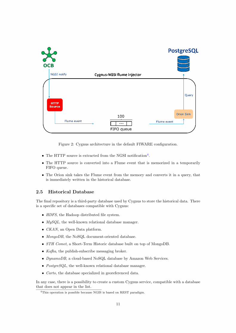
Figure 2: Cygnus architecture in the default FIWARE configuration.
� The HTTP source is extracted from the NGSI notification4.
� The HTTP source is converted into a Flume event that is memorized in a temporarilyFIFO queue.
� The Orion sink takes the Flume event from the memory and converts it in a query, thatis immediately written in the historical database.
2.5 Historical Database
The final repository is a third-party database used by Cygnus to store the historical data. Thereis a specific set of databases compatible with Cygnus:
� HDFS, the Hadoop distributed file system.
� MySQL, the well-known relational database manager.
� CKAN, an Open Data platform.
� MongoDB, the NoSQL document-oriented database.
� STH Comet, a Short-Term Historic database built on top of MongoDB.
� Kafka, the publish-subscribe messaging broker.
� DynamoDB, a cloud-based NoSQL database by Amazon Web Services.
� PostgreSQL, the well-known relational database manager.
� Carto, the database specialized in georeferenced data.
In any case, there is a possibility to create a custom Cygnus service, compatible with a databasethat does not appear in the list.
4This operation is possible because NGIS is based on REST paradigm.
11

2.6 Interaction of FIWARE components
Let’s now consider a FIWARE architecture composed by the elements in figure 3), where eachservice runs in a separated Docker container. The system initially requires a registration andconfiguration phase (1-2). Once configured, in the system the following interactions occur:
Figure 3: Basic interaction in a FIWARE system.
1. The first part of the configuration requires a set of cURL commands5 which are sent fromthe client. It contains two different information:
– The structure of the network and the IoT sensors.
– The subscription of Cygnus to the OCB notifications.
2. Data are converted into static context elements that are stored into the MongoDB.
3. A sensor node records a measurement and sends it to the IoT agent.
4. The IoT agent receives and converts the request in the appropriate format, as described inparagraph 2.3. At this point the IoT agent is not yet capable of creating a valid NGSI re-quest because it doesn’t known the data structure associated at this specific measurement.This information is therefore requested to MongoDB.
5. The IoT agent uses the data received from the MongoDB and the IoT agent, to build avalid NGSI request that contains the last measurement originating from the IoT sensor.
5cURL is a command-line tool used to create HTTP request for a specific URL.
12

6. The IoT agent sends the NGSI request to the OCB.
7. The OCB updates the context element, stored in the MongoDB database, with the lastmeasurement.
8. The OCB notifies the new measurement to Cygnus.
9. Cygnus inserts the new entries into the historical DB.
13

3 Implementation of FIWARE in the JRC site
In the first part of the report, I have described the functioning of the FIWARE system, withoutspecifying how to implement it in a real environment. Now, in the last part of this document,I will describe the specific configuration of such system for the testbed implementation at theJRC.
3.1 DMZ architecture
In a corporate network there is usually the need to have servers which offer public services to theexternal network (e.g. data visualization 5). If these servers are positioned inside the corporatenetwork, an attacker from the external network could exploit a vulnerability on the server togain access to the internal network. A possible solution is to connect such servers in a zonewhich is isolated from both the internal and the external network, called Demilitarized Zone(DMZ).
On the basis of the previous security requirements, we decided to implement the FIWAREplatform within a double demilitarized zone, protected by a four-legged firewall (see figure 4)that follows a whitelist approach:
1. The first DMZ is called “FIWARE DMRZ DC ”; it contains all FIWARE services imple-mented in two different VMs. This is the internal and more protected area of the archi-tecture, that will never be visible/accessible from the outside. The interactions betweenservices contained in the VM-A, follows the principles reported in paragraph 2.6.
2. The second DMZ is composed of two different zones:
– The “FIWARE DMZ DC ” zone contains the data visualization web application basedon Grafana interface (see paragraph 5 for more details).
– The “FIWARE DMZ CAMPUS”, a VLAN used to implement the gateway/IoT agentinteraction (see paragraph 4 for more details).
This zone is segregated from the internal JRC network, but still offering the possibility tointeract with the external network (restrictions apply).
All the interactions between the JRC network/DMRZ/DMZ/external network must be filteredby the firewall while, on the other hand, communications are direct within the same area.
The VM located in the internal JRC scientific network is used to manage via ssh all the FIWAREservices.
14

Figure 4: FIWARE implementation in the JRC.
3.2 Configuration of FIWARE services
All FIWARE services run in an isolated Docker container, located in one single virtual machine.In order to optimize the launch of all containers, I created a set of script files to manage theentire platform:
� fiware.sh, is the entry point of the configuration system. It accepts one argument in thecommand line:
– “start” → It launches the services from “docker-compose.yml” file.
– “load” → It launches the services from “docker-compose.yml” file; besides it uploadsall data entities and Cygnus subscriptions, through “import-data” and “sensors.sh”files.
– “stop” → It stops all the services contained in the “docker-compose.yml” file.
– “remove” → It stops all the services contained in the “docker-compose.yml” file. Itremoves also the container associated at FIWARE platform.
– “removeAll” → It stops all the services contained in the “docker-compose.yml” file.It removes also containers and images associated at FIWARE platform.
15

– “cleanAll” → It stops all the services contained in the “docker-compose.yml” file. Itremoves also containers, images and volumes associated at FIWARE platform.
� docker-compose.yml, contains the configuration of FIWARE services (see the paragraphs3.2.3, 3.2.4, 3.2.5, 3.2.6, 3.2.8 for more details).
� import-data, contains the cURL command used to configure the IoT network (see theparagraph 3.2.1 for more details).
� sensors.sh, contains the cURL commands used to configure:
– The token used by the IoT sensor in order to authenticate itself against the IoT agent.
– The IoT sensor structure (see the paragraph 3.2.1 for more details).
– The Cygnus subscription.
3.2.1 Data structure
The IoT network structure is contained in the “import-data” file:
{
"id":"urn:ngsi-ld:Gateway:LORD:MicroStrain",
"type":"Gateway",
"address":{
"type":"PostalAddress",
"value":{
...
}
},
"location":{
...
},
"number_of_sensors":{
"type":"Integer",
"value":"1"
},
"technology":{
"type":"String",
"value":"Wireless"
}
}
This is a static entity that, through the id “urn:ngsi-ld:Gateway:LORD:MicroStrain”, allows tocreate a reference to the other IoT sensors.
The only sensor registered in the system at this stage for testing purposes is configured asfollowing:
{
"device_id": "Node44023",
"entity_name": "Node:44023",
"entity_type": "accelerometer",
"protocol": "PDI-IoTA-UltraLight",
"timezone": "Europe/Berlin",
"attributes": [
16

{ "object_id": "t", "name":"timestamp", "type":"Integer" },
{ "object_id": "x", "name":"axisX", "type":"Float" },
{ "object_id": "y", "name":"axisY", "type":"Float" },
{ "object_id": "z", "name":"axisZ", "type":"Float" },
{ "object_id": "c", "name":"temperature", "type":"Float" }
],
"static_attributes": [
{ "name":"refGateway", "type":"Relationship",
"value":"urn:ngsi-ld:Gateway:LORD:MicroStrain"},
{ "name":"location", "type":"geo:json",
"value":{"type":"Point","coordinates":[45.812407, 8.629327]}}
]
}
This JSON structure is based on two static attributes that don’t change over time (referencegateway and geographic coordinates), and five dynamic attributes which depend on the sensormeasurements:
� Timestamp
� Axis X
� Axis Y
� Axis Z
� Temperature
3.2.2 Wireless Sensor Network components
The physical equipment used for the preliminary simulations are:
� G-Link LXRS Integrated Accelerometer Node [9].
� WSDA Base 101 LXRS Data Gateway [10].
3.2.3 Orion Context Broker
The configuration of the OCB service is:
orion:
image: fiware/orion:2.0.0
hostname: orion
container_name: fiware-orion
depends_on:
- postgres-db
networks:
- default
expose:
- "1026"
ports:
- "1026:1026"
command: -dbhost mongo-db -logLevel DEBUG
It uses the offical “fiware/orion” Docker image.
17

3.2.4 IoT Agent
The IoT agent that I decided to use in this architecture is the IoTAgent-UL (see the paragraph2.3 to see the list of available IoT agents). It is therefore necessary to implement a script inorder to convert IoT node data into the Ultralight format. The configuration of the IoT agentservice is as following:
iot-agent:
image: fiware/iotagent-ul:1.7.0
hostname: iot-agent
container_name: fiware-iot-agent
depends_on:
- mongo-db
networks:
- default
expose:
- "4041"
- "7896"
ports:
- "4041:4041"
- "7896:7896"
Such configuration uses the offical “fiware/iotagent-ul” Docker image and requires the followingenvironment variables:
� "IOTA_CB_HOST=orion"
The name of the OCB service in order to update the context entities.
� "IOTA_CB_PORT=1026"
The exposed port of the OCB.
� "IOTA_REGISTRY_TYPE=mongodb"
It defines the database name where the IoT device structure is memorized.
� "IOTA_MONGO_PORT=27017"
The exposed port of the MongoDB.
� "IOTA_PROVIDER_URL=http://iot-agent:4041"
The URL used to communicate with the IoT agent.
The IoT agent is also configured to accept only the requests that contain a valid token6. If thetoken is invalid or it is not present, the IoT sensor data are discarded.
6The value of token is set through a cURL command, contained in the “sensor.sh” configuration file.
18

3.2.5 MongoDB for the context information
The configuration of the mongoDB database is the following:
mongo-db:
image: mongo:3.6
hostname: mongo-db
container_name: db-mongo
ports:
- "27017:27017"
networks:
- default
command: --bind_ip_all --smallfiles
volumes:
- mongo-db:/data
It uses the offical “mongo” Docker image. The container is linked to a separated virtual volume(mongo-db:/data), that stores all the data.
3.2.6 Cygnus
The configuration of the Cygnus service is:
cygnus:
image: jrcfiware/cygnus-opt:latest
hostname: cygnus
container_name: fiware-cygnus
networks:
- default
depends_on:
- postgres-db
expose:
- "5080"
ports:
- "5050:5050"
- "5080:5080"
It requires some environment variables:
� "CYGNUS_POSTGRESQL_HOST=postgres-db"
The hostname of the PostgreSQL database used to persist historical context data.
� "CYGNUS_POSTGRESQL_PORT=5432"
It exposes the port of the PostgreSQL db.
� "CYGNUS_POSTGRESQL_USER=postgres"
"CYGNUS_POSTGRESQL_PASS=password"
The username and password for the PostgreSQL database user.
� "CYGNUS_SERVICE_PORT=5050"
19

Notification port where Cygnus listens when subscribing to context data changes.
The standard Cygnus service [8] is not designed to cope with high-rates acquisitions in real-time. However, this aspect is part of the testing campaign aiming at identifying constraints andchallenges of the system. For this reason, the Docker image used to create the Cygnus serviceis optimized in order to support real-time acquisition. The name of the custom Cygnus imageis “jrcfiware/cygnus-opt” and it is located in a private Docker Hub repository.
3.2.7 Cygnus optimization
There are different options to optimize the Cygnus service:
� The first one is to increase the capacity of the channel used by Cygnus to stop pendingrequests. The channel is designed as a FIFO queue7 that manages a list of pointers to theFlume events: the only operation that Cygnus performs on this structure is the iteration.For this reason, the use of a bigger channel doesn’t affect the Cygnus performance.
Nevertheless, this type of optimization is useful only if the notification throughput is notregular while, in real-time acquisition, it will only delay the occurrence of issues related tothe saturation of the channel.
� From a physical perspective, input/output operations per second (IOPS) are crucial; theuse of an SSD, instead of traditional disk, can improve the processing speed of collecteddata. The cost of an SSD storage can be expensive but there is also the possibility to usehybrid systems [11, 12, 13].
� The batch processing is the alternative approach used by Cygnus to process a set of OCBnotifications all together instead of one by one. With this approach, the Cygnus sinkcan aggregate different requests and therefore a single write operation is required. Thistype of processing is often associated with a timeout that stops the execution of all thepending requests contained in the batch queue being written into the DB (even if the limitof batching is not reached). In this way if, for example, the batch size is equal to 100 andthe OCB sends 99 NGSI notifications, Cygnus will be able to persist data in the databaseafter the expiration of the timer8.
By default the batch mechanism is not enabled:
<agent_name>.synks.<synk_name>.batch_size = 1
<agent_name>.synks.<synk_name>.batch_timeout = 30
Another problem is that, if Cygnus crashes (due to overhead), all data contained in thebatch queue are lost because Cygnus is not capable of persisting packets. A possiblesolution is to apply a retry mechanism (with the OCB service) composed by:
– A Time-To-Live (TTL) that specifies the number of retries that Cygnus will performbefore definitely dropping the event (0 means no retires, -1 means infinite retries).
– A list of retry intervals associated to the TTL variable.
� By default Cygnus uses a unique sink to process the NGSI notification but this can be abottleneck in some cases. To avoid such limitation, there is the possibility to add moresinks in two different situations:
7First In First Out behaviour.8Without the timer, the batch will never ready to be processed by Cygnus.
20

1. Multiple sinks, single channel - This type of configuration can potentially increasethe performance of the system but it creates also a competition between sinks. If theyare too fast to process event, this type of implementation can induce a significant lossof performance.
2. Multiple sinks, multiple channels - The problem mentioned above can be solved ina multiple channel system, where the competition for the single channel is avoided.However, this type of architecture requires a load balancing system to manage differ-ent sinks.
The “jrcfiware/Cygnus-opt” service uses the following configuration (see the figure 5), replicatedon a double sinks architecture:
...
cygnus-ngsi.sinks.postgresql-sink.batch_size = 100
cygnus-ngsi.sinks.postgresql-sink.batch_timeout = 30
cygnus-ngsi.sinks.postgresql-sink.batch_ttl = 10
...
cygnus-ngsi.channels.postgresql-channel.capacity = 1000
Figure 5: Cygnus architecture with improvements.
3.2.8 PostgreSQL for the data history
The configuration of the PostgreSQL database is:
postgres-db:
image: postgres:latest
21

hostname: postgres-db
container_name: db-postgres
expose:
- "5432"
ports:
- "5432:5432"
networks:
- default
environment:
- "POSTGRES_PASSWORD=<postgres_password>"
- "POSTGRES_USER=<postgres_user>"
- "POSTGRES_DB=<postgres_db>"
volumes:
- postgres-db:/var/lib/postgresql/data
It uses the official “postgres” Docker image. The container is linked to a separated virtualvolume (postgres-db:/var/lib/postgresql/data), that will be memorize the historical data.
22

4 Interaction between the gateway and the IoT agent
On the basis of the solution defined in the paragraph 2.3, I decided to implement the technique“b”. A python script is used to read in real-time the incoming data and convert them in theUltralight format. Finally, all the requests are aggregated into a single payload that it then sentvia ssh to the VM-A.
The python program and the gateway are located within the “FIWARE DMZ CAMPUS”VLAN.
4.1 The Ultralight 2.0 protocol
Ultralight 2.0 is a lightweight text based protocol developed for low-performance devices andcommunications where the bandwidth and device onboard memory are limited. The syntax isbased on a list of key-value pairs separated by the pipe character “|”; there is also the possibilityto aggregate more requests into the same payload with the “#” symbol.
t|1542698168001|x|0,03443152271|y|-0,0755809946|z|-0,9884393737|c|22,27757504#
t|1542698168009|x|0,04017862258|y|-0,08139494807|z|-0,9884393737|c|22,27757504#
t|1542698168017|x|0,02868442284|y|-0,0755809946|z|-0,9884393737|c|22,27757504#
t|1542698168025|x|0,03443152271|y|-0,0755809946|z|-0,9884393737|c|22,27757504#
t|1542698168033|x|0,04017862258|y|-0,06976704113|z|-0,982659027|c|22,27757504#
t|1542698168040|x|0,04017862258|y|-0,08139494807|z|-0,9768786803|c|22,27757504#
t|1542698168048|x|0,03443152271|y|-0,0755809946|z|-0,9768786803|c|22,27757504#
...
4.2 Python script
The script is developed in Python 2.7 and the following external libraries are used:
� sys, a mandatory library used to manage the principal python functions.
� mscl, that contains the APIs of LORD Microstrain [14].
� time and calendar, used to manage the timestamp (see below for details).
� paramiko used to create, manage and destroy the ssh connection.
The global variables are:
� COM PORT - The com port used by the gateway.
� NODE ADDRESS - The address of WSN.
� Max aggregation - The maximum aggregation of data (default value is 100).
� Command - It contains the header of command used to send data in Ultralight format.
The first part of the program establishes an ssh connection with the VM that contains the mainsystem: if the connection fails, an exception is raised and the program is terminated.
23

ssh = paramiko.SSHClient()
ssh.set_missing_host_key_policy(paramiko.AutoAddPolicy())
try:
ssh.connect(...)
except paramiko.SSHException:
print "Connection Failed"
quit()
If the connection is successfully established, the base station is configured through the MSCLlibrary:
� I create a serial connection with the specified COM Port (if the second argument is notinserted, the default baud rate is 921600).
connection = mscl.Connection.Serial(COM_PORT)
� I associate the base station to the connection.
baseStation = mscl.BaseStation(connection)
Before establishing the connection with the node, it is necessary to reset the base station inorder to create a new connection with a WSN.
baseStation.resetRadio()
Then, the creation of the node based on the address (global variable) and the base station isperformed:
node = mscl.WirelessNode(NODE_ADDRESS, baseStation)
A Wireless Node, when powered on, can be in one of the following statuses:
� Idle - The Node is awake and waiting for commands.
� Sleep - The Node is in a low power sleep status.
� Sampling - The Node is actively sampling or sending data.
If a Node is in the idle status, it will respond to pings, can be configured, and can be put intothe other statuses (sleep or sampling). On the other hand, if a Node is in the sleep status orsampling status, it cannot be direct communicated with the Node is not possible. In order tocommunicate with the Node, this must be put back into the idle status. This is done with thecommand setToIdle():
idleStatus = node.setToIdle()
Now, the node can execute a ping to verify the connectivity with the base station. If a reply isreceived, it means that the network was successfully created:
network = mscl.SyncSamplingNetwork(baseStation)
network.addNode(node)
Once the network is established, the data acquisition can be activated,
network.startSampling();
24

I use an infinite loop in order to read all the data.
# get all of the data sweeps that have been collected by the BaseStation,
with a timeout of 500 milliseconds
sweeps = baseStation.getData(500)
for sweep in sweeps:
For each data contained in the sweep variable, the following actions are performed:
� The acquisition timestamp is retrieved:
date_str = str(sweep.timestamp())
Then, it must be converted to a float timestamp:
date = date_str[:19]
time_tuple = time.strptime(date, "%Y-%m-%d %H:%M:%S")
#time tuple to timestamp format
timestamp=calendar.timegm(time_tuple)
#now we have the timestamp in second. It is necessary transform it in
millisecond and than add the .\%f remaining ones.
ts_int = int(timestamp)
ts_int*=1000
fff=int(date_str[20:23])
ts_int+=fff #final_timestamp
Finally the timestamp is added to the “to send” variable.
to_send += "t|" + str(ts_int) + "|x|"
� At this point, all the values contained in the 4 channels are read.
for dataPoint in sweep.data():
There are now 4 cases depending on the sensor node channel being processed:
– The data belongs to the first channel.
if dataPoint.channelName() == "ch1":
val_raw = dataPoint.as_float()
val_fin = val_raw*0.005747
val_fin = val_fin-11.20689
to_send += str(val_fin) + "|y|"
– The data belongs to the second channel.
elif dataPoint.channelName() == "ch2":
val_raw = dataPoint.as_float()
val_fin = val_raw*0.005813
val_fin = val_fin-11.56976
to_send += str(val_fin) + "|z|"
25

– The data belongs to the third channel.
elif dataPoint.channelName() == "ch3":
val_raw = dataPoint.as_float()
val_fin = val_raw*0.00578
val_fin = val_fin-11.39884
to_send += str(val_fin) + "|c|"
– The data belongs to the fourth channel.
elif dataPoint.channelName() == "ch4":
val_raw = dataPoint.as_float()
val_fin = val_raw*0.117188
val_fin = val_fin-67.83999
to_send += str(val_fin)
if i < max_aggregation:
to_send+="#"
In this case, the temperature value represents the last element of the packet. If thecurrent index is less than the maximum aggregation limit, it is necessary to insert a“#” symbol in order to split separated elements.
If the limit of maximum aggregation is reached, the command ssh is prepared:
payload = "’" + to_send + "’"
ssh.exec_command(command + payload)
Otherwise the “i” variable is increased.
26

5 Grafana
Grafana [15] is an open source visualization tool that can be used to visualize data residing ondifferent storage backends. It is composed by a set of plugins that users can use in order tocreate a feature-rich custom dashboard.
Figure 6: JRC FIWARE GUI loging page.
In our implementation, the Grafana system has been installed on the VM-B virtual machine,within the “FIWARE DMZ DC ”. At the moment, there are only two ways to access the Grafanaweb application:
� From scientific network, the service can be reached through
http://<vm-b_IP_address>:<vm-b_port>
� From the corporate network NET1, the service can be reached through
http://<reverse-proxy_IP_address>
In the last case, a reverse-proxy server is used in order to protect the original server whereGrafana is running.
27

Figure 7: JRC FIWARE: wireless sensor nodes and base details page with geographical position.
Figure 8: Accelerometer acquisition visualization page.
28

Figure 9: Multiple axes details visualization of accelerometer wireless node.
Figure 10: JRC FIWARE acquired data listing.
29

6 Future enhancements
The initial architecture of the JRC implementation of the FIWARE system will be improvedtowards better performance. I am going to explain here some of the improvements that will beintroduced in the future release of the system.
Figure 11: FIWARE implementation with improvements.
6.1 Custom IoT agent
The FIWARE architecture envisages the possibility to introduce different IoT networks. In thiscase, it is necessary (see 2.3 for more details) to associate each new WSN to a dedicated IoTagent service.
6.2 VM-C
The PostgreSQL database can cause slowdowns for Cygnus and Grafana services. In order torelieve the load from the DB, a distributed databases environment can be adopted:
30

� The PostgreSQL DB in VM-A is used to memorize temporarily the data collected byCygnus.
� A new VM (VM-C in figure 11) will be used to store all the historical data9.
6.3 Security in the IoT network
Security is a key aspect in IoT networks, in order to avoid that a possible MITM attack couldeavesdrop or modify the communication between the sensor and the associated gateway. Thereare three rules to be observed during data transmission:
� Non repudiation: a security system offers the non-repudiation property if it allows tocreate a formal proof, acceptable by a court of justices that gives undeniable evidence ofthe data creator.
� Confidentiality : a security system offers the confidentiality property if it allows to guar-antee that no one can access confidential information without being authorized.
� Integrity : a security system offers the integrity property if it allows to check if data hasbeen manipulated, through the following techniques:
1. modification
2. cancellation
3. replay10
In order to address such concerns, I have elaborated the following architecture (see the figure12), assuming that the negotiation of cryptographic keys used during the session has alreadybeen performed.
Figure 12: Security interaction between a sensor and the gateway, in an IoT network.
For each data sent, at the level of the sensor node the following tasks are performed:
9You can also use a different database strategy through, for example, a Big Data implementation.10Data in transit could be copied and transmitted more times.
31

a. The sensor associates an internal counter to each packet in order to be able to identify theframe. If a sensor already uses a timestamp by default, this step is not needed.
b. The sensor applies a hash function to the couple “[counter + datagram]” in order to obtaina message digest: it will be used to satisfy the integrity property during data transport.
c. The digest is encrypted, via the private key of the sensor node, to obtain the digitalsignature; this allows to ensure the non repudiation property of the resource.
d. The data triplet of data “[counter + datagram + digital signature]” is then encryptedthrough a symmetric encryption algorithm (shared with the gateway): in this way, theconfidentially property is ensured. In terms of cybersecurity, the best compromise is theAES-256-CBC algorithm [16, 17].
e. Finally, the datagram is sent and the sensor waits for an acknowledge response. If anACK signal is not received before the predefined expiring, the frame is sent back. Thismechanism is necessary to avoid jamming problems.
At the gateway, for each data received the following actions are performed:
� The gateway uses the symmetric encryption key to obtain the clear datagram.
� Then, the string that identify the sensor is read: in this way the public key and the counterassociated with it are derived.
� If the counter contained in the datagram received is less than or equal to the other counter,the whole data is dropped (because there could be a replay attack). Otherwise, thedatagram is considered valid and the counter in the file is updated.
� The hash function is not invertible and, for this reason, it is not possible to obtain thecouple “[counter + datagram]” from the digital signature. The only operation permittedto verify the integrity of datagram is:
– Application of the hash function to “[counter + datagram]” in order to produce adigest.
– Decryption of the original digital signature with the sensor node’s public key toobtain, in this way, the digest product from datagram.
If the comparison between the digest calculated and the original digest is positive, theintegrity property is satisfied. Otherwise the datagram is dropped.
� After checking all the security properties, the gateway sends the acknowledge responseat the sensor. If the ACK is lost during the transmission, the sensor will send again thedatagram which will be dropped by the gateway. In this case, the gateway would transmitagain the ACK. Generally, this type of situation is equivalent to a temporary local failurethat converges automatically to a stable solution.
The approach explained in this paragraph is the best implementation in terms of security, butit may cause a too high energy consumption for an IoT sensor. Moreover, in order to guaranteea proper functioning of the system, it would be necessary that all the keys used are stored in asecurity safe place11
11Possibly in a different place from that used by devices.
32

6.4 Security in the FIWARE system
The application security of the FIWARE platform is not yet implemented in the JRC currentpreliminary implementation12. Each user could have access to each service residing in the VM-A, without any restrictions. To limit and control users access it is necessary to introduce anauthentication and authorization system.
6.4.1 Authentication system
Keyrock [18] is an authentication system (part of the FIWARE project) based on traditionalusername/password. Even if this type of system is not the most advanced implementation interms of security and usability, it can still be considered a good mechanism because it integratesseamlessly with the FIWARE architecture. Keyrock requires a SQL database to store theencrypted user credentials.
6.4.2 Authorization system
In order to prevent all authenticated users from having full privileges on the FIWARE systemand collected data, it would be advisable to introduce an authorization system. A possiblesolution is XACML, a language used to evaluate access requests according to the rules definedin the policy. In the article “Evaluating the FIWARE Platform” [19] a possible implementationof XACML mechanism within the FIWARE architecture is explained. It involves three differentcomponents:
� The Identity Manager (IdM), allows the definition of different policies for users or groups.
� The Policy Decision Point (PDP) which, on the basis of the policy evaluation, can denyor authorize the action of the user on a specific resource.
� The Policy Enforcement Point (PEP), an intermediary between user and PDP.
In figure 13 the interactions between these services are shown. After having verified the accesstoken validity with the IdM, the PEP sends a request containing user details to the PDP.The PDP retrieves the policy associated with the user and generates a response (positive ornegative) then transmitted to the PEP. The language used between PEP and PDP is XACMLwhile the IdM only accepts HTTP messages. The translation from XACML to HTTP is doneautomatically by the system.
12If the security and network limitations are ignored.
33

Figure 13: Interaction scheme between PEP, PDP and IdM.
34

References
[1] “Overall FIWARE Vision.” https://forge.fiware.org/plugins/mediawiki/wiki/
fiware/index.php/Overall_FI-WARE_Vision
[2] “Context Broker joins CEF.” https://ec.europa.eu/cefdigital/wiki/display/
CEFDIGITAL/2018/11/12/Context+Broker+joins+CEF
[3] “Docker.” https://www.docker.com/
[4] W. Felter, A. Ferreira, R. Rajamony, and J. Rubio, “An updated performance compar-ison of virtual machines and linux containers”, 2015 IEEE International Symposium onPerformance Analysis of Systems and Software (ISPASS), March 2015, pp. 171–172, DOI10.1109/ISPASS.2015.7095802
[5] “Orion Context Broker - Fiware.” https://github.com/telefonicaid/fiware-orion/
[6] “MongoDB.” https://www.mongodb.com/
[7] “IoT agent - Fiware.” https://github.com/telefonicaid/iotagent-ul
[8] “Cygnus.” https://github.com/telefonicaid/fiware-cygnus
[9] “G-Link LXRS Low-cost Integrated Accelerometer Node.” https://www.microstrain.
com/wireless/g-link
[10] “WSDA Base 101 LXRS Data Gateway.” https://www.microstrain.com/wireless/
wsda-base-analog
[11] X. Zhang, K. Davis, and S. Jiang, “itransformer: Using ssd to improve disk scheduling forhigh-performance i/o”, 2012 IEEE 26th International Parallel and Distributed ProcessingSymposium, May 2012, pp. 715–726, DOI 10.1109/IPDPS.2012.70
[12] S. Qiu and A. L. N. Reddy, “Nvmfs: A hybrid file system for improving random write innand-flash ssd”, 2013 IEEE 29th Symposium on Mass Storage Systems and Technologies(MSST), May 2013, pp. 1–5, DOI 10.1109/MSST.2013.6558434
[13] H. Jo, Y. Kwon, H. Kim, E. Seo, J. Lee, and S. Maeng, “Ssd-hdd-hybrid virtual disk inconsolidated environments”, Euro-Par 2009 – Parallel Processing Workshops (H.-X. Lin,M. Alexander, M. Forsell, A. Knupfer, R. Prodan, L. Sousa, and A. Streit, eds.), Berlin,Heidelberg, 2010, pp. 375–384
[14] “LORD-MicroStrain MSCL.” https://github.com/LORD-MicroStrain/MSCL
[15] “Grafana.” https://grafana.com/
[16] S. K. S. Frankel, R. Glenn, “The AES-CBC Cipher Algorithm and Its Use with IPsec”,September 2003, DOI 10.17487/RFC3602
[17] K. M. U. Blumenthal, F. Maino, “The Advanced Encryption Standard (AES) Cipher Al-gorithm in the SNMP User-based Security Model”, June 2004, DOI 10.17487/RFC3826
[18] “Keyrock.” https://github.com/ging/fiware-idm
[19] P. Salhofer, “Evaluating the FIWARE Platform: A Case-Study on Implementing SmartApplication with FIWARE”, January 2018, DOI 10.24251/HICSS.2018.726
35

GETTING IN TOUCH WITH THE EU
In person
All over the European Union there are hundreds of Europe Direct information centres. You can find the address of the centre nearest you at: https://europa.eu/european-union/contact_en
On the phone or by email
Europe Direct is a service that answers your questions about the European Union. You can contact this service:
- by freephone: 00 800 6 7 8 9 10 11 (certain operators may charge for these calls),
- at the following standard number: +32 22999696, or
- by electronic mail via: https://europa.eu/european-union/contact_en
FINDING INFORMATION ABOUT THE EU
Online
Information about the European Union in all the official languages of the EU is available on the Europa website at: https://europa.eu/european-union/index_en
EU publications
You can download or order free and priced EU publications from EU Bookshop at: https://publications.europa.eu/en/publications. Multiple copies of free publications may be obtained by contacting Europe Direct or your local information centre (see https://europa.eu/european-union/contact_en).

KJ-N
A-3
00
38
-EN-N
doi:10.2760/314017 ISBN 978-92-76-14658-2
Related Documents


