A. J. ACOSTA Mem. ASME T. KICENIUK Mem. ASME E. R. BATE, JR. Hydrodynamics Laboratory, K6rm6n laborato ry of fluid Mechanics and Jet Propulsion, California Institute of Technology, Pasadena, Calif. Introduction Measurements on Fully Wetted and Ventilated Ring Wing Hydrofoils Force measurements and visual observations were made in n water tun1tel 011 fully wetted and ventilated flows past a family of conical ring wings having a flat plate section geometry. The diameter-chord ratio was varied from one to three, at a fixed total in- cluded cone angle of 12 deg. The fully welted flows all exhibited separation from the leading edge except for the largest diameter-chord ratio, a result which has been at- tributed to excessive cone angle. The effect of ventilation is to reduce markedly the lift curve slope. Pressure distribution measurements were also made under ventilating conditions for one member of this series. The effect of ventilation over only a portion of the circumference of the ring was also briefly investigated; large cross forces were de- !leloped by such ventilation. T HE GBNERAL characteristics of ring wings in uni- form fl ow are well known, having found app lication in marine propellers, aircraft, torpedoes, and depth bombs. The func- tion and description of many of these applications are to be found in references [J and 2], 1 while tho general theoretieal ba<·kground of ring wings is d ealt with in refe ren ces [2 through 10]. which may augment or replace altogether t he conventional rud- ders found on s hips or torpedoes. The possibility of such an app li cation was originally suggested by Smith and later followed up in the work of La ng and Dayboll [11] in water tunnel tests earried out at t he California Institute of Technology on two- dimensional hydrofoils with controlled air ventilation. Description of Apparatus and Experimental Technique All of tho forrgoing references and a ppli cations deal with full y wetted fl ow; t hat is, tho sur rounding fluid is eil her all liquid or all a ir. Because of the proximity of a nPighhoring frpe in a flow of liquid, or JWrhaps as a of ll1f' dPiilwraiP injPetion of gas into a liquid flow, a two-ph'"'" f1ow may tnke pla<·P. Th<· ob- ject of til(' prcsPnt work is to sln dy :tnd to tn•at !'XIH'rimPIIIally some of lhc problems a.,S<H'iaiPd with lh<• usc of supt-l'VPIIlilaling and partly venti lating ring The information thus gained may be usef ul for rlPvising now sc hemps of din•rl ion eont rol Fac ility Descri ption. The expe rimental work described in this paper was performed in the H ydrodynamics Laboratory at the California Instit ute of Technology using tho free-surface water tunnel. l{cfcr('nce [12] deKeribcs in some d etail the facilities of the laboratory and, in partic·ular, the operation of t.he free-sur- face water tunne l. In the first lest I he were made of the tota l forces acting on eompletc ring n.ssemhlies. To accomplish t his, thP rin g models were held by a strut, which, in turn, was s upported by a strai n-gage balanec, Figs. 1, 2. The balance was rigidl y attached to "ground" above the water surface and the s upport str ut held the model s ubmPrged in the flow. The ob- jective of t he second sPries of was to determine the pressure acting at various points on the model. A complete series of such measurements would yield t.he total pressure distribution on the 1 Numbers in brackets designate Jtcfercnces at end of paper Contributed by the Underwater Technology Division and presented at the \Vinter Annual Meeting, New York, . Y., November 27- December 1, 1966, of THE AMEJHCAN SoCIETY OF l\IECHANICAL ENGI- NEERS. l\1anuscript received at AS:\TE Headquarters, .June 16, 1966. Paper No. 66 - WA/UnT-4. ----Nomenclature----------------------------- ;1 c CLa area, tota l wetted area of vell- tilating models, one-half wet- ted area of fu ll y wetted models mode l chord (measured along eone genNator) drag coefficient, _ _ D __ l/2pY 2 A J .f 1r· · L 1 t coe JCJent., ---- l /2pY2.1 rate of change of lift coefficient with a ngle of attack . ,1/ momentcoefliCJent, -- ---- 1 /2 plT2A (2r1) normal force coefficient, n ,[ l /2pY 2 - 27r pressure roeflicien t, p - Pm L /2 pV' airflow rate coefficient, Journal of Engineering for Industry ]) " F k n p Q 7r(r1' - r 2 2 )Y total drag force dept h of model center line from water surface Froudc number, vI v · 2gr, V!'nt ilation number, Pm - Pt, 1/2pY. also call ed cavitat i on number tota l lift force pitching moment about, ring leading edge normal force perpendicular to st u·fa<'e of conical ring per unit polar angle stat ic pressure measured at, an.v point of body cav ity pressure free-stream pressure far up- stream of the model center linP Q r rl 1'2 2rt!c v X a r e p quantity of ventilating gas sup- plied at ambient pressure in the cavity rad ius measured to any point on the model measured from the model <'rnter l ine radius at e ntrance of ring radius at ex it of ring model aspect ratio velocity distance of pressure tap location from leading edge of model angle of attack of force model hound c irculati on about chord of ring profile half-cone angle of coui cal models, 6 dog polar ang le measnred positive clockwise looking downstream from water s urface water dens it y A u G u s T 1 9 6 7 I 445

Welcome message from author
This document is posted to help you gain knowledge. Please leave a comment to let me know what you think about it! Share it to your friends and learn new things together.
Transcript
A. J. ACOSTA Mem. ASME
T. KICENIUK Mem. ASME
E. R. BATE, JR. Hydrodynamics Laboratory,
K6rm6n laboratory of fluid Mechanics and Jet Propulsion,
California Institute of Technology, Pasadena, Calif.
Introduction
Measurements on Fully Wetted and Ventilated Ring Wing Hydrofoils Force measurements and visual observations were made in n water tun1tel 011 fully wetted and ventilated flows past a family of conical ring wings having a flat plate section geometry. The diameter-chord ratio was varied from one to three, at a fixed total included cone angle of 12 deg. The fully welted flows all exhibited separation from the leading edge except for the largest diameter-chord ratio, a result which has been attributed to excessive cone angle. The effect of ventilation is to reduce markedly the lift curve slope. Pressure distribution measurements were also made under ventilating conditions for one member of this series. The effect of ventilation over only a portion of the circumference of the ring was also briefly investigated; large cross forces were de!leloped by such ventilation.
THE GBNERAL characteristics of ring wings in uniform fl ow are well known, having found application in marine propellers, aircraft, torpedoes, and depth bombs. The function and description of many of these applications are to be found in references [J and 2], 1 while tho general theoretieal ba<·kground of ring wings is dealt with in refe ren ces [2 through 10].
which may augment or replace altogether the conventional rudders found on ships or torpedoes. The possibility of such an application was originally suggested by Smith and later followed up in the work of L a ng and Dayboll [11] in water tunnel tests earried out at t he California Institute of Technology on twodimensional hydrofoils with controlled air ventilation.
Description of Apparatus and Experimental Technique All of tho forrgoing references and applications deal with full y wetted flow; t hat is, tho surrounding fluid is eil her all liquid or all a ir. Because of the proximity of a nPighhoring frpe ~urfaco in a flow of liquid, or JWrhaps as a re~•Jit of ll1f' dPiilwraiP injPetion of gas into a liquid flow, a two-ph'"'" f1ow may tnke pla<·P. Th<· object of til(' prcsPnt work is to slndy :tnd to tn•at !'XIH'rimPIIIally some of lhc problems a.,S<H'iaiPd with l h<• usc of supt-l'VPIIlilaling and partly ventilating ring wing~. The information thus gained may be useful for rlPvising now schemps of din•rl ion eontrol
Fac ility Description. The experimental work described in this paper was performed in the H ydrodynamics Laboratory at the California Institute of Technology using tho free-surface water tunnel. l{cfcr('nce [12] deKeribcs in some detail the facilities of the laboratory and, in partic·ular, the operation of t.he free-surface water tunnel.
In the first lest :seril'~, I he JUl'>L~urcmcnt,; were made of the total forces acting on eompletc ring n.ssemhlies. T o accomplish t his, thP ring models were held by a strut, which, in turn, was s upported by a strain-gage balanec, Figs. 1, 2. The balance was rigidly attached to "ground" above the water surface and the s upport strut held the model s ubmPrged in the flow. The objective of t he second sPries of te.~ts was to determine the pressure acting at various points on the model. A complete series of such measurements would yield t.he total pressure distribution on the
1 Numbers in brackets designate Jtcfercnces at end of paper Contributed by the Underwater Technology Division and presented
at the \Vinter Annual Meeting, New York, . Y., November 27-December 1, 1966, of THE AMEJHCAN SoCIETY OF l\IECHANICAL ENGINEERS. l\1anuscript received at AS:\TE Headquarters, .June 16, 1966. Paper No. 66 - WA/UnT-4.
----Nomenclature-----------------------------; 1
c
CLa
area, total wetted area of velltilating models, one-half wetted area of fu lly wetted models
model chord (measured along eone genNator)
drag coefficient, _ _ D __ l/2pY2A
J.f 1r· · L 1 t coe JCJent., ----l /2pY2.1
rate of change of lif t coefficient with a ngle of attack
. ,1/ momentcoefliCJent, ------
1/2plT2A (2r1) normal force coefficient,
n , [
l /2pY2-27r
pressure roeflicient, p - Pm L/2pV'
airflow rate coefficient,
Journal of Engineering for Industry
])
" F
k
n
p
Q 7r(r1' - r 2
2)Y
total drag force
depth of model center line from water surface
Froudc number, vI v ·2gr,
V!'nt ilation number, Pm - Pt, 1/2pY.
also called cavitation number
total lift force pitching moment about, ring
leading edge normal force perpendicular to
stu·fa<'e of conical ring per unit polar angle
static pressure measured at, an.v point of body
cavity pressure free-stream pressure far up
stream of t he model center linP
Q
r
rl
1'2 2rt!c
v X
a r
e
p
quantity of ventilating gas supplied at ambient pressure in
the cavity rad ius measured to a ny point on
the model measured from the
model <'rnter line radius at entrance of ring radius at ex it of ring
model aspect ratio velocity distance of pressure tap location
from leading edge of model angle of attack of force model hound circulation about chord
of ring profi le half-cone a ngle of couical models,
6 dog polar angle measnred positive
clockwise looking downstream from water surface
water d ens ity
A u G u s T 1 9 6 7 I 445

f ig. 1 Forces on r ing wing showing sign convention and th e force· m ea suring apparatus
Fig. 2 Fully ventilated ring wing. The chord is 3 in. and the diameter 6 in. The cavitation number is 0 .13 and the angl e of attack is 0 deg.
model. To accomplish this, a rigid metal p late was mounted at the plane of the water surface. The surfa<"<' of this plate provided a plane of symmetry for the flow and was henre called a " reflection" plane. In this way, the free-surface water tunnel was conv<'rlcd into a dosed jet tunnel having a working section approximately 20 in. sq, Figs. 3, 4. The mod<'l in this case consis ted of a half ring projecting through t he rdlcetion plane.
Cavity pr<'SStn'<'S were measured using a water manometer connected to a small hole drilled in the side of t he mod<'l which communicated to the cavity. Air was bkd s lowly t.hrougb the cavity pressure- m<'asuring lines to insure that t.hcy would be free from water. This airflow resulted in a small zero ofT e t in the cavity pressure rf'adings which was accounted for in the data reduction process. The main cavity air supply mt.c was measured using a Fisher-Porter flowmeter and reduced to ambient conditions by applying the proper corrections for line p ressure a nd tempcrat.ure. The forces acting on the models were meas ured with a T ask Corporation six-component e lectrical strain-gage balance and displayf'd on an integrating digital voltmeter. Individual pressure transducers were used to meas ure the pressure distribution, and t he outputs of these pr<'ssurc transduc<'rs were a lso monitored by the digital voltmeter.
446 I AuGusT 1 9 6 7
To d<'lermint• the pre~snn• <·oefli <' i ellt~ from the measun·menl,; llHlO<' with th!' prP><>'<U r(' dist rihn t ion modf'l , a d!'tailpd knowlcdg<• of t lw flow in thp vi<·init1· of th<' modPI was nccPssary. Both thP houndary-lay<'r t hi<"knf's~ and lh<• flow dire<"tion at t he refl pclion plane rwar lh<' model mounting location were measurPd. These surveys revt'aled that thr l)()nndary layer in the vi!'inity of lhP model is approximatf'ly 1/ 4 in. thick and the flow deviat ion over the intercepted radins of lhP modPI i" approximately 0.7 deg.
Model Description. Bdore de<·iding upon the final configuration of tht' ring modpl, it was t honght advisnble to perform a ~erie~ of pr<.'liminary dPsign l'Xp(•rinwnls which would help decide que:;tions of model si7.e and gponwlry, both in the fully welled and cavitating flow regimes. In addition, the proposed system for supplying air to the model in lh<' cavitating case could be studied.
Sevt'ral important ronsidPrat ions di<'tated t he ('hOi<'f' of model se!'lion:
(a) BP<·ausp of tlw exploratory natnrc of the,.,e t•xperimenls, the modt'l should I><' Pl\~.v to fahri ('atP so that various model s izes, aspect ratios, and so on, mny !Jp readily s tudied.
(b) The model should hP able to operate fully w<•t ted and fully vt'nlilatt'd, a.~ wpll as par t ia lly ventilated, wi thout <·hanging its efTeclivP gPomelry ; i.e., con<' angle, camber, or atlaehment point, of eavity.
(c) The rpsult~ should he amenable to comparisons wi t h theory and past expl'rinwn ls, holh to those pertaining to ring wings and to two-d imensional a irfoi ls.
F or llll'Se rPasons, l h(• t,pst model was construeted in lhP form of a cone having a lola! indudPd a ngle of 12 deg, as a cone is llw s imples t eonfiguration that provides a normal force in axi~ymmetri r flow. The sect ion profile consisted of a 1 / 8-in-lhick fla t pial<' with n rotuHil'd spmiC'ir"ular nose and blun t. trailing edge. Air was suppliPd to I hP ('avity by means of a small s lit approximately O.OO.'i in . widr, mal'hinpd in the brass model on t he s uction side a t. lhe point of tangt'IH'Y het wf'pn the ('ylindri('allt'ading edge and l he flat ,;urfa<·p, Fig . .'i. The sli t, was connect ed to a plenum l'hnmber ma!'hined into the fl:tt plate section a nd lo thp labor·atory air supply by tuht's whi<·h ran up the in-ide of the hollow suppor t strut.
The upstt·pam, or inlt'l, diameter of the cone wa.s fixPd at 6 in. for hot h the fon·c model in Fig. 2 and the pressure dis tribution " half model" in Fig. 4. T o investigate the efTect of C'hanges in model chorcl, t he for<'P m odel was constructed of a main ring and a series of trailing edge adapter rings, Fig. 5, resulting in m odels of 2, 3, 4, and 6-in. chord. The pressure distribution mod€'1 wa.~ fabri('atPd in t.hP :3-in. chord s ize only.
A cylindrical model having a 3- in. chord and without provisions for a ir vpnli lation was also made for mt'asuring t hP forc<:'S under fully welled ('Onditions.
Force Measurements. The for('es a!'ling on the ring models were measured us ing lhP ~train-gage balance. The model-strut assembly is alta('hcd to the fon·e balance, which i~, in turn, supported hy the anglP-dlanging mPchanism with rotation taking place about a <·pnler a rrangPd to <·oinc·ide with t he renter line of the model. ~ince the balan('c rotal<'s with the model, t he forces a rc measured with rl'spe<· t to t he model axes. These forces arc subsequent.ly rpfprrpd to a~ axes parallel to t he undistnrht'd flow upstream.
Although thC' strain-gage hahuH'<' is capable of measuring si..x force compont'nts, only thosP ne<"essary to determine lif t, drag, and pit.ching momPn t were actually taken as datn ; the other t.hree were only monit.ored lo insure proper yaw alignment..
For t.he case of thP cavilat.ing models, the cavity air s upply was d('lerminPd for each configuration that would give a fully develop('(! cav ity over the entire range of a ngles of attack. The air supply rate was tlw n rpadj us led to t his constant value before eaeh data poin t wa., tak<•n. The cavity pres·urc was mpasured a nd t he variation in cavitation number al constant a ir supply for each of the t<'sl conditions is shown in Fig. 6. For the pressure distribution tC'sts, air supply was not measured hut cavity
Transactions of the AS ME

I RFf- LE.CT ION PlANE
~a ~CTION
PRESSURE TAP RO W
Fig . 3 Pressure distribution model schematic, defining the pertinent parameters and sign conventions
Fig. 4 Reflection plane mounted pressure distribution model. Chord is 3 in., lc = 0 .1 0, angle of yaw is 4 d eg . Flow v e locity is 18.6 Ips.
pressme wa:; taken ~~~data. II ere, two di~tinet value"' of cavitation number were obtained. One oecmred when th<' cavity l<'nglh was adjusted to approximately three body dia, and the other occurred when the cavity wa.~ allowed to grow until it extended beyond the plate and opened to the atmosphere, through the free "'urface. In t he formC'r ca.~e the cavitation numbers obtained werC' on the order of k - 0.10, and in the latter C"ase they were a pproximately k = 0.01.
To minimize any possible interfcren<·c• between the model supporting strut and the r ing wing itself, it was necessary to keep the thickness of t he• s trut at, an absolute minimum consistent with the requirement~ of st rength and the geometrical armn11:ement of the l ubes whieh supplied the ring with ventilating a ir a nd measured the cavity pr!'ssure. The presc•n t strut wa.~ made by an !'lel'troforming proc·('ss in which nickel wa,.; depoRiled over a mandrel fa.~hioncd of a low-meltin!!:-POinl alloy. The mandrl'l whieh was ~uhsequC'nlly melted out inc·orpomted all the nc•c·pssary tubes and mounting fixtures.
Pressure Dis tribution Measurement. f n ordC'r to obtain dPiailed information about the local fore<' c·oeflieients on the ring wing in both cavitating and fu lly wetted flow, a prC'SsUr<' distribution model was employed with whieh the pressure at an~· de., ired location on both the pressure and suction surfac·e.~ of t he model eould hp measured. For t he purpo~e of this seric,.; of te.~ls, the reflcet ion plane previou,..l_,. mentioned wa:s in~ta lled at the watcl' surface in the free-surfac·c waicl' tunnel. The modpl wm; sPi in a mounting disk which, in turn, was itself placed in a large cirrub,. hole in t hE' reflection plane . The lowe,. surf are of the mounting disk was
Journal of Engineering for Industry
'-======
'- 2 IN CHORD MAIN RING
' I IN CHORD EXTENSION RING
TRAILING EDGE FILLER RING
HOLLOW SUPPORT STRUT
p CI RCUMFERENTIAL AIR DISTRI B UTION PLENU M
Fig. 5 Sketch showing assembly ring w ings and the ventilation slot at the leading edge
0 u
0.40
w 0.35 ... <t a: 3: ~ 0.30
a: <t
0 0.25 2 <t
0.20 a: "' <D :> ::> z 0.15
z 0 ... <t ...,_ 0.1 > <t u
0
0.0 5
01 - 4
0
0 0
l Co
0 0 u 0
Kl 0 "' 0
-=--v ~-v
"' 0
0
" - 0
ANGLE OF AT TACK, a ( OEG)
n
J I
--t
0
J ~
J'>. _,.,_
~ - 3 ~ •2
2 '• • 1.5 c ~ •I c
4
Fig. 6 Variation of measured cavitation (ventilation) number at fixed clir supply rates for conical ring wings at varying aspect ratios
Au G u sT 1 9 6 7 I 447

coincident with that of Lhe reflection planP, Fig. -L The disk could he Lumed about a vertical axis, thC'r<'h.v .\':twin~ the model with rCHpecL lo lhe oneoming flow. Bt•ralh(' of s.\"lnmet.ry, thi.-3 was equivalent lo v:u·_,·inl-( lhC' anv;l<' of atl<~ck of a complete ring . .-\ row of 11 prc~HHrP taps wa.~ drilled 011 hut h the prPS.~ure and suttion Rurfaces of the model in a chordwi.~e dire("{ ion. These holes rurnmunirated lo a corresponding numbc•r of 1/ 16-in-dia brass Lube.~ which were placed eircumfenmli:tll.\• in slots LurnE'd in the surfacE' of the model. The .. ~e t uhes hroke out of the surfa<·e of thE' rnod!'l for subsequent attachment to lim•:; lcadinll: Lo the prCHSIIrE' measuring transdu<"ers at a point appmximately 150 de~ around the ring from the location of Uw pressure Laps. The chordwise pressure distributions were oblaint>d direcUy by measuring the pressures at each of the different tap locations and the variation of pressure as a function of polar angle (or "span wise" variation) could be determined by rotating Uw model about it.~ e·entral axis in Lhc mounting disk which was set in the reflection plane. The pressure taps, however, eould on!_,. he rotated from 0 120-deg polar angle. Prc~sure distributions amund t he complete ring were obtained when it was yawE'd hy performing part of the measurements (0 90 deg) at a positive yaw angle and the remainder (90-180 deg) with a negative yaw angle. Fig. :~ shows Lhe geometr.\' of lhe pressure distribution model in schematicfonn.
Prior experiments performed on the complete ring; used in the forcemeasuremenLs indicated thatafully ventilated condition <'Ould be mainl:tined without us ing the leading edge slot but with the use of an auxi liary air supply, a lthough injection of air Lhrou~h a leading edge slot was generally required to initiate ventilation. Because of the comparative complexity of the pn•ssure lap model, the leading edge vPntilalion slot was omitted and ventilation was initiated b.\' imparting large yaw ang;IPs to the model. Once started, t he vpnlilation rou ld be maintained through small aic· supply ports in the image plate located ncar the trailing edge of the ring even Lh<Hlll:h lhe an~le of yaw of the ring was subsequently reduced.
Tunnel Corrections. .\ll of the data taken for Lhc force measurements were corrected for stmt tare forces. To accomplish this, the model was conneeled to an image support system attached to the floor of the tunnel. The image slrut <'Ould be mtated, in a fashion similar to that of the main support strut, so that thr modC"l angle of attack could he changed about Lhe model eenlcr. For determining the tare forces acting on the strut, only the :3-in. model was used over the same angle of attack range obtained in the force nms and the model was run both fully wetted and ventilated. For the cavitating case, cavity air was supplied t h i'Ough t he main support strut, except that t he air to the leadin~ edge sli t on thE' ring model was supplied by a hole drilled tho·ou~h t he image strut and connected to t he laboratoo-y air supply by means of polyethylene tubing connected to t he image strut and trailing downstream in the fiow Loa point where it was brought out through the free surface. The strut tare force,; were determined with the strut held in approximately t he same position relative to the model as it would have been during a normal for<'e run, except that a small gap (about 0.050 in.) wa~ lrft IH'l\\E'('n il and tlw model. \\'eight and buoyanc_,. l:Lrc forcp~ were also obtained as a function of angle of attack for a ll of Lhr modeb by swinging; the balanc<' and support strut witlc thP various mode·!:< attadwd through t he an~lc· of at l:t<"k range• hut h in air aoHI at op«'r:l! in!!; depth i 11 sti II waLl'r.
The tare for<"c~ were obtained at the sl:uodard OJH'raling; deptlc of 0.675 ft and at Lhe standard opPr:tling tunnel spPed of tiU)(i fps only, t hen ('Onected for difTeren<"es in vPloc·it.'- and w!'t L<'d area before applyin~ to the measmcmenls.
lnterferenec forces owing to the presence of l11e support ,t,rul in the fully weLled catie were determined by holding the model b_,. the suppoo·L strut in lhe normal way and notinv; the l'h:tnv;<• in lhe forces as lhe model was brought near thr ima~e strut. The" interferen<·<' c·orredion:; obtain('{! in this manocer were not applied to tlo<• oril-(inal daf:l, how<'v!'r, hotlt he<'ause of tlw small values
448 I A u G u s T 1 9 6 7
0.12
0.10
0.08
0.06
0.04
.;'
.... 0.02 z
"' u ~ ~ 0 "' 0 v
~ -0.02
-'
-0.04 0675 FT. DEPTH
o 15 FT /SEC.
-0.06 b. 18.56 a 22
0.4 25 FT. DEPTH
-0.08 & 18.56 FT./SEC.
-0.10 - 4 - 3 -2 -1 0 2 4
ANGLE OF ATTACK, a !DEG\
Fig. 7 The effect of velocity and submergence on the lift coefficient of a 6-in-dio cylindrical ring wing with 3-in. chord
obtained and lwe•auHe of Lhe questionable validity of applying intcrfC'rC'nce data obtained with :t model having; a :~-in. chord to the other models tested in this series.
Discussion of Results Overall Forces. The results of the overall force measurements
are presented in Figs. 7 through I 0. In order lo compare the present experimental results with previous ttnalylical and experimental work, some tests were performed using a cylindrical model having a G-in. dia and a :~-in. chord.. These lest.-, were also designE'd to isolate the efTecls of the tunnel velocity and the free surfare in the nbsenc·e of such eomplicating factors as model cone angle, flow separation, and so on, and hence these tests were performed at three values of t he velocity and two difTerent submergenres. It can be seen from Fig. 7 that t he main effect of velocity (or more probably Froude number) is to cause a slight shift in the angle for zero lift (about 1/, <.leg). Since the rings are relatively close to the surfa<'e, iL is possible lhat the proximity of the free surface may have :m cll'ect on lhe forces experienced by the ring. It was not possible to answer thi,; question exhaustively, owing to the geometriC' limitations of the working seclion. ll owever, tests made on the c·ylindrieal ring at a somewhat reduced submergen<·e (0.42.') ft) show only minor changes in the model forces. The s lope of Lhc• lift cmvl" is reduced approximall"l.v .J pen·ent and the angle· for .lt'I'O lift is shifted uy about '/• deg. On lhP basis of these finding, lh<' subsequent experiments, Pxrept where noted, wc•n• e:irried out nL tt standard tunnel speed of t 1LiG fp~ and at a standard snhmergen<·e of 0.67;) ft or 1.22 rinv; dia (o the• mode·! e·<•n{(•c· linP. He<·ansc of lloe effee·t of gravity oo1 thP fre(' surfa<·e of th<' tnccnPI and on the l':tvity formed during thP vc•ntilntion Pxperimcnts, it can he expel'tetl that the Jcronde 11111nl>cr will he a s ignifie:illt modeling ptLrameter. To vary t h<' Fronde number without encountering severe problems of either tunnE'l blockage• oo· rC"al fhoid efTecl;; predominant at small Hevnolds numhcrti would n•q11ire a much larger working section. . It is intere~tin~ to note, however, lhal the standard model le.~t r·ondilionti, i.<'., IX.JG fps and G-in. ring dia. "-ould correspond to a 2l-in-dia o·ing winv; :tL a speed of 20.6 knots. This fiv;ure lie.~ in the range of po,sihl<' prototype applications.
gxpprim<'ntal rrsulls for Lhe <"onic:d rin~s :lr<' shown 111 fully
Transactions of the AS ME
0 .121
O.IO t 1 ~~
o.o8 ( Co
0 u
o.o6 f-0
I J
z "' u' 0.04
"' ~ z 0.02 w u ... ~ w 0 0 u
"' : -0.02r 0
0
~ -0.04 r-
~ ~
:::;
-···f - 0.08
-0 I 0 L
"' 22 • 3
0 2;· . 2 .j 0
2;• • I 5
_j_ --'- 1 1 - 4 -3 -2 -I 0 3 4
ANGLE OF ATTACK, a !DEG)
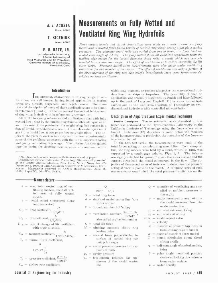
Fig. 8 The effect of a s pect ratio on the lilt and drag coefficie nts of a fully w elted ring w ing with 12 deg included cone angle. The v e locity is 18.5 Ips .
'"f 0.10
0.08 0
u
" 0.06 ~ z
"' J 0.04 ~ "' .... z w ;:; 0.02 1 <;;. ... w 0
0 u
"' "' a: o- 0.02 1 0 z
" . 0,0 4 .... ~
' - 0 .06 ·
.. 0 .0 6 1--
-0.10 l - 4
c.
- 2 .l
- I 0
-r- r - r
~ · 3
0 ~ • 2
0 2:
1 • I 5
2 ' • , .,
AN GLC or A T ... . , "< . a tO(G.I
..;
j 4
Fig. 9 The effect of a s p ect ratio on the lift and d ra g coefficients of a fully v entilated ring wing with a 12 d eg included cone angle. The v e locity Is 18.5 Ips .
wctt<>d flow i.11 Fi~. Hand in fully venti lated flow in Fig. (). The slopes of the lift emvcs a re higher for the fully wetted results t han for the ventilating, though not by much. Fig. 10 shows the effect of Froude number (or tunnel velocity) on the ring of aspect ratio two. The angle for zero lift is markedly Froude number dependent. ~ince the interior of the ventilated rin~ is filled with water and the oub>ide of the ring is expost>d to the constant pressure of the <"n.vil_, ., a major po rtion of the observed lift must be the result of the weight of t he cneloscd liquid. The force
Journal of Engineering for Industry
0.06 ---r---r T
0 .05
0.04
0.03
CORRECTED Cl
0.02
J .: 0.0.1 22 FT /SEC z w
~ ~ 0 ... w 0 u
~ -0.01
::;
: :: .. ":"' j o22 ~
-·~ _ _ ... ,--~0---'- "t 3 4
ANGLE OF ATTACK, a (OEG. )
Fig. 10 Lift coefficie nt versu s angle of attack far t he 3-in. cone at various tunne l v e locities o r Froude numbers in fully v e ntilated flow. (The lines labeled "corrected CL" a re the same a s each of the experim enta l curves except that the w e ight of the water contained by the wing has b een s ubtracted from the lift force.)
0.06 T -. 0.05
0 .04
0 .03
~ 0.02 u
.... z O.Ol w
~ ~ ~ w 0 0 u
.... ~ -0.01 ::;
-0.02
-0.03
- 0 .04
- 0.05_4 -3 ANG L E O F A T TA CK, a (OEG.)
Fig . 11 Lilt coefficie nt v ersus angle of attack far the family of cones in fully v e ntilated flaw corrected lor the w e ight of water conta ined within the volume of the ring. Tunne l velocity is 18.56 Ips .
due to this liquid was rcdn1·eJ to <·ocflieieut form for each of the test velocities and suhtmeted from the observed lift coefficients, a procednrc which tends to make the resultant curves coalC!'ct. The dn.la shown in Fig. H have been similarly corrected and presented in Fig. 11. The <"urves t hw< obtained still do not show zero lif t at r.ero angle of attack and, indeed, this zero lift angle doc:; not remain exactly <·onstant for the various rings and tunnel vel ocilic.~. This is lo ht expected since the efTe<·t of gravity on the c:witics, Fig. 2, i~ to produce a pronounced ver-
AuGusT 1 9 6 7 I 449

0.07
0.06
0.05 0
u
------------r-EST I MATE O L E DRAG
0 0.04 z .. 0
0.03
____________ l T---------4-------~~-Co
:'? z
EST I MATEO SKIN FRICTION
w u 0.02
::: w 0 0.01 u
C> .. 0: 0 0 0 z .. ... -0.01 ... ::;
-I 0 3 4 5
ANGLE OF ATTACK. a IDEG l
Fig. 12 Comparison of 3-in-chord, fully ventilated ring with results of the prenure distribution model. The solid points are the result of calculations made from measured surface pressures on the model .
tical asymmetry, while blockage of the flow by the cavity distorts the free surface of t he water in the tunnel. It is not yet possible to distinguish these two effects experimentally; nevertheless, the weight of the water contained within the ring ront ributes a major effect.
The results of the pressure distribution measurements which will be presently discussed are compared with the full ring measurements for the 3-in. (aspect ratio two) ring in Fig. 12. These results, on the whole, agree well though they are not identical. This is undoubtedly the result of the two different efTects; the direction of gravity in respect to the definition of angle of attack is difTerent in the two types of measurements. l~mm Figs. I and :l, as well as t he photographs in Figs. 2 and 4, it can be seen that nothing corresponding to the weight of the enrloscd liquid could a rise in the pressure distribution measurements. I lowever, the two lift slopes are difTerent too. This can I><' expla ined ug1\in by the difTerent orientation of the gravity force and a lso by the different conditions prevailing for tunnel interference for the reflection plane mountings. Pressure distributions a lone do not permit the determination of either frictional drag or of leading edge drag in ventilation conditions ( the latter because severe space limitations prohibit placing a sufficient number of pressure taps on the small leading edge). Calculations were made of the flat plate friction drag at the appropriate Reynolds number as well as for the leading edge pressure drag. This leading edge drag was assumed to be the same as on a circular cylinder with the same diameter as the leading edge and with a length equal to the circumference of the ring. These estimates, Fig. 12, agree quite well with the measured drag force on the 3-in. ring.
The slopes of the lift coefficient curves at zero angle of attack are summarized in Fig. 13 for all of the rings tested. It can be seen that t he fully wetted models of aspect ratios 1.5 and 2 approach fa irly closely the performance of the ventilated rings, suggesting strongly that they are, in fact, subjected to separation resulting in a fiow resembling ventilated flow except for a difTerent "cavity" pressure. The highest aspect ratio fu lly wetted conical ring approached Weissinger's theoretical values (3], and the cylindrical ring is very close to his t heory. Vistml observations on the conical ring of aspect ratio t hree with small tracer bubbles of air showed that the separation bubble at the leading edge re-
450 I Au G u s T 1 9 6 7
0
0
>-<X
" _, u
w <l. 0 ....J <J)
>-z w
~ u.. u.. w 0 u
>-u.. ::::;
2.2 ,---- r
2.0 -
1.6
0.6
0.4
0.2
FULLY W ETTED M ODELS
.0. CONI C A L 0 CYLINDRICAL
CAVITATING M ODELS
0 CONICAL
e CONICAL (PRESS OIST l
THEORY (REF. 3)
0
0
•
2 2r
1 ASPECT RATIO, c
0
3 4
Fig. 13 Lift slope values fo r the m easured ring wings in fully w etted and ventilated flow. (Data w ere obtained with both the force models and the pressu re distribut ion model.) Velo city is 18.56 fps.
Fig. 14 Selective v e ntilation over one half the p eriphery o f the ri ng for the 2·in. chord. (To prevent ventilation around the e ntire ring, s mall auxiliary "fences" are used .)
attached itself to the smfacc of the cone ahead of the trailing edge, so that values of lift slope should be near the theoretical value, as indeed they were.
The lift slope values for the fully ventilated cases appear to approach the value of 1r /4 as the aspect ratio becomes large. It is easy to show that this limit is the correct one for a ring wing of infinitesimal chord and small cone angle at zero cavitation number. It is, in fact, precisely one quarter of the lift slope for the fully wetted ring of infinite aspect ratio and, as is well known, for small an!(les of incidence to the fiow a cavitating flat plate hydrofoil at zero cavitation number has one quarter the lift of a fully wetted hydrofoil. The actual ratios of the ventilated lift slopes to those of the full~· welted theory of \\'eissinger are 0.2 ,
Transactions of the AS ME
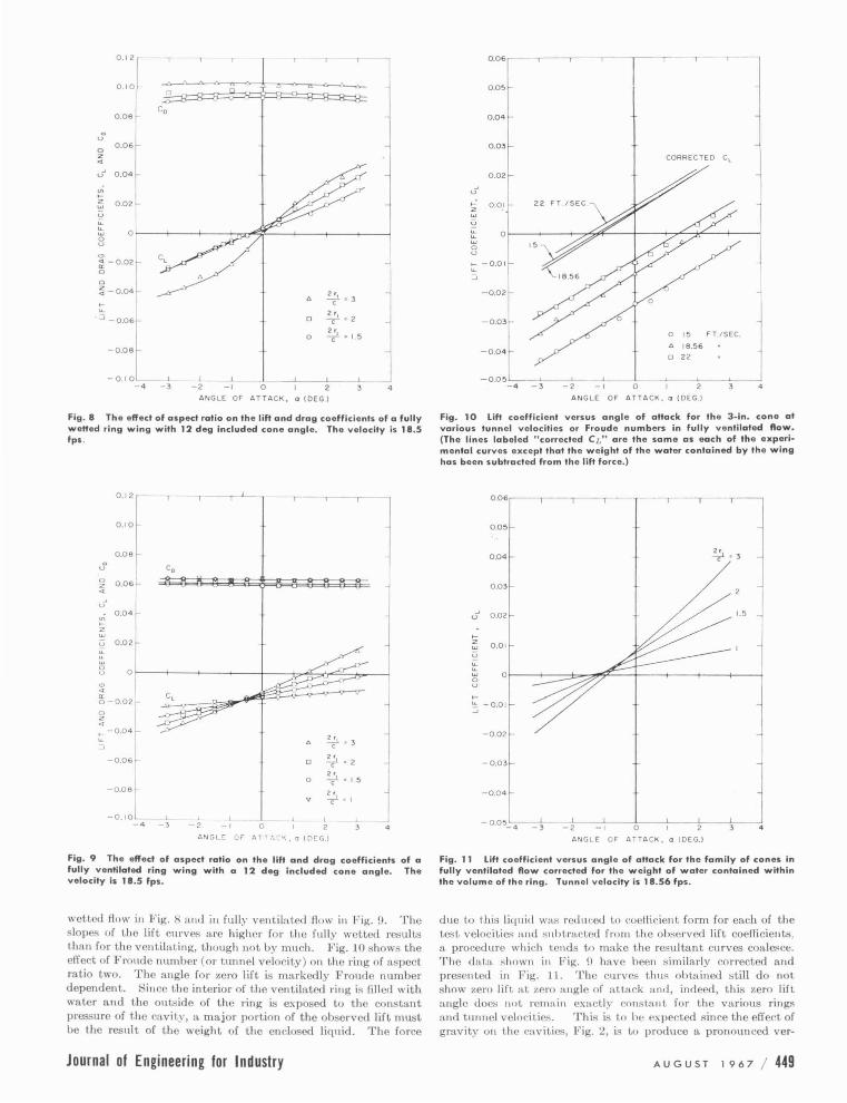
0.29, and 0.19 for the a::.peet ratios of :1, 2, and 1.5, re;pectively. All of the;;e vented flows have cavitation numbers somewhat higher t han zero, Fig. 16, and can t.herefore he expected to show a small increase in the lift slope.
Selective Ventilation . The foregoing ex[Jeriment...-; a ll deal with fL
basically axisymmetric flow. Two experiments were carried out in which only a portion of the circumference of the ring was ventilated, Fig. 14. Because t he flow pa~t t hc;;c rings is separated near the leading edge of t he eonc when fu lly wetted, the venti lation gas tended to migrate around the full circumference. This migration was prcvent('d by t he attarhmcnt of fins or fence; a ligned with the free-st ream direction and only large enough to span the cav ity at the ring. The resultant cross fo rce owing to t he partial ventilation is shown in Fig. 15 for both the 2 and :3-in. rings. It can be seen that t he magnitude of the forec developed by the partial ventilation is equivalent to an angle of attack of about 12 deg on an entire fully welled ring. The resulting vertical force is dire!'led downward for the venti lating r·oJl(lition shown in Fig. 14.
It should be remarked t lmt had t he b:t~ie ring foib not been separated ncar t he leading edge, t here would luwe been no necessity for the ventilation fences, as was found lobe t he case in reference [ll ]. The fen ces contribute a lift force opposite in direction to the developed cross force, so that the results in Fig. 15 a re at leas t conservative.
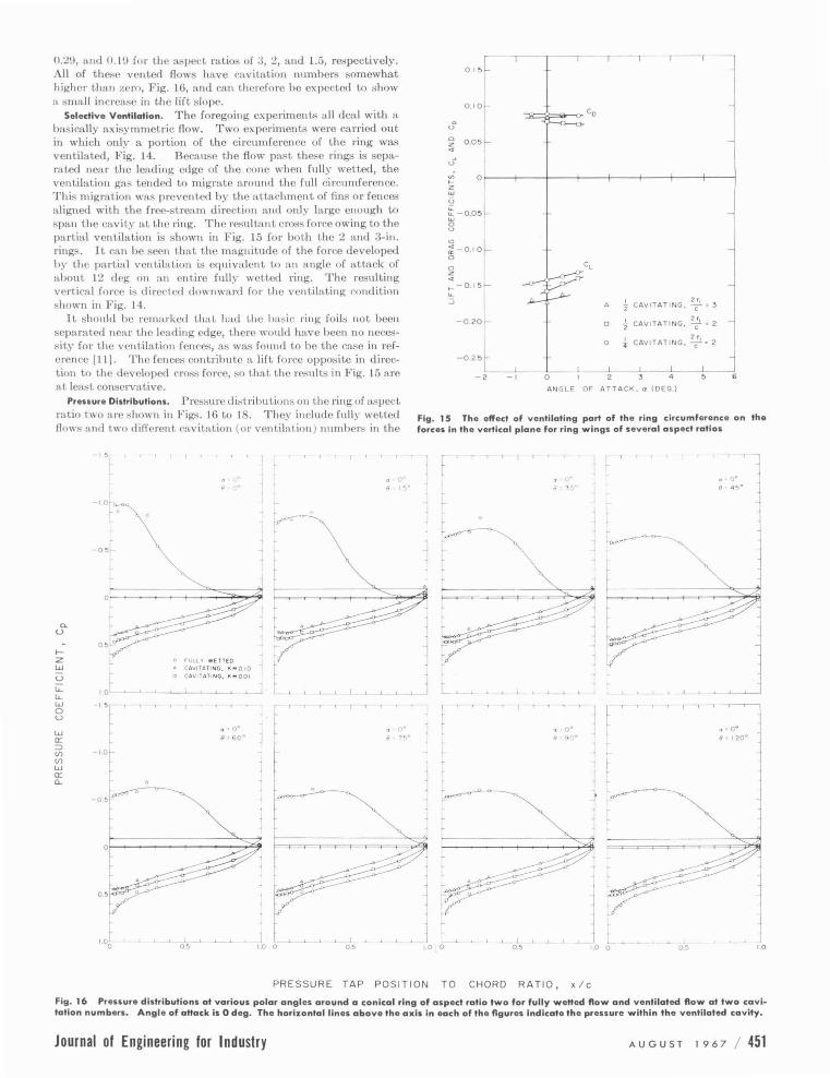
Pressure Distributions. Pressure di~tributions on t he ring of aspect ratio two nrc shown in Figs. 16 to 18. They include fully wetted flows and two difTerent r:willttion ( 01' venlilalion) number:; in the
-15
'"-\ ~ 0 0
r
_J
0
a. u
1-z w
r u "- 1 ot "-w
I 5 t ' 0 u
w a: :::J
1.0~ (f) (f) ~ w ~ a: a..
I -0 51
~ r
0
r. 0 5 l
I) 0
0 FULL'r WETTED
CAVITATING, K""010 o CAVI TATI NG, 1< • 0 0 1
I 05
J [ , L J
''
I 05
Ol 5f T T
I o 10l
0 0.05~ u
0 z .. u ~ o~---+----~--~~---+----+----4-----+--__, z w
~ - 0.05~ 0 u
"' :-0.1 0[ .,_ - 0.15
~ l 1 2 rt ..J 6 z CAVITAT I NG , C" 3
- 0.20 c ~ CAVITAT ING, ~ " 2
L 0 -} CAV ITATING,
2;
1 • 2
-0.2 5 l___ _.l___L___ _j _l____ __j
- 2 - 1 0 I 2 3 4 5
ANGL F O F ATTA CK . o ( OEG )
6
Fig. 15 The effect of ventilating part of the ring circumference on the forces in the vertical plane for ring wings of several aspect ratios
1 . ' i ' I t
1 ~ r ;~
l
! I 10 0 0.5 1.0 0
' -,
j
i l ! 10
PRESSURE TAP PO SITION TO CHORD RATIO , x/c
Fig. 16 Pressure distributions at various polar angles around a conical ring af aspect ratio two for fully weHed flow and ventilated flow at two cavitation numbers. Angle of aHack is 0 deg. The horizontal lines above the axis in each of the figures indicate the preuure within the ventilated cavity.
Journal of Engineering for Industry AuG usT 1 9 6 7 I 451

a. 0
..... z w u u._ u._ w 0 u
w a: :::> (f) (f)
w a: Q._
,.
8 ("
1.0
0 fULL1' N fTTfD • <:A.:•TA.,.·~.G. ,o; .. Q.IO 0 CAVITA'"•I,;G, ~•001
!.OL
.,- .. ~---
or--------------.-~--/-;~~~
1.0
,.
-1.0
-0.5·
\"' o----~-
I 0.5
--;. 0 ..
1.0 0 05 I.G
,, .
,• " 9 •
r
~ , .( r
t--~~ >~ -~ "" :~.~~~~::.-----~~~· ~~____,"j:
,,>(:-c~ /~
·~ / ·>
l
fi I i ~ \ \ \ \.
\ '-,
1.0
PRESSURE TAP PO SIT ION TO CHORD RATIO, x/c
Fig. 17 Pressure distributions at various polar angles around a conical ring of aspect ratio two for fully wetted ftow and ventilated ftow at two cavitation numbers. Angle of attack is 2 deg. (Experimental points at polar angles greater than 0 = 120 deg were obtained at negative angle of attack.)
452 I AuGusT 1 9 6 7 Transactions of the AS ME

- ~
-1.0
0 • •
• o•
.J 'l
0 •• " 8. 75°
1 i i
l
f-
r f-
r ~ [
T
r T
. .. . ,,
0. 4
8 9..)0
·• j J I
1
PRESSURE TAP POSITION TO CHORD RATIO, x /c
r
~ L
1.--'--'- L 0.5
r·•l 4
8 4~0
~I
1
a • 4° 8. 120° l
] ~
l ~
'- j
1 1 i
~~ 1.0
Fig. 18 Pressure distributions at various polar angles around a conical ring of aspect ratio two for fully weHed flow and ventilated flow at two cavitation numbe rs. Angle of aHack is 4 deg. (Experimental points at polar angles greater than (J = 120 deg were obtained at n egative angle of a Hack.)
Journal of Engineering for Industry AuGusT 1 9 6 7 I 453

0.7 FULLY WETTED
c 0 • • 0 u <> • • 4
.... z ~ ~ 0.5 ... ... w 0 u 0 .4 w u 0:
:;' -'
" CAVITATI N G "' 0: 0.2 0 A a • 0, K • 001 2 0 a • 0, K :. 0 . 1
0 a • 4, K • 0 .01 0.1 .. a • 4 , K • 0.1
0 30 60 90 120 150 180
POLAR ANGLE, 8 ( DEG)
Fig. 19 Radial force coefficie nts as a function of polar angle around a conical ring wing for fully wette d flow and ventilated flow for two angles of attack. The diamete r-chord ratio is 2 .0 and th e half angle of the cone is 6 d eg. The s olid s ymbols represent data obtained at negative angles of attack.
ventilated condit,ion . Pre,;~u rc distribuLions are shown for sevcnd polar a ngles 8 a round Lhc rin~, as skeL<'hed in Fi~. a. The a ppearance of Lhesc plot,s stmn~ ly suggesLs Lhc ex istence of lar~e
regions of separaLion fo r t h<' fully wct.tPd flows, c·~1wc·ially at Lhc largest an~lc of a(,(,a('k ,
Each of Lhe pressu re distri lJilLion curves was numerieally in tegraLcd to give a loc·al no rma l fo rce cocfli r icn t, as a fun ct,ion of the polar an~lc around tlw ring, a nd t,hese were t lwn plott,ed as a function of the polar a ngle, as shown iu Fi~. Hl. ThP efTecL~ of the tunnel swirl can clearly bP R<'<'n in t,his fi~ure hy cxaminat,ion of t,he curves for Lhc norma l force cocflicicnL at, zero an~le of at.tark. lf Lhcre lmd been no swirl, t,hesl' lines should be ho rizont.a l a ud independent, of polar angle. The a mount, by whic·h they dcviat,c f rom a ho rizonta l li ne drawn t hrough their maximum poin t, ( which occurs at. a pola r an~le of!)() dcg) indicat,cs t,he efT eeL of Lhe swirl at, each pola r angle. The ciTe('(, of t,hc Lunnel swirl on Lhe normal force c·oel!i('ient.;; can be climinat.ed at. a ll otl1cr :mgles of aUack by adding to them t,hi;; incremental difference at, each polar att~le . (This LaciUy assumes n. linear behav ior of force coeflicient.s wit,h local flow angle.) This was done for one of Lhe cavitating runs a nd a diagram of normal force cocffi c· icnt versuH pola r angle which has been con eeLed for swirl at. :m angle of aLLack of 4 deg and :1 cavitation numbe r of 0.01 is shown in Fig. 20. This distribuLion lli well-fiLLed by a cosine curve. Velocit.y dist.ributions were calculated from Lhe pressme disLrihu t,ions, the efTect of swirl being Lrcat.ed as in the foregoing. From Lhese, t he di ·t.ribut.ion of bound circulat.ion was calcult\Led and i;; :shown in Fig. 21. Within Lh e arcm:wy of t hese calculat,ions, this curve is ngnin adequately fi ~Lcd by a cosine curve. Such a distribuLion ~ives rise t,o an upwash consistent, with t he ring acLing as a minimum induced drag lift.ing surface [4].
With t his information, it is of int.erest Losee if an cst,imate can be made of the efTective lift slope of a two-dimens ional hydrofoil sect.ion which would be needed in a strip Lhcory calculation of the propert.ies of the lift,ing ventilated ring. In a fully wetted ring of small chord-diameter raLio we should, of course, get, 21r, t he lift, slope of :Lit isolaLcd fully welLed hydrofoil, as thi~ is Lhe basis of H.ibner's theory. Calculat,ion of the efTe('Live incidence to the local hydrofoil sect.ions requi•·es knowing t he induced radial inwash a round the hydrofoil. This depends upon Lhe circumferen t ia l dist,ribulion of bound circulat.ion and addiLional tClm;; resulting from Lhe presence of nonaxisymmctric vcnt.i latcd caviLy. These are relatively difficult, to evaluate; in what follows, we will estimate t he dis tribution of radial inwa~h from t he hound eir-
454 I A u G u s T 1 9 6 7
0.8
0.7
.; 0.6
.... z ~ 0.5 ~ ... ... w 0.4 0 u w u
0. 3 0:
:;' -'
" 0 .2
"' 0: 0 z
0.1
0
Cn • 0.300 + 0.055 cos 8
0 a • +4 DEGREES
• a • -4 DEGRE ES
30 6 0 90 120
POLAR ANGLE • 8 ( DEG I
130 180
Fig . 20 Normal forc e coefficient vers us polar angle for a ventilated ring wing of 2.0 diameter-chord ratio corrected fo r effects of tunnel s wirl. The cavitation number is 0 .01 and the angle of attack is 4 deg.
O.J
\'c •0.171 +-0.035 cosO
0.? L.,v >
L
'? > .., ..J
) u 0:
() l <
0 0 •4 DEGREES
• 0 -4 DfGREES
0 3 0 60 90 1?0 150 lBO POl 1\H ANGL. , 8 ( DEG I
Fig. 21 Distribution of circulation around the ventilated ring wing in Fig . 20
culat,ion a lone. It. can be shown Lhat, the radial inwash a ngle owing to a s inusoidal polar distribution of bound circulat,ion of ampl iLude tor i;; 57. :3 tor j 2Vc deg. The difTerence in local incidence to t he section of the ring between 0 and 90 deg pola r angle (with reference to Fig. 21) is Lhus 4 - 57.3 tor /2 V c = 2.997 deg. The co rresponding variation in norma l force coefficient i;; obtained from Fig. 20, from which we can determine that the efTecLive value of dC dda would be
dCdda = 0.055/(2.997)/(57.3) = 1.02
!lad t,he hydrofoil sections acted as two-dimensional vcnt,ilated hydrofoils in a free stream, we would have gotten the well-known result. t,hat t he lift, slope would be 1r / 2 = 1.57, which is considerably higher t han t,hat estimat.ed. Also, it is worth noting that t he overall lift slope of Lhe ring as measured from pn:>ssurc distributions, Fig. 1:3, 0.3, is only 19. percent of H.ihner's t,heory. If Lhc vent,ilalcd ring were t,o act. as in Ribner's t,heory with no account, taken of efTecL of the cav ity on local radial inwash, an efTcct.ive lift slope of the profile sections of (O.l!J )(27r ) = 1.24 would be required which is sti ll some 20 percent, higher t,han that estimated from Lhe prc~ent dat:L Although Lhese numbers arc
Transactions of the AS ME

somewhat s pcl'ulalivl', they do ~ugge:;t at Lhe very least that additional down wash effects a ris ing from the axisymmetric cavity should hr llf'I'OWJted for in such flows; it is also possible that a
eomplete lifting su rface theory accounting for t he cavity and
wetted surface in detail may be required for a full explanation. H is likely that such "sour<'e" effect:; resulting f rom the presence of a cavity will h e even more import>tnt for selective ventilation.
As mentioned in an earlier section, the axisymmetric cavity problem has ~·et to he solved for the present configuration. A
related problem is t he cavitating two-dimensional flow past a flat plate ncar the ground. The flows arc s imilar execp t that t he
one is '' plane flow and t h e other i:; axisymmetric. Values of dC ddcx have been computed for the plane flow at zero cavitation number [13]. The two-dimensional value:; give a value for t hi.-;
parameter of about 2.4-. The corre.~ponding v:tlues for zero a ngle of attack on the ring can be estimated from Fig. 19 by
dividing the average normal force coeflicient by the local angle of incidence of t he ring; namely, 6 d('g. This gives a value of
dC drlcx equ:tl to 2.8, which is in quit<' reasonable' agreement wi t h the two-dimensional value.
Acknowledgments The authors would like to :wknowk"(lgc the help of the lab
oratory ;;tafT and would especia lly like to mention t h e efforts of i\I essr:;. L. \\'hi tcanack, \\'. \\'ilson, and C. Ea.~tvedL in carrying out t he experiments. They would fmthe r like to a(·knowledge the suggc:;tions of 1\Ir. 0. Aeidman in reviewing t he manuscript. This work \\Wl supporLC'd by the Of!icc of Naval Research under Contract Nolll' 220(54) and administered under the techniC'al direction of the Bureau of Naval \\'capons, Fluid :\[eehanic.~ a nd Fligh t l)~· rutmics Bmnch, Code RHHE-4 .
References A . II. i::i"cks a nd J. A. Buruell, " DueLed Propeller" A Critical
Review of the State of the Art," Advanced Research Division of Hiller Aircraft Corporation, Heport No. ARD 232, June 26, 1959.
2 J. Levy and R. T. Knapp, "Water Tunnel Tests of the 1\IK 13-1, 1\IK 13-2 and MK 13-2A Torpedoes With Shroud lting Trails," California Institute of Technology, IIML Report N o. ND-15.1, November 24, 1943.
3 J. Weissinger, "Some Results From the Theory of the Ring \Ving in Incompressible F low," Trans. Ji'rom Advances in Aeronautical Sciences, Procecdi11(Js of Ji'irst International Congress in the Aeronautical Sciences, Madrid, Spain, September 8- 13. 1958, vol. 2 , pp. 798-831.
4 Herbert S. Ribne r, "The Ring 'Ving in Nonaxial Flow," Journal of Aeronautical Sciences, vol. 14, 1947, p. ll29.
5 A. H. Kriebel, A. H . Sacks, and J. N. Nwlsen, "Theoretical Investigation of D ynamic Stability D erivatives of Ducted Propellers," Vidya Report No. 63-95, January 9, 1963.
6 A. R. Kriebel, "Theoretical I nvestigation of Static Coefficients, Stability Derivatives, and Interference for Ducted Propellers," Vidya Report No. 112, March 3 1, 1964.
7 A. R. Kriebel, "Theoretical Stability Derivatives for a Ducted Propelle r," Vidya I nterim Report, October 18, 1963.
8 A. R. Kriebel, " In terference Bet ween a Hull and a SternMounted Dueled Propeller," \ ' idya lteport No. 161, September 30. 1964.
9 J. \\'ei~sin ger, "Hing Airfoil Theory, Problem" of I nterference a nd Boundary Layer," I nstitut fUr Angewandte Mathematik der Technischen H ochschule, Karlsruhe, Germany, J anuary, 1959.
10 J . F. Reynolds, " Lifting Surface Theory Applied to Isolated Ring Wing~ at Angle of Attack," NAVWEPS Report 8401, NOTS TP 3322, November, 196:l.
11 T. G. Lang and D. A. Day bell, "Water-Tunnel Teots of Three Vented Hydrofoils in Two-Dimensional Flow," Journal of Ship Research, vol. 5, no. 3, December, 1961.
12 ll. T . Knapp, J. Levy, .J. P. O'Neill, and F. B. B rown, "The IIydrodynami!'s Laboratory of the California I nstitute of Technology," TrHNS. ASME, vol. 70, 1948, pp. 437-457.
13 D. K . Ai, A. J. Acosta. and Z. L. Harrison, "Linearized Theory of a Two-Dimensional Planing Flat Plate in a Channel of Finite Depth-! ," California Institu te of T echnology, Hydrodynamics Laboratory lleport No. E-110.2, April. 1 fl64.
H1 printed from the At~yusl /!11!7 ./rmnud nf 1-:noinu·n'na fnr l mhn'flt'l/
Journal of Engineering for Industry Au GusT 1 9 6 7 I 455
Related Documents