NASA Technical Memorandum 106294 AIAA -93-1346 A Hot Dynamic Seal Rig for Measuring Hypersonic Engine Seal Durability and Flow Performance Jeffrey H. Miller Sverdrup Technology, Inc. Lewis Research Center Group Brook Park, Ohio Bruce M. Steinetz National Aeronautics and Space Administration Lewis Research Center Cleveland, Ohio Paul J. Sirocky Sverdrup Technology, Inc. Lewis Research Center Group Brook Park, Ohio and Lawrence A. Kren Case Western Reserve University Cleveland, Ohio Prepared for the 34th Structures, Structural Dynamics, and Materials Conference cosponsored by the AIAA, ASME, AHS, and ASC La Jolla, California, April 19-21, 1993 NASA https://ntrs.nasa.gov/search.jsp?R=19940010254 2018-06-09T18:20:46+00:00Z

Welcome message from author
This document is posted to help you gain knowledge. Please leave a comment to let me know what you think about it! Share it to your friends and learn new things together.
Transcript

NASA Technical Memorandum 106294AIAA-93-1346
A Hot Dynamic Seal Rig for MeasuringHypersonic Engine Seal Durability andFlow Performance
Jeffrey H. MillerSverdrup Technology, Inc.Lewis Research Center GroupBrook Park, Ohio
Bruce M. SteinetzNational Aeronautics and Space AdministrationLewis Research CenterCleveland, Ohio
Paul J. SirockySverdrup Technology, Inc.Lewis Research Center GroupBrook Park, Ohio
and
Lawrence A. KrenCase Western Reserve UniversityCleveland, Ohio
Prepared for the34th Structures, Structural Dynamics, and Materials Conferencecosponsored by the AIAA, ASME, AHS, and ASCLa Jolla, California, April 19-21, 1993
NASA
https://ntrs.nasa.gov/search.jsp?R=19940010254 2018-06-09T18:20:46+00:00Z
A HOT DYNAMIC SEAL RIG FOR MEASURING HYPERSONICENGINE SEAL DURABILITY AND FLOW PERFORMANCE
Jeffrey H. Miller*Sverdrup Technology, Inc.
Lewis Research Center GroupBrook Park, Ohio 44142
Bruce M. Steinetz*National Aeronautics and Space Administration
Lewis Research CenterCleveland, Ohio 44135
Paul J. Sirocky*Sverdrup Technology, Inc.
Lewis Research Center GroupBrook Park, Ohio 44142
Lawrence A. Kren**Case Western Reserve University
Cleveland, Ohio 44106
Abstract
A test fixture for measuring the dynamicperformance of candidate high-temperature engineseal concepts has been installed at NASA LewisResearch Center. The test fixture has beendesigned to evaluate seal concepts underdevelopment for advanced hypersonic engines, suchas those being considered for the NationalAerospace Plane (HASP). The fixture can measuredynamic seal leakage performance from roomtemperature up to 840'C (1550'') and au pressuredifferentials up to 690 kPa (100 psi). Performanceof the seals can be measured while sealing againstflat or distorted walls. In the fixture two seals arepreloaded against the sides of a 30 cm (1 ft) longsaber that slides transverse to the axis of the seals,simulating the scrubbing motion anticipated inthese engines. This report covers the capabilitiesof this test fixture along with preliminary datashowing the dependence of seal leakageperformance on high temperature cycling.
Introduction
Seal design requirements of advanced propulsionsystems, including hypersonic engines beingconsidered for the National Aerospace Plane andadvanced 2-dimensional, vectored-thrust turbojetfighter engines are severe [1]. The simultaneousrequirements to operate hot while sealing ramjetcombustion temperature gases of greater than2400'C (4400°F) with minimal coolant requires
Research Engineer, member AIAAResident Research Associate
Copyright C 1993 by the American Institute of Aeronauticsand Astronautics, Inc. No copyright is asserted in the
United States under Title 17, U.S. Code. The US. Govern-ment has a royalty-free license to exercise all rights underthe copyright claimed herein for Governmental purposes.
All other rights are reserved by the copyright owner.
advanced design concepts combined with hightemperature materials technology. Theperformance of these key mechanical componentsmust be evaluated prior to costly engine testing.This requires advanced test techniques which willbe described in this paper.
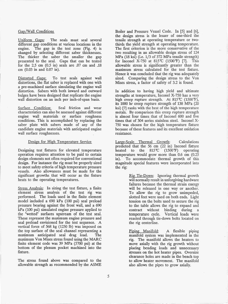
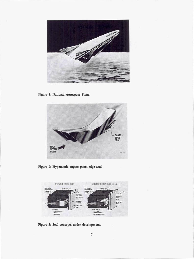
Seal concepts being developed for the NationalAerospace Plane (Fig. 1) engine are required toseal the many linear feet of gaps between themovable engine panels and the stationary enginesidewalls or sputter walls (Fig. 2). These panel-edge seals must prevent the extremely hot,pressurized flow-path gases from escaping past themovable engine panels.
Preliminary estimates of the seal design criteriaare listed in [1]. Those criteria related to thedesign of this test fixture are repeated below.1. Minimize seal leakage rates. Early
industry estimates have indicated atentative leakage rate of 6 x 10 -3 kg/m-s(4 x 10 -3 lb/ft-sec) of seal.
2. Operate at temperatures of up to 649-1090'C (1200-2000 while minimizingengine seal coolant requirements.
3. Conform to and seal against distortedadjacent sidewalls. The distortion can beas great as 4 mm over a 460 mm span(0.15 in over an 18 in span) - orapproximately 0.010 mm deflection per

millimeter of span.
4. Sustain minimal sliding damage over enginelife (estimated sliding distance is 120 m(400 ft))
roll-out under the transverse slidingmotion.
3. Measure the change in seal leakagebetween sealing against flat and distortedsidewalls.
5. Maintain material stability in the chemicallyhostile air, hydrogen, and steam engineenvironment.
Previous Work
NASA Lewis developed a high temperature statictest fixture [2] to measure seal leakage rates underengine-simulated gas temperatures (up to 8159C(1500°F)) and pressures (up to 690 kPa (100 psi)).This test fixture was used to select amongst fourcandidate seals those seals having leakage flowrates near or below the flow goal. Leakage testsrevealed that the ceramic wafer seal and braidedrope seal structures shown in Fig. 3 had relativelylow leakage rates [3] and were able to conform toand seal the distorted sidewalls.
Cooperative tests performed by Pratt & Whitney(P&W) and NASA Lewis used a simple sealscrubbing fixture to evaluate the relative durabilityperformance of competing braided rope sealarchitectures and materials [4]. In these tests, sealswere preloaded and scrubbed against an articulatingrub plate in a furnace operating at 700'C (1300'').Long term durability benefits of hybrid (ceramiccore/metal sheath) seals were demonstrated overthe all-ceramic seal designs. These scrubbing testscombined with pre- and post-leakage flowmeasurements identified seal design featuresnecessary for good durability and leakage. Fromthese tests a matrix of seal architectures wasdeveloped for subsequent testing in the currenthigh temperature dynamic seal test rig.
Seal Rig Design Criteria and Objectives
A test fixture has been installed to address thefollowing important engine seal development issues:
1. Quantify the change in seal leakage flowrates and evaluate seal durability as afunction of simulated engine cycles, attemperatures up to 815'C (1500T) andpressures up to 690 kPa (100 psi).
2. Evaluate seal leakage performance as afunction of sealed gap dimension andapplied preload. Identify limits of gapsize and applied preload to prevent seal
4. Assess dependence of seal leakage on sealmovement in the seal channel caused byseal-sidewall interactions.
5. Establish seal design guidelines identifyingseal architecture, material, and installationtechniques required for the best balance oflow leakage durable seal performance.
Test Fixture Description
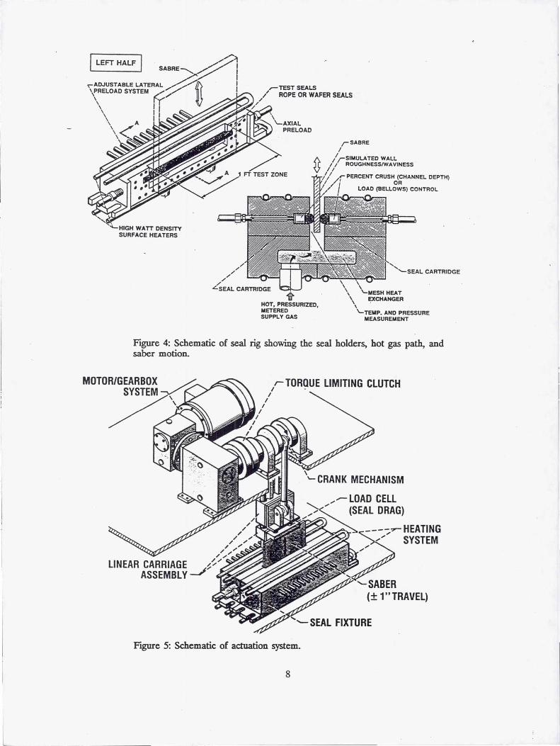
A primary consideration in designing the testfixture was to simulate the scrubbing motion theseals will experience in the actual engine. This isnecessary for examining seal wear mechanisms andconditions leading to seal roll-out. In the engine,the seals will be scrubbed transverse to their longaxes. In the test rig two seals are held in intimatecontact with an articulating saber as shown in Fig.4. The saber moves vertically through a 5 cm (2in) stroke. Sealing both sides of the saber with thecandidate test seals virtually eliminates the need forother supporting seals that must operate at the fulloperating temperature.
End-Leakage Control
Unlike circular seals, linear seals unavoidably havetwo ends. Treatment of the ends is critical toobtaining accurate measurement of the seal'sleakage performance. Two steps were taken tovirtually eliminate end leakage in the test rig. Toseal the ends of the articulating saber, rub blocksmade of Inconel X-750 material are employed.These rub blocks are machined flat and paralleland rub against both ends of the articulating saber.They are preloaded against the ends of the saberthrough pneumatically-actuated, hermetically-sealedbellows axial preloaders (Fig. 4), developed in [2].The rub blocks were machined to nominaldimensions and hand-lapped in place for a precisefit with their mating rub-block cavities. Thisapproach minimizes leakage past the rub-blocks.
Another feature controlling seal end-leakage,demonstrated in previous rig designs [2], is thetechnique of "building-in" the ends of the seal intothe test rig. The seal test zone and saber arenominally 30 cm (12 in) long. The seals extend afew centimeters beyond the test zone on both ends.
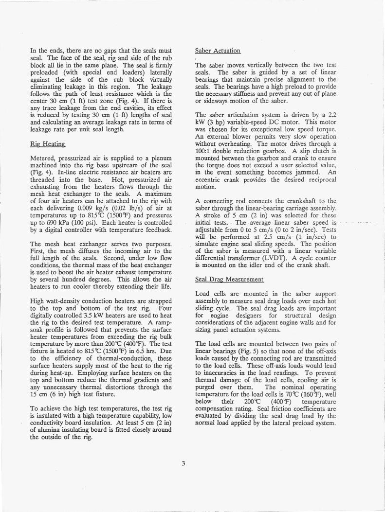
In the ends, there are no gaps that the seals mustseal. The face of the seal, rig and side of the rubblock all lie in the same plane. The seal is fu-mlypreloaded (with special end loaders) laterallyagainst the side of the rub block virtuallyeliminating leakage in this region. The leakagefollows the path of least resistance which is thecenter 30 cm (1 ft) test zone (Fig. 4). If there isany trace leakage from the end cavities, its effectis reduced by testing 30 cm (1 ft) lengths of sealand calculating an average leakage rate in terms ofleakage rate per unit seal length.
Rid Heating
Metered, pressurized air is supplied to a plenummachined into the rig base upstream of the seal(Fig. 4). In-line electric resistance air heaters arethreaded into the base. Hot, pressurized airexhausting from the heaters flows through themesh heat exchanger to the seals. A maximumof four air heaters can be attached to the rig witheach delivering 0.009 kg/s (0.02 lb/s) of air attemperatures up to 815`C (1500'') and pressuresup to 690 kPa (100 psi). Each heater is controlledby a digital controller with temperature feedback.
The mesh heat exchanger serves two purposes.First, the mesh diffuses the incoming air to thefull length of the seals. Second, under low flowconditions, the thermal mass of the heat exchangeris used to boost the air heater exhaust temperatureby several hundred degrees. This allows the airheaters to run cooler thereby extending their life.
High watt-density conduction heaters are strappedto the top and bottom of the test rig. Fourdigitally controlled 3.5 kW heaters are used to heatthe rig to the desired test temperature. A ramp-soak profile is followed that prevents the surfaceheater temperatures from exceeding the rig bulktemperature by more than 200 9C (400''). The testfixture is heated to 815'C (1500°F) in 6.5 hrs. Dueto the efficiency of thermal-conduction, thesesurface heaters supply most of the heat to the rigduring heat-up. Employing surface heaters on thetop and bottom reduce the thermal gradients andany unnecessary thermal distortions through the15 cm (6 in) high test fixture.
To achieve the high test temperatures, the test rigis insulated with a high temperature capability, lowconductivity board insulation. At least 5 cm (2 in)of alumina insulating board is fitted closely aroundthe outside of the rig.
Saber Actuation
The saber moves vertically between the two testseals. The saber is guided by a set of linearbearings that maintain precise alignment to theseals. The bearings have a high preload to providethe necessary stiffness and prevent any out of planeor sideways motion of the saber.
The saber articulation system is driven by a 2.2kW (3 hp) variable-speed DC motor. This motorwas chosen for its exceptional low speed torque.An external blower permits very slow operationwithout overheating. The motor drives through a100:1 double reduction gearbox. A slip clutch ismounted between the gearbox and crank to ensurethe torque does not exceed a user selected value,in the event something becomes jammed. Aneccentric crank provides the desired reciprocalmotion.
A connecting rod connects the crankshaft to thesaber through the linear-bearing carriage assembly.A stroke of 5 cm (2 in) was selected for theseinitial tests. The average linear saber speed isadjustable from 0 to 5 cm/s (0 to 2 in/sec). Testswill be performed at 2.5 cm/s (1 in/sec) tosimulate engine seal sliding speeds. The positionof the saber is measured with a linear variabledifferential transformer (LVDT). A cycle counteris mounted on the idler end of the crank shaft.
Seal Drag Measurement
Load cells are mounted in the saber supportassembly to measure seal drag loads over each hotsliding cycle. The seal drag loads are importantfor engine designers for structural designconsiderations of the adjacent engine walls and forsizing panel actuation systems.
The load cells are mounted between two pairs oflinear bearings (Fig. 5) so that none of the off-axisloads caused by the connecting rod are transmittedto the load cells. These off-axis loads would leadto inaccuracies in the load readings. To preventthermal damage of the load cells, cooling air ispurged over them. The nominal operatingtemperature for the load cells is 70'C (160''), wellbelow their 200'C (400'F) temperaturecompensation rating. Seal friction coefficients areevaluated by dividing the seal drag load by thenormal load applied by the lateral preload system.

Test Condition Measurement
Leakage Measurement: Leakage rates aremeasured upstream of the in-line heaters. Leakageis measured in this manner for several reasons.Measuring the mass flow prior to heating to 8159C(15007) precludes the need to cool the gas beforemeasuring it with room temperature flowmeters.Eliminating the need to capture the leaked gas andthen cool it saves considerable expense andcomplexity. Measuring the leakage flow upstreamof the seal also gives a conservative estimate of theactual seal leakage rate. The leakage rate that ismeasured includes both the seal leakage and anyminor parasitic leakage mentioned earlier. Threeflow meters (Teledyne Hastings HFM-201) arearranged in parallel in a flow bench and areswitch-selectable to measure air flows in thefollowing ranges: 0 - 0.009 kg/s, 0 - 0.018 kg/s, 0- 0.036 kg/s ( 0 - 0.02 lb/sec, 0.04 lb/sec, 0.08lb/sec).
Pressure Measurement: The pressure differentialapplied across the seal is evaluated using staticpressure taps immediately upstream of the seal.Gage pressure measurements are used since theseal vents to atmospheric conditions and the exitingflow velocities are low. The pressures aremeasured using solid-state capacitance typetransducers. Pressure is supplied to thetransducers using suitably long (over 15 cm) tubing,to prevent high temperatures from reaching thetransducer. Measurements are taken at multipleaxial stations so that an accurate average pressuredifferential is obtained.
Pressures are also measured in the seal cavitybehind the seal to determine fluid forces exertedby the chamber pressure. Pressure supplied tothe lateral preload bellows is also measured, fromwhich the seal contact stress is calculated.
Temperature Measurement: The temperature ofthe gas impinging on the seal is measured usingfast-acting thermocouples just upstream of the seal.The thermocouple beads are inserted in the gasstream to measure true gas temperature. Foraveraging purposes, multiple thermocouples areused along the length of each of the 30 cm (1 ft)seals. Thermocouples are placed at the exhaust ofthe air heaters and on the surface heaters tomonitor temperature and provide feedback signalsfor the respective controllers.
In all cases, type K (Chromel-Alumel; 1090'C)
thermocouples are used. Wherever thermocouplesor static pressure taps are inserted into thepressurized rig, special high temperature fittings areused to prevent parasitic leakage. These fittingsare made by Conax Co. and use a proprietaryfitting design with magnesium-oxide (lava) typeglands capable of 982 9C (18W F) operation.
All sensors are continuously monitored with aPC-based data acquisition system. The hostplatform is a 486 PC with a LabMaster analog-to-digital converter board. Lab Tech Notebook XEsoftware is used to record and display the data.
Seal Preload and Measurement: An importantparameter requiring investigation is the seal preloadrequired to adequately seal the pressurized gas.Both lateral preload (i.e., transverse to the sealaxis) and axial preload (i.e. rub-block) aremeasured in the rig. Lateral preload is appliedusing a series of welded-leaf, flexible Inconel 718metal bellows (Fig. 4). These 13 cm (0S in)diameter bellows are mounted on 2.5 cm (1 in)centers and are pressurized from a commonmanifold. In-line with each of the bellows pressuresupply tubes is a hand valve that can be used toselect the number of active bellows.
A thin (.15 cm (0.06 in)) strip of Inconel is placedbetween the nose of the sealed bellows and theback of the candidate seal. This strip distributesthe preload to portions of the seal between twoadjacent bellows. An average seal contact pressureis determined by pro-rating bellows pressure (asmeasured in the manifold supply) by the ratio ofthe bellows area to the backside seal area. If allof the bellows are active the average contactpressure is the bellows supply pressure divided by6.5.
Fixed Preload: In certain areas of the engine,replacing the "active" preload system with a fixedpreload is desirable if seal performance does notsuffer. To evaluate the effect of a fixed preloadon leakage and durability, the bellows preloadsystem described previously is replaced with a crushbar that is placed behind the seal. These crushbars are installed with shims to effect the properinitial percent crush on the seal. Early durabilitystudies [4] showed the drop off in seal preload withcycling in a fixed preload set-up, but could notmeasure leakage. The current fixture will enableleakage measurement over the course of sealcycling to determine acceptability of seal flowperformance.
4
Gap/Wall Conditions
Uniform Gaps: The seals must seal severaldifferent gap conditions at various locations in theengine. The gap in the test zone (Fig. 4) ischanged by selecting different saber thicknesses.The thicker the saber the smaller the gappresented to the seal. Gaps that can be testedfor the 2.5 cm (0.5 in) seals are .07 cm and .18cm (0.03 in and 0.07 in).
Distorted Gaps: To test seals against walldistortions, the flat saber is replaced with one witha pre-machined surface simulating the engine walldistortion. Sabers with both inward and outwardbulges have been designed that replicate the enginewall distortion on an inch per inch-of-span basis.
Surface Condition: Seal friction and wearcharacteristics can also be assessed against differentengine wall materials or surface roughnessconditions. This is accomplished by replacing thesaber plate with sabers made of any of thecandidate engine materials with anticipated enginewall surface roughnesses.
Design for High Temperature Service
Designing test fixtures for elevated temperatureoperation requires attention to be paid to certaindesign elements not often required for conventionaldesign. For instance the rig must be properly sizedto meet safety criteria of high temperature pressurevessels. Also allowances must be made for thesignificant growths that will occur as the fixtureheats to the operating temperatures.
Stress Anal: In sizing the test fixture, a finiteelement stress analysis of the test rig wasperformed. The loads used in the finite elementmodel included a 690 kPa (100 psi) seal preloadpressure bearing against the front wall, and a 690kPa (100 psi) simulated engine pressure applied tothe "wetted" surfaces upstream of the test seal.These represent the maximum engine pressure andseal preload envisioned for the test sequence. Avertical force of 568 kg (1250 lb) was imposed onthe top surface of the seal channel representing amaximum anticipated seal drag load. Themaximum Von Mises stress found using the MARCfinite element code was 39 MPa (5700 psi) at thebottom of the plenum pocket machined into thefixture.
The stress found above was compared to theallowable strength as recommended by the ASME
Boiler and Pressure Vessel Code. In [5] and [6],the design stress is the lesser of one-third thetensile strength at operating temperature or two-thirds the yield strength at operating temperature.The first criterion is the more conservative of thetwo resulting in an allowable design stress of 124MPa (18 ksi) (i.e. 1/3 of 372 MPa tensile strength)for Inconel X-750 at 815 cC (1500 cF) [7]. Thisallowable stress is significantly greater than themaximum stress calculated for the test fixture.Hence it was concluded that the rig was adequatelysized. Comparing the design stress to the VonMises stress, a factor of safety of 3.2 is found.
In addition to having high yield and ultimatestrengths at temperature, Inconel X-750 has a veryhigh creep rupture strength. At 815 90 (1500°F),its 1000 hr creep rupture strength of 138 MPa (20ksi) [7] ranks with the best of the high temperaturemetals. By comparison this creep rupture strengthis almost four times that of Inconel 600 and fivetimes that of 304 series stainless steel. Inconel X-750 was chosen for the high temperature fixturebecause of these features and its excellent oxidationresistance.
Large-Scale Thermal Growth: Calculationspredicted that the 56 cm (22 in) Inconel fixtureheated to the 815 90 (1500'') operatingtemperature would grow more than 0.6 cm (0.25in). To accommodate thermal growth of thismagnitude special features were incorporated intothe rig:
Rig Tie-Down: Ignoring thermal growthwill normally result in unforgiving hardwarefailures because the thermal strain energywill be released in one way or another.To allow the rig to grow unimpeded,slotted feet were used on both ends. Lighttension on the bolts used to secure the rigto the table allows the rig to expand andcontract without binding during atemperature cycle. Vertical loads werereacted through tie-down bolts located onthe rig centerline.
Piping Manifold: A flexible pipingmanifold system was implemented in therig. The manifold allows the heaters tomove axially with the rig growth withoutplacing bending loads and unnecessarystresses on the hot heater pipes. Oversizeclearance holes are made in the bench topto allow heater movement. The manifoldalso allows the pipes to grow axially.

Axial Preload System: The axial preloadsystem actuates the end rub blocks. Therub blocks seal the leakage path at theends of the saber. As shown in Fig. 6, theload cells and pneumatic actuators arebracketed to the base of the rig. Thisguarantees that the load cell reading willnot be affected by forces caused by thethermal expansion of the rig.
Test Fixture Demonstration
The design features incorporated into the testfixture allows a broad range of candidate engineseal concepts to be tested. The test rig is easilyconfigured to test the ceramic wafer seal and thebraided ceramic rope seal.
Seal Specimen: For purposes of demonstratingthe high temperature capability of the test rig, theceramic rope seal depicted in Fig. 3 was installedand tested.
Test Results: Leakage rates for the ceramic ropeseal sealing 843C (1550'F) air are shown versuspressure drop in Fig. 7 after 1200 cycles. In thisfigure, the hot leakage rates are normalized by theleakage rate before cycling. These results show areduction in leakage with cycling. Though leakagerates were low, the seal was badly damaged duringthe test indicating that alternative designs such asthe hybrid seals are required to withstand thepunishing engine sliding conditions.
Summary
A hot dynamic test fixture for evaluating theperformance of advanced hypersonic engine sealshas been installed and successfully checked-out atNASA Lewis Research Center. The test fixturewill be used to assess the durability and flowchange of candidate seals as a function ofsimulated engine cycles. The fixture can subjectseals to simulated temperatures up to 815cC(1550 cF) and pressures up to 690 kPa (100 psi).Furthermore, seal performance in sealing eitherstraight or distorted sidewalls can be measured.The sensitivity of leakage performance to eitheractive or fixed preload can also be evaluated.
Acknowledgements
The authors acknowledge Mr. Mike Tong for therig stress analysis, Mr. Frank Jasko for detaileddesign of the components, and Mr. RichardTashjian for the test fixture installation.
References
1. Steinetz, B.M.: "Evaluation of an InnovativeHigh Temperature Ceramic Wafer Seal forHypersonic Engine Applications," NASATM-105556, 1992.
2. Steinetz, B.M.: "A Test Fixture forMeasuring High-Temperature HypersonicEngine Seal Performance," NASA TM-103658, 1990.
3. Steinetz, B.M., et al: "Engine Panel Sealsfor Hypersonic Engine Applications: HighTemperature Assessments and FlowModelling," NASA TM-105260, 1992.
4. Steinetz, B.M., et al: "High TemperatureDynamic Engine Seal TechnologyDevelopment," NASA TM-105641, 1992.
5. Boiler and Pressure Vessel Code, SectionVIII, Division 1. American Society ofMechanical Engineers (1980).
6. Boiler and Pressure Vessel Code, SectionVIII, Division 2. American Society ofMechanical Engineers (1980).
7. Kattus, J.R., "Inconel X-750," AerospaceStructural Metals Handbook, Metals andCeramics Information Center, BattelleLabs, Columbus, OH, Vol. 4, Article 4105(1990).
Note: Mention of manufacturers is made onlyfor reference purposes and does not constitute aproduct endorsement by NASA or the U.S.government.
6
^^
Figure 1: National Aerospace Plane.
r
1
PANEL-EDGESEAL
HIGHSPEEDFLOW
Figure 2: Hypersonic engine panel -edge seal.
Ceramic wafer Seat
rovne^.EFro- Cw. F;AwWICON'4
DMCJC '1AMC: .FCY
CCOV4FOR wGf— Fws
1 i ErN
..—w...0YEn
rr^^.'rFA
( M^
COOGFmE.Sti. JR¢[^^Kph
^ tiOM
Sraided ceramic rope seal
rov.0 "OTC FLAWMdE.`OIlrA^FMgBE ^^RArfSAP^'^ON
L ^^LA;
-OR:10FU:coolEcQiSJRLTDr['^: sLUOwS
Figure 3: Seal concepts under development.
7
MOTORIGEARBOXSYSTEM /
r--TORQUE LIMITING CLUTCH
LEFT HALFSABRE
i-TEST SEALSi ROPE OR WAFER SEALS
-SABRE
SIMULATED WALLROUGHNESSIWAVINESS
PERCENT CRUSH (CHANNEL DEPTH)OR
LOAD (BELLOWS) CONTROL
HIGH WATT DENSITYSURFACE HEATERS
SEAL CARTRIDGE
--'- -........^^` A •^ -MESH HEAT
tl ^^ EXCHANGERHOT, PRESSURIZED,METERED '-TEMP. AND PRESSURE
SUPPLY GAS MEASUREMENT
Figure 4: Schematic of seal rig showing the seal holders, hot gas path, andsaber motion.
`CRANK MECHANISM
LOAD CELL
^^(SEAL DRAG)
--- -HEATINGSYSTEM
LINEAR CARRIAGE
ASSEMBLY --'j-SABER(± 1"TRAVEL)
\ SEAL FIXTURE
Figure 5: Schematic of actuation system.
8

Figure 6: Photograph of high temperature dynamic seal rig.
(n 0.5a^U
00.4
.E0.3
U)a^
0.2
C)
0 0.1N
•E 0.0010 20 30 4-0 50 60 70 80
Engine Pressure (psig)1 psi = 6.895 kPo
Figure 7: Preliminary data showing high temperature (815r (1550°F)) sealleakage after simulated engine duty cycle showing decrease in seal leakagewith cycling.
9

Form ApprovedREPORT DOCUMENTATION PAGE OMB No. 0704-0188
Public reporting burden for this collection of information is estimated to average 1 hour per response, including the time for reviewing instructions, searching existing data sources,gathering and maintaining the data needed, and completing and reviewing the collection of information. Send comments regarding this burden estimate or any other aspect of thiscollection of information, including suggestions for reducing this burden, to Washington Headquarters Services. Directorate for Information Operations and Reports, 1215 JeffersonDavis Highway, Suite 1204, Arlington, VA 22202-4302, and to the Office of Management and Budget, Paperwork Reduction Project (0704-0188), Washington, DC 20503.
1. AGENCY USE ONLY (Leave blank) 2. REPORT DATE 3. REPORT TYPE AND DATES COVERED
April 1993 Technical Memorandum4. TITLE AND SUBTITLE S. FUNDING NUMBERS
A Hot Dynamic Seal Rig for Measuring Hypersonic Engine SealDurability and Flow Performance
WU— 763-22-4 16. AUTHOR(S)
Jeffrey H. Miller, Bruce M. Steinetz, Paul J. Sirocky, and Lawrence A. Kren
7. PERFORMING ORGANIZATION NAME(S) AND ADDRESS(ES) 8. PERFORMING ORGANIZATIONREPORT NUMBER
National Aeronautics and Space AdministrationLewis Research Center E-8031Cleveland, Ohio 44135-3191
9. SPONSORING/MONITORING AGENCY NAME(S) AND ADDRESS(ES) 10. SPONSORING/MONITORINGAGENCY REPORT NUMBER
National Aeronautics and Space AdministrationWashington, D.C. 20546-0001 NASA TM— 106294
11. SUPPLEMENTARY NOTESPrepared for the 34th Structures, Structural Dynamics, and Materials Conference cosponsored by the AIAA, ASME, AHS, and ASC, La Jolla,California, April 19-21, 1993. Jeffery H. Miller and Paul J. Sirocky, Sverdrup Technology, Inc., Lewis Research Center Group, 2001 AerospaceParkway, Brook Park, Ohio 44142; Bruce M. Steinetz, NASA Lewis Research Center and Lawrence A. Kren, Case Western Reserve University,Cleveland Ohio 44106. Responsible person, Bruce M. Steinetz 216 433-6012.
12a. DISTRIBUTION/AVAILABILITY STATEMENT 12b. DISTRIBUTION CODE
Unclassified - UnlimitedSubject Category 37
13. ABSTRACT (Maximum 200 words)
A test fixture for measuring the dynamic performance of candidate high-temperature engine seal concepts has beeninstalled at NASA Lewis Research Center. The test fixture has been designed to evaluate seal concepts under develop-ment for advanced hypersonic engines, such as those being considered for the National Aerospace Plane (HASP). Thefixture can measure dynamic seal leakage performance from room temperature up to 840 °C (1550 °F) and airpressure differentials up to 690 kPa (100 psi). Performance of the seals can be measured while sealing against flat ordistorted walls. In the fixture two seals are preloaded against the sides of a 30 cm (1 ft) long saber that slides trans-verse to the axis of the seals, simulating the scrubbing motion anticipated in these engines. This report covers thecapabilities of this test fixture along with preliminary data showing the dependence of seal leakage performance onhigh temperature cycling.
14. SUBJECT TERMS 15. NUMBETC^F PAGES
Seal; Experiment; Design; Wear; High-temperature 16. PRICE CODE
A0317. SECURITY CLASSIFICATION 18. SECURITY CLASSIFICATION 19. SECURITY CLASSIFICATION 20. LIMITATION OF ABSTRACT
OF REPORT OF THIS PAGE OF ABSTRACT
Unclassified Unclassified Unclassified
NSN 7540-01-280-5500 Standard Form 298 (Rev. 2-89)Prescribed by ANSI Std. Z39-18298-102
Related Documents