1 Abstract— Today, safety and security is just a click of the appropriate technology away, and with such advancements happening, the security of one’s home must also not be left behind. This project is an example of the use of digital systems design to accomplish that goal, where the security and comfort of a home is the issue at hand. This device has been modeled such that it takes care of home intrusion detection and avoidance, while it also controls other home environment factors such as temperature and smoke detection. A sequential pattern of controlling the front door, rear door, windows, fire alarm and temperature is followed in a priority order. The solution uses the hardware design system concepts of a state machine to design a Mealy system that is simulated in VHDL using Cadence. The expected output is achieved in the waveforms of the system, which is in agreement with the theoretical results expected and has realized the objective of controlling the home system. Index Terms— Mealy system, VHDL, Digital Design, Cadence, security, sensors, state diagram, simulation, states, waveforms I. INTRODUCTION Background This applied project is a ‘Home Automation System’ using the design concepts for a hardware system. Due to the number of thefts and increased risk of robbery, it is necessary to have a security system for home. ‘Security’ is the prime word in any business and since that being so important, is a very helpful and good topic for the benefit of mankind to develop a secure and safe system, which will prevent any break-ins to the home and also provide the comfort of controlling the temperature. Such systems are already available in the market, suiting varying needs. But, if the consumer wants just one system, which can control the entire house, then there is a problem as there is no such equipment in the market yet. Home automation systems can control many things in a home, which are precious and valuable to a person. For example, the doors, windows, fire alarm and temperature can be controlled by just one click, just to ensure that all these are safe, when the occupants of the house are either at home or out or to just sit in one place and control these devices instead of having to get to that place to perform a certain action. The controller does its work of checking each of the devices periodically and in a certain order. The system can be controlled by a remote or any device that can be connected to all the devices that need to be secure. Their Manuscript received November 21, 2003. The title of the applied project is ‘Home Automation System using Hardware Design Concepts’. Sirisha Vasala. is with the Electronics and Computer Engineering Technology Department at Arizona State University East, Mesa, AZ 85287 USA (corresponding author to provide phone: 480-282-0465; e-mail: [email protected]). communication is through sensors which are attached on all the devices. This is a relatively new concept and has not hit the market so extensively yet, but once it does then it will definitely be very much in demand and so there will be a constant need for something so secure and safe. Problem This project is to design a controller, which provides an automated home security system at an affordable price. The parameter sensors connected to the controller will provide the required signals that will activate controller processes to and take the specified action. Scope A system is designed to control the doors, windows, fire alarm and the temperature. It is not intended or programmed to control anything else. Due to the short scope and to be realistically bound, certain assumptions are made in this applied project and certain concepts are overlooked at. This project is being implemented to control only these devices but can be expanded later on to control more devices or processes and also can be web enabled. Specifications There are sensors for all four of the processes being automated. The sensors used are magnetic sensor (for doors and windows), smoke detector (for fire) and a thermostat (for temperature). Every device will have a sensor that indicates how secure a system is by sending out a signal in case there is a change in the state. HI (1) indicates the system will need to take action and LO (0) indicates the device is safe so, the next device can be checked. The doors and windows operate on a magnetic sensor, if the signal on either is high (1) then the operation is to close the door or buzz for the window to be closed. If the signal is a low (0), then the controller goes forward to check for the signal on the next device. There are separate magnetic sensors on both the front door and the rear door. The sensor on the fire alarm is a smoke detector, if it detects smoke then the signal goes to a high (1) and it triggers off the buzzer, else it goes to the next step. The temperature controller has a thermostat on it that responds to with the required action depending on the temperature and then goes back to the beginning. The no-action temperature range is from 50 o F – 70 o F. If the temperature goes below the range then the heater turns itself on, if it goes above the range then the air conditioner turns itself on. E. Assumptions Due to the limited time constraints and also due to hardware inaccessibility and cost restrictions, it was assumed that readily available sensors are used on all the devices and no special program or design is followed for the same. Also, this project would be implemented in phases so that it would be easier to track and make changes. The scope of this project would remain at just controlling A Home Automation System Using Hardware Design Concepts Sirisha Vasala

Welcome message from author
This document is posted to help you gain knowledge. Please leave a comment to let me know what you think about it! Share it to your friends and learn new things together.
Transcript
1
Abstract— Today, safety and security is just a click of the appropriate technology away, and with such advancements happening, the security of one’s home must also not be left behind. This project is an example of the use of digital systems design to accomplish that goal, where the security and comfort of a home is the issue at hand. This device has been modeled such that it takes care of home intrusion detection and avoidance, while it also controls other home environment factors such as temperature and smoke detection. A sequential pattern of controlling the front door, rear door, windows, fire alarm and temperature is followed in a priority order. The solution uses the hardware design system concepts of a state machine to design a Mealy system that is simulated in VHDL using Cadence. The expected output is achieved in the waveforms of the system, which is in agreement with the theoretical results expected and has realized the objective of controlling the home system.
Index Terms— Mealy system, VHDL, Digital Design, Cadence, security, sensors, state diagram, simulation, states, waveforms
I. INTRODUCTION
Background This applied project is a ‘Home Automation System’ using the design concepts for a hardware system. Due to the number of thefts and increased risk of robbery, it is necessary to have a security system for home. ‘Security’ is the prime word in any business and since that being so important, is a very helpful and good topic for the benefit of mankind to develop a secure and safe system, which will prevent any break-ins to the home and also provide the comfort of controlling the temperature. Such systems are already available in the market, suiting varying needs. But, if the consumer wants just one system, which can control the entire house, then there is a problem as there is no such equipment in the market yet. Home automation systems can control many things in a home, which are precious and valuable to a person. For example, the doors, windows, fire alarm and temperature can be controlled by just one click, just to ensure that all these are safe, when the occupants of the house are either at home or out or to just sit in one place and control these devices instead of having to get to that place to perform a certain action. The controller does its work of checking each of the devices periodically and in a certain order. The system can be controlled by a remote or any device that can be connected to all the devices that need to be secure. Their
Manuscript received November 21, 2003. The title of the applied project is ‘Home Automation System using Hardware Design Concepts’. Sirisha Vasala. is with the Electronics and Computer Engineering Technology Department at Arizona State University East, Mesa, AZ 85287 USA (corresponding author to provide phone: 480-282-0465; e-mail: [email protected]).
communication is through sensors which are attached on all the devices. This is a relatively new concept and has not hit the market so extensively yet, but once it does then it will definitely be very much in demand and so there will be a constant need for something so secure and safe.
Problem This project is to design a controller, which provides an automated home security system at an affordable price. The parameter sensors connected to the controller will provide the required signals that will activate controller processes to and take the specified action.
Scope A system is designed to control the doors, windows, fire alarm and the temperature. It is not intended or programmed to control anything else. Due to the short scope and to be realistically bound, certain assumptions are made in this applied project and certain concepts are overlooked at. This project is being implemented to control only these devices but can be expanded later on to control more devices or processes and also can be web enabled.
Specifications There are sensors for all four of the processes being automated. The sensors used are magnetic sensor (for doors and windows), smoke detector (for fire) and a thermostat (for temperature). Every device will have a sensor that indicates how secure a system is by sending out a signal in case there is a change in the state. HI (1) indicates the system will need to take action and LO (0) indicates the device is safe so, the next device can be checked. The doors and windows operate on a magnetic sensor, if the signal on either is high (1) then the operation is to close the door or buzz for the window to be closed. If the signal is a low (0), then the controller goes forward to check for the signal on the next device. There are separate magnetic sensors on both the front door and the rear door. The sensor on the fire alarm is a smoke detector, if it detects smoke then the signal goes to a high (1) and it triggers off the buzzer, else it goes to the next step. The temperature controller has a thermostat on it that responds to with the required action depending on the temperature and then goes back to the beginning. The no-action temperature range is from 50o F – 70o F. If the temperature goes below the range then the heater turns itself on, if it goes above the range then the air conditioner turns itself on.
E. Assumptions Due to the limited time constraints and also due to hardware inaccessibility and cost restrictions, it was assumed that readily available sensors are used on all the devices and no special program or design is followed for the same. Also, this project would be implemented in phases so that it would be easier to track and make changes. The scope of this project would remain at just controlling
A Home Automation System Using Hardware Design Concepts
Sirisha Vasala

2
the system internally; the hardware aspects of this would be dealt with in the next phase. According to the devices, the assumptions are categorized as below. The following are the assumptions for operating the front and the rear doors: Sensor on the door, which is a magnetic sensor, is always LO (0) indicating the door is always closed. There are 2 doors and each has a different magnetic sensor attached to it. When the sensor detects a HI (1), the magnetic sensor automatically closes the door. This is achieved since a magnetic sensor is used. The following are the assumptions for operating the windows: The system covers all the windows. A +5V power is supplied to the system. Only the status of the window is checked for and if the window is open (1) then the system buzzes until it is manually turned off. The default state of the window is LO (0). The sensor on the window, which is same as the sensor on the door, a magnetic sensor, is always on low (0) indicating the window is closed always. The assumptions for operating the fire alarm are: A smoke detector is present to detect the smoke. There is a constant source of electricity of +5V to the sensor and devices. If there is any smoke detects a HI (1) on the sensor, the fire alarm starts buzzing and continues to do so until it has been turned of manually, it sends out the signal. The state of the fire alarm then returns to LO (0), and this is the default state. The following are the assumptions for controlling the temperature: The range from 50o F to 70o F is considered to be the comfortable range in the home. The sensor used here is the thermostat, which measures the changes in room temperature and turns on the heater or the cooler based on the temperature inside the room. Assuming the sensor records temperature below 50o F, then the heater is turned and the air conditioner turns itself on if the temperature is above 70o F. For both the conditions the sensor goes HI (1), else it remains on the LO (1) state. The power is from a +5V power source.
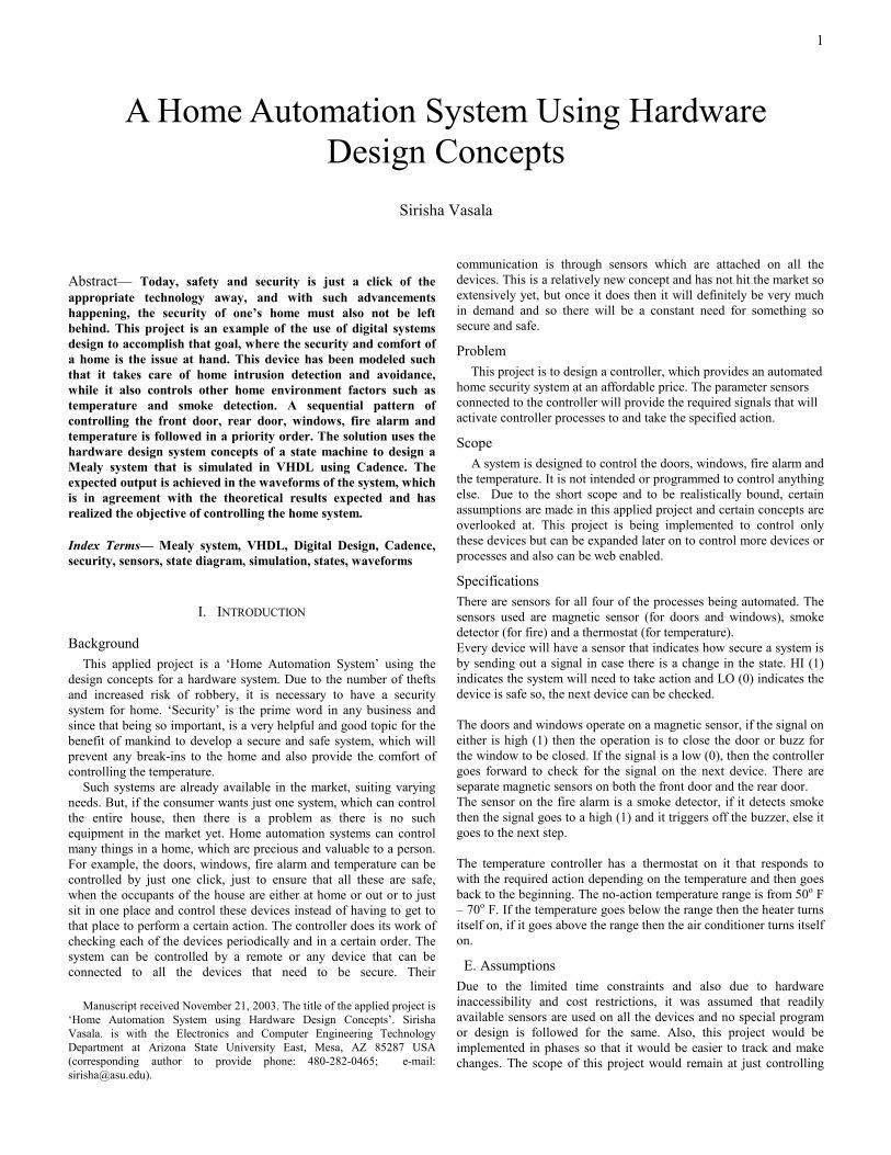
Approach Following the hardware design concepts, the first step taken in designing this system is to figure out what equipment needs to be secure. This is the initial stage wherein the devices that need to be connected for security are short-listed and then they are put in a network and so the corresponding work is done. The devices are doors (doors include front and rear doors), windows, fire alarm and the temperature controller. Draw the bare bones block diagram that relates to all the devices, the sensors used and the inputs and the outputs. The block diagram showing all the inputs and outputs is drawn thus making it clear what inputs are required to drive which outputs. As explained earlier, the signals on the attached sensors are captured and hence the required action is taken either on the same device or proceeds to the next device. The Block diagram of the controller is as shown below where, the input signals are, clk = clocks the device, enable = resets, I1 = signal from the sensor on the Front Door, I2 = signal from the sensor on the Rear Door, I3 = signal from the sensor on the Window, I4 = signal from the sensor on the Fire Alarm, I5 = signal from the sensor on the Temperature Controller. and the output signals are,
fdoor = HI -> close the front door, LO -> reset and wait for next command, rdoor = HI -> close the rear door, LO -> reset and wait for the next command, win = buzz if window is open, i.e. HI, alarm = buzz if fire alarm is on, i.e. HI, heat = if temperature is less than 50 F turn heater on, cool = if temperature is more than 70 F turn cooler on, disp = 3 digit display that shows which state the system is in.
Figure: Block Diagram
The next step after the block diagram is to obtain the flow diagram of the same showing the different states and conditions. Initially, a simple flowchart is drawn in which the conditions and the required action to be taken are mentioned and then the detailed flowchart follows, in which the states and the devices will be shown. The state diagram step is the next to follow in which all the states are shown and also see if the states can be reduced. A state diagram is developed that shows all the states and their behaviors. The states are examined for redundancy and reduced if any are found. This analysis and reduction helps to obtain a minimum and race free system. Simulate the system using VHDL and see if it is working efficiently. The tool used for this purpose is the Cadence nclaunch VHDL simulator. Based on the results obtained, the results are compared and verified with those that were assumed and hence the conclusions are obtained.
Sequence of Presentation This report gives an in-depth knowledge of the applied project and its functionality along with the limitations, advantages, conclusions, future development and other factors. The report is divided into chapters and each chapter deals with one part of the applied project. The current chapter in this report covers the introduction to the system and gives more details on how the problem is approached, concept, its scope, specifications and the assumptions made. The next chapter gives more details on what the project really is about, why VHDL was used for this. The use and development of controllers and circuits and secure systems along with some interesting facts on a Home Automation system and the design method and the approach for this project are other factors dealt with in Chapter 2. The state diagram showing the various states, the flowchart and description of the inputs and outputs are also given. Chapter 3 gives a complete and a detailed description on the VHDL code and testing. The results and simulation are covered in Chapter 4, and the conclusions and construction of final design are covered in Chapter 5.
CONTROLLER
clkenable
I1I2I3I4
I5(7 bit)
fdoorrdoor
winalarmheater cooler
disp(3bit)

3
II. THEORY
History of VHDL “VHDL development was initiated originally from the American Department of Defense (DoD). They requested a language for describing a hardware, which had to be readable for machines and humans at the same time and strictly forces the developer to write structured and comprehensible code, so that the source code itself can serve as a kind of specification document. Most important was the concept of concurrency to cope with the parallelism of digital hardware. Sequential statements to model very complex functions in a compact form were also allowed. ”In 1987, the American Institute of Electrical and Electronics Engineers (IEEE) standardized VHDL for the first time with the first official update in 1993. Apart from the file handling procedures these two versions of the standard are compatible. The standard of the language is described in the Language Reference Manual (LRM).” [1]. VHDL is the first standardized language that has been successful. Its predecessor language, Conlan of IFIP, was a failure.
What is VHDL? VHDL is an acronym for Very high speed integrated circuits Hardware Description Language. The term ‘hardware’ in VHDL includes a variety of systems from personal computers to the smallest logic gates on their internal integrated circuits. VHDL is used for the documentation, verification, and synthesis of very large and complex digital designs. Complex systems are described by the behavior that is observable from the outside. During the development cycle the description has to become more and more precise until it is actually possible to manufacture the product. The (automatic) transformation of a less detailed description into a more elaborated one is called synthesis. Existing synthesis tools are capable of mapping specific constructs of hardware description languages directly to the standard components of integrated circuits. This way, a formal model of the hardware system can be used from the early design studies to the final net list. Software support is available for the necessary refinement steps. VHDL consists of several components: - the actual VHDL language, - Data type declarations (package STANDARD), - Utility functions (package TEXTIO - text input-output), - User designs (package WORK), - STD Library, including packages STANDARD and TEXTIO, - vendor packages, - vendor libraries, user packages and libraries
Advantages of VHDL 1] VHDL is suitable for the design phases from system level to gate level. The first phase is the specification phase where the component to be designed is defined w.r.t. function, size, interfaces etc. Then self-contained modules are defined on the system level. Their interaction is described very precisely and interfaces (inputs, outputs, data formats), clock speed and reset mechanism are specified. Now the circuit can be simulated. Behavior models of standard components can be integrated into the system from libraries of commercial model developers. “On the logic level, the models that have to be designed are described with all the synthesis aspects in view. As long as only a certain subset of VHDL constructs is used,
commercial synthesis programs can derive the Boolean functions from this abstract model description and map them to the elements of an ASIC gate library or the configurable logic blocks of FPGAs. The result is a net list of the circuit or of the module on the gate level. Finally, the circuit layout for a specific ASIC technology can be created by means of other tools from the net list description.” [1]. Every transition to a lower abstraction level must be proven by functional validation. For this purpose, the description is simulated in such a way that for all stimuli (= input signals for the simulation) the module's responses are compared. 2] Reuse Capability: Hardware description languages offer design reuse capabilities. Similar to simple electronic components, like for example a resistor, the corresponding HDL model can be re-used in several designs/projects. It is common use that frequently needed function blocks (macros) are collected in model libraries. The selection of an existing module is not only restricted to the design engineer but can sometimes be performed by a synthesis tool. 3] Execution of code: The big advantage of hardware description languages is the possibility to actually execute the code. 4] Precise and Easy: During the development cycle the description has to become more and more precise until it is actually possible to manufacture the product. The (automatic) transformation of a less detailed description into a more elaborated one is called synthesis. Existing synthesis tools are capable of mapping specific constructs of hardware description languages directly to the standard components of integrated circuits. This way, a formal model of the hardware system can be used from the early design studies to the final net list. Software support is available for the necessary refinement steps.
Benefits 1] A language of big breadth: This allows one language to be used for the entire design process. A single designer knowing VHDL can design and simulate a complete system on many levels of description. 2] VHDL is a catalyst that allows designers to move up to an HDL design methodology. 3] Productive: Designer using VHDL becomes quickly much more productive than a classical designer who uses schematic capture, or point languages such as ABEL or CUPL since the design time is reduced. 4] Level of abstraction: VHDL allows designing on RTL (Register Transfer) level and behavioral level, thus the designer thinks on the design concept level rather on the component connecting level. 5] Improved quality of design: The user can easily modify the high-level description, thus exploring a larger area of solutions. 6] Technology independent design: The selection of technology can be delayed or changed in the last moment without any essential redesign.
Flow Diagram The bare bones block diagram was shown in the previous chapter, the corresponding flow diagram is given in the current chapter. The first state is the start state, in this state all the inputs and outputs are set to 0. Front door state: In this state the status of the front door is checked for and if the input from the magnetic sensor on the front door is 0

4
(LO) that indicates the door is closed, while if it is 1 (HI) then the door is open. If, I1 = 0 then the system goes to the next state else if I1 = 1 then the door is closed and the system goes to the next state which is the rear door state Rear door state: Just as in the front door state, the status of the rear door state is checked for first and if the input it receives from the magnetic sensor on the rear door is LO that means the door is closed, else the door is open. If, I2 = 0, then system goes to the next state, else if I2 = 1 then the rear door is closed and the system goes to the next state which is the window state. Window state: Here also, the status of the window is checked, LO indicates the window is closed, and HI means the window is open. The sensor on the window is a magnetic sensor. If I3 = 0, system goes to the next state, else if I3 = 1 then the window triggers off a buzzer and it keeps buzzing until it is manually turned off. The system in the meanwhile goes to the next state, which is the fire alarm state. Fire alarm state: The sensor here is the smoke detector and if it detects smoke then the input it sends is a 1 else it remains at 0. I4 = 0, the system goes to the next state meaning there is no fire, I4 = 1, means there is smoke and hence it triggers of a buzzer and goes to the next state which is the temperature state. The buzzer is on till it is manually turned off. Temperature controller state: This state has 3 conditions to fulfill based on the input it receives. The thermostat on the temperature regulator keeps checking the temperature of the room. If it goes below 50o F, then the system turns on the heater and if temperature goes beyond 70o F, then the air conditioner is turned on. Else the system goes back to the start state. The specifications for this state are as follows: I5 > 70o F, then turn on the air conditioner else if I5 < 50o F, then the heater is turned on. If the temperature is equal to 50o F or 70o F or anywhere between that span then no action is taken and the system goes back to the start state.
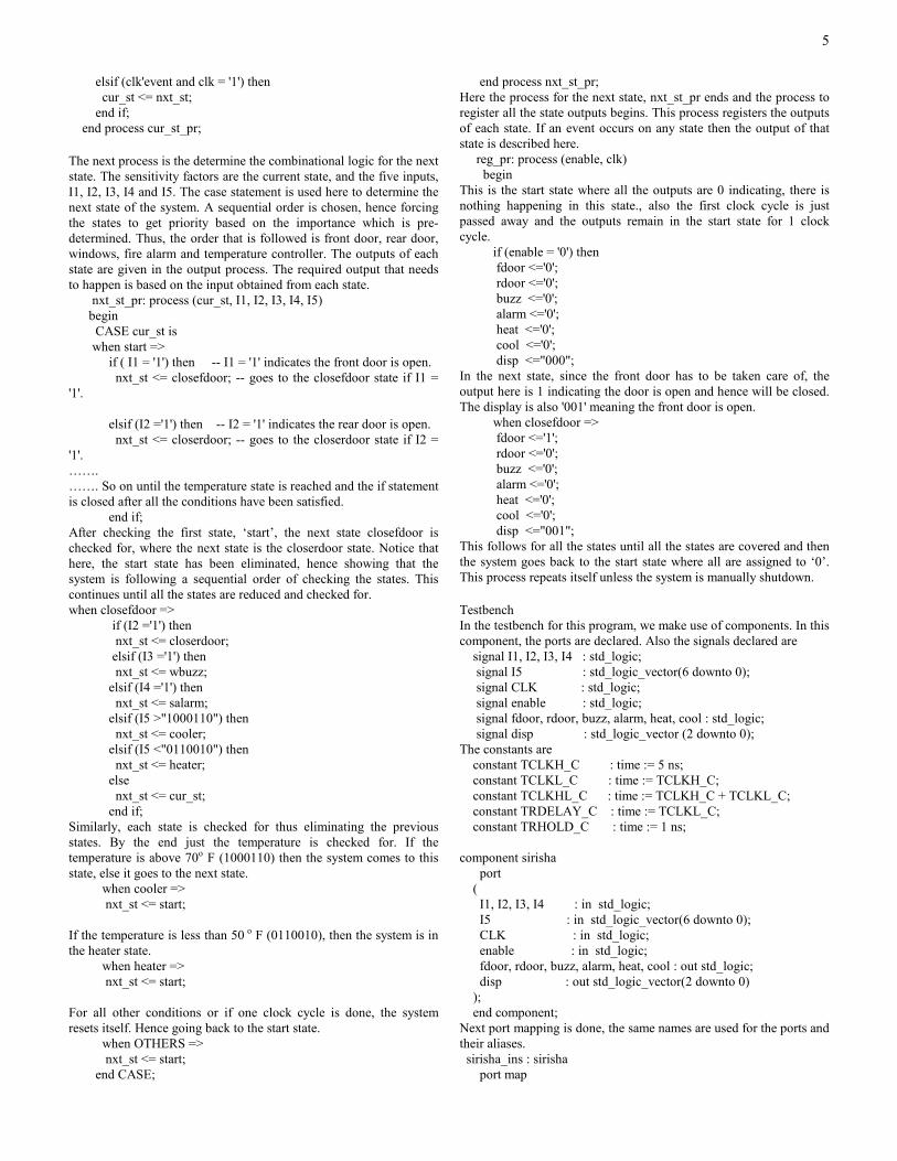
State Diagram I2 = 1/ z = 1 I3 = 1/ z = 1 I3 = 1/ z = 1 I1 = 1/ z = 1 I4= 1/ z = 1
I4= 1/ z = 1
I5 = 1000110 I5 = 0110010 = 0110010
Figure 3: State Diagram
cur_st nxt_st disp start closefdoor 0 closefdoor closerdoor 1 closerdoor wbuzz 2 wbuzz salarm 3 salarm heater 4 heater cooler 5 cooler start 6
Table: Current and next states
Thus, obtaining the state diagram depicting the various states, now we implement the design. The VHDL code for this state machine and the test bench is given in the next chapter, Chapter 3.
III. IMPLEMENTATION
Introduction In the previous chapter we discussed the design method, approach to the problem and the various states and the function of each state. This chapter deals with the details of the same and how the solution to the problem has been achieved. Emphasis is on the design and code part in this chapter. The details on the VHDL language and explanation on the code follows. This chapter is divided in sections, each devoted to the seven states and its corresponding inputs and outputs. There is also a test bench that allocates certain values to the inputs so that the output can be observed and compared to the theoretical output. VHDL Code A part of the VHDL code for the problem stated above is as below. Most of the code is self-explanatory, each and every process and state has been explained in detail as comments. The first part is the entity wherein all the inputs and outputs, which are the ports to the system are assigned . entity sirisha is port ( I1, I2, I3, I4 : in std_logic; I5 : in std_logic_vector(6 downto 0); CLK : in std_logic; enable : in std_logic; fdoor, rdoor, buzz, alarm, heat, cool : out std_logic; disp : out std_logic_vector(2 downto 0) ); end sirisha; Two signals cur_st and nxt_st are declared in the architecture where they depict the current state the system is in and the next state the system will enter into respectively. In the architecture, there are 3 processes, for the current state, for the next state and for the output. In the current state process if the enable is 0, the current state is at 'start'. If there is an event on clock or if clock is at 1, then the next state becomes the current state. The code for the same is cur_st_pr: process (clk, enable) begin if (enable = '0') then cur_st <= start;
start
fdoor
rdoor
salarm
wbuzz
cooler
Heater
5
elsif (clk'event and clk = '1') then cur_st <= nxt_st; end if; end process cur_st_pr; The next process is the determine the combinational logic for the next state. The sensitivity factors are the current state, and the five inputs, I1, I2, I3, I4 and I5. The case statement is used here to determine the next state of the system. A sequential order is chosen, hence forcing the states to get priority based on the importance which is pre-determined. Thus, the order that is followed is front door, rear door, windows, fire alarm and temperature controller. The outputs of each state are given in the output process. The required output that needs to happen is based on the input obtained from each state. nxt_st_pr: process (cur_st, I1, I2, I3, I4, I5) begin CASE cur_st is when start => if ( I1 = '1') then -- I1 = '1' indicates the front door is open. nxt_st <= closefdoor; -- goes to the closefdoor state if I1 = '1'. elsif (I2 ='1') then -- I2 = '1' indicates the rear door is open. nxt_st <= closerdoor; -- goes to the closerdoor state if I2 = '1'. ……. ……. So on until the temperature state is reached and the if statement is closed after all the conditions have been satisfied. end if; After checking the first state, ‘start’, the next state closefdoor is checked for, where the next state is the closerdoor state. Notice that here, the start state has been eliminated, hence showing that the system is following a sequential order of checking the states. This continues until all the states are reduced and checked for. when closefdoor => if (I2 ='1') then nxt_st <= closerdoor; elsif (I3 ='1') then nxt_st <= wbuzz; elsif (I4 ='1') then nxt_st <= salarm; elsif (I5 >"1000110") then nxt_st <= cooler; elsif (I5 <"0110010") then nxt_st <= heater; else nxt_st <= cur_st; end if; Similarly, each state is checked for thus eliminating the previous states. By the end just the temperature is checked for. If the temperature is above 70o F (1000110) then the system comes to this state, else it goes to the next state. when cooler => nxt_st <= start; If the temperature is less than 50 o F (0110010), then the system is in the heater state. when heater => nxt_st <= start; For all other conditions or if one clock cycle is done, the system resets itself. Hence going back to the start state. when OTHERS => nxt_st <= start; end CASE;
end process nxt_st_pr; Here the process for the next state, nxt_st_pr ends and the process to register all the state outputs begins. This process registers the outputs of each state. If an event occurs on any state then the output of that state is described here. reg_pr: process (enable, clk) begin This is the start state where all the outputs are 0 indicating, there is nothing happening in this state., also the first clock cycle is just passed away and the outputs remain in the start state for 1 clock cycle. if (enable = '0') then fdoor <='0'; rdoor <='0'; buzz <='0'; alarm <='0'; heat <='0'; cool <='0'; disp <="000"; In the next state, since the front door has to be taken care of, the output here is 1 indicating the door is open and hence will be closed. The display is also '001' meaning the front door is open. when closefdoor => fdoor <='1'; rdoor <='0'; buzz <='0'; alarm <='0'; heat <='0'; cool <='0'; disp <="001"; This follows for all the states until all the states are covered and then the system goes back to the start state where all are assigned to ‘0’. This process repeats itself unless the system is manually shutdown. Testbench In the testbench for this program, we make use of components. In this component, the ports are declared. Also the signals declared are signal I1, I2, I3, I4 : std_logic; signal I5 : std_logic_vector(6 downto 0); signal CLK : std_logic; signal enable : std_logic; signal fdoor, rdoor, buzz, alarm, heat, cool : std_logic; signal disp : std_logic_vector (2 downto 0); The constants are constant TCLKH_C : time := 5 ns; constant TCLKL_C : time := TCLKH_C; constant TCLKHL_C : time := TCLKH_C + TCLKL_C; constant TRDELAY_C : time := TCLKL_C; constant TRHOLD_C : time := 1 ns; component sirisha port ( I1, I2, I3, I4 : in std_logic; I5 : in std_logic_vector(6 downto 0); CLK : in std_logic; enable : in std_logic; fdoor, rdoor, buzz, alarm, heat, cool : out std_logic; disp : out std_logic_vector(2 downto 0) ); end component; Next port mapping is done, the same names are used for the ports and their aliases. sirisha_ins : sirisha port map

6
( I1 => I1, I2=> I2, I3=>I3, I4=>I4, I5=> I5, CLK=>CLK, enable => enable, fdoor =>fdoor, rdoor=>rdoor, buzz=>buzz, alarm=>alarm, heat=>heat, cool=>cool, disp=>disp ); The testbench code consists of three processes, enable_PR, CLK_PR and STIMULUS_PR. In enable_PR process, the process generates on enable. enable_PR : process begin enable <= '1'; wait for TRDELAY_C; enable <= '0'; wait until (CLK'event and CLK = '1'); wait until (CLK'event and CLK = '1'); wait for TRHOLD_C; enable <= '1'; wait; -- wait forever end process enable_PR; In the process CLK_PR, the system waits until the process generates on the clock. CLK_PR : process begin if (now = 0 ns) then CLK <= '0'; end if; wait for TCLKL_C; CLK <= '1'; wait for TCLKH_C; CLK <= '0'; end process CLK_PR; The third process STIMULUS_PR generates on the outputs and the simulation. STIMULUS_PR: process begin I1 <= '1'; I2 <= '0'; I3 <= '0'; I4 <= '0'; I5 <= "0000000"; wait until (clk ='1' and clk'event); I1 <= '0'; I2 <= '1'; I3 <= '0'; I4 <= '0'; I5 <= "0000000"; wait until (clk ='1' and clk'event); I1 <= '0'; I2 <= '0'; I3 <= '1'; I4 <= '0'; I5 <= "0000000"; wait until (clk ='1' and clk'event); I1 <= '0'; I2 <= '0'; I3 <= '0'; I4 <= '1'; I5 <= "0000000"; wait until (clk ='1' and clk'event); I1 <= '1'; I2 <= '0'; I3 <= '0'; I4 <= '0'; I5 <= "0000000"; wait until (clk ='1' and clk'event); --.....................=....................................... -- assert (FALSE) report --"End of Stimulus" -- severity failure; --wait; end process STIMULUS_PR; This marks the end of the code part. This code is then compiled using the Cadence ncLaunch tool for VHDL on a UNIX environment and then simulated. The steps for simuation, results and conclusions will be explained in the subsequent sections.
IV. RESULTS
Compilation The first step towards compiling is to launch the nclaunch tool using the nclaunch& command. This opens a window, the screen shot
of which is shown in the figure 4 below. This lists the files and when compiled it shows the work libraries created for the entity and the snapshots for the architecture that are created after elaborating the entity. The main file is first compiled and then the test bench file. The entity and architecture of the test bench are elaborated and simulated.
Figure 4 : nclaunch window
Simulation On simulating the file worklib_sirisha_tb:sirisha_tb_ar, a new window opens up which is shown in figure 5 . In this window, the code can be run. The next step here is to launch the Navigator which is done by clicking on Windows-> Navigator.
Figure 5: Simulator window
Navigator
The navigator window shows all the inputs, outputs and the signals to the system. All the parameters are selected here and the Waveform View is obtained. Clicking on the Waveform View button on the toolbar does this
7
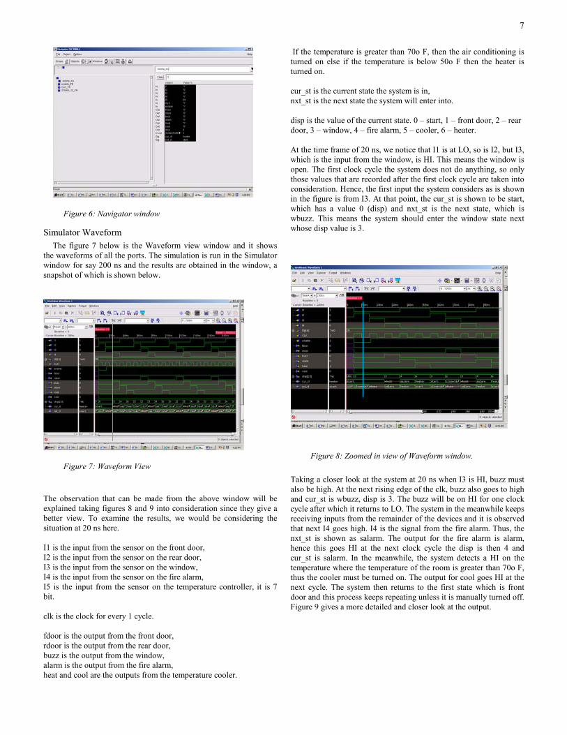
Figure 6: Navigator window
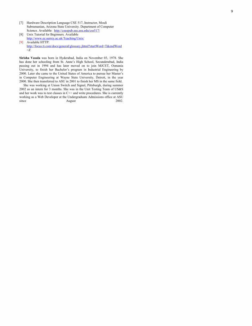
Simulator Waveform The figure 7 below is the Waveform view window and it shows the waveforms of all the ports. The simulation is run in the Simulator window for say 200 ns and the results are obtained in the window, a snapshot of which is shown below.
Figure 7: Waveform View The observation that can be made from the above window will be explained taking figures 8 and 9 into consideration since they give a better view. To examine the results, we would be considering the situation at 20 ns here. I1 is the input from the sensor on the front door, I2 is the input from the sensor on the rear door, I3 is the input from the sensor on the window, I4 is the input from the sensor on the fire alarm, I5 is the input from the sensor on the temperature controller, it is 7 bit. clk is the clock for every 1 cycle. fdoor is the output from the front door, rdoor is the output from the rear door, buzz is the output from the window, alarm is the output from the fire alarm, heat and cool are the outputs from the temperature cooler.
If the temperature is greater than 70o F, then the air conditioning is turned on else if the temperature is below 50o F then the heater is turned on. cur_st is the current state the system is in, nxt_st is the next state the system will enter into. disp is the value of the current state. 0 – start, 1 – front door, 2 – rear door, 3 – window, 4 – fire alarm, 5 – cooler, 6 – heater. At the time frame of 20 ns, we notice that I1 is at LO, so is I2, but I3, which is the input from the window, is HI. This means the window is open. The first clock cycle the system does not do anything, so only those values that are recorded after the first clock cycle are taken into consideration. Hence, the first input the system considers as is shown in the figure is from I3. At that point, the cur_st is shown to be start, which has a value 0 (disp) and nxt_st is the next state, which is wbuzz. This means the system should enter the window state next whose disp value is 3.
Figure 8: Zoomed in view of Waveform window. Taking a closer look at the system at 20 ns when I3 is HI, buzz must also be high. At the next rising edge of the clk, buzz also goes to high and cur_st is wbuzz, disp is 3. The buzz will be on HI for one clock cycle after which it returns to LO. The system in the meanwhile keeps receiving inputs from the remainder of the devices and it is observed that next I4 goes high. I4 is the signal from the fire alarm. Thus, the nxt_st is shown as salarm. The output for the fire alarm is alarm, hence this goes HI at the next clock cycle the disp is then 4 and cur_st is salarm. In the meanwhile, the system detects a HI on the temperature where the temperature of the room is greater than 70o F, thus the cooler must be turned on. The output for cool goes HI at the next cycle. The system then returns to the first state which is front door and this process keeps repeating unless it is manually turned off. Figure 9 gives a more detailed and closer look at the output.

8
Figure 9: Zoomed in view of Waveform window.
Figure 10: Zoomed in view of Waveform window.
Figure 11: Zoomed in view of Waveform window.
Results The objective of this project is to build the security system for the home giving priority to the doors and this has been achieved as shown above in the waveform view that shows the output. The inputs
are checked in the order I1, I2, I3, I4 and I5 and the corresponding outputs are obtained. ‘disp’ displays the state in which the system is currently. ‘cur_st’ shows the current state of the system and nxt_st shows the next state the system would enter. Thus, for every change in the input (HI) the output also changes (goes to HI) and thus implying the action is being taken.
Observations Working on this applied project has truly been an amazing experience, learning new stuff and also enhancing some VHDL coding skills along with logic implementation using real life situations. One important observation to make is though the situation depicted here is more hypothetical, efforts have been to put in to make it as practical as possible in the process, making a few assumptions such as the sensors already fitted on the devices.
V. CONCLUSIONS
Conclusions Concluding that the goal of this applied project has been reached, that is to design a controller, which provides an automated home security system at an affordable price. There have been many assumptions all through, but efforts have been put in to make it as practical as possible. The order of checking the devices based on the priority is followed and also the display shows the state the system is in. This is a low cost and effective device and with a few more changes it can be made a little more advance making it web enabled. This method is very easy to adapt and implement and can easily be embedded to another device. I would also want to point out here that using VHDL to implement the code part has really helped since it not only combines the hardware and software part, it also provides informative graphs and waveforms which are helpful in understanding the real concept of the project. Cadence also has proved to be the most robust and learnable tool for simulation.
Future work There are a few recommendations for making this system a marketable product. 1] Use the devices and the sensors and implement the hardware part. 2] Convert this into a high level language and write it onto a chip creating a device that can be embedded to a PC, laptop, palm top etc. 3] Make it web enabled to administer the system remotely. 4] Introduce a few more devices to control, for example the cooking range, water temperature control, garage doors, and lights etc.
REFERENCES [1] Zhaofeng, Z, “CMOS Radio Frequency Integrated Circuit Design for
Direct Conversion Receivers,” Hong-Kong-University-of-Science-and-Technology- People’s-Republic-of-China, 2001.
[2] Dewey, A. Analysis and Design of Digital System with VHDL. Boston, MA: PWS Publishing Company: 1997
[3] “Design of a Robot”, Available http://www.ee.pdx.edu/~mperkows/CLASS_VHDL_99/ SHIVO/robot_design.pdf
[4] Wobschall, D. Circuit Design for Electronic Instrumentation: Analog and Digital Devices from Sensor to Display, New York: McGraw-Hill, 1979.
[5] CSE 517: Hardware Description Language, Instructor, Dr. Karam S. Chatha, Arizona State University. Department of Computer Science. Available http://www.eas.asu.edu/~cse517a/
[6] VHDL Tutorial by Jan Van der Spiegel, University of Pennsylvania. Department of Electrical Engineering. Available: http://www.seas.upenn.edu/~ee201/vhdl/vhdl_primer.html#_Toc526061341
9
[7] Hardware Description Language CSE 517, Instructor, Mouli Subramanian, Arizona State University. Department of Computer Science. Available: http://ceaspub.eas.asu.edu/cse517/
[8] Unix Tutorial for Beginners. Available http://www.ee.surrey.ac.uk/Teaching/Unix/
[9] Available HTTP: http://focus.ti.com/docs/general/glossary.jhtml?startWord=T&endWord=Z
Sirisha Vasala was born in Hyderabad, India on November 03, 1978. She has done her schooling from St. Anne’s High School, Secunderabad, India passing out in 1994 and has later moved on to join MJCET, Osmania University, to finish her Bachelor’s program in Industrial Engineering by 2000. Later she came to the United States of America to pursue her Master’s in Computer Engineering at Wayne State University, Detroit, in the year 2000. She then transferred to ASU in 2001 to finish her MS in the same field. She was working at Union Switch and Signal, Pittsburgh, during summer 2002 as an intern for 3 months. She was in the Unit Testing Team of US&S and her work was to test classes in C++ and write procedures. She is currently working as a Web Developer at the Undergraduate Admissions office at ASU since August 2002.

10
Related Documents