IEEE TRANSACTIONS ON INDUSTRIAL ELECTRONICS, VOL. 59, NO. 9, SEPTEMBER 2012 3411 A High-Performance Sensorless Position Control System of a Synchronous Reluctance Motor Using Dual Current-Slope Estimating Technique Ming-Yen Wei and Tian-Hua Liu, Senior Member, IEEE Abstract—This paper proposes an adaptive sensorless position control system for a synchronous reluctance motor (SynRM). By using the proposed dual current-slope estimating technique, the rotor position of the SynRM can be precisely obtained. In addi- tion, a comparison which shows that the proposed dual current- slope method has better performance than the traditional single current-slope method is discussed. To improve the transient re- sponses and load disturbance rejection capability, an adaptive controller and a novel online self-tuning-gain state estimator are proposed here. A TMS-320F-28335 digital signal processor is used to execute the rotor position estimation, self-tuning-gain state estimation, adaptive control algorithm, d–q to a–b–c coordi- nate transformation, and PWM switching strategy. As a result, the hardware circuit is very simple. Experimental results show that the proposed system has satisfactory performance and good robustness. The estimated position error of the proposed dual current-slope estimating method can be reduced to 50% as com- pared to the traditional single current-slope position estimating method. Several experimental results are provided to validate the theoretical analysis. Index Terms—Adaptive position controller, digital signal processor (DSP), dual current-slope sensorless technique, online self-tuning-gain state estimator. I. I NTRODUCTION T HE synchronous reluctance motor (SynRM) has been recognized to have many advantages due to its simple and rugged structure. In addition, there is no winding or magnetic material on its rotor. The SynRM, therefore, is easy to man- ufacture. The SynRM has been shown to be very suitable for ac drive systems for several reasons. First, it is not necessary to compute the slip of the SynRM as it is with the induction motor. As a result, there is no parameter sensitivity problem. Next, it does not require any permanent magnetic material as the permanent-magnet synchronous motor does [1]–[6]. Moreover, the SynRM is more suitable for a sensorless drive due to its different d- and q-axes inductances. Rotor position estimating techniques have been investigated to reduce the cost of the rotor position sensor and to simplify the drive system. Several papers Manuscript received February 8, 2011; revised May 9, 2011 and August 13, 2011; accepted September 30, 2011. Date of publication December 8, 2011; date of current version April 13, 2012. The authors are with the National Taiwan University of Science and Technology, Taipei 106, Taiwan (e-mail: [email protected]; [email protected]). Color versions of one or more of the figures in this paper are available online at http://ieeexplore.ieee.org. Digital Object Identifier 10.1109/TIE.2011.2173093 have been published on estimating the rotor position of the SynRM. The first method is the extended back electromotive force (EMF) method, which is the most popular method for esti- mating the rotor position of a SynRM. This method, however, cannot be used in a low-speed range or standstill condition. Several papers have been published to discuss the rotor position estimating method by using the extended back EMF method. For example, Schroedl investigated two different algorithms that are used to calculate the rotor position of a SynRM [7]. In the low-speed range, the d- and q-axes inductances were online identified by using the measured currents and voltages. The rotor position, which is related to the inductances, was obtained. On the other hand, in the high-speed range, the back EMF of the motor was used to estimate the rotor position. This method, however, did not provide a unified algorithm for both low- and high-speed ranges. In addition, this method required a lot of computations due to its complexity. Guglielmi et al. investigated the impact of cross-saturation in sensorless control of the transverse-laminated SynRM [8]. In this paper, the flux observer was used for middle- and high-speed ranges. More- over, both the voltage and current sensors were required. As a result, the sensing circuit is too expensive and requires a lot of space as well. Consoli et al. proposed a sensorless torque con- trol of SynRM drives, which was a direct self-control scheme for SynRM drives. However, the implemented system exhibited serious torque pulsations due to its direct torque control method [9] As a result, the proposed system cannot be used for high- performance industrial applications. Zarchi et al. presented an adaptive input–output feedback linearization-based torque control of a SynRM without using a rotor position sensor [10]. The idea was very good. The paper used the switching states and the fixed dc-bus voltage command to compute the three- phase voltages. In the real world, the dc-bus voltage, however, is obviously varied as the load is changed. An estimating position error, therefore, can be increased. Ichikawa et al. proposed a sensorless control of the SynRM based on extended EMF models with online parameters. The computation processes of the extended EMF and the parameter identification, however, were very complicated [11]. Capecchi et al. proposed a position sensorless control of the transverse-laminated SynRM [12]. The paper used a combination of methods of rotor position estimation, including an EMF-based estimation and a signal injection method. In this paper, two combined methods were required. As a result, the transition between the two methods 0278-0046/$26.00 © 2011 IEEE

Welcome message from author
This document is posted to help you gain knowledge. Please leave a comment to let me know what you think about it! Share it to your friends and learn new things together.
Transcript
IEEE TRANSACTIONS ON INDUSTRIAL ELECTRONICS, VOL. 59, NO. 9, SEPTEMBER 2012 3411
A High-Performance Sensorless Position ControlSystem of a Synchronous Reluctance Motor Using
Dual Current-Slope Estimating TechniqueMing-Yen Wei and Tian-Hua Liu, Senior Member, IEEE
Abstract—This paper proposes an adaptive sensorless positioncontrol system for a synchronous reluctance motor (SynRM). Byusing the proposed dual current-slope estimating technique, therotor position of the SynRM can be precisely obtained. In addi-tion, a comparison which shows that the proposed dual current-slope method has better performance than the traditional singlecurrent-slope method is discussed. To improve the transient re-sponses and load disturbance rejection capability, an adaptivecontroller and a novel online self-tuning-gain state estimator areproposed here. A TMS-320F-28335 digital signal processor is usedto execute the rotor position estimation, self-tuning-gain stateestimation, adaptive control algorithm, d–q to a–b–c coordi-nate transformation, and PWM switching strategy. As a result,the hardware circuit is very simple. Experimental results showthat the proposed system has satisfactory performance and goodrobustness. The estimated position error of the proposed dualcurrent-slope estimating method can be reduced to 50% as com-pared to the traditional single current-slope position estimatingmethod. Several experimental results are provided to validate thetheoretical analysis.
Index Terms—Adaptive position controller, digital signalprocessor (DSP), dual current-slope sensorless technique, onlineself-tuning-gain state estimator.
I. INTRODUCTION
THE synchronous reluctance motor (SynRM) has beenrecognized to have many advantages due to its simple and
rugged structure. In addition, there is no winding or magneticmaterial on its rotor. The SynRM, therefore, is easy to man-ufacture. The SynRM has been shown to be very suitable forac drive systems for several reasons. First, it is not necessary tocompute the slip of the SynRM as it is with the induction motor.As a result, there is no parameter sensitivity problem. Next,it does not require any permanent magnetic material as thepermanent-magnet synchronous motor does [1]–[6]. Moreover,the SynRM is more suitable for a sensorless drive due to itsdifferent d- and q-axes inductances. Rotor position estimatingtechniques have been investigated to reduce the cost of the rotorposition sensor and to simplify the drive system. Several papers
Manuscript received February 8, 2011; revised May 9, 2011 andAugust 13, 2011; accepted September 30, 2011. Date of publicationDecember 8, 2011; date of current version April 13, 2012.
The authors are with the National Taiwan University of Science andTechnology, Taipei 106, Taiwan (e-mail: [email protected];[email protected]).
Color versions of one or more of the figures in this paper are available onlineat http://ieeexplore.ieee.org.
Digital Object Identifier 10.1109/TIE.2011.2173093
have been published on estimating the rotor position of theSynRM.
The first method is the extended back electromotive force(EMF) method, which is the most popular method for esti-mating the rotor position of a SynRM. This method, however,cannot be used in a low-speed range or standstill condition.Several papers have been published to discuss the rotor positionestimating method by using the extended back EMF method.For example, Schroedl investigated two different algorithmsthat are used to calculate the rotor position of a SynRM [7].In the low-speed range, the d- and q-axes inductances wereonline identified by using the measured currents and voltages.The rotor position, which is related to the inductances, wasobtained. On the other hand, in the high-speed range, the backEMF of the motor was used to estimate the rotor position. Thismethod, however, did not provide a unified algorithm for bothlow- and high-speed ranges. In addition, this method requireda lot of computations due to its complexity. Guglielmi et al.investigated the impact of cross-saturation in sensorless controlof the transverse-laminated SynRM [8]. In this paper, the fluxobserver was used for middle- and high-speed ranges. More-over, both the voltage and current sensors were required. As aresult, the sensing circuit is too expensive and requires a lot ofspace as well. Consoli et al. proposed a sensorless torque con-trol of SynRM drives, which was a direct self-control schemefor SynRM drives. However, the implemented system exhibitedserious torque pulsations due to its direct torque control method[9] As a result, the proposed system cannot be used for high-performance industrial applications. Zarchi et al. presentedan adaptive input–output feedback linearization-based torquecontrol of a SynRM without using a rotor position sensor [10].The idea was very good. The paper used the switching statesand the fixed dc-bus voltage command to compute the three-phase voltages. In the real world, the dc-bus voltage, however, isobviously varied as the load is changed. An estimating positionerror, therefore, can be increased. Ichikawa et al. proposeda sensorless control of the SynRM based on extended EMFmodels with online parameters. The computation processes ofthe extended EMF and the parameter identification, however,were very complicated [11]. Capecchi et al. proposed a positionsensorless control of the transverse-laminated SynRM [12].The paper used a combination of methods of rotor positionestimation, including an EMF-based estimation and a signalinjection method. In this paper, two combined methods wererequired. As a result, the transition between the two methods
0278-0046/$26.00 © 2011 IEEE

3412 IEEE TRANSACTIONS ON INDUSTRIAL ELECTRONICS, VOL. 59, NO. 9, SEPTEMBER 2012
was a problem. Caporal et al. proposed an encoderless pre-dictive direct torque control for the SynRM at very low speedand zero speed; unfortunately, the injecting signal was requiredto detect the spatial orientations of existing position-dependentrotor anisotropies [13]. Foo et al. proposed a novel stator fluxobserver to estimate the stator flux and then to control the directtorque of the SynRM. This method, however, was only used inmiddle- to high-speed ranges. In fact, it could not be used forstandstill or for a low-speed operating range [14].
Recently, the second method, the high-frequency injectionmethod, has been used to detect the rotor position of theSynRM. The rotor position of the SynRM was obtained, inparticular, in the low-speed operating range and standstill con-dition. For example, Ha et al. proposed injecting the d-axis sta-tor current and then appropriately demodulating its signal. Therotor position was obtained as the motor was operated in thelow-speed operating range. This method, unfortunately, couldnot be used for high-speed operating ranges [15]. Kang et al.proposed using high-frequency current injection to operatethe SynRM from standstill to 300 r/min [16]. Consoli et al.presented the low- and zero-speed sensorless controls of theSynRM by injecting a high-frequency stator current. This re-search, unfortunately, only focused on zero- and low-speedoperating ranges [17]. Kock compared the anisotropy of reluc-tance and permanent-magnet synchronous motors for positionsensorless control by using a high-frequency injecting signal[18]. Again, this paper only focused on standstill and on a low-speed operating range. Consoli presented a new rotor positionestimation for the SynRM. A robust rotor position tracking wasobtained by adjusting the direction of the carrier voltage inorder to minimize the amplitude of the generated orthogonalvoltage. By using the carrier voltage, the proposed systemworked well for the low-speed operating range only [19].
The third method is used to estimate the rotor position of theSynRM by using the stator current-slope. For example, Matsuoand Lipo implemented a rotor position estimator by measuringthe rate change of the stator currents of the SynRM [20].This method performed well at a low speed. Unfortunately, theposition estimator deteriorated as the speed of the motor wasincreased. A compensator, therefore, was required. This com-pensator was related to the motor speeds and initial currents.As a result, it was a 3-D compensator, which was very difficultto design due to its nonlinear characteristics. Rahman et al.proposed an interesting method to estimate the position of aplunger inside a solenoid. The position was estimated indirectlythrough the solenoid’s incremental inductance in the high-current region. In fact, the incremental inductance was obtainedfrom the rate of current rise of the pulsewidth modulatedwaveform [21]. The results were good. However, although itwas suitable for solenoid, it was not for a SynRM.
Several years ago, Chen et al. and Lin et al. proposed aback EMF compensation technique by detecting the current-slope during the free-wheeling period. By using this method,the operating range was achieved from standstill to rated speed[22], [23]. This method, unfortunately, had an estimated er-ror of near ±2 mechanical degrees for the adjustable speedcontrol. To improve the estimated error, a dual current-slopetechnique and an online self-tuning-gain estimator are proposed
in this paper. The proposed method has some good aspects.Its estimated error is reduced to below ±1 mechanical degreefor the adjustable speed control. It does not require any extrahardware when compared to the SynRM control system withan attached encoder. The major reason is that the dual current-slope is computed by the digital signal processor (DSP). Inaddition, the proposed control system can start automaticallyfrom standstill. The proposed rotor estimating method can beused for a wide adjustable speed control system from 1 to1800 r/min and a precise position control system. To the bestof the authors’ knowledge, the proposed idea is new, and it iseasily applied in real industrial applications because no extrahardware is required.
II. MATHEMATICAL MODEL OF THE SynRM
To clearly explain the dual current-slope technique, theSynRM dynamic mathematical model in the a–b–c axis station-ary reference frame is used here. The three-phase voltage of theSynRM can be described by the following equations [24]:
vas = rsias +d
dtλas (1)
vbs = rsibs +d
dtλbs (2)
vcs = rsics +d
dtλcs (3)
where vas, vbs, and vcs are the stator voltages of the motor;rs is the stator resistance; ias, ibs, and ics are the stator cur-rents; λas, λbs, and λcs are the stator three-phase fluxes; andd/dt is the operator of the differential. The three-phase self-inductances are expressed as
λas = (Lls + LA + LB cos(2θre)) ias
+(−1
2LA + LB cos
(2θre −
23π
))ibs
+(−1
2LA + LB cos
(2θre +
23π
))ics (4)
λbs =(−1
2LA + LB cos
(2θre −
23π
))ias
+(
Lls + LA + LB cos(
2θre +23π
))ibs
+(−1
2LA + LB cos(2θre)
)ics (5)
λcs =(−1
2LA + LB cos
(2θre +
23π
))ias
+(−1
2LA + LB cos(2θre)
)ibs
+(
Lls + LA + LB cos(2θre −23π)
)ics (6)
where Lls is the leakage inductance, LA is the average value ofthe self-inductance, and LB is the amplitude of the sinusoidal
WEI AND LIU: HIGH-PERFORMANCE SENSORLESS POSITION CONTROL SYSTEM OF A SYNRM 3413
variation about this average value. The self-inductances andmutual inductances are not constant values and vary with thestator currents ias, ibs, and ics due to the saturated influence.θre is the electrical angle of the rotor position.
It is very difficult to express the electromagnetic torqueequation in the a–b–c stationary frame. As a result, a coordinatetransform is required here. After the a–b–c to d–q coordinatetransform, the flux linkages can be expressed as
λds = Ldids (7)
λqs = Lqiqs (8)
Ld = Lls +32(LA + LB) (9)
Lq = Lls +32(LA − LB) (10)
where λds is the d-axis flux linkage, λqs is the q-axis fluxlinkage, Ld is the d-axis inductance, Lq is the q-axis inductance,ids is the d-axis current, and iqs is the q-axis current.
The electromagnetic torque expressed in the d–q synchro-nous frame is
Te =32
P
2(λdsiqs − λqsids) =
32
P
2(3LB)idsiqs (11)
where Te is the electromagnetic torque of the motor and P isthe number of poles of the motor.
Then, the rotor speed of the motor is expressed as
d
dtωrm =
1Jm
(Te − TL − Bmωrm). (12)
The rotor position of the motor can be expressed as
d
dtθrm = ωrm (13)
where ωrm is the mechanical rotor speed, Jm is the inertiaconstant of the motor and load, TL is the external load torque,Bm is the viscous coefficient of the motor and load, and θrm isthe mechanical rotor position. The electrical rotor speed is
ωre =P
2ωrm. (14)
The electrical rotor position is
θre =P
2θrm. (15)
After that, by doing some mathematical processes, one canobtain⎡⎣ vas
vbs
vcs
⎤⎦ =
⎡⎣ rs 0 0
0 rs 00 0 rs
⎤⎦
⎡⎣ ias
ibs
ics
⎤⎦
+d
dt
⎡⎣Lq 0 0
0 Lq 00 0 Lq
⎤⎦
⎡⎣ ias
ibs
ics
⎤⎦ +
d
dt
⎡⎣ λe
a
λeb
λec
⎤⎦ (16)
where λea, λe
b , and λec are the a-, b-, and c-phase extended fluxes
of the SynRM.
The extended flux linkages can be expressed as follows:
λea =
{(−1
2LA +
32LB + LB cos(2θre)
)ias
+(−1
2LA + LB cos
(2θre −
2π
3
))ibs
+(−1
2LA + LB cos
(2θre +
2π
3
))ics
}(17)
λeb =
{(−1
2LA − 2LB cos(2θre)
)ias
+(−1
2LA +
32LB − 2LB cos(2θre)
−√
3LB sin(2θre))
ibs
+(−1
2LA + LB cos
(2θre +
2π
3
))ics
}(18)
λec =
{(−1
2LA − 2LB cos(2θre)
)ias
+(−1
2LA +
32LB − 2LB cos(2θre)
+√
3LB sin(2θre))
ics
+(−1
2LA + LB cos
(2θre −
2π
3
))ibs
}. (19)
From (17)–(19), we can define the following new symbolsfor the inductances:
LAA = − 12LA +
32LB + LB cos(2θre) (20)
LAB = LCB = −12LA + LB cos
(2θre −
2π
3
)(21)
LAC = LBC = −12LA + LB cos
(2θre +
2π
3
)(22)
LBA = LCA = −12LA − 2LB cos(2θre) (23)
LBB = − 12LA +
32LB − 2LB cos(2θre)
−√
3LB sin(2θre) (24)
LCC = − 12LA +
32LB − 2LB cos(2θre)
+√
3LB sin(2θre). (25)
III. DUAL CURRENT-SLOPE SENSORLESS TECHNIQUE
Chen et al. and Lin et al. proposed a single current-slopesensorless technique several years ago. To improve the accuracyof the estimated rotor position, a dual current-slope sensorlesstechnique is developed in this paper. The detailed principle,
3414 IEEE TRANSACTIONS ON INDUSTRIAL ELECTRONICS, VOL. 59, NO. 9, SEPTEMBER 2012
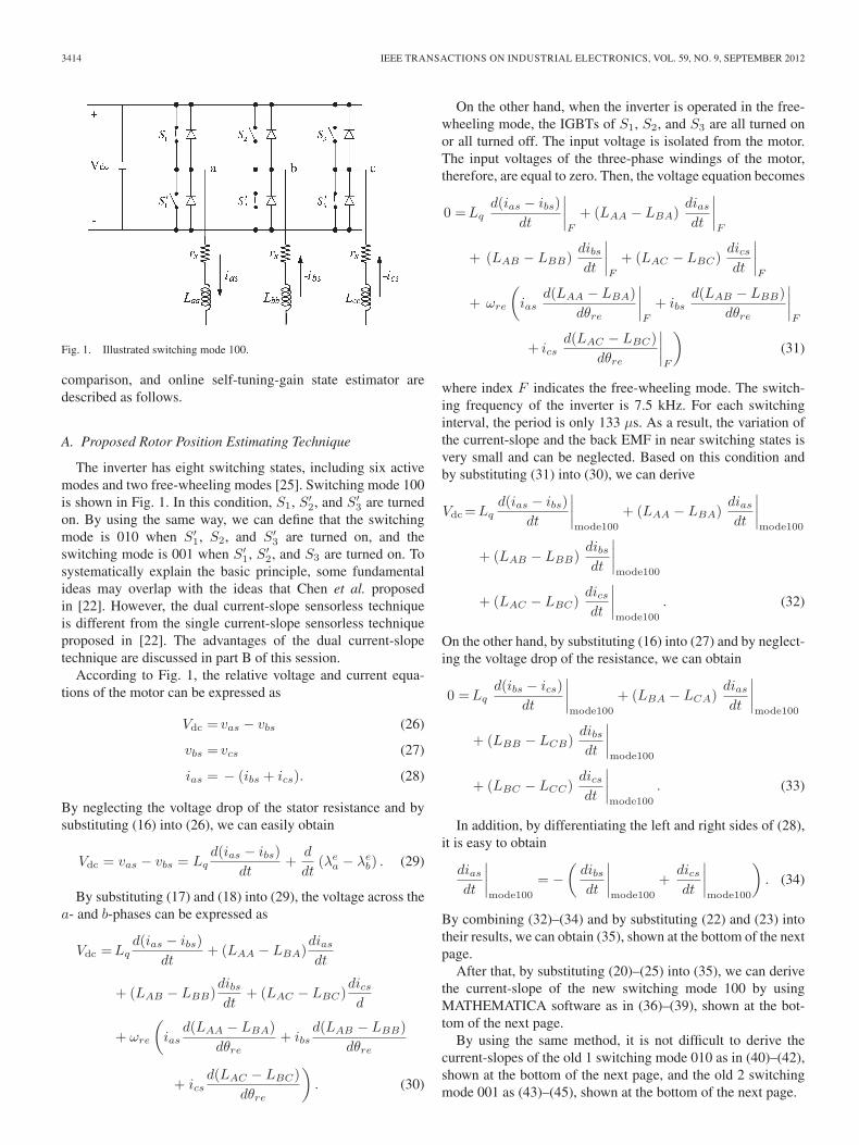
Fig. 1. Illustrated switching mode 100.
comparison, and online self-tuning-gain state estimator aredescribed as follows.
A. Proposed Rotor Position Estimating Technique
The inverter has eight switching states, including six activemodes and two free-wheeling modes [25]. Switching mode 100is shown in Fig. 1. In this condition, S1, S ′
2, and S ′3 are turned
on. By using the same way, we can define that the switchingmode is 010 when S ′
1, S2, and S ′3 are turned on, and the
switching mode is 001 when S ′1, S ′
2, and S3 are turned on. Tosystematically explain the basic principle, some fundamentalideas may overlap with the ideas that Chen et al. proposedin [22]. However, the dual current-slope sensorless techniqueis different from the single current-slope sensorless techniqueproposed in [22]. The advantages of the dual current-slopetechnique are discussed in part B of this session.
According to Fig. 1, the relative voltage and current equa-tions of the motor can be expressed as
Vdc = vas − vbs (26)
vbs = vcs (27)
ias = − (ibs + ics). (28)
By neglecting the voltage drop of the stator resistance and bysubstituting (16) into (26), we can easily obtain
Vdc = vas − vbs = Lqd(ias − ibs)
dt+
d
dt(λe
a − λeb) . (29)
By substituting (17) and (18) into (29), the voltage across thea- and b-phases can be expressed as
Vdc =Lqd(ias − ibs)
dt+ (LAA − LBA)
dias
dt
+ (LAB − LBB)dibs
dt+ (LAC − LBC)
dics
d
+ ωre
(ias
d(LAA − LBA)dθre
+ ibsd(LAB − LBB)
dθre
+ icsd(LAC − LBC)
dθre
). (30)
On the other hand, when the inverter is operated in the free-wheeling mode, the IGBTs of S1, S2, and S3 are all turned onor all turned off. The input voltage is isolated from the motor.The input voltages of the three-phase windings of the motor,therefore, are equal to zero. Then, the voltage equation becomes
0 =Lqd(ias − ibs)
dt
∣∣∣∣F
+ (LAA − LBA)dias
dt
∣∣∣∣F
+ (LAB − LBB)dibs
dt
∣∣∣∣F
+ (LAC − LBC)dics
dt
∣∣∣∣F
+ ωre
(ias
d(LAA − LBA)dθre
∣∣∣∣F
+ ibsd(LAB − LBB)
dθre
∣∣∣∣F
+ icsd(LAC − LBC)
dθre
∣∣∣∣F
)(31)
where index F indicates the free-wheeling mode. The switch-ing frequency of the inverter is 7.5 kHz. For each switchinginterval, the period is only 133 μs. As a result, the variation ofthe current-slope and the back EMF in near switching states isvery small and can be neglected. Based on this condition andby substituting (31) into (30), we can derive
Vdc = Lqd(ias − ibs)
dt
∣∣∣∣mode100
+ (LAA − LBA)dias
dt
∣∣∣∣mode100
+ (LAB − LBB)dibs
dt
∣∣∣∣mode100
+ (LAC − LBC)dics
dt
∣∣∣∣mode100
. (32)
On the other hand, by substituting (16) into (27) and by neglect-ing the voltage drop of the resistance, we can obtain
0 =Lqd(ibs − ics)
dt
∣∣∣∣mode100
+ (LBA − LCA)dias
dt
∣∣∣∣mode100
+ (LBB − LCB)dibs
dt
∣∣∣∣mode100
+ (LBC − LCC)dics
dt
∣∣∣∣mode100
. (33)
In addition, by differentiating the left and right sides of (28),it is easy to obtain
dias
dt
∣∣∣∣mode100
= −(
dibs
dt
∣∣∣∣mode100
+dics
dt
∣∣∣∣mode100
). (34)
By combining (32)–(34) and by substituting (22) and (23) intotheir results, we can obtain (35), shown at the bottom of the nextpage.
After that, by substituting (20)–(25) into (35), we can derivethe current-slope of the new switching mode 100 by usingMATHEMATICA software as in (36)–(39), shown at the bot-tom of the next page.
By using the same method, it is not difficult to derive thecurrent-slopes of the old 1 switching mode 010 as in (40)–(42),shown at the bottom of the next page, and the old 2 switchingmode 001 as (43)–(45), shown at the bottom of the next page.
WEI AND LIU: HIGH-PERFORMANCE SENSORLESS POSITION CONTROL SYSTEM OF A SYNRM 3415
To simplify the symbols, we can define the differ-ence in the current-slopes Dias|new_old1, Dibs|new_old1, andDics|new_old2 as follows:
⎡⎣Dias|mode100_mode010
Dibs|mode100_mode010
Dics|mode100_mode001
⎤⎦
=
⎡⎣
(dias
dt
)∣∣mode100
−(
dias
dt
)∣∣mode010(
dibs
dt
)∣∣mode100
−(
dibs
dt
)∣∣mode010(
dics
dt
)∣∣mode100
−(
dics
dt
)∣∣mode001
⎤⎦ . (46)
In (46), Dics|new_old2 uses old 2 to replace old 1 to avoidthe difficulty of dividing by zero. By substituting (36)–(38)and (40)–(45) into (46) and then by doing some coordinationtransformation, we can obtain
⎡⎣ Dias|mode100_mode010
Dibs|mode100_mode010
Dics|mode100_mode001
⎤⎦ =
⎡⎣
92 − 3
√3
2 −30 3
√3 3
0 −3√
3 3
⎤⎦
×
⎡⎣ Diα
DiβK · DC
⎤⎦ (46a)
⎡⎣ Vdc
00
⎤⎦ =
⎡⎣LAA − LBA + Lq LAB − LBB − Lq 0
0 LBB − LCB + Lq LBC − LCC − Lq
1 1 1
⎤⎦
⎡⎣ (dias/dt)|mode100
(dibs/dt)|mode100
(dics/dt)|mode100
⎤⎦ (35)
dias
dt
∣∣∣∣mode100
=(−3LB − 2Lq + 3LB cos(2θre)) Vdc
Δ(36)
dibs
dt
∣∣∣∣mode100
=
(32LB + Lq + 3
√3
2 LB sin(2θre) − 32LB cos(2θre)
)Vdc
Δ(37)
dics
dt
∣∣∣∣mode100
=
(32LB + Lq − 3
√3
2 LB sin(2θre) − 32LB cos(2θre)
)Vdc
Δ(38)
Δ =34
[−12LBLq − 4L2
q
](39)
dias
dt
∣∣∣∣mode010
=
(32LB + Lq + 3
√3
2 LB sin(2θre) − 32LB cos(2θre)
)Vdc
Δ(40)
dibs
dt
∣∣∣∣mode010
=
(−3LB − 2Lq − 3
√3
2 LB sin(2θre) − 32LB cos(2θre)
)Vdc
Δ(41)
dics
dt
∣∣∣∣mode010
=
(32LB + Lq + 3LB cos(2θre)
)Vdc
Δ(42)
dias
dt
∣∣∣∣mode001
=
(32LB + Lq − 3
√3
2 LB sin(2θre) − 32LB cos(2θre)
)Vdc
Δ(43)
dibs
dt
∣∣∣∣mode001
=
(32LB + Lq + 3LB cos(2θre)
)Vdc
Δ(44)
dics
dt
∣∣∣∣mode001
=
(−3LB − 2Lq + 3
√3
2 LB sin(2θre) − 32LB cos(2θre)
)Vdc
Δ(45)

3416 IEEE TRANSACTIONS ON INDUSTRIAL ELECTRONICS, VOL. 59, NO. 9, SEPTEMBER 2012
K =Vdc
Δ(47)
DC =32LB + Lq. (48)
From (46a), it is not difficult to obtain
⎡⎣ Diα
DiβK · DC
⎤⎦ =
⎡⎢⎣
92 − 3
√3
2 −3
0 3√
3 30 −3
√3 3
⎤⎥⎦−1
×
⎡⎢⎣
Dias|mode100_mode010
Dibs|mode100_mode010
Dics|mode100_mode001
⎤⎥⎦ . (49)
Next, by substituting (36)–(41) and (45) into (49), Diα and Diβcan be shown as
Diα =4VdcLB cos(2θre)
3[−12LBLq − 4L2
q
] (50)
Diβ =4VdcLB sin(2θre)
3[−12LBLq − 4L2
q
] . (51)
The rotor angle, finally, can be obtained as follows:
θre =12
tan−1
(DiβDiα
). (52)
From (50)–(52), we can observe that the current-slopes Diαand Diβ are related to the dc-bus voltage, the inductancesof the motor, and the rotor position. However, after a simplemathematical process, we can see that the ratio of Diα and Diβ ,which is shown in (52), is only related to the rotor position. As aresult, the influences of the voltage Vdc and the saturation of theinductances disappear. Moreover, no voltage sensor is requiredhere.
In the proposed system, the current-slope is obtained byonline measuring and not by using the mathematical model ofthe SynRM. However, to avoid the current spike, the samplinginstance is critical. The details are shown as follows. First, theDSP reads the stator current through A/D converters and Hall-effect current sensors to compute the current-slope of the statorcurrent. Then, the DSP executes the coordinate transformation,as shown in (49). After that, the rotor position of the motorcan be obtained by using the arc tangent mathematical processshown in (52). The online sampling technique of the statorcurrent is very important and is shown in Fig. 2(a). To computethe current-slope, two sampling points are required. Generallyspeaking, the DSP sends a trigger signal to turn on the IGBT.Then, the stator current changes. After a few microseconds, attime TS1, the DSP reads the first sampling point of the statorcurrent. At time TS2, the DSP reads the second sampling pointof the stator current. Time TS2 is set before the DSP sends thetrigger signal to turn off the IGBT. By using this measuringtechnique, the stator current can be precisely measured, andthen, the current-slope of the stator current can be easily
Fig. 2. Stator current sampling techniques. (a) Measured waveform.(b) Trigger signal.
computed. Fig. 2(b) shows the real experimental measuringresult of the stator current by using the proposed method. Foreach switching state, a 133-μs time interval is required, whichis enough for the DSP to read two currents and execute therequired current-slope and its related rotor position estimatingtechnique.
Although this paper and [7] look very similar, they aredifferent in many ways. First, Schroedl proposed a “complexinductance,” which is not the real inductance to estimate therotor position of a SynRM. This paper, however, can compute a“real inductance” to estimate the rotor position of a SynRM.Second, in [7], Schroedl used voltage sensors to detect thestator voltages and current sensors to detect the stator currents.Both of them are required to estimate the rotor position of aSynRM. In this paper, only current sensors are required, andthe voltage sensors are not used here. Next, in [7], the current-slope method was used for standstill and low-speed range. Inthis paper, the proposed dual current-slope method can be usedfrom standstill to rated speed. According to the aforementioneddiscussions, we can conclude that, compared to [7], the pro-posed method in this paper has many advantages, includinglow cost, wider operating range, and strong relationship to thereal inductances.
B. Comparison of Proposed and Single Current-Slope Method
When the inverter is operated in the active mode, thea-phase voltage is a nonzero voltage. In this situation, the motoris operated in any mode, except the zero-voltage vector mode.Take the following example to explain the basic idea. Whenswitching mode 100 is selected first and then switching mode010 is selected next, if the inverter is operated at mode 100, thea-phase voltage is expressed as
vas =23Vdc. (53)
By substituting (53) into (1) and (4) and by neglecting thevoltage drop of the resistance, we can obtain the a-phase
WEI AND LIU: HIGH-PERFORMANCE SENSORLESS POSITION CONTROL SYSTEM OF A SYNRM 3417
current-slope as
dias
dt
∣∣∣∣mode100
=23Vdc −
(Lab
dibs
dt
∣∣mode100
+ Lacdics
dt
∣∣mode100
)Laa
. (54)
The b- and c-phase current-slopes can be expressed as
dibs
dt
∣∣∣∣mode100
=dics
dt
∣∣∣∣mode100
= −12
dias
dt
∣∣∣∣mode100
. (55)
By substituting (55) into (54), we can obtain
dibs
dt
∣∣∣∣mode100
=dics
dt
∣∣∣∣mode100
=− 1
3Vdc+ 12
(Lab
dibs
dt
∣∣mode100
+Lacdics
dt
∣∣mode100
)Laa
.
(56)
Similarly, when the motor is operated in mode B+, the b-phasevoltage is expressed as
vbs =23Vdc. (57)
By substituting (57) into (2) and (5) and by neglecting the volt-age drop in the resistance, we can obtain the b-phase current-slope as
dibs
dt
∣∣∣∣mode010
=23Vdc −
(Lba
dias
dt
∣∣mode010
+ Lbcdics
dt
∣∣mode010
)Lbb
. (58)
Then, the a- and c-phase current-slopes are expressed as
dias
dt
∣∣∣∣mode010
=dics
dt
∣∣∣∣mode010
= −12
dibs
dt
∣∣∣∣mode010
. (59)
By substituting (59) into (58), we can obtain
dias
dt
∣∣∣∣mode010
=dics
dt
∣∣∣∣mode010
=− 1
3Vdc+ 12
(Lba
dias
dt
∣∣mode010
+Lbcdics
dt
∣∣mode010
)Lbb
. (60)
Generally speaking, the mutual inductance is very small andcan be neglected [26]. According to (54), (56), (58), and (60)and letting Laa = Lbb = Lcc, we can derive
Dias|mode100_mode010 =Vdc
Laa(61)
Dibs|mode100_mode010 =−Vdc
Lbb. (62)
From (54), (56), (61) and (62) and by neglecting the mu-tual inductance, the dual current-slope satisfies the followingrelationship:
Dias|mode100_mode010∼= 3
2dias
dt
∣∣∣∣mode100
(63)
Dibs|mode100_mode010∼= 3
dibs
dt
∣∣∣∣mode100
. (64)
The c-phase current-slope can be analyzed by using the samemethod. It can be expressed as
Dics|mode100_mode010∼= 3
dics
dt
∣∣∣∣mode100
. (65)
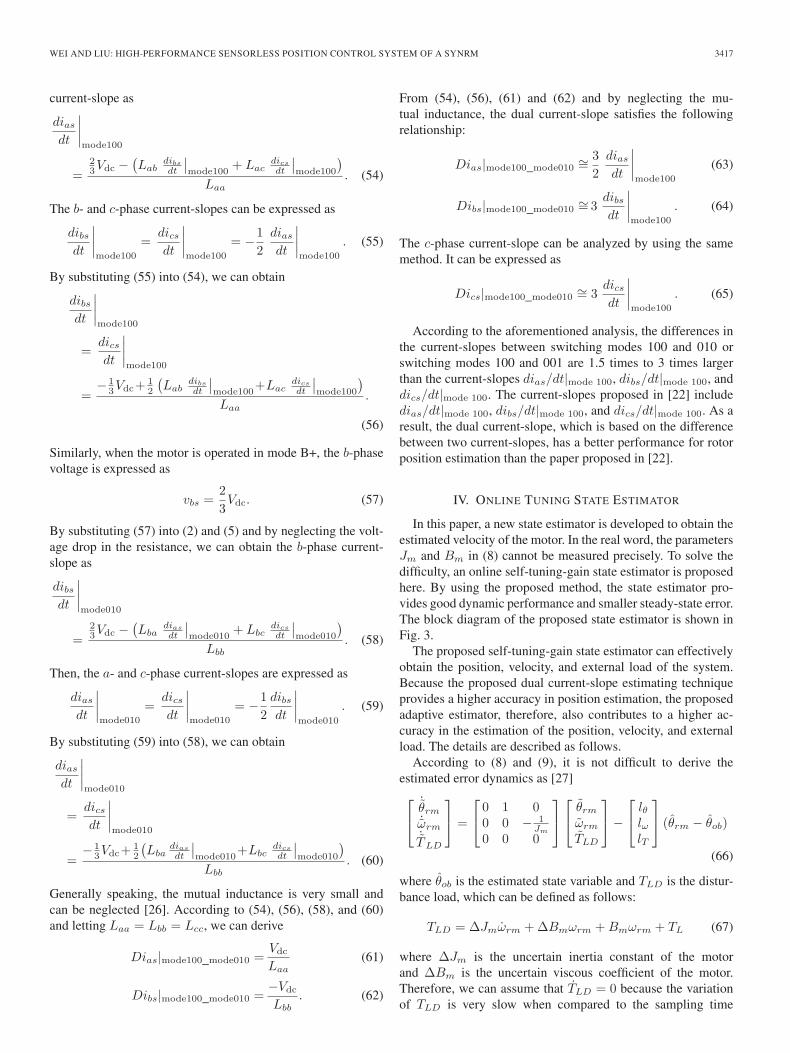
According to the aforementioned analysis, the differences inthe current-slopes between switching modes 100 and 010 orswitching modes 100 and 001 are 1.5 times to 3 times largerthan the current-slopes dias/dt|mode 100, dibs/dt|mode 100, anddics/dt|mode 100. The current-slopes proposed in [22] includedias/dt|mode 100, dibs/dt|mode 100, and dics/dt|mode 100. As aresult, the dual current-slope, which is based on the differencebetween two current-slopes, has a better performance for rotorposition estimation than the paper proposed in [22].
IV. ONLINE TUNING STATE ESTIMATOR
In this paper, a new state estimator is developed to obtain theestimated velocity of the motor. In the real word, the parametersJm and Bm in (8) cannot be measured precisely. To solve thedifficulty, an online self-tuning-gain state estimator is proposedhere. By using the proposed method, the state estimator pro-vides good dynamic performance and smaller steady-state error.The block diagram of the proposed state estimator is shown inFig. 3.
The proposed self-tuning-gain state estimator can effectivelyobtain the position, velocity, and external load of the system.Because the proposed dual current-slope estimating techniqueprovides a higher accuracy in position estimation, the proposedadaptive estimator, therefore, also contributes to a higher ac-curacy in the estimation of the position, velocity, and externalload. The details are described as follows.
According to (8) and (9), it is not difficult to derive theestimated error dynamics as [27]⎡⎣
˙θrm˙ωrm˙TLD
⎤⎦ =
⎡⎣ 0 1 0
0 0 − 1Jm
0 0 0
⎤⎦
⎡⎣ θrm
ωrm
TLD
⎤⎦ −
⎡⎣ lθ
lωlT
⎤⎦ (θrm − θob)
(66)
where θob is the estimated state variable and TLD is the distur-bance load, which can be defined as follows:
TLD = ΔJmωrm + ΔBmωrm + Bmωrm + TL (67)
where ΔJm is the uncertain inertia constant of the motorand ΔBm is the uncertain viscous coefficient of the motor.Therefore, we can assume that TLD = 0 because the variationof TLD is very slow when compared to the sampling time
3418 IEEE TRANSACTIONS ON INDUSTRIAL ELECTRONICS, VOL. 59, NO. 9, SEPTEMBER 2012
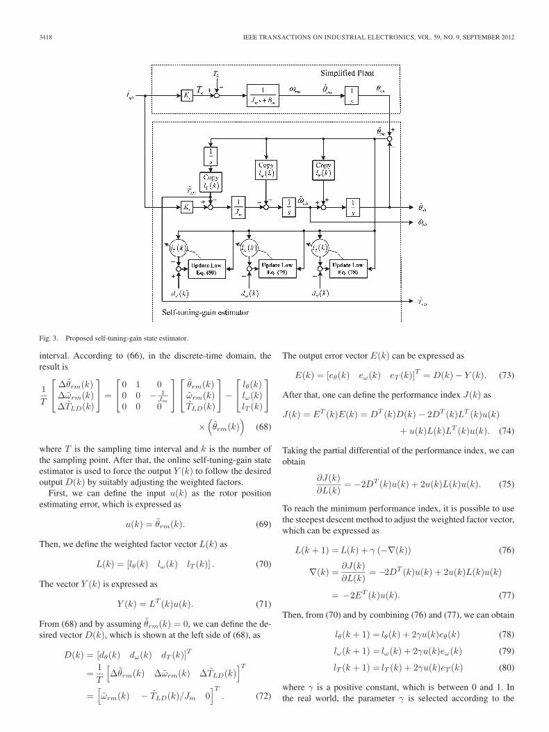
Fig. 3. Proposed self-tuning-gain state estimator.
interval. According to (66), in the discrete-time domain, theresult is
1T
⎡⎣ Δθrm(k)
Δωrm(k)ΔTLD(k)
⎤⎦ =
⎡⎣ 0 1 0
0 0 − 1Jm
0 0 0
⎤⎦
⎡⎣ θrm(k)
ωrm(k)TLD(k)
⎤⎦ −
⎡⎣ lθ(k)
lω(k)lT (k)
⎤⎦
×(θrm(k)
)(68)
where T is the sampling time interval and k is the number ofthe sampling point. After that, the online self-tuning-gain stateestimator is used to force the output Y (k) to follow the desiredoutput D(k) by suitably adjusting the weighted factors.
First, we can define the input u(k) as the rotor positionestimating error, which is expressed as
u(k) = θrm(k). (69)
Then, we define the weighted factor vector L(k) as
L(k) = [lθ(k) lω(k) lT (k)] . (70)
The vector Y (k) is expressed as
Y (k) = LT (k)u(k). (71)
From (68) and by assuming θrm(k) = 0, we can define the de-sired vector D(k), which is shown at the left side of (68), as
D(k) = [dθ(k) dω(k) dT (k)]T
=1T
[Δθrm(k) Δωrm(k) ΔTLD(k)
]T
=[ωrm(k) − TLD(k)/Jm 0
]T
. (72)
The output error vector E(k) can be expressed as
E(k) = [eθ(k) eω(k) eT (k)]T = D(k) − Y (k). (73)
After that, one can define the performance index J(k) as
J(k) = ET (k)E(k) = DT (k)D(k) − 2DT (k)LT (k)u(k)
+ u(k)L(k)LT (k)u(k). (74)
Taking the partial differential of the performance index, we canobtain
∂J(k)∂L(k)
= −2DT (k)u(k) + 2u(k)L(k)u(k). (75)
To reach the minimum performance index, it is possible to usethe steepest descent method to adjust the weighted factor vector,which can be expressed as
L(k + 1) =L(k) + γ (−∇(k)) (76)
∇(k) =∂J(k)∂L(k)
= −2DT (k)u(k) + 2u(k)L(k)u(k)
= −2ET (k)u(k). (77)
Then, from (70) and by combining (76) and (77), we can obtain
lθ(k + 1) = lθ(k) + 2γu(k)eθ(k) (78)
lω(k + 1) = lω(k) + 2γu(k)eω(k) (79)
lT (k + 1) = lT (k) + 2γu(k)eT (k) (80)
where γ is a positive constant, which is between 0 and 1. Inthe real world, the parameter γ is selected according to the
WEI AND LIU: HIGH-PERFORMANCE SENSORLESS POSITION CONTROL SYSTEM OF A SYNRM 3419
Fig. 4. Block diagram of the proposed control system.
designer’s experience. Then, the weighted factors can be onlinetuned.
V. ADAPTIVE POSITION CONTROLLER DESIGN
Only a few papers use advanced controllers in sensorlesscontrol systems because the whole system becomes too com-plicated. As a result, using an adaptive controller to control asensorless reluctance motor controlling system is a big chal-lenge. Adaptive control is an effective technique in dealing withthe parameter uncertainties and the external torque disturbance.In this paper, we propose an adaptive position controller for asensorless SynRM drive system. A detailed description follows.
By combining (8) and (9), we can obtain
Jmθrm = −Bmθrm + iqs − TL. (81)
The normalized parameters Jm, Bm, and TL can be expressedas vector θT
θT =[Jm Bm TL
]=
[Jm
Kt
Bm
Kt
TL
Kt
](82)
where Kt is a torque constant. The position error, which is thedifference between the position command and the real position,can be expressed as
eθ = θ∗rm − θrm. (83)
From (83), we can take the derivation of the position error andthen express its result as
eθ = eω = ω∗rm − ωrm. (84)
In this paper, we select the variable S as
S = K1eθ + eω (85)
where K1 is a positive real value. Then, by combining (81) and(83)–(85), we can obtain
JmS = Jm [K1eω + (ω∗rm − ωrm)]
= −iqs + Jm (K1eω + ω∗rm) + Bmωrm + TL. (86)
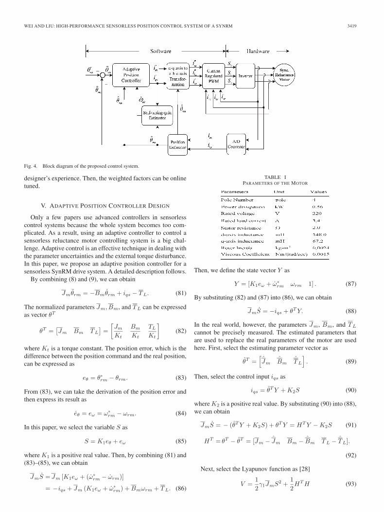
TABLE IPARAMETERS OF THE MOTOR
Then, we define the state vector Y as
Y = [K1eω + ω∗rm ωrm 1] . (87)
By substituting (82) and (87) into (86), we can obtain
JmS = −iqs + θT Y. (88)
In the real world, however, the parameters Jm, Bm, and TL
cannot be precisely measured. The estimated parameters thatare used to replace the real parameters of the motor are usedhere. First, select the estimating parameter vector as
θT =[Jm Bm TL
]. (89)
Then, select the control input iqs as
iqs = θT Y + K2S (90)
where K2 is a positive real value. By substituting (90) into (88),we can obtain
JmS = − (θT Y + K2S) + θT Y = HT Y − K2S (91)
HT = θT − θT = [Jm − Jm Bm − Bm TL − TL].
(92)
Next, select the Lyapunov function as [28]
V =12γ1JmS2 +
12HT H (93)

3420 IEEE TRANSACTIONS ON INDUSTRIAL ELECTRONICS, VOL. 59, NO. 9, SEPTEMBER 2012
Fig. 5. Flowchart of the proposed rotor position estimating technique.
where γ1 is a positive real value. By taking the derivative of(93) and then by combining its result with (91), we can derive
V = γ1S(HT Y − K2S) + HT H
=HT (γ1SY + H) − γ1K2S2. (94)
From (94), we can find the adaption law as
H = −γ1SY. (95)
WEI AND LIU: HIGH-PERFORMANCE SENSORLESS POSITION CONTROL SYSTEM OF A SYNRM 3421
Fig. 6. Trajectories of the current-slope. (a) Traditional method [22].(b) Proposed method.
By substituting (95) into (94), we can obtain
V = −γ1K2S2 ≤ 0. (96)
By integrating (96), we can obtain
∞∫0
S2dτS2 = − 1γ1K2
∞∫0
V dτ =1
γ1K2[V (0) − V (∞)] . (97)
Finally, by applying Barbalet’s Lemma, it is not difficult toobtain [28]
limt→∞
eθ(t) = 0. (98)
According to (96) and (98), by using the proposed controller,the position error of the closed-loop drive system can be asymp-totically converged to zero. As a result, the closed-loop drivesystem is asymptotically stable.
Fig. 7. Measured position responses at 1 r/min. (a) Speed responses.(b) Position responses. (c) Estimated error.
3422 IEEE TRANSACTIONS ON INDUSTRIAL ELECTRONICS, VOL. 59, NO. 9, SEPTEMBER 2012
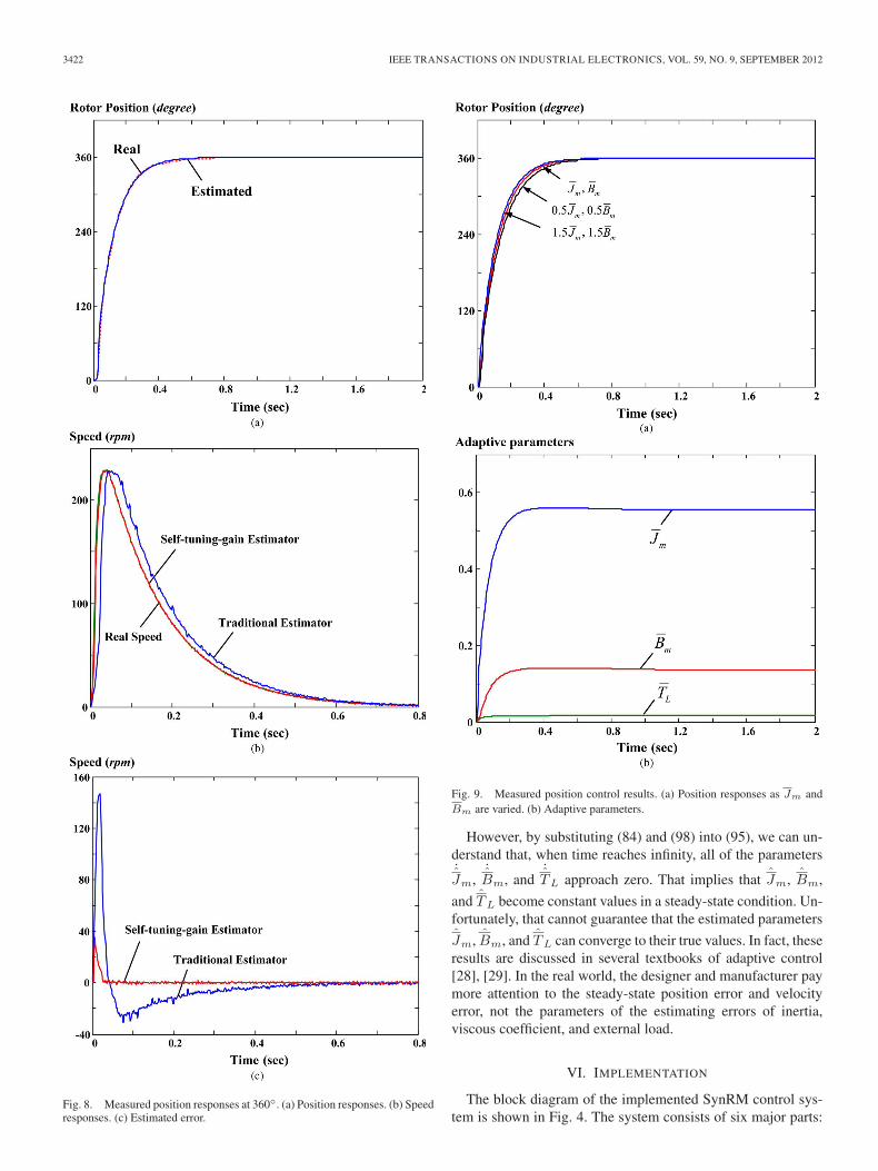
Fig. 8. Measured position responses at 360◦. (a) Position responses. (b) Speedresponses. (c) Estimated error.
Fig. 9. Measured position control results. (a) Position responses as Jm andBm are varied. (b) Adaptive parameters.
However, by substituting (84) and (98) into (95), we can un-derstand that, when time reaches infinity, all of the parameters˙Jm,
˙Bm, and
˙TL approach zero. That implies that Jm, Bm,
and TL become constant values in a steady-state condition. Un-fortunately, that cannot guarantee that the estimated parameters
Jm, Bm, and TL can converge to their true values. In fact, theseresults are discussed in several textbooks of adaptive control[28], [29]. In the real world, the designer and manufacturer paymore attention to the steady-state position error and velocityerror, not the parameters of the estimating errors of inertia,viscous coefficient, and external load.
VI. IMPLEMENTATION
The block diagram of the implemented SynRM control sys-tem is shown in Fig. 4. The system consists of six major parts:

WEI AND LIU: HIGH-PERFORMANCE SENSORLESS POSITION CONTROL SYSTEM OF A SYNRM 3423
Fig. 10. Measured position transient responses.
a DSP, an inverter, a SynRM, a driving circuit, A/D converters,and sensors. A TMS-320F-28335 DSP system was used here.The DSP is different from TMS-320-C30, which was used in[22] and [23]. The DSP provided floating-point operation witha 6.67-ns single-cycle instruction execution time. The DSP wasinterfaced to parallel I/O devices and A/D converters. First, theDSP reads the three-phase currents. Then, the DSP executed therotor estimating algorithm and the control algorithm. Finally,the DSP sent the trigger signals to the inverter. The inverterturned-on or turned-off the six IGBTs, and then, the motorrotated. Most of the jobs were executed by the DSP; thehardware circuit, therefore, was very simple. The inverter was avoltage-source current-regulated type, which was implementedby using six IGBTs. The IGBTs were type PS21265-P/AP,made by Mitsubishi Company. The IGBTs provided a 20-Acontinuous rating current and a 600-V continuous blockingvoltage. The motor was a three-phase, four-pole, and 220-VSynRM, rated 0.75 hp, with 1800-r/min rated speed, manu-factured by Reliance Electric Company. The parameters of themotor are shown in Table I. The d-axis current command wasset at 1 A. The reason is that, when the d-axis current commandwas larger than 1 A, the motor was saturated. On the otherhand, when the d-axis current was smaller than 1 A, the torqueof the motor was very small. By using a hysteresis controller,the current-regulated loop can be achieved. The sensors ofthe system only included the Hall-effect current sensors. Novoltage sensors were required. The Hall-effect sensors weretype LA-25NP, made by the LEM Company. The bandwidthof the Hall-effect sensors was about 150 kHz. The signals ofthe current sensors were sent to the DSP via A/D converters.The A/D converters were 14 bit, with a 2.4-μs conversiontime. The sampling interval of the current and position loopswas 133 μs, and the sampling interval of the velocity loop was1.3 ms.
The flowchart of the interrupt service routine for the rotorposition estimation is shown in Fig. 5. The basic estimating
Fig. 11. Measured load disturbance responses. (a) Position command and realposition. (b) Real and estimated positions.
principle is mentioned in Section III. As you can observe, itis not difficult to estimate the rotor position θre accordingto the dual current-slopes Dias|new_old1, Dibs|new_old1, andDics|new_old2.
VII. EXPERIMENTAL RESULTS
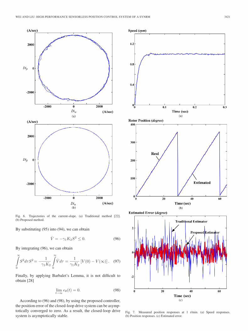
The proposed sensorless algorithm was evaluated by ex-perimental results. The following parameters are selected forthe adaptive controller: K1 = 50, K2 = 10, and γ1 = 0.1.Fig. 6(a) and (b) shows the trajectories of the current-slope ofthe SynRM, which is operated at 400 r/min. Fig. 6(a) showsthe trajectory of a traditional method, which uses the singlecurrent-slope and removes the current-slope by using the zerovoltage switching modes [21]. Fig. 6(b) shows the trajectoryof the proposed method. As you can observe, the performanceusing the proposed estimator can be obviously improved. The

3424 IEEE TRANSACTIONS ON INDUSTRIAL ELECTRONICS, VOL. 59, NO. 9, SEPTEMBER 2012
Fig. 12. Position responses of the proposed technique. (a) Triangular re-sponse. (b) Tracking error.
zero-voltage vector is not used in this paper because a dualcurrent-slope is proposed here. Fig. 7(a)–(c) shows the mea-sured results of the proposed estimating technique. Fig. 7(a)shows the transient responses at 1 r/min. Fig. 7(b) shows thecomparison of the real and estimated rotor positions. The esti-mated rotor position is close to the real rotor position, includingthe standstill, starting, transient, and steady-state conditions.Fig. 7(c) shows the measured estimated error. The proposeddual current-slope method has better performance than thesingle current-slope estimating technique [22].
Fig. 8(a)–(c) shows the responses measured from the pro-posed sensorless SynRM control system. Fig. 8(a) shows theposition transient responses at 360◦. Fig. 8(b) shows the re-sponses of the velocity estimators. As you can see, the onlineself-tuning-gain estimator performs better than the traditionalestimating method [22]. The parameters of the velocity esti-mator are selected as follows: lθ = 20, lω = 30, and lT = 1
Fig. 13. Position responses of the traditional estimating technique. (a) Trian-gular response. (b) Tracking error.
for the traditional estimating method. To design the onlineself-tuning-gain estimator, the weighting factor of the iter-ation is selected as γ = 0.1. Then, the proposed estimatorperforms better than the traditional estimator. Fig. 8(c) showsthe comparison of the measured different speed estimated error.Again, the proposed system performs well. Fig. 9(a) showsthe measured position responses while the parameters Jm andBm are varied from 0.5 to 1.5 times. Although the parametersvaried in a wide range, the transient responses are very close.The proposed drive system, therefore, has good robustness.Fig. 9(b) shows the variation of the adaptive parameters intransient state. Fig. 10 shows the measured position transientresponses at different position commands, which include 1◦,60◦, 120◦, 180◦, 240◦, 300◦, and 360◦. As you can see, theestimated position is quite close to the real position. Again,the system has satisfactory performance. Fig. 11(a) shows theresponses at 200 mechanical degrees with three different loads.

WEI AND LIU: HIGH-PERFORMANCE SENSORLESS POSITION CONTROL SYSTEM OF A SYNRM 3425
Fig. 14. Estimated rotor positions for parameters being varied. (a) Variedresistances (b) Varied inductances.
The proposed drive system, therefore, has good robustness.The relationship between the real and estimated rotor posi-tions is shown in Fig. 11(b). As you can see, the estimatedrotor position is close to the real rotor position, althoughunder a rated load. The rated load of the SynRM is 2 N · m,and the rated current of the motor is 3.4 A.
Fig. 12(a) shows the comparison of the measured triangular-input command and its response to the proposed sensorlesstechnique. As you can observe, the measured position responseis close to the position command. Fig. 12(b) shows the trackingerror, which is around ±0.1◦. Fig. 13(a) and (b) shows themeasured position responses using the traditional single-slopecurrent estimating technique. As you can observe, the trackingerrors are increased to ±0.2◦ when the single current-slopeestimating technique with a zero voltage vector is used tocompensate the back EMF. Figs. 8–12 show that the proposed
method can be applied for a precise position control system.Fig. 14(a) shows the estimated rotor position for varying re-sistances. As you can see, the estimated rotor positions arevery close, although the stator resistances are seriously var-ied. Fig. 14(b) shows the estimated rotor position for varyinginductances. The estimated rotor positions are more seriouslyinfluenced when the inductances are reduced due to saturation.
VIII. CONCLUSION
This paper has presented a novel sensorless technique fora SynRM drive system. By using the dual current-slope andthe self-tuning-gain state estimator, the rotor position of themotor can be accurately estimated. Then, an adaptive controlleris developed to improve the performance of the drive system,which includes transient responses, load disturbance responses,tracking ability, and robustness. Finally, a fully digital, multi-rate, and DSP-based control system is implemented. Severalexperimental results show the feasibility and correctness ofthe proposed method. The proposed method can be applied inindustrial fields due to its simplicity. This paper has presented anew direction for the sensorless SynRM system.
REFERENCES
[1] T. A. Lipo, “Recent progress in the development of solid-state ac mo-tor drives,” IEEE Trans. Power Electron., vol. 3, no. 2, pp. 105–117,Apr. 1988.
[2] B. K. Bose, “Technology trends in microprocessor control of electricalmachines,” IEEE Trans. Ind. Electron., vol. 35, no. 1, pp. 160–177,Feb. 1988.
[3] T. A. Lipo, “Synchronous reluctance machines—A viable alternativefor ac drives,” Elect. Mach. Power Syst., vol. 19, no. 6, pp. 659–671,Nov./Dec. 1991.
[4] R. R. Moghaddam, F. Magnussen, and C. Sadarangani, “Theoretical andexperimental reevaluation of synchronous reluctance machine,” IEEETrans. Ind. Electron., vol. 57, no. 1, pp. 6–13, Jan. 2010.
[5] A. Ghaderi and T. Hanamoto, “Wide-speed-range sensorless vector con-trol of synchronous reluctance motors based on extended programmablecascaded low-pass filters,” IEEE Trans. Ind. Electron., vol. 58, no. 6,pp. 2322–2333, Jun. 2011.
[6] R. M. Caporal and M. Pacas, “Suppression of saturation effects in asensorless predictive controlled synchronous reluctance machine basedon voltage space phasor injections,” IEEE Trans. Ind. Electron., vol. 58,no. 7, pp. 2809–2817, Jul. 2011.
[7] M. Schroedl and P. Weinmeier, “Sensorless control of reluctance machinesat arbitrary operating conditions including standstill,” IEEE Trans. PowerElectron., vol. 9, no. 2, pp. 225–231, Mar. 1994.
[8] P. Guglielmi, M. Pastorelli, and A. Vagati, “Impact of cross-saturationin sensorless control of transverse-laminated synchronous reluctance mo-tors,” IEEE Trans. Ind. Electron., vol. 53, no. 2, pp. 429–439, Apr. 2006.
[9] A. Consoli, C. Cavallaro, G. Scarcella, and A. Testa, “Sensorless torquecontrol of SyncRel motor drives,” IEEE Trans. Power Electron., vol. 15,no. 1, pp. 28–35, Jan. 2000.
[10] H. A. Zarchi, J. Soltani, and G. A. Markadeh, “Adaptive input–outputfeedback-linearization-based torque control of synchronous reluctancemotor without mechanical sensor,” IEEE Trans. Ind. Electron., vol. 57,no. 1, pp. 375–384, Jan. 2010.
[11] S. Ichikawa, M. Tomita, S. Doki, and S. Okuma, “Sensorless controlof synchronous reluctance motors based on extended EMF models con-sidering magnetic saturation with online parameter identification,” IEEETrans. Ind. Appl., vol. 42, no. 5, pp. 1264–1274, Sep./Oct. 2006.
[12] E. Capecchi, P. Guglielmi, M. Pastrorelli, and A. Vagati, “Position-sensorless control of the transverse-laminated synchronous reluctancemotor,” IEEE Trans. Ind. Appl., vol. 37, no. 6, pp. 1768–1776,Nov./Dec. 2001.
[13] R. M. Caporal and M. Pacas, “Encoderless predictive direct torque controlfor synchronous reluctance machines at very low and zero speed,” IEEETrans. Ind. Electron., vol. 55, no. 12, pp. 4408–4416, Dec. 2008.

3426 IEEE TRANSACTIONS ON INDUSTRIAL ELECTRONICS, VOL. 59, NO. 9, SEPTEMBER 2012
[14] G. Foo and M. F. Rahman, “Sensorless direct torque and flux-controlledIPM synchronous motor drive at very low speed without signal injection,”IEEE Trans. Ind. Electron., vol. 57, no. 1, pp. 395–403, Jan. 2010.
[15] J. I. Ha, S. J. Kang, and S. K. Sul, “Position-controlled synchronousreluctance motor without rotational transducer,” IEEE Trans. Ind. Appl.,vol. 35, no. 6, pp. 1393–1398, Nov./Dec. 1999.
[16] S. J. Kang, J. M. Kim, and S. K. Sul, “Position sensorless control ofsynchronous reluctance motor using high frequency current injection,”IEEE Trans. Energy Convers., vol. 14, no. 4, pp. 1271–1275, Dec. 1999.
[17] A. Consoli, F. Russo, G. Scarcella, and A. Testa, “Low- and zero-speedsensorless control of synchronous reluctance motors,” IEEE Trans. Ind.Appl., vol. 35, no. 5, pp. 1050–1057, Sep./Oct. 1999.
[18] H. W. D. Kock, M. J. Kamper, and R. M. Kennel, “Anisotropy compari-son of reluctance and PM synchronous machines for position sensorlesscontrol using HF carrier injection,” IEEE Trans. Power Electron., vol. 24,no. 8, pp. 1905–1913, Aug. 2009.
[19] A. Consoli, G. Scarcella, G. Scelba, A. Testa, and D. A. Triolo, “Selsorlessrotor position estimation in synchronous reluctance motors exploiting aflux deviation approach,” IEEE Trans. Ind. Appl., vol. 43, no. 5, pp. 1266–1273, Sep./Oct. 2007.
[20] T. Matsuo and T. A. Lipo, “Rotor position detection scheme for synchro-nous reluctance motor based on current measurements,” IEEE Trans. Ind.Appl., vol. 31, no. 4, pp. 860–868, Jul./Aug. 1995.
[21] M. F. Rahman, N. C. Cheung, and K. W. Lim, “Position estimation insolenoid actuators,” IEEE Trans. Ind. Appl., vol. 32, no. 3, pp. 552–559,May/Jun. 1996.
[22] C. G. Chen, T. H. Liu, M. T. Lin, and C. A. Tai, “Position control ofa sensorless synchronous reluctance motor,” IEEE Trans. Ind. Electron.,vol. 51, no. 1, pp. 15–25, Feb. 2004.
[23] M. T. Lin and T. H. Liu, “Sensorless synchronous reluctance drive withstandstill starting,” IEEE Trans. Aerosp. Electron. Syst., vol. 36, no. 4,pp. 1232–1241, Oct. 2000.
[24] M. A. Vogelsberger, S. Grubic, T. G. Habetler, and T. M. Wolbank, “UsingPWM-induced transient excitation and advanced signal processing forzero-speed sensorless control of ac machines,” IEEE Trans. Ind. Electron.,vol. 57, no. 1, pp. 365–374, Jan. 2010.
[25] F. M. L. De Belie, P. Sergeant, and J. A. Melkebeek, “A sensorless driveby applying test pulses without affecting the average-current samples,”IEEE Trans. Power Electron., vol. 25, no. 4, pp. 875–888, Apr. 2010.
[26] E. S. Obe, “Calculation of inductances and torque of an axially laminatedsynchronous reluctance motor,” IET Elect. Power Appl., vol. 4, no. 9,pp. 783–792, Nov. 2010.
[27] C. T. Chen, Linear System Theory and Design. New York: Oxford Univ.Press, 1999.
[28] G. Tao, Adaptive Control Design and Analysis. Hoboken, NJ: Wiley-Interscience, 2003.
[29] K. J. Astrom and B. Wittenmark, Adaptive Control. Reading, MA:Addison-Wesley, 1995.
Ming-Yen Wei was born in Taichung, Taiwan, onApril 20, 1983. He received the B.S. and M.S.degrees in electrical engineering from NationalFormosa University, Yunlin, Taiwan, in 2005 and2007, respectively. He is currently working towardthe Ph.D. degree in electrical engineering at the Na-tional Taiwan University of Science and Technology,Taipei, Taiwan.
His research interests include sensorless tech-niques, applications of control theory, and DSP-based digital control system design.
Tian-Hua Liu (S’85–M’89–SM’99) was born in TaoYuan, Taiwan, on November 26, 1953. He receivedthe B.S., M.S., and Ph.D. degrees in electrical en-gineering from the National Taiwan University ofScience and Technology, Taipei, Taiwan, in 1980,1982, and 1989, respectively.
From August 1984 to July 1989, he was an In-structor with the Department of Electrical Engi-neering, National Taiwan University of Science andTechnology. He was a Visiting Scholar with theWisconsin Electric Machines and Power Electronics
Consortium, University of Wisconsin, Madison, from September 1990 toAugust 1991 and with the Center of Power Electronics Systems, Virginia Poly-technic Institute and State University, Blacksburg, from July 1999 to January2000. From August 1989 to January 1996, he was an Associate Professorwith the Department of Electrical Engineering, National Taiwan University ofScience and Technology, where he served as Department Chair from 2007 to2009 and where he has been a Professor since February 1996. His researchinterests include motor controls, power electronics, and microprocessor-basedcontrol systems.
Related Documents