Research Library Research Library Bulletins 4000 - Research Publications 1990 A guide to barbed wire fence construction for range cattle control A guide to barbed wire fence construction for range cattle control J S. Addison Follow this and additional works at: https://researchlibrary.agric.wa.gov.au/bulletins Part of the Bioresource and Agricultural Engineering Commons Recommended Citation Recommended Citation Addison, J S. (1990), A guide to barbed wire fence construction for range cattle control. Department of Primary Industries and Regional Development, Western Australia, Perth. Bulletin 4183. This bulletin is brought to you for free and open access by the Research Publications at Research Library. It has been accepted for inclusion in Bulletins 4000 - by an authorized administrator of Research Library. For more information, please contact [email protected].

Welcome message from author
This document is posted to help you gain knowledge. Please leave a comment to let me know what you think about it! Share it to your friends and learn new things together.
Transcript
Research Library Research Library
Bulletins 4000 - Research Publications
1990
A guide to barbed wire fence construction for range cattle control A guide to barbed wire fence construction for range cattle control
J S. Addison
Follow this and additional works at: https://researchlibrary.agric.wa.gov.au/bulletins
Part of the Bioresource and Agricultural Engineering Commons
Recommended Citation Recommended Citation Addison, J S. (1990), A guide to barbed wire fence construction for range cattle control. Department of
Primary Industries and Regional Development, Western Australia, Perth. Bulletin 4183.
This bulletin is brought to you for free and open access by the Research Publications at Research Library. It has been accepted for inclusion in Bulletins 4000 - by an authorized administrator of Research Library. For more information, please contact [email protected].
© Chief Executive Officer, Department of Agriculture, Western Australia 1990
By Jim Addison, Technical Officer, Department of Agriculture, Derby
cattle control construction for range to barbed wire fence
guide A
Department of Agriculture - Western Australia
July 1990
• Bulletin No. 4183
Agdex 723 ISSN 0729-0012
3 ••••••••••••
Introduction 4 Fenceline pegging 4
• Checking the line 4 • Placement of sighters 5
Line clearing 5 Strainer assemblies 5
• Materials 5 • Type of assembly 5 • Post depth 6 • Strut length 6 • Concrete versus rammed dirt 6 •Whereto tie the in-line wires 6 • Strut alignment 6 • A prefabricated steel end assembly 7 • Strainer assemblies at fenceline corners 8 • The continuous strainer-to-strainer method 9
The wire 9 • Trailed barbed wire jenny 10 • Tying off in-line wire to a strainer assembly 11 • Wire strainer tension meters 11 • Tension loss in high tensile barbed wire fencing 11
Tie wire 11 Line posts 11
• Tying in-line wire to a steel picket 12 • Positioning of line posts 12
Fence droppers 12 Preventative maintenance 12 Appendix A: Typical wire spacings for cattle control 13 Appendix B: Freight weights 14 Appendix C: Construction hints 14 Appendix D: Further reading 14
Contents
By Jim Addison, Technical Officer, Derby
range cattle control fence construction for A guide to barbed wire
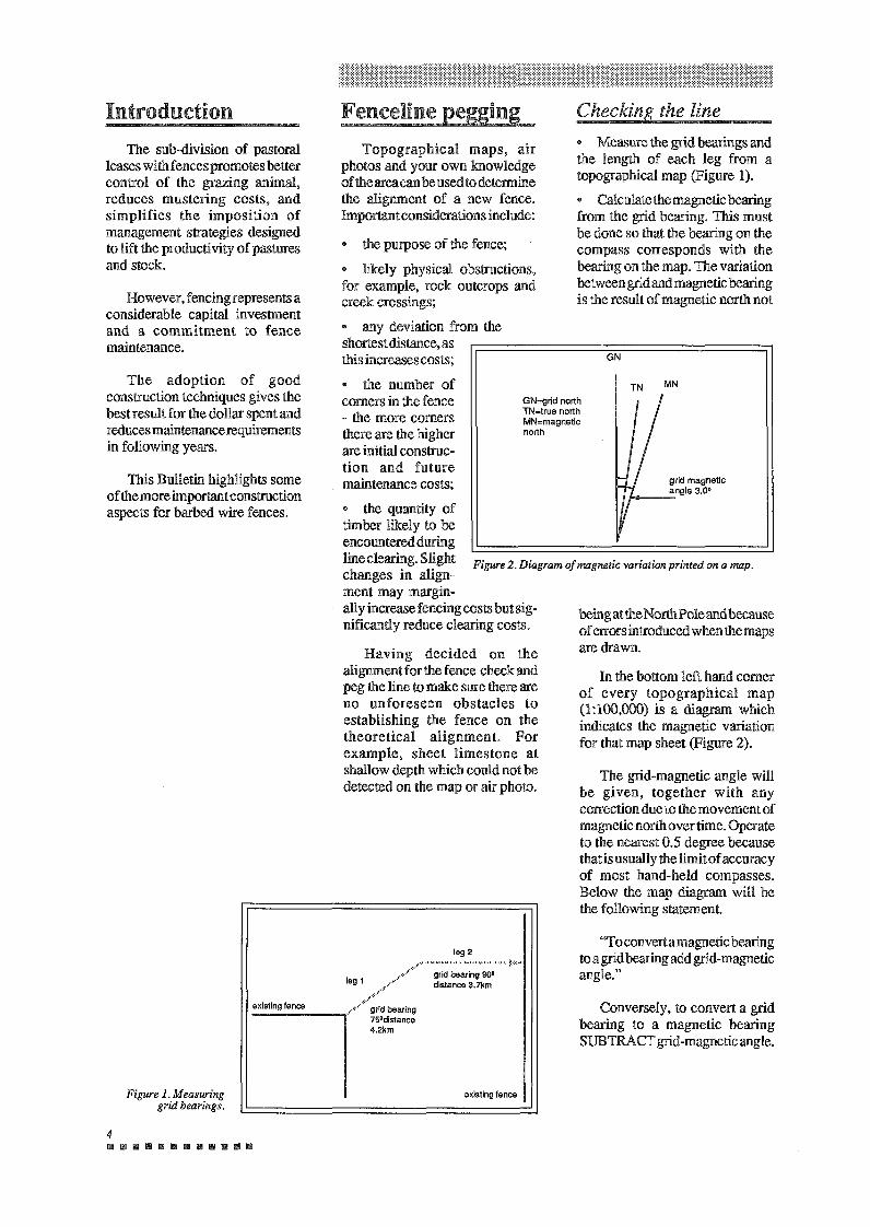
Conversely, to convert a grid bearing to a magnetic bearing SUBTRACT grid-magnetic angle.
"To convert a magnetic bearing to a grid bearing add grid-magnetic angle."
The grid-magnetic angle will be given, together with any correction due to the movement of magnetic north overtime. Operate to the nearest 0.5 degree because that is usually the limit of accuracy of most hand-held compasses. Below the map diagram will be the following statement.
In the bottom left hand comer of every topographical map (1:100,000) is a diagram which indicates the magnetic variation for that map sheet (Figure 2).
being attheNorthPoleand because of errors introduced when the maps are drawn.
4 11111111111111111111111111111111111
existing fence
grid bearing 900 distance 3. 7km
,,······························'·'''·'·'•'·'·'·'·'·'·'·'·'·-:·:·:··· ,,•' ... , .. :· leg 1
leg 2
_.... •. /····;;;: bearing -------. 75°distance
4.2km
existing fence
Figure 1. Measuring grid bearings.
Having decided on the alignment for the fence check and peg the line to make sure there are no unforeseen obstacles to establishing the fence on the theoretical alignment. For example, sheet limestone at shallow depth which could not be detected on the map or air photo.
Figure 2. Diagram of magnetic variation printed on a map.
grid magnetic angle 3.0° ,_ __
MN TN
GN
the quantity of timber likely to be encountered during line clearing. Slight changes in align ment may margin- ally increase fencing costs but sig nificantly reduce clearing costs.
GN=grid north TN=true north MN=magnetlc north
Measure the grid bearings and the length of each leg from a topographical map (Figure 1).
Calculate the magnetic bearing from the grid bearing. This must be done so that the bearing on the compass corresponds with the bearing on the map. The variation between grid and magnetic bearing is the result of magnetic north not
Checking the line
the purpose of the fence;
likely physical obstructions, for example, rock outcrops and creek crossings;
any deviation from the shortest distance, as this increases costs;
the number of comers in the fence - the more comers there are the higher are initial construc- tion and future maintenance costs;
Topographical maps, air photos and your own knowledge oftheareacanbeusedtodetermine the alignment of a new fence. Important considerations include:
Fenceline pegging
This Bulletin highlights some of the more important construction aspects for barbed wire fences.
The adoption of good construction techniques gives the best result for the dollar spent and reduces maintenance requirements in following years.
However, fencing represents a considerable capital investment and a commitment to fence maintenance.
The sub-division of pastoral leases with fences promotes better control of the grazing animal, reduces mustering costs, and simplifies the imposition of management strategies designed to lift the productivity of pastures and stock.
Introduction
5 11!11111!1111111111111111111111111
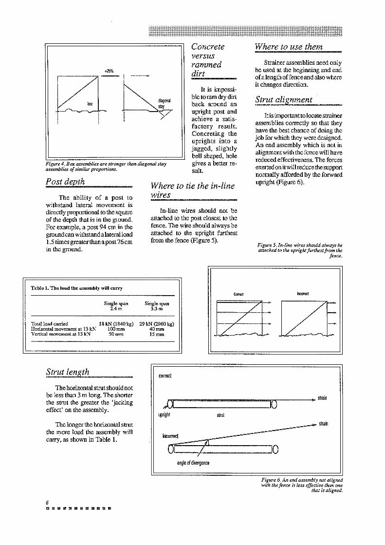
Boxassembliesare25percent stronger than diagonal stay assemblies of similar proportion (Figure4).
TyPe of assembly
Experience in the Kimberley indicates that steel is the only material worth using ( except in some saline conditions). It simplifies construction to the correct geometry and it has strength and durability.
Materials
The following points are important when constructing strainer assemblies.
Strainer assemblies
Afenceline thatis badly eroded becomes less effective as a barrier to stock (because the distance between the ground and bottom wire may become too great) and is far more difficult to maintain.
It is inconvenient to have to cut the in-line wire, move the vehicle to the other side of the creek, and pull out and rejoin the wire. However, it is not as inconvenient as having to pull the fence out of the bottom of a gully within five years.
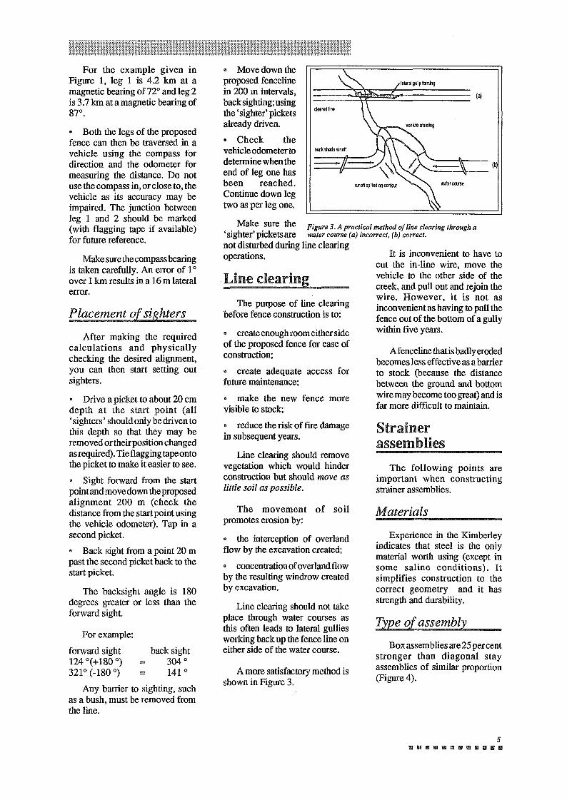
A more satisfactory method is shown in Figure 3.
The movement of soil promotes erosion by:
• the interception of overland flow by the excavation created;
• concentration of overland flow by the resulting windrow created by excavation.
Line clearing should not take place through water courses as this often leads to lateral gullies working back up the fence line on either side of the water course.
• create enough room either side of the proposed fence for ease of construction;
• create adequate access for future maintenance;
• make the new fence more visible to stock;
• reduce the risk of fire damage in subsequent years.
Line clearing should remove vegetation which would hinder construction but should move as little soil as possible.
The purpose of line clearing before fence construction is to:
Line clearing.
Make sure the F' 3 A . 1 . . , , , . tgure . practica method of [me clearing through a sighter pickets are watercourse (a) incorrect, (b) correct.
not disturbed during line clearing operations.
• Move down the proposed fenceline in 200 m intervals, back sighting; using the 'sighter' pickets already driven. • Check the vehicle odometer to determine when the end of leg one has been reached. Continue down leg two as per leg one.
Any barrier to sighting, such as a bush, must be removed from the line.
back sight = 304° = 141 °
For example:
forward sight 124 °(+180 °) 321 ° (-180 °)
The backsight angle is 180 degrees greater or less than the forward sight.
• Drive a picket to about 20 cm depth at the start point (all 'sighters' should only be driven to this depth so that they may be removed or their position changed asrequired). Tieflaggingtapeonto the picket to make it easier to see.
Sight forward from the start point and move down the proposed alignment 200 m (check the distance from the start point using the vehicle odometer). Tap in a second picket.
Back sight from a point 20 m past the second picket back to the start picket.
After making the required calculations and physically checking the desired alignment, you can then start setting out sighters.
Placement of sighters
Make sure the compass bearing is taken carefully. An error of 1 ° over 1 km results in a 16 m lateral error.
• Both the legs of the proposed fence can then be traversed in a vehicle using the compass for direction and the odometer for measuring the distance. Do not use the compass in, or close to, the vehicle as its accuracy may be impaired. The junction between leg I and 2 should be marked (with flagging tape if available) for future reference.
For the example given in Figure 1, leg 1 is 4.2 km at a magnetic bearing of 72° and leg 2 is 3.7 km at a magnetic bearing of g70,
......... · ····· :····· .··.···I\':)'?'?tt?t?tltt?llt)l@l ,.:.:.:.,.'.:.:.: :.: :.: .. :.: .. :.·.:.:.: : .
6 IIIIIIIBIIIIIIIIIIIIIIIB
Figure 6. An end assembly not aligned with the fence is less effective than one
that is aligned.
The longer the horizontal strut the more load the assembly will carry, as shown in Table 1.
)J 10 • strain
upright strut -- strain
Incorrect
Oi 7 21 10 7 angle of divergence
The horizontal strut should not be less than 3 m long. The shorter the strut the greater the 'jacking effect' on the assembly.
correct Strut length
To1'!1 load carried 18 kN (1840 kg) 29 kN (2960 kg) Honzontal movement at 13 kN 100 mm 40 mm Vertical movement at 13 kN 50 mm 15 mm
Single span 3.3 m
Single span 2.4m
Correct Incorrect Table 1. The load the assembly will carry
Figure 5. In-line wires should always be attached to the upright furthest from the
fence.
In-line wires should not be attached to the post closest to the fence. The wire should always be attached to the upright furthest from the fence (Figure 5).
The ability of a post to withstand lateral movement is directly proportional to the square of the depth that is in the ground. For example, a post 94 cm in the ground can withstandalateralload 1.5 times greater than a post 76 cm in the ground.
Where to tie the in-line wires
Post depth
Figure 4. Box assemblies are stronger than diagonal stay assemblies of similar proportions.
Itis importantto locate strainer assemblies correctly so that they have the best chance of doing the job for which they were designed. An end assembly which is not in alignment with the fence will have reduced effectiveness. The forces exerted on it will reduce the support normally afforded by the forward upright (Figure 6).
Strut alignment It is impossi
ble to ram dry dirt back around an upright post and achieve a satis factory result. Concreting the uprights into a jagged, slightly bell shaped, hole gives a better re sult
+25% Strainer assemblies need only
be used at the beginning and end of a length of fence and also where it changes direction.
Where to use them Concrete versus rammed dirt
7 ............. Sequence of construction:
In the workshop, measure, cut and weld steel as per diagram
Railway iron or bore casing may be substituted for the black pipe in the construction of uprights.
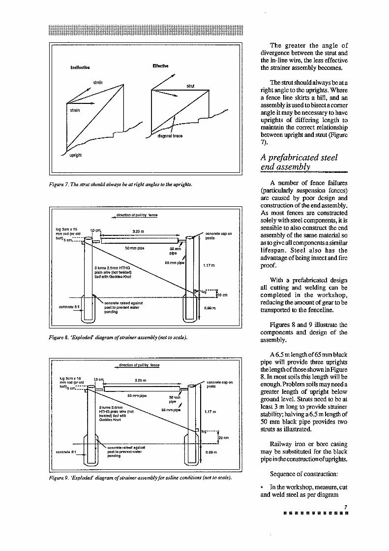
A 6.5 m length of 65 mm black pipe will provide three uprights the length of those shown in Figure 8. In most soils this length will be enough. Problem soils may need a greater length of upright below ground level. Struts need to be at least 3 m long to provide strainer stability; halving a 6.5 m length of 50 mm black pipe provides two struts as illustrated.
Figures 8 and 9 illustrate the components and design of the assembly.
With a prefabricated design all cutting and welding can be completed in the workshop, reducing the amount of gear to be transported to the fenceline.
A number of fence failures (particularly suspension fences) are caused by poor design and construction of the end assembly. As most fences are constructed solely with steel components, it is sensible to also construct the end assembly of the same material so as to give all components a similar lifespan. Steel also has the advantage of being insect and fire proof.
The strut should always be at a right angle to the uprights. Where a fence line skirts a hill, and an assembly is used to bisect a corner angle it may be necessary to have uprights of differing length to maintain the correct relationship between upright and strut (Figure 7).
A prefabricated steel end assembly
The greater the angle of divergence between the strut and the in-line wire, the less effective the strainer assembly becomes.
Figure 9. 'Exploded' diagram of strainer assembly for saline conditions (not to scale).
o.99m concrete 5:1 concrete raised against post to prevent water ponding
lug···]- 20em
~-~~-----~~---~~--11-+--H~·
1.17m
l 3Bmm pipe I
65mmplpe
concrete cap on posts
lug3emx15 mm rod (or old bolt)50rn:::::·
, direction of pull by fence
Figure 8. 'Exploded' diagram of strainer assembly (not to scale).
o.99m concrete 5:1 concrete raised against post to prevent water ponding
1.17m
concrete cap on posts
• direction of pull by fence
Figure 7. The strut should always be at right angles to the uprights.
strain
Effective Ineffective
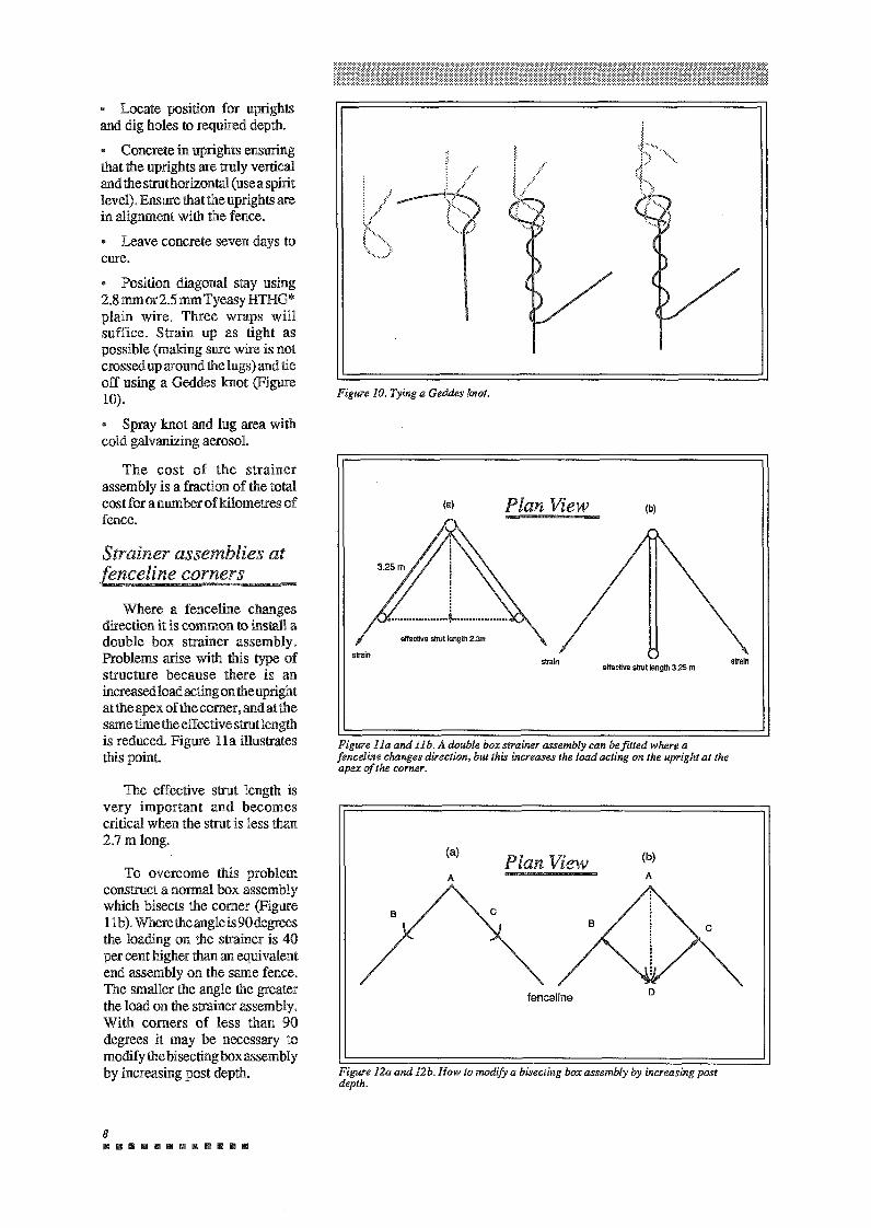
Figure 12a and 12b. How to modify a bisecting box assembly by increasing post depth.
fenceline
(b) A
Plan View A
(a)
Figure l la and 11 b. A double box strainer assembly can be fitted where a fenceline changes direction, but this increases the load acting on the upright at the apex of the corner.
slrain effective strut lenglh 3.25 m strain
(b)
strain
effective strut lenglh 2.3m
Plan View (a)
Figure 10. Tying a Geddes knot.
8 IIIIIIIIIIIIIIIIIIIIIElllllllll!IIII
To overcome this problem construct a normal box assembly which bisects the comer (Figure 11 b). Where the angle is 90 degrees the loading on the strainer is 40 per cent higher than an equivalent end assembly on the same fence. The smaller the angle the greater the load on the strainer assembly. With corners of less than 90 degrees it may be necessary to modify the bisecting box assembly by increasing post depth.
The effective strut length is very important and becomes critical when the strut is less than 2.7 m long.
Where a fenceline changes direction it is common to install a double box strainer assembly. Problems arise with this type of structure because there is an increased load acting on the upright at the apex of the comer, and at the same time the effective strut length is reduced. Figure lla illustrates this point.
Strainer assemblies at fenceline corners
Position diagonal stay using 2.8 mmor2.5 mm Tyeasy HTHG* plain wire. Three wraps will suffice. Strain up as tight as possible (making sure wire is not crossed up around the lugs) and tie off using a Geddes knot (Figure 10).
Spray knot and lug area with cold galvanizing aerosol.
The cost of the strainer assembly is a fraction of the total cost for a num her of kilometres of fence.
Locate position for uprights and dig holes to required depth.
Concrete in uprights ensuring that the uprights are truly vertical and the strut horizontal ( use a spirit level). Ensure that the uprights are in alignment with the fence.
Leave concrete seven days to cure.
9 B II B II· II II II 18 II II II II
1.3 kN (136 kg) 1.3 kN (136 kg) 1.3 kN (136 kg)
45 24 28
2.5 mm Iowa 400 1.57 mm HT 500 1.8mmHT 500
Recommended tension
Wire Length per reel (m)
Approx weight per reel (kg)
High tensile barbed wire is available in two sizes, 1.57 mm diameter and 1.8 mm diameter. The 1.57 mm high tensile wire has
Iowa barbed wire is made from 2.5 mm diameter soft wire in a continuous twist pattern with barb spacings at 100 mm intervals. It is available with either standard or heavy galvanized coating.
There are two types of barbed wire available: Iowa pattern and High Tensile.
The wire
Once all the wire has been pulled up to the required tension, it can be tied onto the posts and the droppers fixed to the wire.
Simply run out the in-line wire from strainer to strainer, pulling up the slack at each join in the process. At the far strainer pull the fence up to the required tension. Then go back to each join and the first strainer, pulling up again to required tension. Surveyors tape tied at the joins ensures easy relocation.
The continuous strainer-to-strainer method
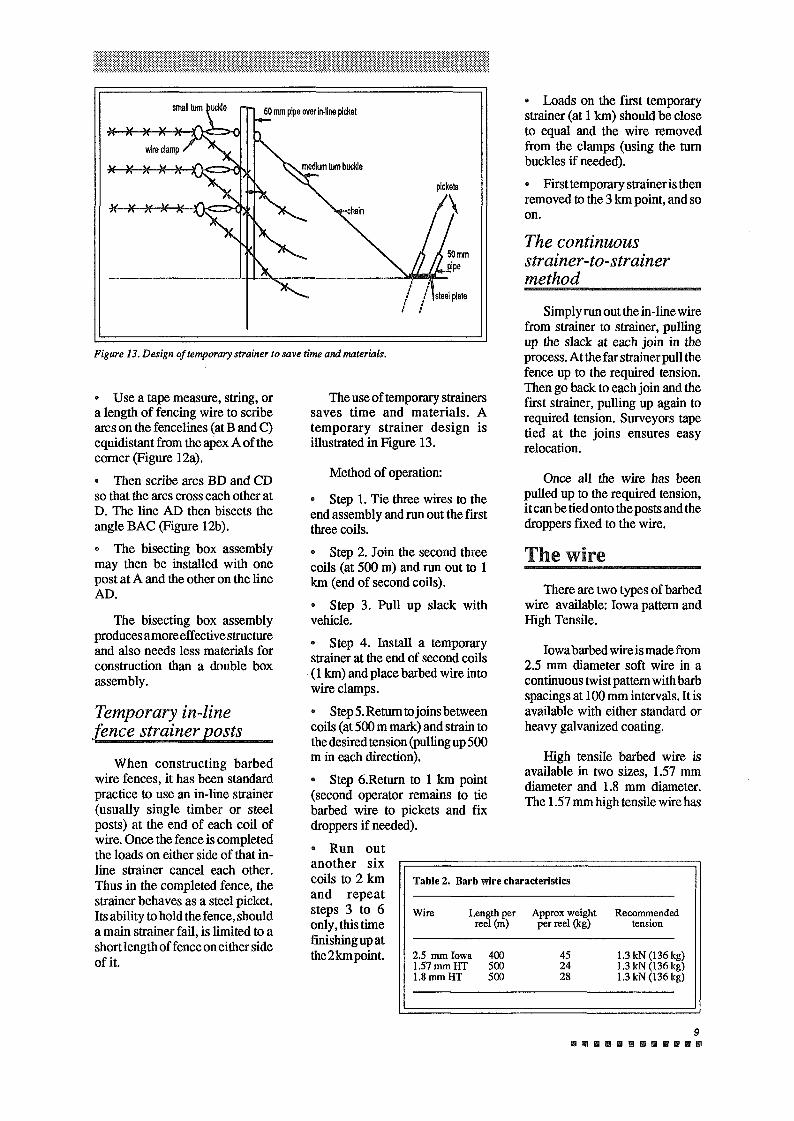
• Loads on the first temporary strainer (at 1 km) should be close to equal and the wire removed from the clamps (using the turn buckles if needed).
• First temporary strainer is then removed to the 3 km point, and so on.
Method of operation:
Step 1. Tie three wires to the end assembly and run out the first three coils.
Step 2. Join the second three coils (at 500 m) and run out to 1 km (end of second coils).
Step 3. Pull up slack with vehicle.
Step 4. Install a temporary strainer at the end of second coils (1 km) and place barbed wire into wire clamps.
• Step 5. Return to joins between coils (at 500 m mark) and strain to the desired tension (pulling up 500 m in each direction).
Step 6.Return to 1 km point (second operator remains to tie barbed wire to pickets and fix droppers if needed).
• Run out another six coils to 2 km and repeat steps 3 to 6 only, this time finishing up at the2kmpoint.
The use of temporary strainers saves time and materials. A temporary strainer design is illustrated in Figure 13.
Table 2. Barb wire characteristics
When constructing barbed wire fences, it has been standard practice to use an in-line strainer (usually single timber or steel posts) at the end of each coil of wire. Once the fence is completed the loads on either side of that in line strainer cancel each other. Thus in the completed fence, the strainer behaves as a steel picket. Its ability to hold the fence, should a main strainer fail, is limited to a short length of fence on either side of it.
Temporary in-line fence strainer posts
The bisecting box assembly produces amoreeffective structure and also needs less materials for construction than a double box assembly.
• Use a tape measure, string, or a length of fencing wire to scribe arcs on the fencelines (at B and C) equidistant from the apex A of the corner (Figure 12a).
Then scribe arcs BD and CD so that the arcs cross each other at D. The line AD then bisects the angle BAC (Figure 12b).
The bisecting box assembly may then be installed with one post at A and the other on the line AD.
Figure 13. Design of temporary strainer to save time and materials.
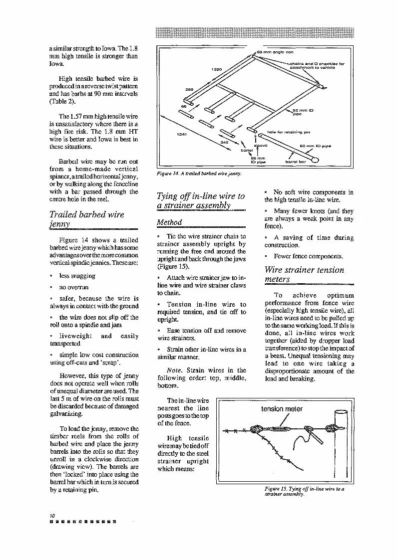
Figure 15. Tying off in-line wire to a strainer assembly.
tension meter
I High tensile
wiremaybetiedoff directly to the steel strainer upright which means:
To achieve optimum performance from fence wire (especially high tensile wire), all in-line wires need to be pulled up to the same working load. If this is done, all in-line wires work together (aided by dropper load transference) to stop the impact of a beast. Unequal tensioning may lead to one wire taking a disproportionate amount of the load and breaking.
Wire strainer tension meters
• No soft wire components in the high tensile in-line wire.
• Many fewer knots (and they are always a weak point in any fence).
• A saving of time during construction. • Fewer fence components.
The in-line wire nearest the line posts goes to the top of the fence.
Note. Strain wires in the following order: top, middle, bottom.
• Tie the wire strainer chain to strainer assembly upright by running the free end around the upright and back through the jaws (Figure 15).
• Attach wire strainer jaw to in line wire and wire strainer claws to chain.
• Tension in-line wire to required tension, and tie off to upright. • Ease tension off and remove wire strainers.
• Strain other in-line wires in a similar manner.
Method
Tying off in-line wire to a strainer assembly
Figure 14. A trailed barbed wire jenny.
10 B B B B II II Ill 8 B B B Ii
To load the jenny, remove the timber reels from the rolls of barbed wire and place the jenny barrels into the rolls so that they unroll in a clockwise direction (drawing view). The barrels are then 'locked' into place using the barrel bar which in tum is secured by a retaining pin.
safer, because the wire is always in contact with the ground
• the wire does not slip off the roll onto a spindle and jam • liveweight and easily transported
simple low cost construction using off-cuts and 'scrap'.
However, this type of jenny does not operate well when rolls of unequal diameter are used. The last 5 m of wire on the rolls must be discarded because of damaged galvanizing.
• no overrun
Figure 14 shows a trailed barbed wire jenny which has some advantagesoverthemorecommon vertical spindle jennies. These are:
• less snagging
Trailed barbed wire .1enny
Barbed wire may be run out from a home-made vertical spinner, a trailed horizontal jenny, or by walking along the fenceline with a bar passed through the centre hole in the reel.
The 1.57 mm high tensile wire is unsatisfactory where there is a high fire risk. The 1.8 mm HT wire is better and Iowa is best in these situations.
High tensile barbed wire is produced in areverse twist pattern and has barbs at 90 mm intervals (Table 2).
a similar strength to Iowa. The 1.8 mm high tensile is stronger than Iowa.
11 ••••••••••••
In-line wire is held off steel posts by the use of tie wire, to prevent corrosion. Corrosion is caused where electrolysis takes place between the steel of the post and the in-line wire.
Tying in-line wire to a steel picket
support and space the in-line wire component.
• give the fence resistance to overturning.
The two materials commonly used for line posts are steel and termite resistant timber (used mainly in saline situations).
The functions of line posts are to:
Line posts
Forty centimetres of tie wire is enough to attach the in-line wire to a steel picket.
Soft wire, 2.5 mm diameter, is adequate for most tying. Wire of smaller diameter is not strong enough for general application.
Tie wire
Hot fires may affect the elasticity characteristics of the wire and even cause breakage. Fence lines needs protection from fire to maintain peak performance from high tensile fence wire.
Long strains result in lower tension losses.
The straighter the fence line between strainers and the fewer the number of in-line posts, the lower the risk of tension loss.
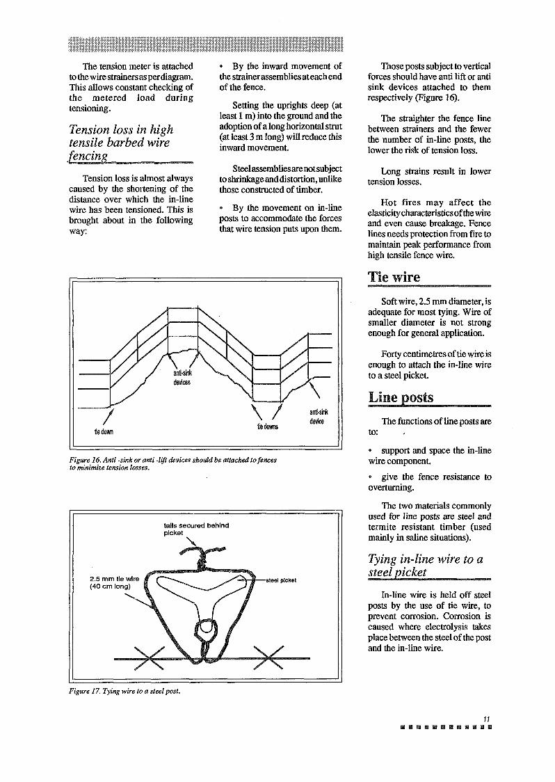
Those posts subject to vertical forces should have anti lift or anti sink devices attached to them respectively (Figure 16).
Figure 17. Tying wire to a steel post.
tails secured behind picket
"
Figure 16. Anti -sink or anti -lift devices should be attached to fences to minimize tension losses.
tie down tie downs anti-silk device I
• By the movement on in-line posts to accommodate the forces that wire tension puts upon them.
Tension loss is almost always caused by the shortening of the distance over which the in-line wire has been tensioned. This is brought about in the following way:
Steel assemblies are not subject to shrinkage and distortion, unlike those constructed of timber.
Tension loss in high tensile barbed wire fencins
Setting the uprights deep (at least 1 m) into the ground and the adoption of a long horizontal strut (at least 3 m long) will reduce this inward movement.
• By the inward movement of the strainer assemblies at each end of the fence.
The tension meter is attached to the wire strainers as per diagram. This allows constant checking of the metered load during tensioning.
The fence must be visible to domestic stock and feral animals. This will result in fewer animal impacts on the fence and consequently lower maintenance requirements.
Visibility to grazing animals
Access to fence line must be maintained to allow for wire maintenance operations.
Fence access
radically alter the characteristics offence wire. In severe cases, the wire may fail totally.
Firebreaks will protect the fence from fire and allow woody weeds to be controlled within and near the fenceline. Hot fires
Protection from fire
A high standard of construction will reduce maintenance requirements.
High quality fence components should suit the environment, for example, don't use steel pickets in highly saline conditions.
A fence should be aligned to minimize the number of potential trouble spots such as creeks.
Initial construction
Preventative maintenance consists of attention to:
Preventative maintenance
• topography,
• animal pressure,
• wire tension.
There is no hard and fast rule as to the best spacing of droppers. Each length of fence will have to be assessed on its own merit. Considerations will include:
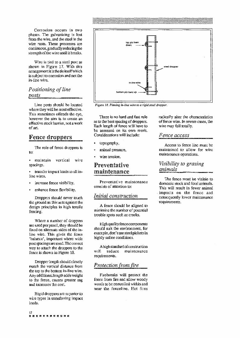
Figure 18. Pinning in-line wire to a rigid steel dropper.
steel dropper
12 II Ill Ill Ill Ill Ill 111 11 lill 111111 lill
Rigid droppers are superior to wire types in transferring impact loads.
Dropper length should closely match the vertical distance from the top to the bottom in-line wire. Any additional length adds weight to the fence, causes greater sag and increases the cost.
Where a number of droppers are used per panel, they should be fixed on alternate sides of the in line wire. This gives the fence 'balance', important where wide post spacings are used. The correct way to attach the droppers to the fence is shown in Figure 18.
• maintain vertical wire spacings. • transfer impact loads to all in line wires. • increase fence visibility.
enhance fence flexibility.
Droppers should never touch the ground as this acts against the design principles in high tensile fencing.
The role of fence droppers is to:
Fence dropp~rs
Line posts should be located where they will be most effective. This sometimes offends the eye, however the aim is to create an effective stock barrier, not a work of art.
Positioning of line posts
Wire is tied to a steel post as shown in Figure 17. With this arrangement it is the tie itself which is subject to corrosion and not the in- line wire.
Corrosion occurs in two phases. The galvanizing is lost from the wire, and the steel in the wire rusts. These processes are continuous, gradually reducing the strength of the wire until it breaks.
13 111111111111111111111111
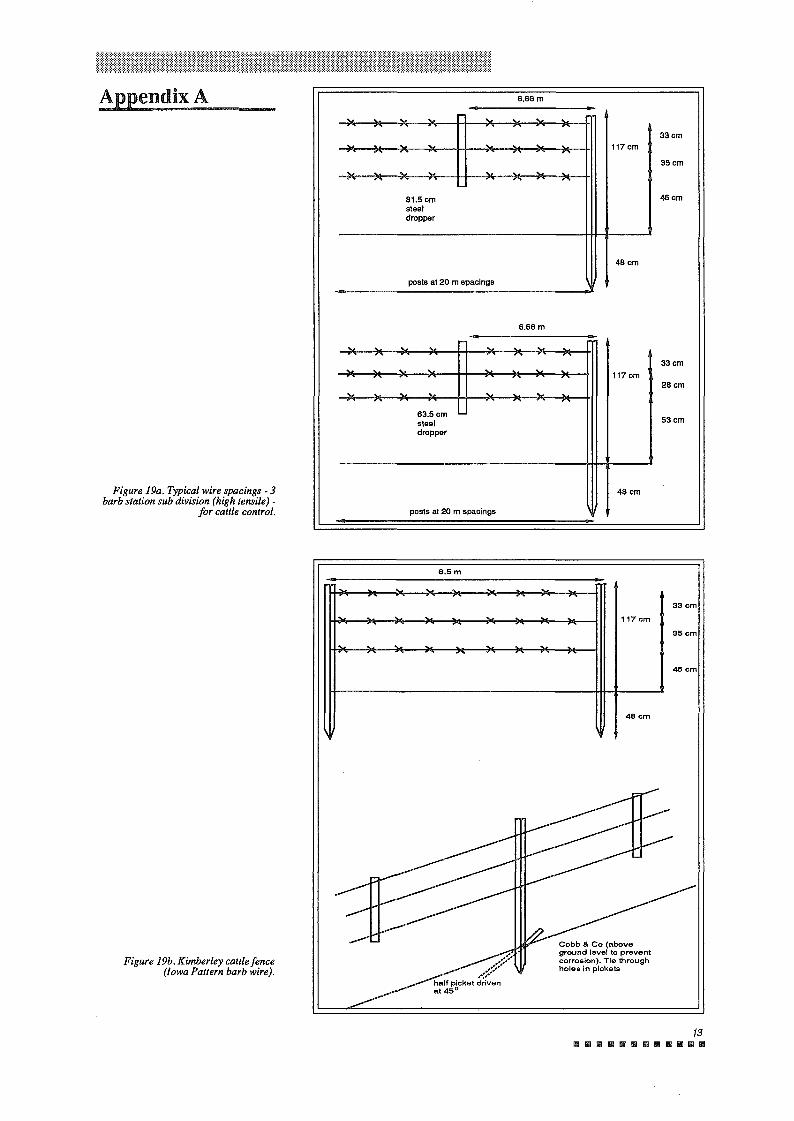
Cobb & Co (above ground level to prevent corrosion). Tie through holes in pickets
~~~::::::: half picket ;;;f ::n at45°
46cm
6.Sm
. . . . 33cm . . . . . 117 cm
35cm .. . . . .. ..... ..... ~ 46cm
posts at 20 m spacings
63.5 cm steel dropper
117cm
53cm
28cm
33cm
46cm
35cm
33cm
48cm
6.66 m
. . . . . . . . " ,... ...
. .. .. . . . 117cm . ..... ~ ---,-,,.
.. . . .. .. .. 81.5cm steel dropper
48cm
posts at 20 m spacings
6.66m
Figure 19b. Kimberley cattle fence (Iowa Pattern barb wire).
Figure 19a. Typical wire spacings - 3 barb station sub division (high tensile) -
for cattle control.
Appendix A
678/10/90/2M
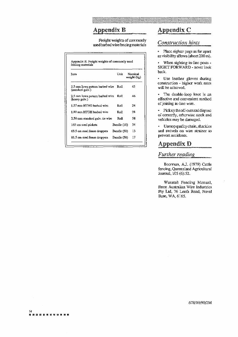
Waratah Fencing Manual, From Australian Wire Industries Pty Ltd, 76 Leath Road, Naval Base, WA, 6165.
Boorman, A.J. (1979) Cattle fencing, Queensland Agricultural Journal, 105 (6):52.
Further reading
AppendixD
• Place sighter pegs as far apart as visibility allows ( about 200 m).
• When sighting in-line posts - SIGHT FORWARD - never look back. • Use leather gloves during construction - higher work rates will be achieved.
• The double-loop knot is an effective and convenient method of joining in-line wire.
• Pickuptheoff-cutsanddispose of correctly, otherwise stock and vehicles may be damaged. • Usetopqualitychain,shackles and swivels on wire strainer to prevent accidents.
Construction hints
Appendix C
Item Unit Nominal weight (kg)
2.5 mm Iowa pattern barbed wire Roll 45 (standard galv.)
2.5 mm Iowa pattern barbed wire Roll 46 (heavy galv.)
1.57 mm HTIIG barbed wire Roll 24
1.80 mm HTGH barbed wire Roll 28
2.50 mm standard galv. tie wire Roll 58
165 cm steel pickets Bundle (10) 34
63.5 cm steel fence droppers Bundle (50) 13
81.5 cm steel fence droppers Bundle (50) 17
Appendix B. Freight weights of commonly used fencing materials
Freight weights of commonly usedbarbedwirefencingmaterials
Appendix B
14 ..............
Related Documents