A guidance law for UAV autonomous aerial refueling based on the iterative computation method Luo Delin a, * , Xie Rongzeng a , Duan Haibin b a Department of Automation, Xiamen University, Xiamen 361005, China b State Key Laboratory of Virtual Reality Technology and Systems, Beihang University, Beijing 100191, China Received 28 July 2013; revised 9 September 2013; accepted 18 October 2013 Available online 4 July 2014 KEYWORDS Autonomous aerial refueling; Aerial rendezvous; Formation control; Guidance law; Unmanned aerial vehicle Abstract The rendezvous and formation problem is a significant part for the unmanned aerial vehicle (UAV) autonomous aerial refueling (AAR) technique. It can be divided into two major phases: the long-range guidance phase and the formation phase. In this paper, an iterative computation guidance law (ICGL) is proposed to compute a series of state variables to get the solu- tion of a control variable for a UAV conducting rendezvous with a tanker in AAR. The proposed method can make the control variable converge to zero when the tanker and the UAV receiver come to a formation flight eventually. For the long-range guidance phase, the ICGL divides it into two sub-phases: the correction sub-phase and the guidance sub-phase. The two sub-phases share the same iterative process. As for the formation phase, a velocity coordinate system is created by which control accelerations are designed to make the speed of the UAV consistent with that of the tanker. The simulation results demonstrate that the proposed ICGL is effective and robust against wind disturbance. ª 2014 Production and hosting by Elsevier Ltd. on behalf of CSAA & BUAA. 1. Introduction With the rapid development of UAV technologies, UAVs are being used to carry out various missions like high altitude surveillance and reconnaissance, long distance military strikes, etc., some of which require UAVs to continuously stay in the air for a quite long time. To this end, autonomous aerial refu- eling (AAR) becomes a key issue to be addressed for these applications of UAV. There are four main tasks to be accom- plished sequentially during AAR of UAV: UAV rendezvous, formation maintaining, pipeline docking, and refueling. This paper mainly focuses on presenting a guidance law for the ren- dezvous and formation maintaining processes. For decades, a lot of achievements have been made to develop guidance tech- nologies for the UAV rendezvous problem. 1–3 One of the most mature technologies is the classical proportional navigation guidance (PNG). 4 After that, many improved proportional * Corresponding author. Tel.: +86 592 2580057. E-mail addresses: [email protected] (D. Luo), xierongzeng [email protected] (R. Xie), [email protected] (H. Duan). Peer review under responsibility of Editorial Committee of CJA. Production and hosting by Elsevier Chinese Journal of Aeronautics, (2014),27(4): 875–883 Chinese Society of Aeronautics and Astronautics & Beihang University Chinese Journal of Aeronautics [email protected] www.sciencedirect.com http://dx.doi.org/10.1016/j.cja.2014.06.003 1000-9361 ª 2014 Production and hosting by Elsevier Ltd. on behalf of CSAA & BUAA.

Welcome message from author
This document is posted to help you gain knowledge. Please leave a comment to let me know what you think about it! Share it to your friends and learn new things together.
Transcript

Chinese Journal of Aeronautics, (2014),27(4): 875–883
Chinese Society of Aeronautics and Astronautics& Beihang University
Chinese Journal of Aeronautics
A guidance law for UAV autonomous aerial
refueling based on the iterative computation
method
* Corresponding author. Tel.: +86 592 2580057.E-mail addresses: [email protected] (D. Luo), xierongzeng
[email protected] (R. Xie), [email protected] (H. Duan).
Peer review under responsibility of Editorial Committee of CJA.
Production and hosting by Elsevier
http://dx.doi.org/10.1016/j.cja.2014.06.0031000-9361 ª 2014 Production and hosting by Elsevier Ltd. on behalf of CSAA & BUAA.
Luo Delin a,*, Xie Rongzeng a, Duan Haibin b
a Department of Automation, Xiamen University, Xiamen 361005, Chinab State Key Laboratory of Virtual Reality Technology and Systems, Beihang University, Beijing 100191, China
Received 28 July 2013; revised 9 September 2013; accepted 18 October 2013Available online 4 July 2014
KEYWORDS
Autonomous aerial refueling;
Aerial rendezvous;
Formation control;
Guidance law;
Unmanned aerial vehicle
Abstract The rendezvous and formation problem is a significant part for the unmanned aerial
vehicle (UAV) autonomous aerial refueling (AAR) technique. It can be divided into two major
phases: the long-range guidance phase and the formation phase. In this paper, an iterative
computation guidance law (ICGL) is proposed to compute a series of state variables to get the solu-
tion of a control variable for a UAV conducting rendezvous with a tanker in AAR. The proposed
method can make the control variable converge to zero when the tanker and the UAV receiver come
to a formation flight eventually. For the long-range guidance phase, the ICGL divides it into two
sub-phases: the correction sub-phase and the guidance sub-phase. The two sub-phases share the
same iterative process. As for the formation phase, a velocity coordinate system is created by which
control accelerations are designed to make the speed of the UAV consistent with that of the tanker.
The simulation results demonstrate that the proposed ICGL is effective and robust against wind
disturbance.ª 2014 Production and hosting by Elsevier Ltd. on behalf of CSAA & BUAA.
1. Introduction
With the rapid development of UAV technologies, UAVs are
being used to carry out various missions like high altitude
surveillance and reconnaissance, long distance military strikes,etc., some of which require UAVs to continuously stay in theair for a quite long time. To this end, autonomous aerial refu-
eling (AAR) becomes a key issue to be addressed for theseapplications of UAV. There are four main tasks to be accom-plished sequentially during AAR of UAV: UAV rendezvous,
formation maintaining, pipeline docking, and refueling. Thispaper mainly focuses on presenting a guidance law for the ren-dezvous and formation maintaining processes. For decades, a
lot of achievements have been made to develop guidance tech-nologies for the UAV rendezvous problem.1–3 One of the mostmature technologies is the classical proportional navigation
guidance (PNG).4 After that, many improved proportional
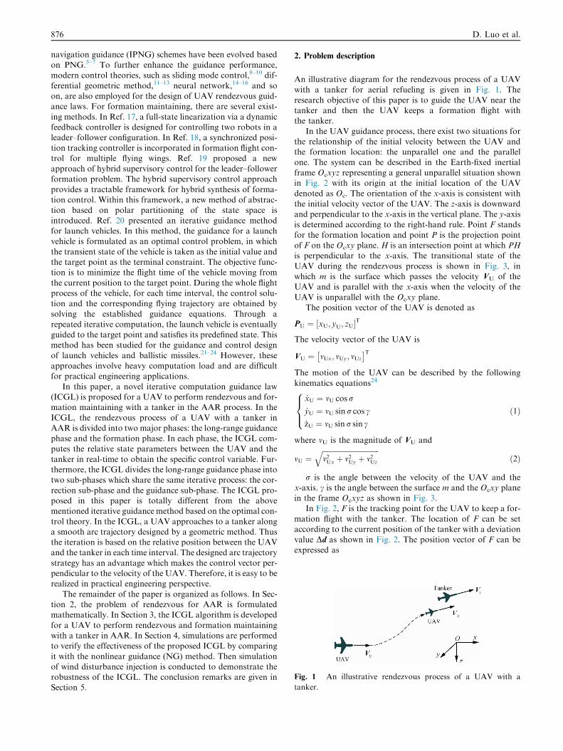
Fig. 1 An illustrative rendezvous process of a UAV with a
tanker.
876 D. Luo et al.
navigation guidance (IPNG) schemes have been evolved basedon PNG.5–7 To further enhance the guidance performance,modern control theories, such as sliding mode control,8–10 dif-
ferential geometric method,11–13 neural network,14–16 and soon, are also employed for the design of UAV rendezvous guid-ance laws. For formation maintaining, there are several exist-
ing methods. In Ref. 17, a full-state linearization via a dynamicfeedback controller is designed for controlling two robots in aleader–follower configuration. In Ref. 18, a synchronized posi-
tion tracking controller is incorporated in formation flight con-trol for multiple flying wings. Ref. 19 proposed a newapproach of hybrid supervisory control for the leader–followerformation problem. The hybrid supervisory control approach
provides a tractable framework for hybrid synthesis of forma-tion control. Within this framework, a new method of abstrac-tion based on polar partitioning of the state space is
introduced. Ref. 20 presented an iterative guidance methodfor launch vehicles. In this method, the guidance for a launchvehicle is formulated as an optimal control problem, in which
the transient state of the vehicle is taken as the initial value andthe target point as the terminal constraint. The objective func-tion is to minimize the flight time of the vehicle moving from
the current position to the target point. During the whole flightprocess of the vehicle, for each time interval, the control solu-tion and the corresponding flying trajectory are obtained bysolving the established guidance equations. Through a
repeated iterative computation, the launch vehicle is eventuallyguided to the target point and satisfies its predefined state. Thismethod has been studied for the guidance and control design
of launch vehicles and ballistic missiles.21–24 However, theseapproaches involve heavy computation load and are difficultfor practical engineering applications.
In this paper, a novel iterative computation guidance law(ICGL) is proposed for a UAV to perform rendezvous and for-mation maintaining with a tanker in the AAR process. In the
ICGL, the rendezvous process of a UAV with a tanker inAAR is divided into two major phases: the long-range guidancephase and the formation phase. In each phase, the ICGL com-putes the relative state parameters between the UAV and the
tanker in real-time to obtain the specific control variable. Fur-thermore, the ICGL divides the long-range guidance phase intotwo sub-phases which share the same iterative process: the cor-
rection sub-phase and the guidance sub-phase. The ICGL pro-posed in this paper is totally different from the abovementioned iterative guidance method based on the optimal con-
trol theory. In the ICGL, a UAV approaches to a tanker alonga smooth arc trajectory designed by a geometric method. Thusthe iteration is based on the relative position between the UAVand the tanker in each time interval. The designed arc trajectory
strategy has an advantage which makes the control vector per-pendicular to the velocity of the UAV. Therefore, it is easy to berealized in practical engineering perspective.
The remainder of the paper is organized as follows. In Sec-tion 2, the problem of rendezvous for AAR is formulatedmathematically. In Section 3, the ICGL algorithm is developed
for a UAV to perform rendezvous and formation maintainingwith a tanker in AAR. In Section 4, simulations are performedto verify the effectiveness of the proposed ICGL by comparing
it with the nonlinear guidance (NG) method. Then simulationof wind disturbance injection is conducted to demonstrate therobustness of the ICGL. The conclusion remarks are given inSection 5.
2. Problem description
An illustrative diagram for the rendezvous process of a UAVwith a tanker for aerial refueling is given in Fig. 1. The
research objective of this paper is to guide the UAV near thetanker and then the UAV keeps a formation flight withthe tanker.
In the UAV guidance process, there exist two situations forthe relationship of the initial velocity between the UAV andthe formation location: the unparallel one and the parallelone. The system can be described in the Earth-fixed inertial
frame Ocxyz representing a general unparallel situation shownin Fig. 2 with its origin at the initial location of the UAVdenoted as Oc. The orientation of the x-axis is consistent with
the initial velocity vector of the UAV. The z-axis is downwardand perpendicular to the x-axis in the vertical plane. The y-axisis determined according to the right-hand rule. Point F stands
for the formation location and point P is the projection pointof F on the Ocxy plane. H is an intersection point at which PHis perpendicular to the x-axis. The transitional state of the
UAV during the rendezvous process is shown in Fig. 3, inwhich m is the surface which passes the velocity VU of theUAV and is parallel with the x-axis when the velocity of theUAV is unparallel with the Ocxy plane.
The position vector of the UAV is denoted as
PU ¼ xU; yU; zU½ �T
The velocity vector of the UAV is
VU ¼ mUx; mUy; mUz
� �T
The motion of the UAV can be described by the following
kinematics equations24
_xU ¼ mU cosr
_yU ¼ mU sin r cos c
_zU ¼ mU sin r sin c
8><>:
ð1Þ
where mU is the magnitude of VU and
mU ¼ffiffiffiffiffiffiffiffiffiffiffiffiffiffiffiffiffiffiffiffiffiffiffiffiffiffiffiffiffiffiffiffim2Ux þ m2Uy þ m2Uz
qð2Þ
r is the angle between the velocity of the UAV and thex-axis. c is the angle between the surface m and the Ocxy planein the frame Ocxyz as shown in Fig. 3.
In Fig. 2, F is the tracking point for the UAV to keep a for-
mation flight with the tanker. The location of F can be setaccording to the current position of the tanker with a deviationvalue Dd as shown in Fig. 2. The position vector of F can be
expressed as
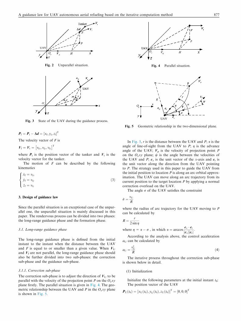
Fig. 2 Unparallel situation.
Fig. 3 State of the UAV during the guidance process.
Fig. 4 Parallel situation.
Fig. 5 Geometric relationship in the two-dimensional plane.
A guidance law for UAV autonomous aerial refueling based on the iterative computation method 877
Pf ¼ Pt � Dd ¼ xf; yf; zf½ �T
The velocity vector of F is
Vf ¼ Vt ¼ mfx; mfy; mfz� �T
where Pt is the position vector of the tanker and Vt is the
velocity vector for the tanker.The motion of F can be described by the following
kinematics
_xf ¼ mfx_yf ¼ mfy_zf ¼ mfz
8><>:
ð3Þ
3. Design of guidance law
Since the parallel situation is an exceptional case of the unpar-allel one, the unparallel situation is mainly discussed in this
paper. The rendezvous process can be divided into two phases:the long-range guidance phase and the formation phase.
3.1. Long-range guidance phase
The long-range guidance phase is defined from the initialinstant to the instant when the distance between the UAV
and F is equal to or smaller than a given value. When VU
and Vf are not parallel, the long-range guidance phase shouldalso be further divided into two sub-phases: the correctionsub-phase and the guidance sub-phase.
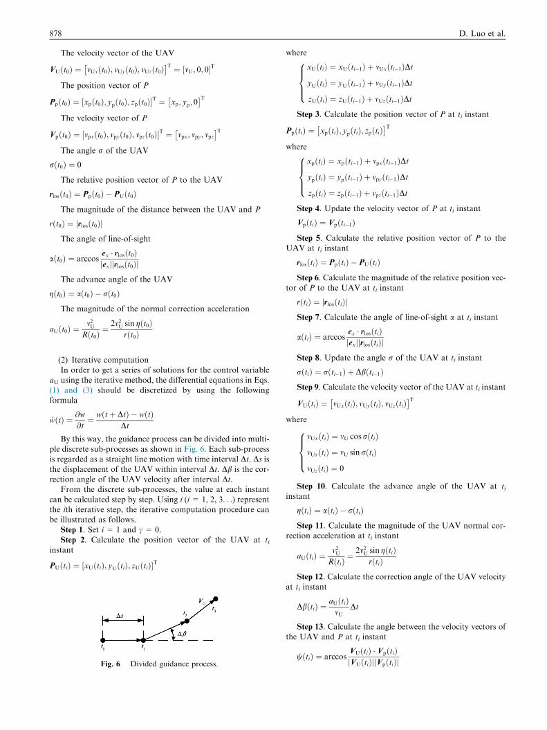
3.1.1. Correction sub-phase
The correction sub-phase is to adjust the direction of VU to be
parallel with the velocity of the projection point P on the Ocxyplane firstly. The parallel situation is given in Fig. 4. The geo-metric relationship between the UAV and P in the Ocxy planeis shown in Fig. 5.
In Fig. 5, r is the distance between the UAV and P; a is theangle of line-of-sight from the UAV to P; g is the advance
angle of the UAV; Vp is the velocity of projection point Pon the Ocxy plane; w is the angle between the velocities ofthe UAV and P; ex is the unit vector of the x-axis and er is
the unit vector along the direction from the UAV pointingto P. The strategy used in this paper to guide the UAV fromthe initial position to location P is along an arc orbital approx-imation. The UAV can move along an arc trajectory from its
current position to the target location P by applying a normalcorrection overload on the UAV.
The angle r of the UAV satisfies the constraint
_r ¼ mUR
where the radius of arc trajectory for the UAV moving to P
can be calculated by
R ¼ r
2 sin g
where g = a � r , in which a ¼ arccosex � erjexjjerj
:
According to the analysis above, the control accelerationaU can be calculated by
aU ¼m2UR
ð4Þ
The iterative process throughout the correction sub-phaseis shown below in detail.
(1) Initialization
Initialize the following parameters at the initial instant t0:
The position vector of the UAV
PUðt0Þ ¼ xUðt0Þ; yUðt0Þ; zUðt0Þ½ �T ¼ 0; 0; 0½ �T
878 D. Luo et al.
The velocity vector of the UAV
VUðt0Þ ¼ vUxðt0Þ; vUyðt0Þ; vUzðt0Þ� �T ¼ vU; 0; 0½ �T
The position vector of P
Ppðt0Þ ¼ ½xpðt0Þ; ypðt0Þ; zpðt0Þ�T ¼ xp; yp; 0
� �T
The velocity vector of P
Vpðt0Þ ¼ ½vpxðt0Þ; vpyðt0Þ; vpzðt0Þ�T ¼ vpx; vpy; vpz� �T
The angle r of the UAV
rðt0Þ ¼ 0
The relative position vector of P to the UAV
rlosðt0Þ ¼ Ppðt0Þ � PUðt0Þ
The magnitude of the distance between the UAV and P
rðt0Þ ¼ rlosðt0Þj j
The angle of line-of-sight
aðt0Þ ¼ arccosex � rlosðt0Þjexj rlosðt0Þj j
The advance angle of the UAV
gðt0Þ ¼ aðt0Þ � rðt0Þ
The magnitude of the normal correction acceleration
aUðt0Þ ¼m2U
Rðt0Þ¼ 2m2U sin gðt0Þ
rðt0Þ
(2) Iterative computationIn order to get a series of solutions for the control variable
aU using the iterative method, the differential equations in Eqs.(1) and (3) should be discretized by using the following
formula
_wðtÞ ¼ @w@t¼ wðtþ DtÞ � wðtÞ
Dt
By this way, the guidance process can be divided into multi-ple discrete sub-processes as shown in Fig. 6. Each sub-processis regarded as a straight line motion with time interval Dt. Ds isthe displacement of the UAV within interval Dt. Db is the cor-rection angle of the UAV velocity after interval Dt.
From the discrete sub-processes, the value at each instant
can be calculated step by step. Using i (i= 1, 2, 3. . .) representthe ith iterative step, the iterative computation procedure canbe illustrated as follows.
Step 1. Set i= 1 and c = 0.
Step 2. Calculate the position vector of the UAV at tiinstant
PUðtiÞ ¼ xUðtiÞ; yUðtiÞ; zUðtiÞ½ �T
Fig. 6 Divided guidance process.
where
xUðtiÞ ¼ xUðti�1Þ þ mUxðti�1ÞDt
yUðtiÞ ¼ yUðti�1Þ þ mUyðti�1ÞDt
zUðtiÞ ¼ zUðti�1Þ þ mUzðti�1ÞDt
8>><>>:
Step 3. Calculate the position vector of P at ti instant
PpðtiÞ ¼ xpðtiÞ; ypðtiÞ; zpðtiÞ� �T
where
xpðtiÞ ¼ xpðti�1Þ þ mpxðti�1ÞDt
ypðtiÞ ¼ ypðti�1Þ þ mpyðti�1ÞDt
zpðtiÞ ¼ zpðti�1Þ þ mpzðti�1ÞDt
8>><>>:
Step 4. Update the velocity vector of P at ti instant
VpðtiÞ ¼ Vpðti�1Þ
Step 5. Calculate the relative position vector of P to theUAV at ti instant
rlosðtiÞ ¼ PpðtiÞ � PUðtiÞ
Step 6. Calculate the magnitude of the relative position vec-
tor of P to the UAV at ti instant
rðtiÞ ¼ rlosðtiÞj j
Step 7. Calculate the angle of line-of-sight a at ti instant
aðtiÞ ¼ arccosex � rlosðtiÞjexj rlosðtiÞj j
Step 8. Update the angle r of the UAV at ti instant
rðtiÞ ¼ rðti�1Þ þ Dbðti�1Þ
Step 9. Calculate the velocity vector of the UAV at ti instant
VUðtiÞ ¼ mUxðtiÞ; mUyðtiÞ; mUzðtiÞ� �T
where
mUxðtiÞ ¼ mU cos rðtiÞ
mUyðtiÞ ¼ mU sinrðtiÞ
mUzðtiÞ ¼ 0
8>><>>:
Step 10. Calculate the advance angle of the UAV at tiinstant
gðtiÞ ¼ aðtiÞ � rðtiÞ
Step 11. Calculate the magnitude of the UAV normal cor-rection acceleration at ti instant
aUðtiÞ ¼m2U
RðtiÞ¼ 2m2U sin gðtiÞ
rðtiÞ
Step 12. Calculate the correction angle of the UAV velocityat ti instant
DbðtiÞ ¼aUðtiÞ
mUDt
Step 13. Calculate the angle between the velocity vectors ofthe UAV and P at ti instant
wðtiÞ ¼ arccosVUðtiÞ � VpðtiÞjVUðtiÞjjVpðtiÞj
A guidance law for UAV autonomous aerial refueling based on the iterative computation method 879
Step 14. If w(ti) is smaller than a given value of 0.0005 radin this paper, terminate the iterative computation and go intothe guidance sub-phase. Otherwise, let i= i+ 1, and go to
step 2.
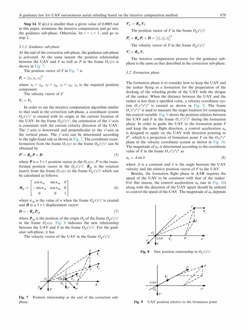
3.1.2. Guidance sub-phase
At the end of the correction sub-phase, the guidance sub-phase
is activated. At the same instant the position relationshipbetween the UAV and F as well as P in the frame Ocxyz isshown in Fig. 7.
The position vector of F in Fig. 7 is
Pf ¼ xf; yf; zf½ �T
where xf = xp, yf = yp, zf = zd, zd is the required positioncomponent.
The velocity vector of F
Vf ¼ Vp
In order to use the iterative computation algorithm similar
to that used in the correction sub-phase, a coordinate systemOgx
0y0z0 is created with its origin at the current location ofthe UAV. In the frame Ogx
0y0z0, the orientation of the x0-axisis consistent with the current velocity direction of the UAV.
The z0-axis is downward and perpendicular to the x0-axis inthe vertical plane. The y0-axis can be determined accordingto the right-hand rule as shown in Fig. 7. The coordinate trans-
formation from the frame Ocxyz to the frame Ogx0y0z0 can be
obtained by
P0 ¼ RgcPþD ð5Þ
where P is a 3 · 1 position vector in the Ocxyz, P0 is the trans-
formed position vector in the Ogx0y0z0. Rgc is the rotation
matrix from the frame Ocxyz to the frame Ogx0y0z0 which can
be calculated as follows:
Rgc ¼cos rog sin rog 0
� sin rog cos rog 0
0 0 1
264
375 ð6Þ
where rog is the value of r when the frame Ogx0y0z0 is created
and D is a 3 · 1 displacement vector:
D ¼ �RgcPog ð7Þ
where Pog is the position of the origin Og of the frame Ogx0y0z0
in the frame Ocxyz. Fig. 8 indicates the new relationshipbetween the UAV and F in the frame Ogx
0y0z0. For the guid-ance sub-phase, it has.
The velocity vector of the UAV in the frame Ogx0y0z0
Fig. 7 Position relationship at the end of the correction sub-
phase.
V0U ¼ RgcVU
The position vector of F in the frame Ogx0y0z0
P0f ¼ RgcPf þD ¼ x0f; y0f; z0f
� �T
The velocity vector of F in the frame Ogx0y0z0
V0f ¼ RgcVf
The iterative computation process for the guidance sub-
phase is the same as that described in the correction sub-phase.
3.2. Formation phase
The formation phase is to consider how to keep the UAV andthe tanker flying in a formation for the preparation of thedocking of the refueling probe of the UAV with the drogue
of the tanker. When the distance between the UAV and thetanker is less than a specified value, a velocity coordinate sys-tem Ovx
00y00z00 is created as shown in Fig. 9. The frameOvx
00y00z00 is used to measure the target location for computing
the control variable. Fig. 9 shows the position relation betweenthe UAV and F in the frame Ovx
00y00z00 during the formationphase. In order to guide the UAV to the formation point F
and keep the same flight direction, a control acceleration anis designed to apply on the UAV with direction pointing toF00, which is a projection of formation point F on the Ovy
00z00
plane in the velocity coordinate system as shown in Fig. 10.The magnitude of an is determined according to the coordinatevalue of F in the frame Ovx
00y00z00 as
an ¼ A sin d ð8Þ
where A is a constant and d is the angle between the UAVvelocity and the relative position vector of F to the UAV.
Besides, the formation flight phase in AAR requires thespeed of the UAV to be consistent with that of the tanker.
For this reason, the control acceleration ab (see in Fig. 10)along with the direction of the UAV speed should be utilizedto control the speed of the UAV. The magnitude of ab depends
Fig. 8 New position relationship in Ogx0y0z0.
Fig. 9 UAV position relative to the formation point.
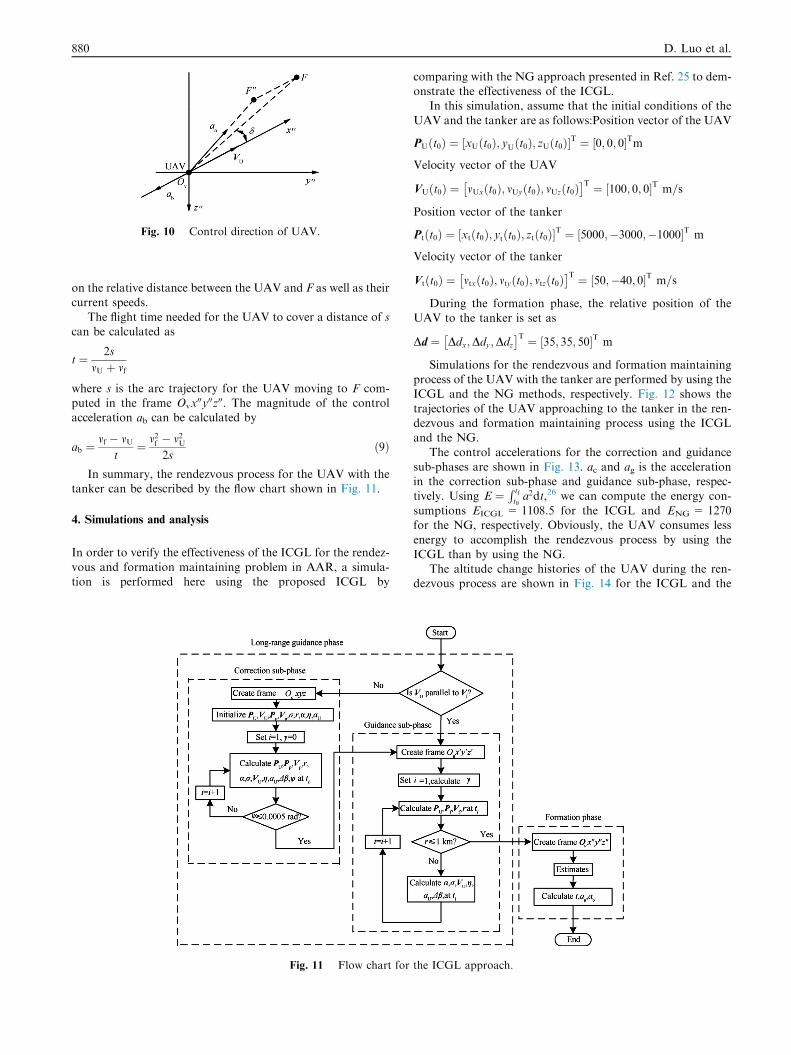
Fig. 10 Control direction of UAV.
880 D. Luo et al.
on the relative distance between the UAV and F as well as theircurrent speeds.
The flight time needed for the UAV to cover a distance of scan be calculated as
t ¼ 2s
mU þ vf
where s is the arc trajectory for the UAV moving to F com-puted in the frame Ovx
00y00z00. The magnitude of the controlacceleration ab can be calculated by
ab ¼mf � mU
t¼ m2f � m2U
2sð9Þ
In summary, the rendezvous process for the UAV with thetanker can be described by the flow chart shown in Fig. 11.
4. Simulations and analysis
In order to verify the effectiveness of the ICGL for the rendez-
vous and formation maintaining problem in AAR, a simula-tion is performed here using the proposed ICGL by
Fig. 11 Flow chart for
comparing with the NG approach presented in Ref. 25 to dem-onstrate the effectiveness of the ICGL.
In this simulation, assume that the initial conditions of the
UAV and the tanker are as follows:Position vector of the UAV
PUðt0Þ ¼ xUðt0Þ; yUðt0Þ; zUðt0Þ½ �T ¼ 0; 0; 0½ �Tm
Velocity vector of the UAV
VUðt0Þ ¼ mUxðt0Þ; mUyðt0Þ; mUzðt0Þ� �T ¼ ½100; 0; 0�T m=s
Position vector of the tanker
Ptðt0Þ ¼ xtðt0Þ; ytðt0Þ; ztðt0Þ½ �T ¼ 5000;�3000;�1000½ �T m
Velocity vector of the tanker
Vtðt0Þ ¼ mtxðt0Þ; mtyðt0Þ; mtzðt0Þ� �T ¼ ½50;�40; 0�T m=s
During the formation phase, the relative position of theUAV to the tanker is set as
Dd ¼ Ddx;Ddy;Ddz� �T ¼ 35; 35; 50½ �T m
Simulations for the rendezvous and formation maintainingprocess of the UAV with the tanker are performed by using theICGL and the NG methods, respectively. Fig. 12 shows the
trajectories of the UAV approaching to the tanker in the ren-dezvous and formation maintaining process using the ICGLand the NG.
The control accelerations for the correction and guidancesub-phases are shown in Fig. 13. ac and ag is the accelerationin the correction sub-phase and guidance sub-phase, respec-tively. Using E ¼
R tft0a2dt,26 we can compute the energy con-
sumptions EICGL = 1108.5 for the ICGL and ENG = 1270for the NG, respectively. Obviously, the UAV consumes lessenergy to accomplish the rendezvous process by using the
ICGL than by using the NG.The altitude change histories of the UAV during the ren-
dezvous process are shown in Fig. 14 for the ICGL and the
the ICGL approach.
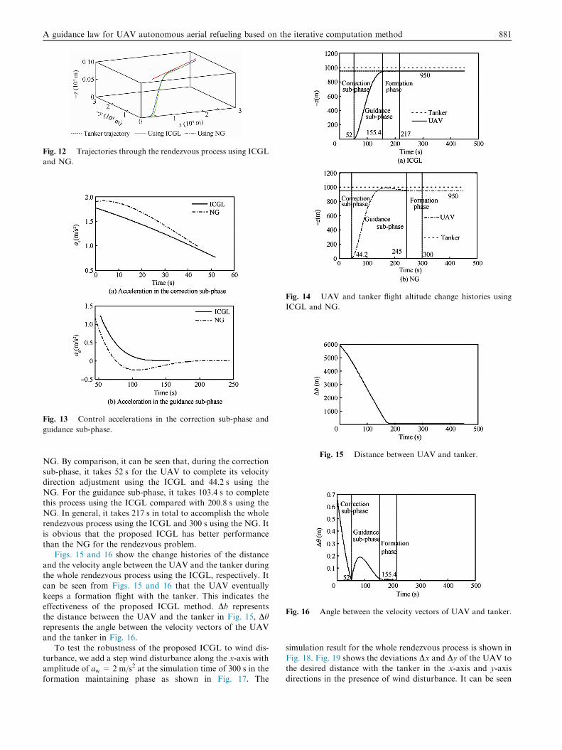
Fig. 12 Trajectories through the rendezvous process using ICGL
and NG.
Fig. 13 Control accelerations in the correction sub-phase and
guidance sub-phase.
ig. 14 UAV and tanker flight altitude change histories using
CGL and NG.
Fig. 15 Distance between UAV and tanker.
Fig. 16 Angle between the velocity vectors of UAV and tanker.
A guidance law for UAV autonomous aerial refueling based on the iterative computation method 881
NG. By comparison, it can be seen that, during the correctionsub-phase, it takes 52 s for the UAV to complete its velocitydirection adjustment using the ICGL and 44.2 s using the
NG. For the guidance sub-phase, it takes 103.4 s to completethis process using the ICGL compared with 200.8 s using theNG. In general, it takes 217 s in total to accomplish the wholerendezvous process using the ICGL and 300 s using the NG. It
is obvious that the proposed ICGL has better performancethan the NG for the rendezvous problem.
Figs. 15 and 16 show the change histories of the distance
and the velocity angle between the UAV and the tanker duringthe whole rendezvous process using the ICGL, respectively. Itcan be seen from Figs. 15 and 16 that the UAV eventually
keeps a formation flight with the tanker. This indicates theeffectiveness of the proposed ICGL method. Db representsthe distance between the UAV and the tanker in Fig. 15, Dhrepresents the angle between the velocity vectors of the UAV
and the tanker in Fig. 16.To test the robustness of the proposed ICGL to wind dis-
turbance, we add a step wind disturbance along the x-axis with
amplitude of aw = 2 m/s2 at the simulation time of 300 s in theformation maintaining phase as shown in Fig. 17. The
F
I
simulation result for the whole rendezvous process is shown inFig. 18. Fig. 19 shows the deviations Dx and Dy of the UAV tothe desired distance with the tanker in the x-axis and y-axis
directions in the presence of wind disturbance. It can be seen

Fig. 19 Distance between UAV and tanker on.
Fig. 20 Control acceleration of UAV under wind disturbance.
Fig. 17 A step wind disturbance.
Fig. 18 Trajectories of the rendezvous process against wind
disturbance.
882 D. Luo et al.
that the steady state error is about 2 m in the x-axis direction
and less than 3 m in the y-axis direction. Fig. 20 shows thechange of the control acceleration ad of the UAV under winddisturbance. The simulation result indicates that the proposedICGL has good robustness against wind disturbance.
5. Conclusions
(1) A guidance approach of the ICGL addressing the ren-dezvous and formation problem for a UAV in AAR ispresented in this paper. The ICGL divides the wholeprocess into two phases: the long-range guidance phase
and the formation phase, in which the long-range guid-ance phase is further divided into two sub-phases: thecorrection sub-phase and the guidance sub-phase.
(2) The ICGL solves the guidance problem of each phaseand sub-phase in a two-dimensional space with the iter-ative method to obtain the control acceleration for the
UAV.(3) Simulation results demonstrate that the proposed ICGL
is effective for the UAV to deal with the rendezvous and
formation problem in AAR and is robust against winddisturbance.
Acknowledgements
We would like to thank the anonymous reviewers for their
constructive comments on this manuscript. This study was par-tially supported by the National Natural Science Foundationof China (No. 61333004), partially by the Aeronautical Science
Foundation of China (No. 20115868009), and partially by theopen funding project of the State Key Laboratory of VirtualReality Technology and Systems at Beihang University of
China (No. BUAA-VR-13KF-01).
References
1. Luo DL, Lu TX, Wu SX. A survey on guidance laws for flight
vehicle. J Syst Simul 2010;22(S1):16–20 [Chinese].
2. Guo J, Dong XM, Xu YJ, Liao KJ. Design of UAV autonomous
controller for rendezvous in aerial refueling. Contr Decis
2010;25(4):567–71 [Chinese].
3. Liang X, Wang HL, Li DW, Lv WT. Three-dimensional path
planning for unmanned aerial vehicles based on principles of
stream avoiding obstacles. Acta Aeronaut Astronaut Sin
2013;34(7):1670–81 [Chinese].
4. GuelmanM. A qualitative study of proportional navigation. IEEE
Trans Aerosp Electron Syst 1971;7(4):337–43.
5. Tyan F. Capture region of a GIPN guidance law for missile and
target with bounded maneuverability. IEEE Trans Aerosp Electron
Syst 2011;47(1):201–13.
6. Lin CL, Li YH. Development of 3-D modified proportional
navigation guidance law against high-speed targets. IEEE Trans
Aerosp Electron Syst 2013;49(1):677–87.

A guidance law for UAV autonomous aerial refueling based on the iterative computation method 883
7. Zhao SY, Zhou R, Wei C, Ding QX. Design of time-constrained
Guidance Laws via virtual leader approach. Chin J Aeronautics
2010;23(1):103–8.
8. Yamasaki T, Balakrishnan SN, Takano H. Integrated guidance
and autopilot design for a chasing UAV via high-order sliding
modes. J Franklin Inst 2012;349(2):531–58.
9. Miao SQ, Cong BL, Liu XD. Adaptive sliding mode control of
flexible spacecraft on input shaping. Acta Aeronaut Astronaut Sin
2013;34(8):1906–14 [Chinese].
10. Wang L, Li GC, Wang ZL, Jiao B. Sliding mode control of an
under actuated quadrotor UAV. J Harbin Eng Univ
2012;33(10):1248–53.
11. Jing WX, Li CY, Qi ZG. Application of the 3D differential
geometric guidance commands. J Astronaut 2007;28(5):1235–40
[Chinese].
12. Peng SC, Pan L, Han DP, Shen LC. A new 3D guidance law based
on nonlinear method. Acta Aeronaut Astronaut Sin
2010;31(10):2018–25 [Chinese].
13. Li J, An HL, Xiang XJ, Shen LC. UAVs formation rendezvous
method based on differential geometry and Lie group. J Natl Univ
Def Technol 2013;35(6):157–64 [Chinese].
14. Li XS, Li X. Robust adaptive backstepping design for unmanned
aerial vehicle formation guidance and control. J Appl Sci
2012;30(5):552–8 [Chinese].
15. Xia QY, Xu JF. A design of triaxial unmanned rotor aircraft and
its adaptive flight control system. Acta Aeronaut Astronaut Sin
2013;34(3):495–508 [Chinese].
16. Luo YL, Yin CX. Study of small UAV control system based on
fuzzy RBF neural network. J Civil Aviat Flight Univ China
2014;25(1):46–9 [Chinese].
17. Hassan GM, Yahya KM, Haq IU. Leader-follower approach
using full-state linearization via dynamic feedback. Proceedings of
the International Conference on Emerging Technologies; 2006 Nov
13–14; Peshawar, Pakistan; 2006. p. 297–305.
18. Linorman NHM, Liu HHT. Formation UAV flight control using
virtual structure and motion synchronization. Proceedings of the
American Control Conference; 2008 Jun 11–13; Seattle, WA, USA;
2008. p. 1782–7.
19. Karimoddini A, Lin H, Chen BM, Lee TH. Hybrid three-
dimensional formation control for unmanned helicopters. Autom-
atica 2013;49(2):424–33.
20. Han ZZ. An iterative guidance method for the large launch
vehicle. J Astronaut 1983;1:9–21 [Chinese].
21. Fu Y, Chen G, Lu BG, Guo JF, Cui NG. A vacuum adaptive
iterative guidance method of launch vehicle based on optimal
analytical solution. Acta Aeronaut Astronaut Sin 2011;32(9):
1696–704 [Chinese].
22. Song ZY. From accurate, precise to perfect-manned space
promotes the development of guidance method on launch vehicle.
Aerosp Contr 2013;31(1):4–10 [Chinese].
23. Xiao LX, Wang JP, Wang AM, Yang J. Optimal iterative
guidance method based on required trajectory. Aerosp Shanghai
2012;29(3):1–5 [Chinese].
24. Chandler DC, Smith IE. Development of the iterative guidance
mode with its application to various vehicles and missions. J
Spacecraft Rockets 1967;4(7):898–903.
25. Park S, Deysty J, How JP. A new nonlinear guidance logic for
trajectory tracking. Proceedings of the AIAA Guidance, Navigation,
and Control Conference and Exhibit; 2004 Aug 16–19; Providence,
Rhode Island, USA; 2004. p. 16–9.
26. Luo DL, Li YF, Wu WH, Shen CL. Terminal guidance law based
on receding horizon control for homing missile. J Nanjing Univ
Aeronaut Astronaut 2005;37(1):52–6 [Chinese].
Luo Delin received Ph.D. degree in navigation, guidance and control
from Nanjing Universtiy of Aeronautics and Astronautics in 2006. He
is presently an associate professor with the Department of Automa-
tion, School of Information Science and Technology, Xiamen Uni-
versity. His research interests include flight vehicle guidance and
control, UAV cooperative control and decision making.
Xie Rongzeng received B.S. degree in automation from Wuhan Uni-
versity of Technology in 2010. Currently, he is a M.S candidate at the
Department of Automation, Xiamen University. His research interests
include UAV guidance and cooperative control.
Duan Haibin received Ph.D. degree in control theory and control
engineering from Nanjing Universtiy of Aeronautics and Astronautics
in 2005. He is currently a professor with the School of Automation
Science and Electrical Engineering, Beihang University. His research
interest include flight control, autonomous control of multiple aerial
vehicles, computational intelligence.
Related Documents