A, GROUP 3 REAR AXLE CONTENTS REAR AXLE ASSEMBLY (BW) RING GEAR 5 REAR AXLE NOISE DIAGNOSIS 2 SERVICE DIAGNOSIS 1 Condition REAR WHEEL NOISE SCORING OF (a) Insufficient lubrication. DIFFERENTIAL GEARS AND PINIONS TOOTH BREAKAGE (RING (a) Overloading. GEAR AND PINION) (b) Erratic clutch operation. (c) Ice-spotted pavements. (d) Improper adjustment. Page SPECIFICATIONS 23 SURE-GRIP DIFFERENTIAL .. 19 TIGHTENING REFERENCE .. 23 Correction (a) Tighten loose wheel nuts. (b) Check rear wheel bearings. If spaded or worn, replace. (c) Defective or brinelled bearings must be replaced. Check rear axle shaft end play. (d) Readjust axle shaft end play. (e) Replace bent or sprung axle shaft. (a) Replace scored gears. Scoring marks on the pressure face of gear teeth or in the bore are caused by instan- taneous fusing of the mating surfaces. Scored gears should be replaced. Fill rear axle to required capacity with proper lubricant. See Specification section. (b) Replace scored gears. Inspect all gears and bearings for possible dam- age. Clean out and refill axle to re- quired capacity with proper lubricant. See Lubrication section. (c) Replace scored gears. Inspect all gears, pinion bores and shaft for scoring, or bearings for possible dam- age. Service as necessary. (a) Replace gears. Examine other gears and bearings for possible damage. Replace parts as needed. Avoid Over- loading. (b) Replace gears, and examine remain- ing parts for possible damage. Avoid erratic clutch operation. (c) Replace gears. Examine remaining parts for possible damage. Replace parts as required. (d) Replace gears. Examine other parts for possible damage. Make sure ring gear and pinion backlash is correct. SERVICE DIAGNOSIS .. Possible Cause (a) Wheel Loose. (b) Spalled wheel bearing cup or cone. (c) Defective, brinelled wheel bearing. (d) Excessive axle shaft end play. (e) Bent or sprung axle shaft flange. (b) Improper grade of lubricant. (c) Excessive spinning of one wheel. REAR AXLE NOISE (a) Insufficient lubricant. (a) Refill rear axle with correct amount of the proper lubricant. See Specifica- tion section. Also check for leaks and correct as necessary. (b) Improper ring gear and pinion adjust- (b) Check ring gear and pinion tooth ment. contact. (c) Unmatched ring gear and pinion. (c) Remove unmatched ring gear and pinion. Replace with a new matched gear and pinion set. (d) Worn teeth on ring gear or pinion. (d) Check teeth on ring gear and pinion for contact. If necessary, replace with new matched set.

Welcome message from author
This document is posted to help you gain knowledge. Please leave a comment to let me know what you think about it! Share it to your friends and learn new things together.
Transcript

A, GROUP 3
REAR AXLE CONTENTS
REAR AXLE ASSEMBLY (BW) RING GEAR 5 REAR AXLE NOISE DIAGNOSIS 2 SERVICE DIAGNOSIS 1
Condition
REAR WHEEL NOISE
SCORING OF (a) Insufficient lubrication. DIFFERENTIAL GEARS AND PINIONS
TOOTH BREAKAGE (RING (a) Overloading. GEAR AND PINION)
(b) Erratic clutch operation.
(c) Ice-spotted pavements.
(d) Improper adjustment.
Page SPECIFICATIONS 23 SURE-GRIP DIFFERENTIAL . . 19 TIGHTENING R E F E R E N C E . . 23
Correction
(a) Tighten loose wheel nuts. (b) Check rear wheel bearings. If spaded
or worn, replace. (c) Defective or brinelled bearings must
be replaced. Check rear axle shaft end play.
(d) Readjust axle shaft end play. (e) Replace bent or sprung axle shaft.
(a) Replace scored gears. Scor ing marks on the pressure face of gear teeth or in the bore are caused by instantaneous fusing of the mating surfaces. Scored gears should be replaced. Fill rear axle to required capacity with proper lubricant. S e e Specif ication section.
(b) Replace scored gears. Inspect all gears and bearings for possible damage. Clean out and refill axle to required capacity with proper lubricant. S e e Lubrication section.
(c) Replace scored gears. Inspect all gears, pinion bores and shaft for scoring, or bearings for possible damage. Service a s necessary.
(a) Replace gears. Examine other gears and bearings for possible damage. Replace parts as needed. Avoid Overloading.
(b) Replace gears, and examine remaining parts for possible damage. Avoid erratic c lutch operation.
(c) Replace gears. Examine remaining parts for possible damage. Replace parts as required.
(d) Replace gears. Examine other parts for possible damage. Make sure ring gear and pinion backlash is correct.
SERVICE DIAGNOSIS .. Possible Cause
(a) Wheel Loose. (b) Spal led wheel bearing cup or cone.
(c) Defective, brinelled wheel bearing.
(d) Excess ive axle shaft end play. (e) Bent or sprung axle shaft flange.
(b) Improper grade of lubricant.
(c) Excess ive spinning of one wheel .
REAR AXLE NOISE (a) Insufficient lubricant. (a) Refill rear axle with correct amount of the proper lubricant. See Speci f ication section. Also check for leaks and correct as necessary.
(b) Improper ring gear and pinion adjust- (b) Check ring gear and pinion tooth ment. contact.
(c) Unmatched ring gear and pinion. (c) Remove unmatched ring gear and pinion. Replace with a new matched gear and pinion set.
(d) Worn teeth on ring gear or pinion. (d) Check teeth on ring gear and pinion for contact. If necessary, replace with new matched set.

3-2 REAR AXLE A
Condition ^ Possible Cause Correction
(e) End play in drive pinion bearings. (e) Adjust drive pinion bearing preload. (f) Side play in differential bearings. (f) Adjust differential bearing preload. (g) Sure-Grip Differential moan and chat- (g) Drain and flush lubricant. See pra
ter, cedure in Sure-Grip section of Group
LOSS OF LUBRICANT (a) Lubricant level too high.
(b) Worn axle shaft oil seals.
OVERHEATING OF UNIT
REAR AXLE NOISE DIAGNOSIS
Most rear axle failures are relatively simple to locate and correct, although rear axle noise is a l i t t l e more difficult to diagnose and make the necessary repairs. The most essential part of rear axle service is proper diagnosis of the problem.
A l l rear axles are noisy to a certain degree. Gear noise is usually associated w i th older axles, but this is not always true. New axles can also be noisy i f they are not properly adjusted or lack lubricat ion. Usually when new improper ly set gears are noisy; the disturbing noise cannot be "adjusted ou t " once the gears are broken in . Recent experience has shown that axle gears can often be readjusted to reduce excessive gear noise, i f they have been operated at normal break-in speeds for less than 500 miles. Regardless of what you've heard to the contrary, noisy gears w i l l not get quieter w i th added mileage . . . they w i l l stay the same or get worse.
Slight axle noise heard only at certain speeds or under remote conditions must be considered normal. Axle noise tends to "peak" at varying speeds and the noise is i n no way indicative of trouble i n the axle.
I f axle noise is present i n an objectionable form, loud or at a l l speeds, an effort should be made to isolate the noise as being i n one part icular un i t of the ve-
(a) Drain excess lubricant by removing filler plug and allow lubricant to level at lower edge of filler plug hole.
(b) Replace worn oil seals with new ones. Prepare new seals before replacement.
(c) Repair or replace housing as required. (d) Replace worn drive pinion oil seal
with a new one. (e) Replace worn or scored companion
flange and oil seal. (f) Clean breather thoroughly. (g) Tighten bolts or cover screws to spec
ifications and fill to correct level with proper lubricant.
(a) Refill rear axle. (b) Drain, flush and refill rear axle with
correct amount of the proper lubricant. See Specification Section.
(c) Readjust bearings. (d) Check gears for excessive wear or
scoring. Replace as necessary. (e) Readjust ring gear and pinion back
lash and check gears for possible scoring.
h ide . Many noises, reported as coming f rom the rear axle actually originate f rom other sources such as tires, road surfaces, wheel bearings, engine, transmission, exhaust, propeller shaft vibration, universal jo int noise or body drumming. A thorough and careful check should be made to determine the source of the noise before any disassembly and teardown of the rear axle is attempted.
The complete isolation of noise i n any one uni t requires considerable sk i l l and previous experience. El iminat ing certain type noises often baffle even the most experienced personnel. Often such practices as raising t i re pressures to eliminate t i re noise, l istening for the noise at varying speeds under different load conditions such as; drive, float and coast, and under certain highway conditions, turn ing the steering wheel f rom left to r ight to detect wheel bearing noise, w i l l aid even the beginner i n detecting certain alleged axle noises. Axle noises normally fa l l into two categories: gear noise and bearing noise.
To make a good diagnostic check for rear axle noise, a thorough road test is necessary. Select a level smooth blacktop or asphalt road. This w i l l reduce t ire noise and body drumming. Drive the car far enough to thoroughly warm up the axle to normal operating temperature.
Drive the car and note speed at which noise occurs.
(c) Cracked rear axle housing. (d) Worn drive pinion oil seal.
(e) Scored and worn companion flange.
(f) Clogged breather. (g) Loose carrier housing bolts or hous
ing cover screws.
(a) Lubricant level too low. (b) Incorrect grade of lubricant.
(c) Bearings adjusted too tightly. (d) Excessive wear in gears.
(e) Insufficient ring gear to pinion clearance.

A —
Then stop car and, w i th clutch disengaged or automatic transmission i n neutral, r u n engine slowly up and down through engine speeds, corresponding to car speed at which noise was most pronounced, to determine i f i t is caused by exhaust roar, or other engine conditions. Repeat, while engaging and disengaging clutch (transmission in neutral), to determine i f noise can only be isolated by removing propeller shaft and operating transmission i n high).
TIRE NOISE
Tire noise is often mistaken for rear axle noise even though the noisy tires may be located on the front wheels. Tires that are unbalanced or worn unevenly or have surfaces of non-skid type design, or worn in a saw tooth fashion are usually noisy and often produce noises that seem to originate in the rear axle.
Tire noise changes wi th different road surfaces, but rear axle noise does not. Inflate a l l tires to approximately 50 pounds pressure (for test purposes only). This w i l l materially alter noise caused by tires, but w i l l not affect noise caused by rear axle. Rear axle noise usually ceases when coasting at speeds under 30 miles per hour; however, t i re noise continues, but w i th lower tone, as car speed is reduced. Rear axle noise usually changes when comparing drive and coast, but t ire noise remains about the same.
Distinguish between t i re noise and differential noise by noting i f noise varies w i th various speeds or sudden acceleration and deceleration; exhaust and axle noise show variations under these conditions while t i re noise remains constant and is more pronounced at speeds of 20 to 30 miles per hour. Further check for t i re noise by dr iv ing car over smooth pavements or d i r t roads (not gravel) w i th tires at normal pressure. I f noise is caused by tires, i t w i l l noticeably change or disappear and reappear w i th changes i n road surface.
FRONT WHEEL BEARING NOISE
Loose or rough front wheel bearings w i l l cause noise which may be confused w i t h rear axle noises; however, front wheel bearing noise does not change when comparing drive and coast. L ight application of brake while holding car speed steady w i l l often cause wheel bearing noise to diminish, as this takes some weight off the bearing. Front wheel bearings may be easily checked for noise by jacking up the wheels and spinning them, also by shaking wheels to determine i f bearings are loose.
Rear suspension rubber bushings and spring insulators help to dampen out rear axle noise when properly and correctly installed. Check to see that no metallic interference exists between the springs and springs hangers, shackles or " U " bolts. Metal to metal contact
REAR AXLE 3-3
at those points may result i n telegraphing road noise and normal axle noise which would not be objectionable i f properly installed and tightened to specifications.
GEAR NOISE
Abnormal gear noise can be recognized easily because i t produces a cycling tone and w i l l be very pronounced through the speed range i n which i t occurs. Gear noise may be developed under one or more of the fol lowing conditions, "dr i ve " , " road load", " f loat" or "coast". Gear noise usually tends to peak in a narrow speed range or ranges. Gear noise is more prominent between 30 to 40 mph and 50 to 60 mph. Abnormal gear noise is quite rare and i f present i t usually originates f rom scoring of the r ing and drive pinion gear as a result of insufficient or improper lubrication of the axle assembly. The differential side gears and pinions very seldom cause trouble as they are only under loads when the rear wheels travel at different speeds; such as when turn ing corners.
When objectionable axle noise is heard, note the dr iv ing condition and speed range. Remove the differential and carrier f rom the axle housing on the 8-3/4" axle. Perform a tooth contact pattern check to determine i f the best possible pattern has been obtained. I f pattern is found to be unacceptable, reshim and adjust to obain the best possible pattern. I f after readjustment noise s t i l l persists, replace w i th new gear set.
PRE-DISASSEMBLY INVESTIGATION A close examination of the rear axle assembly pr ior
to disassembly can reveal valuable information as to the extent and type of repairs or adjustments necessary. This information coupled w i th the road test results w i l l provide a basis for determining the degree of disassembly required. Since the most frequent causes of axle noise are improper backlash or different ia l bearing preload, or both, a few simple adjustments may be a l l that is necessary to correct the complaint.
Therefore, before disassembly the following checks should be made; drive gear and pinion backlash, pinion bearing preload, and tooth contact pattern and these results recorded and analyzed. I t is felt that these measurements and their results w i l l aid you i n making the necessary repairs to the axle assembly.
BEARING NOISE (DRIVE PINION AND DIFFERENTIAL)
Defective or damaged bearings generally produce a rough growl or grat ing sound, that is constant i n pitch and varies w i th the speed of the vehicle. This fact w i l l allow you to diagnose between bearing noise and gear noise.

3-4 REAR AXLE :
Drive pinion bearing noise result ing f rom defective or damaged bearings can usually be identified by a constant rough sound. Front pinion bearing noise is usually most pronounced on "coast", whereby rear pinion bearing is loudest on "dr i ve " . Pinion bearings are rotat ing at a higher rate of speed than the differential side bearings or the axle shaft bearings. These particular noises can be picked up best by road testing the vehicle i n question on a smooth road (black top). However, extreme caution should be taken not to confuse t i re noise w i th bearing or gear noise. I f doubt should exist t i re treads should be examined for i rregularities that w i l l often produce such noise.
Differential bearing noise w i l l usually produce a constant rough tone which is much slower than the noise caused by the pinion bearings.
REAR WHEEL BEARING NOISE
Defective or damaged rear wheel bearings produce a vibration or growl which continues w i th car coasting and transmission in neutral . A brinneled rear wheel bearing causes a wh i r r ing noise. Spalled rear wheel bearings normally produce a noise similar to a growl, created f rom either flaked or pitted rol lers or bearings races. Unless the damage is severe, rear axle bearing noise is seldom heard above 30 mph.
To differentiate between wheel bearings and gear noise, road test the vehicle on a smooth road (blacktop) at medium and low speed. W i t h traffic permit t ing, swerve the vehicle sharply r ight to left. I f the noise i n question is caused by wheel bearings, i t w i l l usually increase when the vehicle is swerved and w i l l probably be coming f rom the bearing on the loaded side. I f the noise in question cannot be isolated an inspect ion of bearings w i l l be necessary.
KNOCK AT LOW S P E E D S
Low speed knock is usually caused by brinneled universal joints or differential side gear hub to coun-terbore clearance being too great. Inspect and replace universal jo in t or differential case and side gear as required.
DRIVE -LINE SNAP
A snap on a sudden start, either forward or reverse, may be caused by a loose companion flange. Remove the propeller shaft and flange and reinstal l 180 degrees f rom original position. Pinion bearing preload
A
and pinion nut torque must be reset to original settings upon reinstallation.
BACKLASH CLUNK
Excessive clunk on acceleration and deceleration can be caused by anyone of the fol lowing items or a combination; (excessive clearance between) (1) Differential pinion shaft to differential case, (2) Axle shaft to differential side gear splines, (3) Differential side gear hub to differential case counterbore, (4) Different ia l side gear to pinion, (5) Worn thrust washers, (6) Drive gear backlash. Measure and inspect components and replace as required and/or adjust to proper specifications.
ENGINE AND TRANSMISSION NOISE
Sometimes noises which seem to originate in the rear axle are actually that of the engine or transmission. To diagnose which uni t is actually causing the noise, observe the approximate vehicle speed and conditions under which the noise is most pronounced; stop the vehicle in a quiet place to avoid any interfering noises. W i th engine running and transmission i n neutral, r u n engine slowly up and down through engine speeds corresponding to approximate car speed at which the noise was most pronounced. I f a noise similar is produced in this manner i t usually can be assumed that the noise was caused by the engine or transmission and not that of the rear axle.
PROPELLER SHAFT VIBRATION
Objectional vibrations at high speed (65 MPH or higher) may be caused by a propeller shaft that is out of balance or worn universal joints. Out of balance may be due to a damaged or bent shaft.
To determine whether propeller shaft is causing the vibration in question; road test the vehicle through speed range and note speed at which vibration is most pronounced. Shift transmission into lower gear range and drive car at same engine speed as when vibrat ion was most pronounced i n direct drive and note any effect on vibration.
I f the vibration is s t i l l present at the same engine speed, whether i n direct drive or i n the lower gear, since the propeller shaft speed varies, this cannot be the fault. I f the vibrat ion decreases or is eliminated i n the lower gear, then propeller shaft is at fault and should be rebalanced or replaced.

A- REAR AXLE 3-5
REAR AXLE ASSEMBLY ZVa RING GEAR INDEX
Page Axle Shafts and Bearings . . . . . . . . . . . . . . . . . . . . . . 6 Axle Shaft End Play 9 Differential and Carrier (Removal) 10 Differential and Carrier (Installation) 18 Differential Case 11 Drive Gear and Pinion Back lash 17 Gear Tooth Contact Pattern . . . . . . . . . . . . . . . . . . . . 17 Lubrication 18 Pinion Bearing Cup Installation . . . . . . . . 13
GENERAL INFORMATION
The 8 -3 /4" Rear Axle Assembly shown in (Fig. 1), is a semi-floating type and may be divided into four subassemblies; flanged axle drive shafts w i th related parts (Fig. 2.) differential w i th drive gear, drive pinion wi th carrier, and the axle housing. Servicing of the above mentioned subassemblies, w i th exception of the axle housing may be performed without removing the complete rear axle assembly f rom the vehicle.
Gear ratio identification numbers w i l l be stamped on a metal tag and attached by means of the rear axle housing-to-carrier bolt.
Some 8 -3 /4" large stem differential and carrier assemblies have incorporated a collapsible spacer which bears against the inner races of the front and rear bearing. This collapsible spacer is used to establish
BUMPER
H O U S I N G
T E E
W A S H E R
S U P P O R T ' N B O L T
*r* " - G A S K E T
Page Pinion Bearing Preload and Pinion Depth of
Mesh Setting Using Tool C-758-D4 . . . . . . . . . . . . 14 Large Stem Pinion Depth of Mesh 14 Depth of Mesh
Setting Without Using Tool C-758-D4 16 Rear Axle Housing 9 Removal and Replacement of Drive Pinion
Flange and Oil Sea l in Vehicle 18
preload on the pinion bearings. Adjustment of pinion depth of mesh is obtained by
placing a machined shim between the pinion head and the rear pinion bearing cone.
The differential bearings are larger on both the conventional and Sure-Grip Differentials and are not interchangeable w i th previous years bearings.
The Sure-Grip Differential is available as optional equipment in the 8 -3 /4" rear axle assembly. The new Sure-Grip Differential is of a two piece construction similar to the old type and is completely interchangeable w i th the previous type and w i l l be serviced as a complete assembly only. Refer to the "Sure Grip Diff e rent ia l " Section of the Axle Group for the servicing procedure.
S C R E W
A D J U S T E R
S H A F T
BOLT R I G H T
G A S K E T
N U T
C A R R I E R A N D C A P
F L A N G E
O I L S E A L
C O L L A R
G A S K E T
L E F T O I L S E A L
RETAINER '
S H A F T
S T U D
NK967B
Fig. 1—8-3/4" Rear Axle Assembly

3-6 REAR AXLE A
SHOULD T H E REAR A X L E BECOME SUBMERGED E A R L Y A X L E F A I L U R E RESULTING FROM CON-IN WATER, T H E LUBRICANT MUST BE CHANGED TAMINATION OF T H E LUBRICANT BY W A T E R IMMEDIATELY TO AVOID T H E POSSIBILITY OF DRAWN INTO T H E VENT.
SERVICE PROCEDURES
AXLE SHAFTS AND BEARINGS
CAUTION: It is absolutely necessary that anytime an axle assembly is serviced, and the axle shafts are loosened and removed, the axle shaft gaskets and inner axle shaft oil seals must be replaced.
The service procedures for the removal and installation of the axle shaft bearings and collars differ on the Imperial , due to a change i n the material hardness of the collar. I t w i l l be necessary that this procedure be followed to assure that axle shaft is not damaged i n any way dur ing the servicing.
Removal (All models) (1) W i th wheels removed, remove clips holding
brake d rum on axle shaft studs and remove brake drum.
(2) Using access hole i n axle shaft flange, remove retainer nuts, the r ight shaft w i th threaded adjuster in retainer plate w i l l have a lock under one of the studs that should be removed at this time.
(3) Attach axle shaft remover Tool C-3971 (Fig. 3) use Tool C-3971 and adapter SP-5168 on Imperia l only, to axle shaft flange and remove axle shaft. Remove brake assembly and gaskets.
(4) Remove axle shaft o i l seal f rom axle housing using Tool C-637 (Fig. 4).
(5) Wipe axle housing seal bore clean and instal l a new axle shaft o i l seal using Tool C-839 (Fig. 5).
Disassembly (All Models except Imperial) CAUTION: To prevent the possibility of damaging axle shaft seal surface, slide protective sleeve SP-5041 over the seal surface next to bearing collar. CAUTION: Under no circumstances should axle shaft collars or bearings be removed using a torch. The
FLANGE
A D J U S T E R
i SHAFT
i ! £ ! J l LOCK S E A L
C J P / C O L L A R
BEARING
use of a torch in the removal of the axle shaft collars or bearings is an unsafe practice, because heat is fed into the axle shaft bearing journal and thereby weakens this area.
(1) Position axle shaft bearing retaining collar on a heavy vise or anvi l and using a chisel, cut deep grooves into retaining collar at 90° intervals (Fig. 6). This w i l l enlarge bore of collar and permit i t to be driven off of axle shaft.
(2) Remove bearing rol ler retainer flange by cutt ing off lower edge w i th a chisel (Fig. 7).
(3) Gr ind a section off flange of inner bearing cone (Fig. 8) and remove bearing rol lers (Fig. 9).
(4) Pul l bearing rol ler retainer down as far as pos-ADAPTER SP-5021 y x
SCREWS \ > S X SP-5026
BLOCKS BEARING REMOVING SP-5020
>*4
» WASHERS
SP-320
ADAPTER SP-5015 OR SP-5168
/ SLEEVE SP-5041
\
m v.
R : N G - 3 L O C K
HOLDING SP-5017 NK360A
Fig. 3-7oof Set C-3971
T O O L
NK59A
Fig. 2—Axle Shaft Disassembled Fig. 4—Removing Axle Shaft Oil Seal

REAR AXLE 3-7
Fig. 5-lnstalling Axle Shaft Oil Seal
SLEEVE SP-5041
/ 4 * 4 N K 1 2 7 A
Fig. 6—Notching Bearing Retainer Collar
sible and cut w i th a pair of side cutters and remove (Fig. 10).
(5) Remove rol ler bearing cup and protective sleeve SP-5041 f rom axle shaft. CAUTION: Sleeve SP-5041 should not be used as a protector for the seal journal when pressing off the bearing cone, as it was not designed for this purpose.
(6) To avoid scuffing seal journal when bearing
SLFEVc S P - 5 0 4 1
U s. ft "A 4 •
f 1 i • • • •
Fig. 7—Removing Roller Retainer
Fig. 8—Flange Ground Off Inner Cone
SLEFV-_ S P - 5 C M ] '
MM
B E A R I N G ' ROLLER
N K 3 5 8
Fig. 9—Removing Bearing Rollers
cone is being removed, i t should be protected by single wrap of .002 thickness shimstock held i n place by a rubber band (Fig. 11).
(7) Remove the bearing cone using Tool C-3971 (Fig. 3). Tighten bolts of tool alternately un t i l cone is removed (Fig. 12).
SLEEVE . .. " 4
S P - 5 0 4 1 V
Fig. 10—Cutting Out Roller Bearing Retainer
N X 3 5 9
N N 1 2 4 A -N K 3 6 2
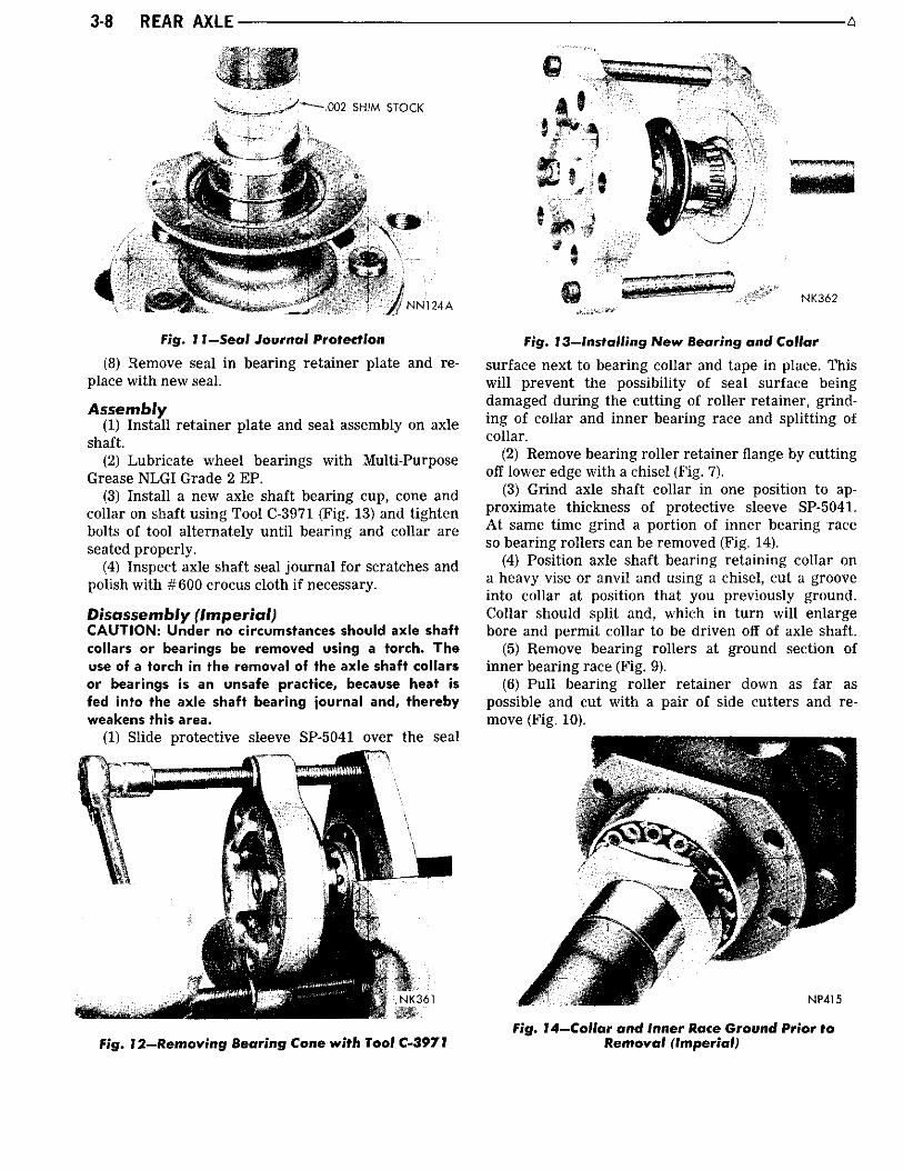
Fig. I 1 — Seal Journal Protection
(8) Remove seal i n bearing retainer plate and replace w i th new seal.
Assembly (1) Instal l retainer plate and seal assembly on axle
shaft. (2) Lubricate wheel bearings w i th Multi-Purpose
Grease NLGI Grade 2 EP. (3) Instal l a new axle shaft bearing cup, cone and
collar on shaft using Tool C-3971 (Fig. 13) and t ighten bolts of tool alternately u n t i l bearing and collar are seated properly.
(4) Inspect axle shaft seal j ourna l for scratches and polish w i th #600 crocus cloth i f necessary.
Disassembly (Imperial) CAUTION: Under no circumstances should axle shaft collars or bearings be removed using a torch. The use of a torch in the removal of the axle shaft collars or bearings is an unsafe practice, because heat is fed into the axle shaft bearing journal and, thereby weakens this area.
(1) Slide protective sleeve SP-5041 over the seal
Fig. 12—Removing Bearing Cone with Tool C-3971
Fig. 13—Installing New Bearing and Collar
surface next to bearing collar and tape in place. This w i l l prevent the possibility of seal surface being damaged dur ing the cutt ing of rol ler retainer, gr inding of collar and inner bearing race and spl i t t ing of collar.
(2) Remove bearing rol ler retainer flange by cutt ing off lower edge w i th a chisel (Fig. 7).
(3) Gr ind axle shaft collar i n one position to approximate thickness of protective sleeve SP-5041. A t same time gr ind a port ion of inner bearing race so bearing rollers can be removed (Fig. 14).
(4) Position axle shaft bearing retaining collar on a heavy vise or anvi l and using a chisel, cut a groove into collar at position that you previously ground. Collar should split and, which i n t u r n w i l l enlarge bore and permit collar to be driven off of axle shaft.
(5) Remove bearing rollers at ground section of inner bearing race (Fig. 9).
(6) Pu l l bearing rol ler retainer down as far as possible and cut w i th a pair of side cutters and remove (Fig. 10).
Fig. 14—Collar and Inner Race Ground Prior to Removal (Imperial)
A- •REAR AXLE 3-9
(7) Remove roller bearing cup and protective sleeve SP-5041 f rom axle shaft. CAUTION: Sleeve SP-5041 should not be used as a protector for the seal journal when pressing off the bearing cone, as it was not designed for this purpose.
(8) To avoid scuffing seal j ourna l when bearing cone is being removed, i t should be protected by a single wrap of .002 thickness shimstock held i n place by a rubber band (Fig. 11).
(9) Remove bearing cone using Tool C-3971 and adapter SP-5168. Tighten bolts of tool alternately u n t i l cone is removed (Fig. 12).
(10) Remove seal in bearing retainer plate and replace w i th new seal.
Assembly (Imperial) (1) Install retainer plate and seal assembly on axle
shaft. (2) Lubricate wheel bearings w i th Multi-Purpose
Grease NLGI Grade 2 E.P. or equivalent. (3) Instal l a new axle shaft bearing cup, cone on
axle shaft using Tool C-3971 and adapter SP-5168 (Fig. 13) and tighten bolts of tool alternately u n t i l bearing is seated properly. Repeat same step for instal l ing the collar.
(4) Inspect axle shaft seal j ourna l for scratches and polish wi th #600 crocus cloth i f necessary.
Installation (1) Clean axle housing flange face and brake sup
port plate thoroughly. Install a new rubber asbestos gasket on axle housing studs, followed by brake support plate assembly on left side of axle housing.
(2) Apply a th in coating of Multi-Purpose Grease, NLGI Grade 2 E.P. or equivalent to the outside diameter of the bearing cup pr ior to instal l ing i n the bearing bore. This operation is necessary as a corrosion preventative.
(3) Instal l foam gasket on the studs of axle housing and carefully slide axle shaft assembly through oi l seal and engage splines i n differential side gear.
(4) Tap end of axle shaft l i ght ly w i th a non-metallic mallet to position axle shaft bearing i n housing bearing bore. Position retainer plate over axle housing studs. Install retainer nuts and t ighten 30-35 foot-pounds. Start by t ightening bottom nut.
(5) Repeat step (1) for r ight side of axle housing. (6) Back off threaded adjuster of r i ght axle shaft
assembly un t i l inner face of adjuster is flush w i th inner face of retainer plate. Carefully slide axle shaft assembly through oi l seal and engage splines i n differential side gears.
(7) Repeat step (4).
AXLE SHAFT END PLAY
CAUTION: When setting axle shaft end play, both
rear wheels must be off the ground, otherwise a false end play setting will occur.
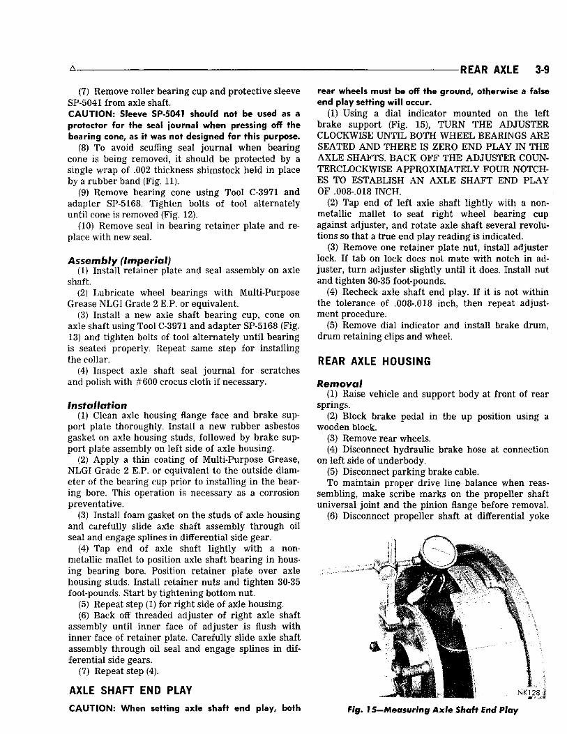
(1) Using a dia l indicator mounted on the left brake support (Fig. 15), TURN THE ADJUSTER CLOCKWISE UNT IL BOTH WHEEL BEARINGS ARE SEATED AND THERE IS ZERO END PLAY I N THE A X L E SHAFTS. BACK OFF THE ADJUSTER COUNTERCLOCKWISE APPROXIMATELY FOUR NOTCHES TO ESTABLISH A N AXLE SHAFT END PLAY OF .008-.018 INCH.
(2) Tap end of left axle shaft l ight ly w i th a non-metallic mallet to seat r ight wheel bearing cup against adjuster, and rotate axle shaft several revolutions so that a true end play reading is indicated.
(3) Remove one retainer plate nut, instal l adjuster lock. I f tab on lock does not mate w i th notch in adjuster, t u r n adjuster sl ightly u n t i l i t does. Install nut and t ighten 30-35 foot-pounds.
(4) Recheck axle shaft end play. I f i t is not w i th in the tolerance of .008-.018 inch, then repeat adjustment procedure.
(5) Remove dial indicator and instal l brake drum, d rum retaining clips and wheel.
REAR AXLE HOUSING
Removal (1) Raise vehicle and support body at front of rear
springs. (2) Block brake pedal i n the up position using a
wooden block. (3) Remove rear wheels. (4) Disconnect hydraulic brake hose at connection
on left side of underbody. (5) Disconnect parking brake cable. To maintain proper drive l ine balance when reas
sembling, make scribe marks on the propeller shaft universal jo int and the pinion flange before removal.
(6) Disconnect propeller shaft at differential yoke
N K 1 2 8
Fig. 15—Measuring Axle Shaft End Play
3-10 REAR AXLE A
and secure i n an upr ight position to prevent damage to f ront universal jo int .
(7) Remove shock absorber f rom spring plate studs and loosen rear spring " U " bolt nuts and remove " U " bolts.
(8) Remove the assembly f rom vehicle.
Installation (1) W i t h body of vehicle supported at f ront of rear
springs, position the rear axle assembly spring seats over the spring center bolts.
(2) Instal l spring " U " bolts and t ighten nuts to 45 foot-pounds and instal l shock absorbers on spring plate studs. (DO NOT OVER T IGHTEN " U " BOLT NUTS.)
(3) Instal l propeller shaft (match scribe marks on propeller shaft universal jo int and pinion flange). Tighten clamp screws to 15 foot-pounds.
(4) Connect parking brake cable. (5) Connect hydraulic brake hose, bleed and adjust
brakes. (6) Instal l rear wheels. (7) I f carrier was removed f rom axle housing dur
ing the removal operation, fill axle w i th proper amount and type of lubricant; see "Specifications" i n Lubricat ion section Group " 0 " .
Welding Rear Axle Housing The axle housing should be completely disassem
bled i f i t is to be welded w i th arc welding equipment. I t is also possible to weld the assembled housing w i th gas welding equipment, i f precaution is taken to protect gaskets and heat treated parts.
DIFFERENTIAL AND CARRIER
Removal (1) Remove flanged axle drive shafts. (2) Disconnect rear universal j o in t and support
propeller shaft up and out of the way to prevent damage to the f ront universal jo int .
(3) Remove the rear axle lubricant. (4) Loosen and remove the carrier-to-housing at
taching nuts and l i f t the carrier assembly f rom axle housing.
Disassembly Side play and runout check taken dur ing disassem
bly w i l l be very useful i n reassembly. (1) Mount carrier i n Stand DD-1014 and attach dial
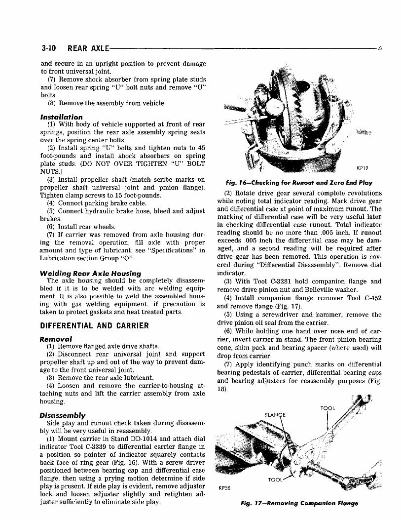
indicator Tool C-3339 to differential carrier flange i n a position so pointer of indicator squarely contacts back face of r ing gear (Fig. 16). W i t h a screw dr iver positioned between bearing cap and differential case flange, then using a pry ing motion determine i f side play is present. I f side play is evident, remove adjuster lock and loosen adjuster sl ightly and ret ighten adjuster sufficiently to eliminate side play.
j i t mm
• 1
KP19
Fig. 16—Checking for Runout and Zero End Play
(2) Rotate drive gear several complete revolutions while noting total indicator reading. Mark drive gear and differential case at point of max imum runout. The marking of differential case w i l l be very useful later i n checking differential case runout. Total indicator reading should be no more than .005 inch. I f runout exceeds .005 inch the differential case may be damaged, and a second reading w i l l be required after drive gear has been removed. This operation is covered dur ing "Dif ferential Disassembly". Remove dial indicator.
(3) W i t h Tool C-3281 hold companion flange and remove drive pinion nut and Belleville washer.
(4) Instal l companion flange remover Tool C-452 and remove flange (Fig. 17).
(5) Using a screwdriver and hammer, remove the drive pinion oi l seal f r om the carrier.
(6) While holding one hand over nose end of carr ier, invert carrier i n stand. The f ront pinion bearing cone, shim pack and bearing spacer (where used) w i l l drop f rom carrier.
(7) Apply identi fy ing punch marks on differential bearing pedestals of carrier, differential bearing caps and bearing adjusters for reassembly purposes (Fig. 18).
T O O L
T O O L "
K P 5 B
Fig. 17—Removing Compvmlcn friange

A REAR AXLE 3-11
Fig. 18—Marking Bearing Caps and Adjusters
(8) Remove both differential bearing adjuster lock screws and locks.
(9) W i th a 3/4 inch socket, loosen bearing cap bolts (one on each side) and back off bearing adjusters sl ightly using spanner wrench Tool C-406A; to remove differential bearing preload. Remove bearing cap bolts, caps and bearing adjusters.
(10) Remove differential and r ing gear assembly w i th bearing cups. Differential bearing cups must be kept w i th respective bearing cones.
(11) Remove drive pinion and rear bearing assembly f rom carrier.
Rear Pinion Bearing Removal (1) Remove drive pinion rear bearing f rom large
stem pinion wi th Tool C-293 and four (4) No. 37 plates (Fig. 19).
(2) Using a flat end brass dr i f t , remove f ront and rear pinion bearing cups.
DIFFERENTIAL CASE
Disassembly (1) Mount differential case and r ing gear assembly
Fig. 19—Removing Drive Pinion Rear Bearing
i n a vise equipped w i t h soft jaws (brass). (2) Remove drive gear bolts. BOLTS ARE LEFT
HAND THREAD. W i t h a non-metallic hammer, tap drive gear loose f r om differential case pi lot and remove.
(3) I f drive gear runout exceeded .005 inch i n step 2 (under "Carr ier Disassembly"), recheck the case as follows: Instal l dif ferential case and respective bearing cups i n carrier.
(4) Instal l bearing caps, cap bolts and bearing adjusters. Tighten bearing cap bolts down l ight ly and screw i n both adjusters w i th spanner wrench Tool C-406A.
(5) Tighten cap bolts and adjusters sufficiently to prevent any side play i n bearings.
(6) Attach a dial indicator Tool C-3339 to carrier flange so pointer of indicator squarely contacts drive gear surface of differential case flange between outer edge flange and drive gear bolt holes (Fig. 20).
(7) Rotate dif ferential case several complete revolutions while not ing total indicator reading. This reading must not exceed .003 inch runout. I f runout is i n excess of .003 inch, differential case must be replaced. In a case where the runout does not exceed .003 inch it is often possible to reduce the runout by positioning the drive gear 130° from point of maximum runout when reassembling drive gear on differential case.
(8) W i th a flat nose dr i f t and hammer, remove differential pinion shaft lock p in from back side of drive gear flange. (The hole is reamed only part way through, making i t necessary to remove lock p in f rom one direction.)
(9) W i th a brass dr i f t and hammer, remove differential pinion shaft and axle drive shaft thrust block.
(10) Rotate differential side gears u n t i l each differential pinion appears at large opening of case.
Fig. 20—Checking Drive Gear Mounting Flange Face Runout

3-12 REAR AXLE A
S H A F T
T H R U S T W A S H E R
B E A R I N G C O N E V
BEARING I I DIFFERENTIAL CASE
J
PIN
/ B E A R I N G C O N E
/ C U P
D R I V E G E A R
B O L T AND LOCK WASHER \
L O C K \
%^'J^^J I j A N D - P 1 N 1 G N
B E A R I N G C O N E C O L L A P S I B L E \
A D J U S T E R S P A C E R \ / CARRIER \
CAP j / \
S I D E G E A R \ \ W A S H E R
T H R U S T W A S H E R \ ^ T H R U S T B L O C K
i PINION THRUST WASHER BEARING C O N E
j S I D E G E A R
T H R U S T W A S H E R
FLANGE
SEAL \
y
WASHER
PLUG
^ - C A P
"—ADJUSTER
L O C K
BOLT AND LOCK WASHER
GUARD
W A S H E R
KP1D
Fig. 2 1 —Differential Carrier Assembly (Large Stem Tapered Pinion)
Remove each pinion and thrust washer at that t ime. (11) Remove both differential side gears and thrust
washers.
Cleaning and Inspection (Fig* 21J (1) Clean a l l parts i n a fast evaporating mineral
spirits or a dry cleaning solvent and w i th the except ion of bearings, dry w i th compressed air.
(2) Inspect differential bearing cones, cups and rollers for p i t t ing , spall ing or other visible damage. I f replacement is necessary, remove bearing cones f rom differential case w i th Tool C-293 and adapter plates No. 43 (Fig. 22).
(3) Inspect differential case for elongated or enlarged pinion shaft hole. The machined thrust washer surface areas and counterbores must be smooth and without metal deposits or surface imperfections. I f any of the above conditions exist, satisfactory correction must be made or the case replaced. Inspect case for cracks or other visible damage which might render i t unfit for fur ther service.
(4) Inspect dif ferential p inion shaft for excessive wear i n contact area of differential pinions. Shaft should be smooth and round w i th no scoring or metal pickup.
(5) Inspect dif ferential side gears and pinions, they should have smooth teeth w i th a un i fo rm contact patte rn without excessive wear or broken surfaces. The differential side gear and pinion thrust washers should be smooth and free f rom any scoring or metal pickup.
(6) Inspect axle shaft thrust block for excessive wear or visible damage. The wear surface on the opposite ends of the blocks, must be smooth.
(7) Inspect dif ferential pinion shaft lock p in for
damage or looseness i n case. Replace p in or case as necessary.
(8) Inspect drive gear and pinion for worn or chipped teeth or damaged attaching bolt threads. I f replacement is necessary, replace both the drive gear and drive pinion as they are available i n matched sets only.
(9) Inspect drive pinion bearing cones, cups and rollers for pi t t ing, spalling, excessive wear, or other
v n s c c o o
KP8
Fig, 22—Removing lOif^erentM Bearings

-REAR AXLE 3-13
visible damage. I f inspection reveals that either are unfit for further service, replace both cup and cone.
(10) Inspect differential carrier for cracks or other visible damage which would render i t unfit for further service. Raised metal on the shoulder of bearing cup bores incurred i n removing pinion cups should be flattened by use of a flat nose punch.
(11) Inspect drive pinion for damaged bearing journals and mounting shim surface or excessively worn splines. I f replacement is necessary, replace both the drive pinion and drive gear as they are available in matched sets only.
(12) Inspect companion flange for cracks, worn splines, pitted, rough or corroded oi l seal contacting surface. Repair or replace companion flange as necessary.
ASSEMBLY
LUBRICATE A L L PARTS BEFORE ASSEMBLY WITH LUBRICANT AS SPECIF IED IN (LUBRICATION GROUP "O")
(1) Install thrust washers on differential side gears and position gears in case.
(2) Place thrust washers on both differential pinions and through large window of differential case, mesh the pinion gears w i th the side gears, having pinions exactly 180 degrees opposite each other.
(3) Rotate side gears 90 degrees to align pinions and thrust washers w i th differential pinion shaft holes in case.
(4) From pinion shaft lock p in hole side of case, insert slotted end of pinion shaft through case, and the conical thrust washer, and just through one of the pinion gears.
(5) Install thrust block through side gear hub, so that slot is centered between the side gears.
(6) While keeping al l of these parts i n proper alignment, push pinion shaft into case u n t i l locking pin hole in pinion shaft is i n exact alignment w i th its respective hole in case. Instal l pinion shaft lock p in through hole i n case f rom pinion shaft side of drive gear flange. The contacting surfaces of the drive gear and differential case flange must be clean and free of all burrs.
(7) Using an Arkansas stone, relieve the sharp edge of the chamfer on the inside diameter of the r ing gear (Fig. 23). This is very important otherwise during the installation of ring gear on differential case, the sharp edge will remove metal from the pilot diameter of case and can get imbedded between differential case flange and gear; causing gear not to seat properly.
(8) Position drive gear on differential case pilot, aligning threaded holes of drive gear w i t h those i n differential case flange.
(9) Insert drive gear screws (LEFT HAND THREADS) through case flange and into drive gear.
NU403
Fig. 23—Stoning Chamfer on Ring Gear
After a l l cap screws are properly started, tap drive gear against differential case flange w i t h a non-metallic mallet.
(10) Position uni t between brass jaws of a vise and alternately t ighten each cap screw to 55 foot-pounds.
(11) Position each differential bearing cone on hub of dif ferential case (taper away f rom drive gear) and w i th instal l ing Tool C-4086 install bearing cones. A n arbor press may be used i n conjunction w i t h i n stall ing tool. CAUTION: Never exert pressure against the bearing cage, since this would damage the bearing.
PINION BEARING CUP INSTALLATION
(1) Position pinion bearing cups squarely i n bores of carrier. Assemble Tool C-758-D4 (Fig. 24) by placing spacer SP-5387 followed by rear pinion bearing cone over main screw of tool and inserting i t into carrier f rom gear side.
(2) Place f ront pinion bearing cone over main
G A U G E B L O C K SP-528 O R SP-3250 8 3 / 4 " v> A N D 9 % " A X L E
W R E N C H A % C R O S S B O R E A R B O R mf r \ V SP~561
8 % " A X L E •» 1 V x ^ SP-5183 9 % " A X L E
c r V w S P A C E R \ SCREW W A S H E R ' \ SP-538
S L E E V E SP-2920
4 SLEEVE SP-1370
SPACER ^ W A S H E R
SP-1371
C O M P R E S S I O N S L E E V E SP-535
S P A C E R W A S H E R
SP-2921 O R 5 3 8 7 8 3 / 4 " A X L E
SP-5184 9 3 / 4 " A X L E
T S L E E V E S P A C E R
'SP-1682 S P " 1 7 3 0
SP-3639
C E N T R A L I Z I N G W A S H E R y& SP-534 Jj?
P I N I O N — C O M P R E S S I O N L O C A T I N G T N U T SP-533 S P A C E R S P A C E R SP-2919 SP-539 N U 4 1 8 A
Fig. 24—Rear Axle Setting Gauge Tool C-758-D4

3-14 REAR AXLE • — » —
screw of tool followed by compression sleeve SP-535, centralizing washer SP-534, and main screw nut SP-533. Hold compression sleeve w i th the companion flange holding Tool C-3281 and t ighten nut (Fig. 25) allowing tool to rotate as nut is being tightened in order not to br inne l bearing cone or cups. Do not remove tool after installing cups.
PINION BEARING PRELOAD AND DEPTH OF MESH SETTING USING TOOL C-758-D4
The 8-3/4" large stem differential and carrier assembly has incorporated a collapsible spacer which bears against the inner races of the f ront and rear bearings. This collapsible spacer is used to establish pinion bearing preload. The large stem pinion requires the depth of mesh adjustment first while pinion bearing preload is the last operation performed.
The position of the drive pinion w i th respect to the drive gear (depth of mesh) is determined by the locat ion of the bearing cup shoulders i n the carrier and by the port ion of the p in ion i n back of the rear bearing. The thickness of the rear pinion bearing mounting shim suitable for the carrier can be determined by using Tool C-758-D4.
DEPTH OF MESH (Large Stem Pinion)
Inspect differential bearing cups and cones, carrier for gr i t and d i r t or other foreign material. Clean ai l parts in fast evaporating mineral spirits or a dry cleaning solvent and w i th the exception of bearing cones, dry w i th compressed air. Front Pinion Bearing Cone and Cup Must Never Be Reused Under Any Circumstances.
(1) Assemble spacer SP-5387 to main section of tool followed by spacer SP-1730. Instal l rear p inion bearing cone over spacer SP-1730 and against spacer SP-5387 (Fig. 26).
(2) Insert assembly into carrier and instal l f ront pinion bearing cone over tool shaft and i n its proper
ft iP^
far' KP13B
Fig. 25—Seating Bearing Cup in Carrier Housing
A
SP-561 PINION LOCATING WASHER
NY168C
Fig. 26-Tool C-758-D4 Installed in Housing (8-3/4 Large Stem Pinion)
position i n bearing cup. Instal l tool spacer, tool thrust washer and tool nut on shaft.
(3) W i th nose of carrier up, place flange holding Tool C-3281 on compression sleeve. Al low assembly to rotate while t ightening nut to not more than 25-50 foot-pounds. Always make sure bearing cones are lubricated with hypoid gear lubricant.
(4) Tu rn tool several complete revolutions i n both directions to permit bearing rol lers to seat. Af ter bearing rollers are properly seated, check bearing preload by rotat ing tool w i th an inch-pound torque wrench. The correct bearing preload should be f rom 20-30 inch-pounds for new bearings.
(5) W i t h proper bearing preload set, invert carrier i n stand and instal l gauge block SP-528 or SP-3250 to the main screw attaching i t w i th A l l en screw securely (Fig. 27). The flat port ion of gauge block should be facing differential bearing pedestals.
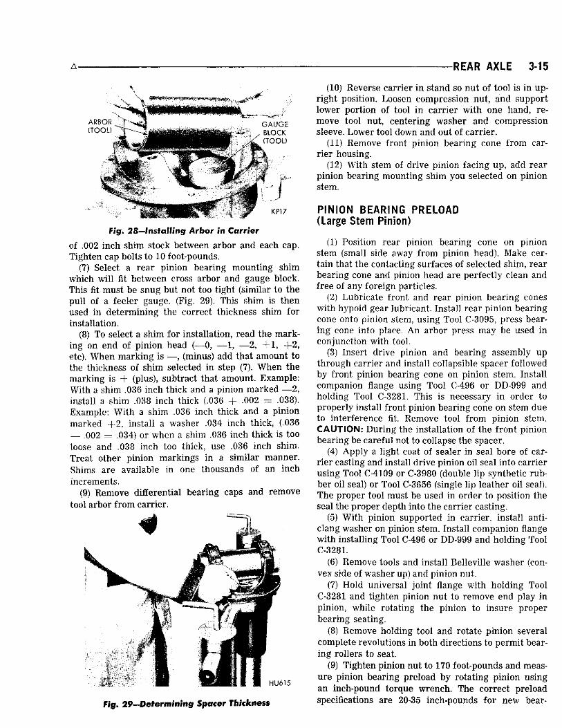
(6) Position tool arbor SP-561 in differential bearing pedestals of carrier (Fig. 28). Center the arbor so that an approximate equal distance is maintained at both ends. Position differential bearing caps and attaching bolts on carrier pedestals, and insert a piece
Fig. 27—Installing Gauge Blo<sk on fool
A REAR AXLE 3-15
rig. 28—Installing Arbor in Carrier
of .002 inch shim stock between arbor and each cap. Tighten cap bolts to 10 foot-pounds.
(7) Select a rear pinion bearing mounting shim which w i l l fit between cross arbor and gauge block. This fit must be snug but not too t ight (similar to the pu l l of a feeler gauge. (Fig. 29). This shim is then used i n determining the correct thickness shim for installation.
(8) To select a shim for installation, read the marking on end of pinion head (—0, — 1 , — 2 , + 1 , + 2 , etc). When marking is —, (minus) add that amount to the thickness of shim selected i n step (7). When the marking is + (plus), subtract that amount. Example: With a shim .036 inch thick and a pinion marked — 2 , install a shim .038 inch thick (.036 + .002 = .038). Example: W i t h a shim .036 inch thick and a pinion marked + 2 , install a washer .034 inch thick, (.036 — .002 = .034) or when a shim .036 inch thick is too loose and .038 inch too thick, use .036 inch shim. Treat other pinion markings i n a similar manner. Shims are available in one thousands of an inch increments.
(9) Remove differential bearing caps and remove tool arbor f rom carrier.
fig. 29—Determining Spacer Thickness
(10) Reverse carrier i n stand so nut of tool is i n upr ight position. Loosen compression nut, and support lower port ion of tool i n carrier w i t h one hand, remove tool nut, centering washer and compression sleeve. Lower tool down and out of carrier.
(11) Remove front pinion bearing cone f rom carr ier housing.
(12) With stem of drive pinion facing up, add rear pinion bearing mounting shim you selected on pinion stem.
PINION BEARING PRELOAD (Large Stem Pinion)
(1) Position rear pinion bearing cone on pinion stem (small side away f rom pinion head). Make certain that the contacting surfaces of selected shim, rear bearing cone and pinion head are perfectly clean and free of any foreign particles.
(2) Lubricate front and rear pinion bearing cones w i th hypoid gear lubricant. Instal l rear pinion bearing cone onto pinion stem, using Tool C-3095, press bearing cone into place. An arbor press may be used i n conjunction wi th tool.
(3) Insert drive pinion and bearing assembly up through carrier and install collapsible spacer followed by front pinion bearing cone on pinion stem. Install companion flange using Tool C-496 or DD-999 and holding Tool C-3281. This is necessary in order to properly install front pinion bearing cone on stem due to interference fit. Remove tool f rom pinion stem. CAUTION: Dur ing the installation of the f ront pinion bearing be careful not to collapse the spacer.
(4) Apply a l ight coat of sealer in seal bore of carr ier casting and install drive pinion oi l seal into carrier using Tool C-4109 or C-3980 (double l ip synthetic rubber oi l seal) or Tool C-3656 (single l ip leather oi l seal). The proper tool must be used in order to position the seal the proper depth into the carrier casting.
(5) W i th pinion supported i n carrier, instal l anti-clang washer on pinion stem. Instal l companion flange w i th instal l ing Tool C-496 or DD-999 and holding Tool C-3281.
(6) Remove tools and instal l Belleville washer (convex side of washer up) and pinion nut.
(7) Hold universal jo int flange w i th holding Tool C-3281 and tighten pinion nut to remove end play i n pinion, while rotating the pinion to insure proper bearing seating.
(8) Remove holding tool and rotate pinion several complete revolutions in both directions to permit bearing rollers to seat.
(9) Tighten pinion nut to 170 foot-pounds and measure pinion bearing preload by rotating pinion using an inch-pound torque wrench. The correct preload specifications are 20-35 inch-pounds for new bear-
3-16 REAR AXLE
ings or 10 inch-pounds over the original i f the old rear pinion bearing is being reused. Correct bearing preload readings can only be obtained w i th nose of carrier i n upr ight position. Continue t ightening of pinion nut in small increments and checking pinion bearing preload un t i l proper preload is obtained. Bearing preload should be uni form dur ing complete revolution. A preload reading that varies dur ing rotation indicates a binding condition which has to be corrected. The assembly is unacceptable i f final pinion nut torque is below 170 foot-pounds or pinion bearing preload is not w i th in the correct specifications. NOTE: UNDER NO CIRCUMSTANCES SHOULD THE PINION NUT BE BACKED OFF TO LESSEN PRELOAD. IF THIS IS DONE A NEW COLLAPSIBLE SPACER MUST BE INSTALLED AND NUT RE-TIGHTENED UNT IL PROPER PRELOAD IS OBTAINED.
DEPTH OF MESH (Without Using Tool C-758-D4)
I f the differential assembly was satisfactorily quiet before being disassembled, the drive pinion must be assembled w i th new pinion bearings. I f replacement parts are installed, a complete readjustment is necessary; the proper thickness shim must be selected and installed. The drive gear and pinion are manufactured and lapped in matching sets and are available in matched sets only. The adjustment position in which the best tooth contact is obtained is marked on the end of the pinion head.
To obtain the proper pinion setting i n relat ion to the drive gear, the correct thickness mounting shim must be selected before the drive pinion is installed i n the carrier. The pin ion bearing mount ing shims are available in one thousands increments f r om .020-.038 inch. To select the proper thickness shim, proceed as follows: I t w i l l be noted that the head of the drive pinion is marked w i th a plus ( + ) or minus (—) sign followed by a number ranging f rom 1 to 4, or zero (0) marking.
I f the old and new pinion have the same marking and i f the original bearing is being reused, use a mount ing shim of the same thickness. But i f the old pinion is marked zero (0) and the new pinion is marked + 2 , t r y a .002 inch thinner shim. I f the new pinion is marked — 2 , t r y a .002 inch thicker shim.
Pinion Bearing Preload (Large Stem) After selecting the correct pinion bearing mounting
shim and instal l ing i t behind the rear pinion bearing cone proceed as follows: Instal l the pinion assembly into the carrier. Instal l the new collapsible spacer followed by new front pinion bearing cone on pinion stem. Press f ront pinion bearing cone on pinion stem,
- A
being careful not to collapse the spacer. Apply a l ight coat of sealer to drive pinion o i l seal
and carrier casting bore and install drive pinion oi l seal w i th Tool C-4109 or C-3980 (synthetic rubber seal or Tool C-3656 (leather seal). Install anti-clang washer and universal jo int flange, Belleville washer (convex side of washer up) and nut. Tighten the pinion nut to 170 foot-pounds and using an inch-pounds torque wrench rotate the pinion to determine preload. The correct preload specifications are 20-30 inch-pounds for new bearings or 10 inch-pounds over the original i f the old rear pinion bearing is being reused. I f preload is not correct, continue to tighten pinion nut in small increments and checking preload un t i l preload on pinion bearings is correct. A min imum of 170 footpounds of torque is required on pinion nut. Under no circumstances should the pinion nut be backed off to lessen preload. If this is done a new pinion bearing collapsible spacer must be installed and nut retight-ened until proper preload is obtained.
Installation of Differential and Ring Gear in Carrier
(1) Holding differential and r ing gear assembly w i th bearing cups on respective bearing cones, carefu l ly instal l the assembly into carrier.
(2) Instal l differential bearing caps, on respective sides, making certain that identification marks on caps correspond w i th those on carrier. Instal l cap bolts and t ighten bolts of each cap by hand.
(3) Instal l differential bearing adjusters, on respect ive sides, making certain that identification marks correspond. Screw adjuster i n by hand. No attempt should be made to apply any excessive pressure at this t ime.
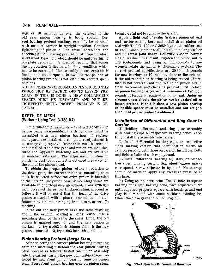
(4) Using spanner wrenches Tool C-406A to square bearing cups w i th bearing cone, t u r n adjusters " I N " u n t i l cups are properly square w i th bearings and end play is eliminated w i t h some backlash existing between the drive gear and pinion (Fig. 30).
KP20A
Fig. 30—Adjusting Differential Bearings

-REAR AXLE 3-17
(5) Tighten one differential bearing cap bolt on each side to 85-90 foot-pounds.
DRIVE GEAR AND PINION BACKLASH
Correct drive gear and pinion backlash when properly set is .006 to .008 inch at point of m i n i m u m backlash. Rotate drive pinion and r ing gear several revolutions in both directions in order to seat the bearing rollers. This is necessary before setting backlash.
(1) Attach a dial indicator Tool C-3339 to carrier flange so pointer of indicator is squarely contacting one drive gear tooth (drive side) (Fig. 31).
(2) Measure backlash between drive gear and pinion at four positions, approximately 90 degrees apart. A f ter point of least backlash has been determined, mark drive gear. Do not rotate drive gear from point of least backlash until all adjustments have been completed.
(3) Using Tool C-406A (spanner wrench) t u r n both bearing adjusters equally (in same direction) u n t i l backlash between drive gear and pinion is .0005 to .0015 inch. This backlash variation is given to permit alignment and installation of the bearing adjuster lock, lockwasher and attaching screw. The adjuster must only be turned in a clockwise direction and under no circumstances should be backed off.
(4) Instal l adjuster lock on bearing cap, back-face side of drive gear. Tighten lock screw to 15 to 20 foot-pounds.
Differential Bearing Preload (1) Tu rn bearing adjuster (tooth side of drive gear)
(Fig. 32) i n a notch at a time (notch referred to is the adjuster lock holes) un t i l backlash between drive gear and pinion is a min imum of .006 to .008 inch. This w i l l preload differential bearings and establish correct backlash.
P A T T E R N C L O S E TO C E N T E R
KP21
HEEL END-Da , y z S I D E (CONVEX)
HEEL E N D — C O A S T
S I D E ( C O N C A V E / N R ] ° 8
Fig. 31—Measuring Backlash between Drive Gear and Pinion
Fig. 32—Desired Tooth Contact Under Light Load
(2) Tighten the remaining two differential bearing cap bolts to 85-90 foot-pounds.
(3) Instal l remaining adjuster lock, lockwasher and attaching screw. Tighten to 15-20 foot-pounds.
GEAR TOOTH CONTACT PATTERN
The gear tooth contact pattern w i l l disclose whether the correct rear pinion bearing mounting shim has been installed and the drive gear backlash set properly. Backlash between the drive gear and pinion must be maintained w i th in the specified l imits u n t i l correct tooth contact pattern is obtained.
(1) Apply a th in f i lm of red or white lead on both the drive and coast side of the drive gear teeth. Rotate drive gear one complete revolution in both directions while load is being applied w i th a round bar or screwdriver between the carrier casting and different ia l case flange. This action w i l l leave a distinct contact pattern on both the drive and coast side of the drive gear teeth.
(2) Observe the contact pattern on the drive gear teeth and compare w i th those in figures 32, 33 and 35 to determine i f pattern is properly located. W i th pinion depth of mesh and gear backlash set properly, your contact pattern should resemble that in (Fig. 32). Notice that the correct contact pattern is wel l centered on both drive and coast sides of the teeth. When tooth contact patterns are obtained by hand, they are apt to be rather small. Under the actual operating load, however, the contact area increases.
(3) I f after observing the contact pattern you find i t resembles that in (Fig. 33), the drive pinion is too far away f rom centerline of the r ing gear, the contact pattern w i l l appear high on the heel on drive side and high on toe on coast side. To correct this type tooth contact pattern, increase the thickness of the rear pinion bearing mounting spacer (Fig. 34), which w i l l cause the high heel contact on drive side to lower and move toward the toe; the high toe contact on coast side w i l l lower and move toward the heel.

3-18 REAR AXLE- - A
THICKER S P A C E R N E E D E D
. 4 . ' • • rV.W
HEEL END-DRIVE SIDE (CONVEX) "*
HEEL E N D - C O A S T SIDE (CONCAVE) N R 1 "
Fig. 33—incorrect Tooth Contact Pattern (Increase Spacer Thickness)
(4) I f after observing the contact pattern you find i t resembles that i n (Fig. 35), the drive pinion is too close to the r i ng gear, the pattern w i l l appear low on the toe on drive side and low heel contact on coast side. To correct this type tooth contact pattern, decrease the thickness of the rear pinion bearing mounting spacer (Fig. 36), which w i l l cause the low toe contact on drive side to raise and move toward the heel; low heel contact on coast side w i l l raise and move toward the toe.
DIFFERENTIAL AND CARRIER
Installation (1) Thoroughly clean the gasket surfaces of the car
r ier and rear axle housing. (2) Using a new gasket, instal l the carrier assembly
into the axle housing. Tighten the carrier to axle housing nuts to 45 foot-pounds.
(3) Refer to " Instal lat ion of Rear Axle Shaft," when instal l ing and setting axle shaft end play.
(4) Instal l propeller shaft (match scribe marks on propeller shaft universal j o in t and pinion flange). Tighten clamp screws to 15 foot-pounds.
(5) Remove wooden block f rom under brake pedal and bleed and adjust brakes.
PATTERN MOVES TOWARD CENTER AND DOWN
/ - TOE / ~ \
(6) Instal l rear wheels and tighten to 65 footpounds.
LUBRICATION
Refill axle assembly w i th Multipurpose Gear Lubr i cant, as defined by MIL-L-2105B (API GL-5) should be used in al l rear axles w i th conventional differentials; Chrysler Hypoid Lubricant part number 2933565 is an oi l of this type and is recommended or an equivalent be used.
In Sure-Grip axles on all 1970 Vehicles i t is recommended that only Chrysler Hypoid Lubricant part number 2933565 or an equivalent be used. This lubr i cant, recommended for conventional differentials too, contains special additives to provide proper different ia l durabi l i ty and performance. Anticipated Temperature Range Viscosity Grade
Above — 10°F. SAE 90 As low as — 30°F. SAE 80 Bleow — 3 0 ° F . SAE 75
REMOVAL AND REPLACEMENT OF DRIVE PINION FLANGE AND OIL SEAL IN VEHICLE
On large stem carriers which use the collapsible spacer to obtain pinion bearing preload, the fol lowing procedure for the removal and replacement of the drive pinion flange and pinion oi l seal must be followed to assure that the proper bearing preload is maintained in the axle assembly. I f this procedure is not followed i t could result in a premature fai lure of the axle.
(1) Raise vehicle on hoist and make scribe marks on propeller shaft universal jo int , drive pinion flange and end of pinion stem.
(2) Disconnect propeller shaft at pinion flange and secure i n an upr ight position to prevent damage to front universal jo int .
(3) Remove the rear wheels and brake drums to prevent any drag or a possible false preload reading could occur.
THINNER SPACER NEEDED
•N^-COAST DE (CONCAVE) N R 2 0 0
HEEL E N D - D R I V E SIDE (CONVEX)
^jgaEND-COAST SIDE iCONCAVEi NR201
Fig. 34—Effect on Tooth Contact Pattern as Spacer Thickness is Increased
Fig. 35—Incorrect Tooth Contact Pattern (Decrease Spacer Thickness)

A REAR AXLE 3-19
(4) Using inch-pound torque wrench C-685 measure pinion bearing preload by rotat ing p in ion w i t h handle of wrench floating, read the torque whi le wrench is moving through several complete revolutions and record. This operation Is very Important because preload must be carefully reset when reassembling.
(5) W i th Tool C-3281 hold companion flange and remove drive pinion nut and Belleville washer.
(6) Install companion flange remover Tool C-452 and remove flange. Lower rear of vehicle to prevent lubricant leakage.
(7) Using a screwdriver and hammer, remove the pinion oil seal f rom the carrier and clean the oil seal seat.
(8) Check splines on pinion shaft stem to be sure they are free of burrs or are not worn badly. I f burrs are evident remove them using crocus cloth by working in a rotational motion. Wipe the pinion shaft clean.
(9) Inspect companion flange for cracks, worn splines, pitted, rough or corroded oi l seal contacting surface. Repair or replace companion flange as necessary.
(10) Apply a l ight coat of sealer i n seal bore of carr ier and install drive pinion oi l seal into carrier using Tool C-4109 or C-3980 (Double l ip synthetic rubber oi l seal) or Tool C-3656 (single l ip leather oi l seal). The proper tool must be used i n order to properly position the seal the correct depth into the carrier casting.
(11) Position companion flange on pinion stem being careful to match scribe marks made previously before removal.
(12) Install companion flange w i th instal l ing Tool C-496 or DD-999 and holding Tool C-3281.
(13) Remove tool and instal l Belleville washer (convex side of washer up) and pinion nut.
(14) Hold universal jo int flange w i th holding Tool C-3281 and tighten pinion nut to 170 foot-pounds. Rotate pinion several complete revolutions to assure that bearing rollers are properly seated. Using an inch-pound torque wrench C-685 measure pinion bearing preload. Continue t ightening pinion nut and
P A T T E R N M O V E S INWARD AND U P
HEEL E N D — D R I V E S I D E ( C O N V E X )
'-:EEL END- COAST S I D E ( C O N C A V E ) NR202
Fig. 36—Effect on Tooth Contact Pattern as Spacer Thickness is Decreased
checking preload un t i l preload is at the original established setting you found in step 4. Under no circumstances should the preload be more than 5 inch-pounds over the established setting found at time of checking i n step 4 of procedure.
Bearing preload should be uni form dur ing a complete revolution. A preload reading that varies dur ing rotation indicates a binding condition which has to be corrected. The assembly is unacceptable i f final pinion nut torque is below 170 foot-pounds or pinion bearing preload is not w i th in the correct specifications. CAUTION: Never back off the pinion nut to lessen pinion bearing preload. If the desired preload is exceeded a new collapsible spacer must be installed and nut retightened until proper preload is obtained. In addition, the universal joint flange must never be hammered on, or power tools used.
(15) Instal l propeller shaft (match scribe marks on propeller shaft universal point and pinion flange). Tighten clamp screws to 15 foot-pounds.
(16) Instal l the rear brake drums and wheels and tighten nuts 65 foot-pounds.
(17) Raise the vehicle to a level position so axle assembly is at correct running position and check lubr i cant level. Add the correct type of lubricant required to br ing lubricant to proper level.
SURE-GRIP DIFFERENTIAL
INDEX Page
Installing Sure Grip Differential and Carrier Assembly 22
Lubrication 22 Sure Grip Differential Identification . . . . . 20 Sure Grip Differential Noise . . . . . . . . . . . . . . . . . . . . 20
Page Sure Grip Differential 21
Removal 22 Cleaning & Inspection 22 Assembly . . . . . . 22
Testing Sure Grip Differential 21
GENERAL INFORMATION
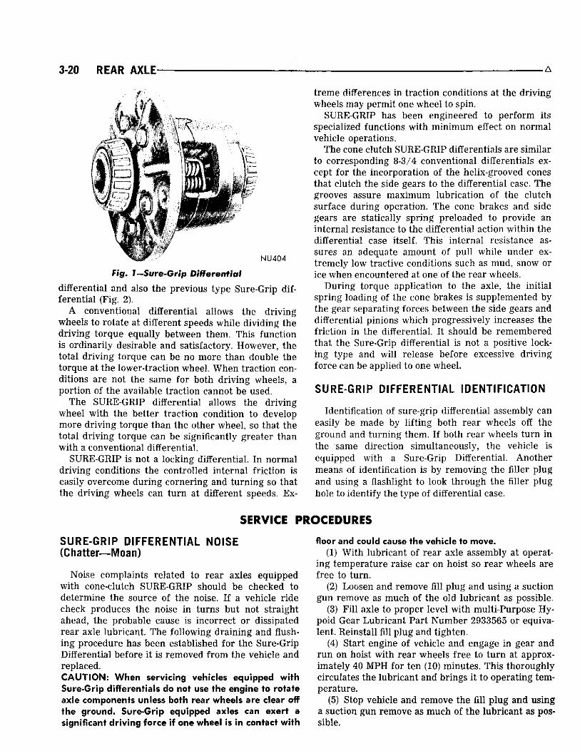
A new Sure-Grip differential being offered as a special equipment option i n the 8-3/4" rear axles (Fig. 1).
The Sure-Grip differential design is basic and simple and consists of a two piece case construction and is completely interchangeable w i th the conventional
3-20 REAR AXLE' A
*' NU404
Fig. 1—Sure-Grip Differential
differential and also the previous type Sure-Grip differential (Fig. 2).
A conventional differential allows the dr iv ing wheels to rotate at different speeds while div iding the dr iv ing torque equally between them. This function is ordinari ly desirable and satisfactory. However, the total dr iv ing torque can be no more than double the torque at the lower-traction wheel. When traction conditions are not the same for both dr iv ing wheels, a port ion of the available traction cannot be used.
The SURE-GRIP differential allows the dr iv ing wheel w i th the better tract ion condition to develop more dr iv ing torque than the other wheel, so that the total dr iv ing torque can be significantly greater than w i th a conventional differential.
SURE-GRIP is not a locking differential. I n normal dr iv ing conditions the controlled internal f r ic t ion is easily overcome dur ing cornering and turn ing so that the dr iv ing wheels can t u r n at different speeds. Ex
treme differences in tract ion conditions at the dr iv ing wheels may permit one wheel to spin.
SURE-GRIP has been engineered to per form its specialized functions w i th min imum effect on normal vehicle operations.
The cone clutch SURE-GRIP differentials are similar to corresponding 8-3/4 conventional differentials except for the incorporation of the helix-grooved cones that clutch the side gears to the differential case. The grooves assure maximum lubrication of the clutch surface dur ing operation. The cone brakes and side gears are statically spring preloaded to provide an internal resistance to the differential action w i th in the differential case itself. This internal resistance assures an adequate amount of pu l l while under extremely low tractive conditions such as mud, snow or ice when encountered at one of the rear wheels.
Dur ing torque application to the axle, the in i t ia l spring loading of the cone brakes is supplemented by the gear separating forces between the side gears and differential pinions which progressively increases the fr ict ion in the differential. I t should be remembered that the Sure-Grip differential is not a positive locking type and w i l l release before excessive dr iv ing force can be applied to one wheel.
SURE-GRIP DIFFERENTIAL IDENTIFICATION
Identification of sure-grip differential assembly can easily be made by l i f t ing both rear wheels off the ground and turn ing them. I f both rear wheels t u r n i n the same direction simultaneously, the vehicle is equipped w i th a Sure-Grip Differential. Another means of identification is by removing the fil ler p lug and using a flashlight to look through the filler plug hole to identify the type of differential case.
SERVICE PROCEDURES
SURE-GRIP DIFFERENTIAL NOISE (Chatter—Moan)
Noise complaints related to rear axles equipped w i th cone-clutch SURE-GRIP should be checked to determine the source of the noise. I f a vehicle r ide check produces the noise i n turns but not straight ahead, the probable cause is incorrect or dissipated rear axle lubricant. The fol lowing dra ining and flushing procedure has been established for the Sure-Grip Differential before i t is removed f rom the vehicle and replaced. CAUTION: When servicing vehicles equipped with Sure-Grip differentials do not use the engine to rotate axle components unless both rear wheels are clear off the ground. Sure-Grip equipped axles can exert a significant driving force if one wheel is in contact with
floor and could cause the vehicle to move. (1) W i th lubricant of rear axle assembly at operat
ing temperature raise car on hoist so rear wheels are free to turn .
(2) Loosen and remove fill p lug and using a suction gun remove as much of the old lubricant as possible.
(3) F i l l axle to proper level w i th multi-Purpose Hypoid Gear Lubricant Part Number 2933565 or equivalent. Reinstall fill p lug and t ighten.
(4) Start engine of vehicle and engage in gear and r u n on hoist w i th rear wheels free to t u r n at approximately 40 MPH for ten (10) minutes. This thoroughly circulates the lubricant and brings i t to operating temperature.
(5) Stop vehicle and remove the fill p lug and using a suction gun remove as much of the lubricant as possible.
REAR AXLE 3-21
DIFFERENTIAL CASE
PINIONS
COIL SPRING
SIDE GEARS
CONE CLUTCH
LUBRICATION POCKET LUBRICATION
GROOVES
NU405
Fig. 2-Sme-Grip Differential (Schematic)
(6) Refill axle to proper level w i t h multi-Purpose Hypoid Gear Lubricant Part Number 2933565 or equivalent. Reinstall fill p lug and tighten.
(7) Lower vehicle on hoist and re turn to customer to drive and evaluate for approximately 100 miles to determine i f lubricant corrects the noise complaint.
I f after the vehicle is driven approximately 100 miles and the noise condition is s t i l l evident, remove the differential and carrier assembly and replace the Sure-Grip Differential. The Sure-Grip Differential and the internal parts are serviced as an assembly only.
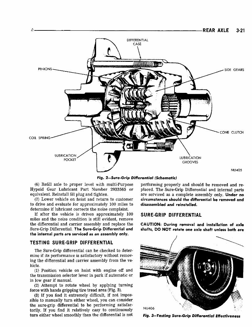
TESTING SURE-GRIP DIFFERENTIAL
The Sure-Grip differential can be checked to determine i f its performance is satisfactory without removing the differential and carrier assembly f rom the vehicle.
(1) Position vehicle on hoist w i th engine off and the transmission selector lever i n park i f automatic or in low gear i f manual.
(2) At tempt to rotate wheel by applying turn ing force w i th hands gr ipping t i re tread area (Fig. 3).
(3) I f you find i t extremely difficult, i f not impossible to manually t u r n either wheel, you can consider the sure-grip differential to be performing satisfactor i ly . I f you find i t relatively easy to continuously t u r n either wheel smoothly then the differential is not
performing properly and should be removed and replaced. The Sure-Grip Differential and internal parts are serviced as a complete assembly only. Under no circumstances should the differential be removed and disassembled and reinstalled.
SURE-GRIP DIFFERENTIAL
CAUTION: During removal and installation of axle shafts, DO NOT rotate one axle shaft unless both are
NU406
Fig. 3—Testing Sure-Grip Differential Effectiveness

3-22 REAR AXLE
in position. Rotation of one axle shaft without the other in place may result in misalignment of the two spline segments with which the axle shaft spline engages, and will necessitate difficult realignment procedures when shaft is installed.
Removal Follow the same procedure outl ined under conven
tional differential removal.
Cleaning and Inspection (1) Clean the Sure-Grip differential assembly i n a
fast evaporating mineral spirits or a dry cleaning solvent and w i th exception of bearings, dry w i th compressed air.
(2) Inspect differential bearing cones, cups and ro l l ers for p i t t ing , spall ing or other visible damage. I f replacement is necessary, remove bearing cones f r om differential case using Tool C-293 and adapter plates No. 43.
(3) Visually inspect differential case for cracks or other visible damage which might render i t unfit for further service.
Assembly I f dur ing cleaning and inspection the differential
bearings were found to be unfit for further use and were removed fol low this procedure for installation of new bearings.
(1) Position each differential bearing cone on hub of differential case (taper away f rom drive gear) and w i th instal l ing Tool C-4086, instal l bearing cones. A n arbor press may be used in conjunction w i th instal l ing tool. CAUTION: Never exert pressure against the bearing cage, since this would damage the bearing.
(2) I f the r ing gear was removed f rom the sure-grip differential case or is being replaced w i th a new r i n g gear for any reason, new nylok drive gear screws must be installed. IMPORTANT: The procedure for instal l ing the r i n g gear on differential case must be followed so the r i n g gear seats on the differential case properly.
(3) Using an Arkansas stone, relieve the sharp edge of the chamfer on the inside diameter of the r i n g gear (Fig. 23 i n 8-3/4" Axle section of this group). This is very important, otherwise dur ing the installat ion of r ing gear on differential case, the sharp edge
A
w i l l remove metal f rom the pi lot diameter of case and can get imbedded between differential case flange and gear; causing gear not to seat properly.
(4) Position r ing gear on differential case pilot al igning threaded holes of r ing gear w i th those in differential case flange.
(5) Insert drive gear screws (left hand threads) through case flange and into r ing gear. Af ter al l cap screws are properly started, tap r ing gear against differential case flange w i th a non-metallic mallet.
(6) Position differential case uni t between brass jaws of a vise and alternately t ighten each cap screw to 55 foot-pounds. NOTE: Before installation of differential case into carr ier lubricate the inside of differential assembly w i th Multi-Purpose Hypoid Gear Lubricant Part Number 2933565 or equivalent. Do not use any other lubricant other than this special lubricant.
(7) Follow procedure outlined in conventional axle assembly for setting drive pinion depth of mesh, drive gear backlash adjustment and bearing preload adjustment.
INSTALLING SURE-GRIP DIFFERENTIAL AND CARRIER ASSEMBLY
(1) Using a new gasket instal l carrier assembly in axle housing. Tighten mounting nuts to 45 footpounds.
(2) Refer to " Instal lat ion of Rear Axle Shaft", when instal l ing axle shafts.
(3) Connect the rear universal jo int . (4) Before lowering the rear wheels of the vehicle
to the floor, adjust rear brakes. CAUTION: Both rear wheels must be raised off the floor when adjusting brakes.
LUBRICATION
Every six months check the fluid level i n the axle through the fi l ler p lug hole. When checking the level, be sure the vehicle is i n a level position on an axle or drive on type hoist. "See Lubricat ion Section'' for proper level of specific axle assembly.
In Sure-Grip Differentials, use only the Multi-Purpose Hypoid Gear Lubricant Part Number 2933565 or equivalent. Do not use any other lubricant other than this special lubricant.

-TIGHTENING R E F E R E N C E 3-23
SPECIFICATIONS 8-3/4" Axle
T Y P E Ring Gear Diameter . . . . . . . . . . . .
PINION B E A R I N G S Type Number Used . . . . Adjustment
(Large Stem) Pre-Load Torque (Seal Removed)
D I F F E R E N T I A L B E A R I N G S Type Number Used , Adjustment
RING G E A R AND PINION Serviced in Ring Gear Runout Back Lash
D I F F E R E N T I A L S I D E G E A R C L E A R A N C E With Gauge
W H E E L B E A R I N G S Type Adjustment End Play Lubrication
Semi-Float ing Hypoid 8.750
Tapered Roller 2
Collapsible S p a c e r 20 to 30 inch-pounds
Tapered Roller 2
Adjusting Nut
Matched Sets .005" Max.
.006 to .008"
.001 to .012"
Tapered Roller . Adjusting Nut
.008-.018 Automotive Multi Purpose
Grease NLGI grade 2
L U B R I C A T I O N Capacity 4.4 Pints (3-1/2 Pints Imp. Meas.) Type Multi-Purpose Gear Lubricant, as defined by MIL-L-2105B (API GL-5) should
be used on all rear axles; s u c h a lubricant is available under Part No. 2933565 Chrysler Hypoid Gear Lubricant or an equivalent be used.
TIGHTENING REFERENCE 8-3/4" Axle
Pounds Foot Inch
Differential Bearing Cap Bolts 90 Ring Gear to Differential C a s e Bolts (Left Hand Thread) 55 Drive Pinion Flange Nut
(Large Stem) 170 (Min) Carrier to Axle Housing Bolt Nuts 45 Axle Shaft Retainer Nuts 35 Propeller Shaft Bolts (Rear) 15 Spring Clip (U Bolt) Nuts 45 Wheel Stud Nuts 65 Shock Absorber Stud Nuts (Lower) 50
Related Documents