1 A Graph Grammar-Based Formal Validation of Object-Process Diagrams Arieh Bibliowicz, M.Sc. +972-54-499-3925 [email protected] Prof. Dov. Dori Faculty of Industrial Engineering and Management Technion, Israel Institute of Technology, Technion City, 32000 Haifa, Israel +972-4-829-4409 +972-4-829-5688 [email protected] Abstract Two basic requirements from a system‘s conceptual model are correctness and comprehensibility. Most modeling methodologies satisfy only one of these apparently contradicting requirements, usually comprehensibility, leaving aside problems of correctness and ambiguousness that are associated with expressiveness. Some formal modeling languages do exist, but in these languages a complete model of a complex system is fairly complicated to understand. Object-Process Methodology (OPM) is a holistic systems modeling methodology that combines the two major aspects of a system—structure and behavior—in one model, providing mechanisms to manage the complexity of the model using refinement-abstraction operations, which divide a complex system into many interconnected diagrams. Although the basic syntax and semantics of an OPM model are defined, they are incomplete and leave room for incorrect or ambiguous models. This work advances the formal definition of OPM by providing a graph grammar for creating and checking OPM diagrams. The grammar provides a validation methodology of the semantic and syntactic correctness of a single Object-Process Diagram.

Welcome message from author
This document is posted to help you gain knowledge. Please leave a comment to let me know what you think about it! Share it to your friends and learn new things together.
Transcript

1
A Graph Grammar-Based Formal Validation of
Object-Process Diagrams
Arieh Bibliowicz, M.Sc.
+972-54-499-3925
Prof. Dov. Dori
Faculty of Industrial Engineering and Management
Technion, Israel Institute of Technology,
Technion City, 32000 Haifa, Israel
+972-4-829-4409
+972-4-829-5688
Abstract
Two basic requirements from a system‘s conceptual model are correctness and comprehensibility. Most
modeling methodologies satisfy only one of these apparently contradicting requirements, usually
comprehensibility, leaving aside problems of correctness and ambiguousness that are associated with
expressiveness. Some formal modeling languages do exist, but in these languages a complete model of
a complex system is fairly complicated to understand.
Object-Process Methodology (OPM) is a holistic systems modeling methodology that combines the
two major aspects of a system—structure and behavior—in one model, providing mechanisms to
manage the complexity of the model using refinement-abstraction operations, which divide a complex
system into many interconnected diagrams. Although the basic syntax and semantics of an OPM model
are defined, they are incomplete and leave room for incorrect or ambiguous models.
This work advances the formal definition of OPM by providing a graph grammar for creating and
checking OPM diagrams. The grammar provides a validation methodology of the semantic and
syntactic correctness of a single Object-Process Diagram.
2
1. Introduction
Conceptual modeling is the field that is concerned with humans constructing models
of complex systems at the concept level. We want these models to be simple, but at
the same time they should also be expressive and formal enough to describe the
system in detail and without ambiguity.
There are many ways to conceptually model a system. For small systems this can be
done with ad-hoc methods – all the people involved get together and agree on a
modeling technique, which can be graphic or textual, computer-based or hand-written.
As systems grow larger and evolve over time, these techniques become hard to
maintain and cannot describe all the things that have to be modeled in the system.
Furthermore, these models would only be understood by the people that are familiar
with the modeling technique, adding more problems when changes are involved or
when the model has to be shared with external stakeholders.
As systems become more complex, these problems become ever more acute. System
architects and designers, who create models and use them to communicate ideas, have
realized that there is a need to establish methodologies that can describe their domain
of interest, like an Esperanto of modeling.
To tackle this problem, this work proposes a formal framework for the creation of an
Object-Process Diagram (OPD)—the graphic modality of Object-Process
Methodology (OPM) —and its validation, extending the formal definitions in [6] and
[23], and increasing the formality of the OPM language. The dynamic or execution
semantics of OPM is outside the scope of this paper.
The paper is structured as follows: Section 2 provides a general background on
software engineering as it can be seen as a sub-field of system engineering on which
all of the described problems occur and where a number of solutions have been
proposed. Section 3 provides theoretical background on OPM and on graph grammars
– the mathematical formalism underlying the creation and verification of an OPD.
Section 4 describes the formalization methodology, and Section 5 concludes the work.
2. Related Work
System modeling can be done in a number of ways. The common practice is mixing
charts and drawing with plain text (which may or may not have a specific syntax), as

3
is done in system architecture frameworks like DODAF [30]. While learning the basic
methods is fairly easy, their use creates many problems because there is no underlying
formal methodology for verifying that the model is consistent and does not contain
internal contradictions.
On the other extreme there are formal methodologies that can be used for system
modeling, including abstract state machines, the Z-notation [26], and Petri-nets [1].
While these methods have formal definitions, their drawback is that some of them are
for a specific purpose (Petri-nets for distributed systems) and others (like the Z-
notation) have complex notations or are not sufficiently abstract to define any kind of
system at different abstraction levels.
The middle ground between these two approaches is compromised by many
methodologies, the most popular being the Unified Modeling Language (UML),
which "is a visual language for specifying, constructing and documenting the artifacts
of systems. It is a general-purpose modeling language that can be used with all major
object and component methods, and that can be applied to all application domains and
implementation platforms." [22]. Although very popular, UML has been criticized for
its complexity [17] and its lack of precise semantics [10], [11], [29]. To remedy this,
ongoing effort are made to provide UML (or a subset of UML) with formal semantics
using graph grammars [19], [13], [33], [12], [18], mathematical notation [3], Abstract
State Machines [16], Petri Nets [27], Z-notation [4], [21], B language [24] and UML
itself [28]. A survey of the work done on this field is provided in [20].
The descendant of UML – the System Modeling Language (SysML), an initiative to
customize UML specifically for system engineering (and not software engineering as
it was intended initially), removes some of the complexity found in UML, but this still
"does not solve the question of lack of semantics in UML" [31].
3. OPM and Graph Grammars
In this section we briefly introduce OPM and graph grammars, which are the
mathematical basis for the formal definition of an OPD.
3.1. Object-Process Methodology
Object-Process Methodology (OPM) [6] is a holistic modeling approach that
combines the structure and behavior of the system in the same model, providing full

4
integration of the important system aspects. OPM is an ontologically complete
modeling language [25] according to the Bunge-Wand-Weber framework [32], a
theoretical framework for understanding the modeling of information systems. OPM
is defined by its reflective metamodel [23], which provides further understanding of
the modeling language and provides a robust basis for code generation, model
transformation and analysis. In what follows we present the basic concepts of OPM. A
complete definition of OPM can be found in [6].
Since OPM has evolved as a holistic system modeling methodology along with the
OPM language, hence a formal specification of the language has not been proposed,
and this work lays out the foundations of such definition, emphasizing its syntactic
aspects.
3.1.1. OPM Concepts and Building Blocks
The primary elements of OPM are entities and links. Entities are the generalization of
things and states, and things are a generalization of objects and processes – the two
primary building blocks in an OPM model. In OPM, an object is a thing that exists. A
process is a thing that transforms at least one object. Transformation is object
generation or consumption or change in the state of the object. Objects are represented
in OPM as rectangles, and processes as ellipses. A state is represented as a
"rountangle" (rounded edge rectangle) within the rectangle of its owning object, as
shown in Fig 1.
Object
Process
Object
State
Object Process State
Fig 1 The OPM Entities
At any time, a stateful object (object with states) is in a specific state, and the state of
the object is changed through a process.
A link is an element that connects two entities and represents a semantic relation
between them. Links can be of two kinds: structural and procedural. A structural link
represents a static structural relation between two entities, such as aggregation or
generalization. A procedural link connects an entity with a process to denote a
dynamic behavioral flow of information, matter, or energy. A further specialization of

5
a procedural link is an event link, which indicates a specific event that happens at a
particular moment or when specific preconditions are met. Each link is drawn as a line
with a special symbol attached to one end or in the middle of the line depending on
the link type. Some links types are drawn in Fig 2.
Object1
Object2
Object1
Object2
Aggregation-Participation Link Generalization-Specialization Link
Object1 Process1
Object1 Process1
Consumption Link Instrument Link
Fig 2 Examples of OPM links
OPM things have other attributes, for example essence, which can be either physical –
the modeled element is a physical object in the real world – or informatical –
something that is not tangible but can be defined and used as a modeling element.
Examples of physical things are machine, raw material and product; Examples of
informatical things are computing, account and transaction.
The common constructs of OPM are shown in the following tables.

6
Entities
Name Symbol OPL Definition
Th
ing
s
Object
Process
Object A
B
C
Process D
E
F
B is physical.
(shaded rectangle)
C is physical and
environmental.
(shaded dashed
rectangle)
E is physical.
(shaded ellipse)
F is physical and
environmental.
(shaded dashed
ellipse)
An object is a thing that exists.
A process is a thing that transforms
at least one object.
Transformation is object generation
or consumption, or effect—a change
in the state of an object.
State
AS1
BS1 S2
CS1 S2 S3
A is s1.
B can be s1 or s2.
C can be s1, s2, or
s3.
s1 is initial.
s3 is final.
A state is situation an object can be
at or a value it can assume.
States are always within an object.
States can be initial or final.
STRUCTURAL LINKS & COMPLEXITY MANAGEMENT
Name Symbol OPL Semantics
Fu
nd
amen
tal Stru
ctural R
elation
s
Aggregation-
Participation
A
B C
A consists of B
and C.
A is the whole, B and
C are parts.
B
A
C
A consists of B
and C.

7
Exhibition-
Characterization
A
B C
A exhibits B, as
well as C. Object B is an
attribute of A and
process C is its
operation (method).
A can be an object or
a process.
B C
A
A exhibits B, as
well as C.
Generalization-
Specialization
A
B C
B is an A.
C is an A. A specializes into B
and C.
A, B, and C can be
either all objects or all
processes.
B
A
C
B is A.
C is A.
Classification-
Instantiation
A
B C
B is an instance
of A.
C is an instance
of A.
Object A is the class,
for which B and C are
instances.
Applicable to
processes too.
Unidirectional &
bidirectional tagged
structural links B
relate
s to related
C
A
A relates to B.
(for
unidirectional)
A and C are
related.
(for
bidirectional)
A user-defined textual
tag describes any
structural relation
between two objects
or between two
processes.
In-zooming
A
BC
A exhibits C.
A consists of B.
A zooms into B,
as well as C.
Zooming into process
A, B is its part and C
is its attribute.
A
BC
A exhibits C.
A consists of B.
A zooms into B,
as well as C.
Zooming into object
A, B is its part and C
is its operation.

8
ENABLING AND TRANSFORMING PROCEDURAL LINKS
Name Symbol OPL Semantics
En
ablin
g L
ink
s
Agent Link A B
A handles B.
Denotes that the object is a
human operator.
Instrument Link A B
B requires A.
"Wait until" semantics: Process B
cannot happen if object A does
not exist.
State-Specified AS1
B
B requires s1
A.
"Wait until" semantics: Process B
cannot happen if object A is not
at state s1.
Tran
sform
ing
link
s
Consumption Link A B
B consumes
A.
Process B consumes object A.
State-Specified
Consumption Link AS1
B
B consumes
s1 A.
Process B consumes object A
when it is at state s1.
Result Link A B
B yields A.
Process B creates object A.
State-Specified
Result Link AS1
B
B yields s1 A.
Process B creates object A at state
s1.
Input-Output Link
Pair
AS1
B
S2
B changes A
from s1 to
s2.
Process B changes the state of
object A from state s1 to state s2.
Effect Link A B
B affects A.
Process B changes the state of
object A; the details of the effect
may be added at a lower level.
3.1.2. Object Process Diagrams - OPDs
A System Model is an OPM model that defines a system. A system model consists of
a set of Object Process Diagrams (OPDs). The OPDs in a system model are related
via in-zooming or unfolding. At any stage in the modeling process, the modeler can
decide to increase the level of detail for a specific thing in a model, and this is by
refinement through the in-zooming and unfolding operations.
This work concentrates on a single-level system model, i.e., a model that is
completely specified in a single OPD, with no in-zooming or unfolding operations.
9
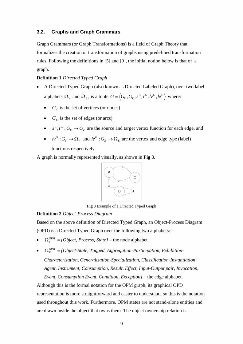
3.2. Graphs and Graph Grammars
Graph Grammars (or Graph Transformations) is a field of Graph Theory that
formalizes the creation or transformation of graphs using predefined transformation
rules. Following the definitions in [5] and [9], the initial notion below is that of a
graph.
Definition 1 Directed Typed Graph
A Directed Typed Graph (also known as Directed Labeled Graph), over two label
alphabets V and E , is a tuple GGGG
EV lelvtsGGG ,,,,, where:
VG is the set of vertices (or nodes)
EG is the set of edges (or arcs)
VE
GG GGts :, are the source and target vertex function for each edge, and
VV
G Glv : and EE
G Gle : are the vertex and edge type (label)
functions respectively.
A graph is normally represented visually, as shown in Fig 3.
A
B
C
1
3
2
4
Fig 3 Example of a Directed Typed Graph
Definition 2 Object-Process Diagram
Based on the above definition of Directed Typed Graph, an Object-Process Diagram
(OPD) is a Directed Typed Graph over the following two alphabets:
OPM
V {Object, Process, State} – the node alphabet.
OPM
E {Object-State, Tagged, Aggregation-Participation, Exhibition-
Characterization, Generalization-Specialization, Classification-Instantiation,
Agent, Instrument, Consumption, Result, Effect, Input-Output pair, Invocation,
Event, Consumption Event, Condition, Exception} – the edge alphabet.
Although this is the formal notation for the OPM graph, its graphical OPD
representation is more straightforward and easier to understand, so this is the notation
used throughout this work. Furthermore, OPM states are not stand-alone entities and
are drawn inside the object that owns them. The object ownership relation is

10
abstracted by adding a new type of link, Object-State, which denotes that a state
belongs to the object. Since the notation in OPM is more expressive and is part of the
OPD syntax, we use it, bearing in mind that it can be changed to the formal Object-
State link representation by detaching the state from the owning object, moving it out
of the object, and adding a link between the object and the detached state.
An OPM model is a graph of graphs, where each node in the model is an OPD and the
links between these nodes are defined by the refinement/abstraction (in- zooming/out-
zooming or unfolding/folding) relations between the OPDs.
Before we delve into the formalisms of graph grammars, we need to define the
following concepts.
Definition 3 Graph Morphism
Let GGGG
EV lelvtsGGG ,,,,, and '''' ,,,,','' GGGG
EV lelvtsGGG be two
graphs over the same label alphabets V and E . A Graph Morphism
': GGf is a pair of functions EEeVVv GGfGGff ':,': such that:
EGe , ))(())(( ' efsesf e
GG
v (source node preservation)
EGe , ))(())(( ' eftetf e
GG
v (target node preservation)
VGv , ))(()( ' vflvvlv v
GG (node label preservation)
EGe , ))(()( ' efleele e
GG (edge label preservation)
Graph morphism is a function that matches two graphs, preserving its structure (nodes
and edges) and the labels on the edges.
Definition 4 Subgraph
Suppose A , B , and 'B are sets, such that BB ' , and there exists a mapping
ABm : . The operator '' Bmm defines a new mapping 'm such that
)()(',' bmbmBb .
Let G be a graph as defined above. A subgraph SSSS
EV lelvtsSSS ,,,,, of G
, written GS , is a graph having VV GS , EE GS , ES
GS ss , ES
GS tt ,
VS
GS lvlv and ES
GS lvle .
Simply put, a subgraph is a part of a graph that is also a valid graph.
Definition 5 Partial Graph Morphism

11
A partial graph morphism : 'm G G is a graph morphism of a subgraph of G to
'G .
Having defined the above terms, we can now turn to the definitions of the graph
grammar needed in this work. The basic operation in graph grammars is graph
transformation, defined by a rule. There are two major approaches to defining
transformation rules: the double pushout approach (known as DPO) and the single
pushout approach (known as SPO). We use SPO since it is simple to define and
understand and we have no need for the strong properties that the DPO approach
features.
Definition 6 SPO Production Rule
A production RLp r: consists of a production name p and a partial graph
morphism r , called the production morphism. L and R are graphs called the left-
hand graph and the right-hand graph, respectively.
The left-hand graph of the production describes the context needed for the production
to be applied, and the right-hand graph shows how the original part of the graph will
look like after the application of the production rule. The morphism r specifies which
element (node or edge) in the left-hand graph is matched with which element in the
right-hand graph. To apply this production to a graph, each element missing in the
right-hand graph is deleted, and if this deletion causes dangling edges, they are
deleted as well. Elements missing in the left-hand graph that exist in the right-hand
graph are added. Formally, the application of a production is defined as follows.
Definition 7 Production, Derivation
A match for RLp r: in some graph G is a graph morphism GLm : .
Given a production p and a match m for p in graph G , the direct derivation
from G with p at m , written HGmp,
, is done as follows:
Using morphism m , delete vertices and edges of G that occur in L and do
not occur in R .
Add to G all vertices and edges that occur in R but do not occur in L .
If a node or an edge is both kept and deleted, solve the conflict by deletion (a
node or an edge is kept and deleted if it has two pre-images in L, one in R and
the other not in R).
Delete all dangling edges from G .

12
Example 1
We demonstrate the basic graph grammar concepts on a small OPD. The grammar's
set of production rules is given in Fig 4. Recall that an OPM object is denoted as a
rectangle and a process—as an ellipse.
Production 1:
Consumption Link Insertion P
O
P
O
Fig 4 The production of Example 1
The initial graph for our example is 1G , shown in Fig 5.
1G =
Object1
Object2
Object3
Process1
Process2
Fig 5 Initial graph of Example 1
Let us apply Production 1 – Consumption Link Insertion on 1G . The first step is to
find a subgraph of the graph 1G that matches the left-hand side of Production 1.
There are six possible matches: {Object1, Process1}, {Object1, Process2}, {Object2,
Process1}, {Object2, Process2}, {Object3, Process1} and {Object3, Process2}. We
choose to apply the rule on {Object1, Process1}, resulting in graph 2G , shown in Fig
6.
2G =
Object1
Object2
Object3
Process1
Process2
Fig 6 Example 1 graph after application of Production 1 – Consumption Link Insertion

13
Using derivations, we can describe how graphs are legally transformed into other
graphs. However, specifying when these transformations can be applied is limited by
the positive condition in the left-hand graph. This is extended with application
conditions, which specify contexts in which the transformation can be applied.
To add application conditions, we specify not just one left-hand side graph L , but a
set of graph morphisms }ˆ{ LL l called constraints [15], [8], [14]. Each constraint
represents a structure on the left-hand graph that must exist for positive constraints
and must not exist for negative constraints.
Definition 8 Application Conditions
An application condition over a graph L is a finite set }{ QLAl
of graph
morphisms of the form QLl
called constraints.
Let RLp r: be a production, QLa l
: a positive constraint, and
GLm : a match for L in graph G. We say that m satisfies a , denoted by
am | , if there exists a graph morphism GQn : such that mln , where
is the mathematical function composition operator, which means that we apply
morphism l to L and then we apply morphism n to the result.
A negative constraint is defined as a regular constraint for which morphism n
must not exist.
A match m satisfies an application condition A over L , denoted by Am | if it
satisfies all the constraints Aa .
Usually, the specified constraints are negative, since the positive constraints can be
modeled in the left-hand side graph of the production. Negative constraints can also
be embedded in the left-hand side graph of the production, where the common
notation is to draw them inside a shaded area, as shown in Example 2.
Definition 9 Conditional Production
A conditional production ),(ˆ ARLp p is a pair consisting of a partial graph
morphism p and an application condition A over L .
Definition 10 Direct Conditional Derivation
Production p̂ is applicable to graph G at GLm if Am | . This is called a
direct conditional derivation, denoted as HGmp,ˆ
.
Example 2

14
Continuing with the transformation in Example 1, we revise Production 1 to include a
negative constraint, which removes the possibility of creating duplicate consumption
links between two entities. The result is shown in Fig 7.
Production 1n:
Consumption Link Insertion P
O
P
O
Fig 7 Production 1 with a negative constraint
The rephrased Production 1, called Production 1n, simply means that a consumption
link can only be added if a consumption link between the two entities does not yet
exist. The addition of the negative constraint does not change the resulting graph in
Fig 6, but it rules out the option (Object3, Process2) from the set of possible
matches.
4. Formal Validation of an OPD using Graph
Grammars
There are two possible approaches to maintaining the syntactic correctness of an
OPD:
1) Proactive Verification: Maintaining syntactic correctness of the OPD at modeling
time by proactively verifying that each modeling operation is legal as it is being
executed by the system designer, so the model is guaranteed to be syntactically
correct by construction at any time. This approach is fairly complicated and may
encumber the user, because there may be intermediate situations in which the
model needs to be temporarily inconsistent.
2) Retroactive Verification: Verifying retroactively that the OPD has remained
syntactically correct after applying one or more modeling operations to the OPD.
Our syntactic correctness checking algorithm combines the proactive and retroactive
verification approaches. We limit the OPD construction process by defining
transformation rules stipulating what is and what is not permitted in OPD construction
while allowing for temporary inconsistencies.
This section shows part of a graph grammar for creating and validating a system
model in a single OPD. The zooming and folding OPM capabilities are not handled
since for syntactic purposes an OPM model that consists of many OPDs can be

15
recursively converted into a single OPD by "flattening" the OPD hierarchy via
successive model element assignments without loss of model information. The
complete definition of the OPD graph grammar can be found in [2].
4.1. OPD Creation – Sample OPD Graph Grammar Productions
The creation of an OPD starts with an empty graph, and from this empty graph any
number of productions is applied until the desired model is achieved. Some of the
productions that can be used to create an OPD are shown in Fig 8. Note that T is the
symbol of a Thing (Object or Process). For example, Production 1, Simple Thing
Creation, states that if Thing T does not exist, it can be created. Also note that in some
cases links are modeled using wildcard notations, meaning that the link can be
matched either to any link kind (when the links is drawn as a straight line), to
structural links (a straight line with an ‗s‘ in the middle) or procedural links (a straight
line with a ‗p‘ in the middle.
T
T
Production 1 Simple Thing Creation
O
S
O
S
Production 2 New State Creation
EW
T1
T
Production 3 Thing Removal
O1
O2
s
O1
O2
Production 4 Object-Pair Aggregation-
Participation Link Creation

16
T1
T2
s
T1
T1
Production 5 Exhibition-Characterization Link
Creation
O Pp
O P
Production 6 Agent Link Creation
T1 T2
T1 T2
Production 7 Link Removal
Fig 8 Sample Productions of the OPD graph grammar
4.2. OPD Validation
Validation of an OPD employs the OPD Abstraction algorithm, defined below. The
validation is done by searching for illegal constructs during the abstraction process. If
the algorithm does not find any illegal constructs, then the OPD is valid, at least
syntactically.
As noted, this work is applicable to a single OPD. A single OPD may contain a
complete OPM model or only part of a greater system model with other
interconnected OPDs.
The word abstraction is used in this context differently than in OPM, therefore it
needs to be clarified. Abstraction is used to denote reduction of the amount of
syntactic and semantic information in the model without contradicting the original
semantics of the model. In the context of an OPD, an element of the OPD can be
abstracted into another element if the new element does not contradict the meaning of
the original element, and no other element can abstract the original element being
abstracted without losing more semantic information.
The best way to understand this is by an example, as shown in Fig 9.
O1 P1
O1 P1
Fig 9 Abstraction of a simple OPM link
The left hand side diagram of Fig 9 shows that the object O1 is an instrument of the
process P1. The semantics of this OPD is that O1 is required for P1's execution. In the
17
right hand side diagram the instrument link is changed to an effect link. Semantically,
an effect link also denotes that P1 requires O1, but it adds to this that P1 affects O1
by changing its state. There is loss of information, because the effect link has a
broader definition. However, since the effect link does not contradict the semantics of
the original instrument link, the former link can abstract the latter.
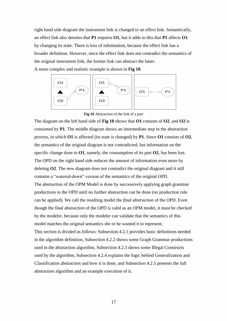
A more complex and realistic example is shown in Fig 10.
O1
O2
P1
O1
O2
P1
O1 P1
Fig 10 Abstraction of the link of a part
The diagram on the left hand side of Fig 10 shows that O1 consists of O2, and O2 is
consumed by P1. The middle diagram shows an intermediate step in the abstraction
process, in which O1 is affected (its state is changed) by P1. Since O1 consists of O2,
the semantics of the original diagram is not contradicted, but information on the
specific change done to O1, namely, the consumption of its part O2, has been lost.
The OPD on the right hand side reduces the amount of information even more by
deleting O2. The new diagram does not contradict the original diagram and it still
contains a ―watered-down‖ version of the semantics of the original OPD.
The abstraction of the OPM Model is done by successively applying graph grammar
productions to the OPD until no further abstraction can be done (no production rule
can be applied). We call the resulting model the final abstraction of the OPD. Even
though the final abstraction of the OPD is valid as an OPM model, it must be checked
by the modeler, because only the modeler can validate that the semantics of this
model matches the original semantics she or he wanted it to represent.
This section is divided as follows: Subsection 4.2.1 provides basic definitions needed
in the algorithm definition, Subsection 4.2.2 shows some Graph Grammar productions
used in the abstraction algorithm, Subsection 4.2.3 shows some Illegal Constructs
used by the algorithm, Subsection 4.2.4 explains the logic behind Generalization and
Classification abstraction and how it is done, and Subsection 4.2.5 presents the full
abstraction algorithm and an example execution of it.

18
4.2.1. Definitions and Notation
1. Temporary Link: The abstraction algorithm defined below works iteratively,
trying to abstract one thing in every iteration. During the abstraction process,
there are cases when new links are inserted into the OPD. These are called
temporary links and are modeled with a curved connection, as shown in Fig
11.
O1 P
O1 P
Fig 11 Temporary instrument link (left) and result link (right)
The difference between temporary links and regular links is that during the
one algorithm iteration the type of temporary links may be changed by the
abstraction algorithm. For example, suppose the algorithm received the
context shown in the left-hand graph of Fig 12. This can occur if P uses
another aggregate of O1 as an instrument (not shown in the drawing) which
was previously abstracted. Since the instrument link from O1 to P was created
by the abstraction algorithm, it can be further abstracted to an effect link as
shown in the right-hand graph of Fig 12.
O1
O2
P
O1
O2
P
Fig 12 Example of uses of temporary link
In contrast, if the instrument link was not temporary, but rather a modeling
decision (made by a modeler), the algorithm would not be able to change its
type and we would have an illegal construct in the model, This is so because a
change of a part cannot be abstracted by the whole being an instrument, since
an instrument is by definition an enabler that cannot be changed.
2. Structural Parent: the structural parent of a thing 1t is a thing 2t that is a
source of a structural relation ending at 1t (relations like Generalization and
Instantiation are structural relations). The set of structural parents of a thing 1t
is denoted by )( 1tSP .
19
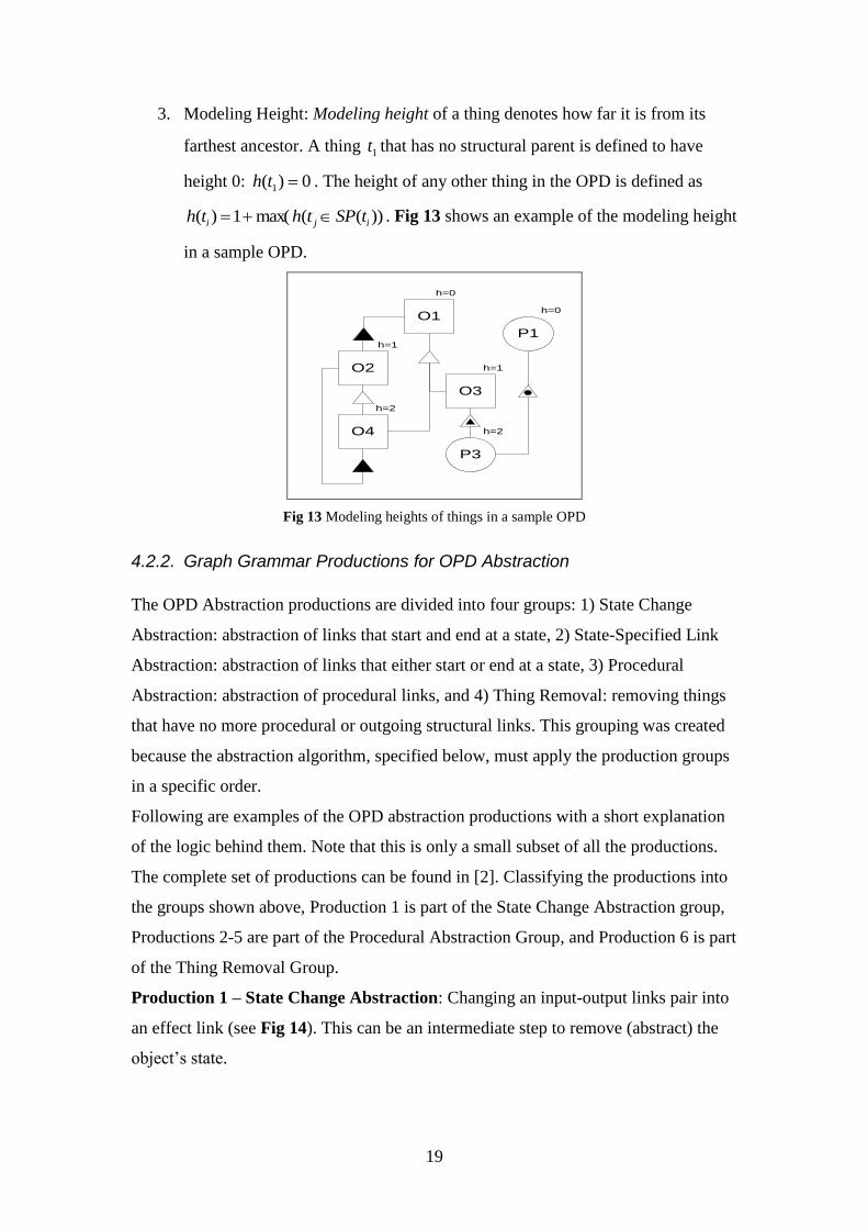
3. Modeling Height: Modeling height of a thing denotes how far it is from its
farthest ancestor. A thing 1t that has no structural parent is defined to have
height 0: 0)( 1 th . The height of any other thing in the OPD is defined as
))((max(1)( iji tSPthth . Fig 13 shows an example of the modeling height
in a sample OPD.
O1
O2
O3
O4
P3
h=1
h=0
h=1
h=2
P1
h=0
h=2
Fig 13 Modeling heights of things in a sample OPD
4.2.2. Graph Grammar Productions for OPD Abstraction
The OPD Abstraction productions are divided into four groups: 1) State Change
Abstraction: abstraction of links that start and end at a state, 2) State-Specified Link
Abstraction: abstraction of links that either start or end at a state, 3) Procedural
Abstraction: abstraction of procedural links, and 4) Thing Removal: removing things
that have no more procedural or outgoing structural links. This grouping was created
because the abstraction algorithm, specified below, must apply the production groups
in a specific order.
Following are examples of the OPD abstraction productions with a short explanation
of the logic behind them. Note that this is only a small subset of all the productions.
The complete set of productions can be found in [2]. Classifying the productions into
the groups shown above, Production 1 is part of the State Change Abstraction group,
Productions 2-5 are part of the Procedural Abstraction Group, and Production 6 is part
of the Thing Removal Group.
Production 1 – State Change Abstraction: Changing an input-output links pair into
an effect link (see Fig 14). This can be an intermediate step to remove (abstract) the
object‘s state.

20
O
S1
S2
P
PO
S1
S2
Fig 14 State Change Abstraction production
Production 2 – Promotion of Part Consumption to Aggregate Effect:
Consumption of a part object affects the aggregate object. Since in the diagram there
is no specified relation between O1 and P, the fact that it is affected by P must be
added to the diagram. After this is done, the link between O2 and P is removed. The
production is shown in Fig 15.
O1
O2
P
O1
O2
P
Fig 15 Promotion of Part-Consumption to Aggregate Effect production
Production 3 – Part Consumption Removal while Abstracting Instrument to
Effect: Consumption of a part means change to the aggregate. Since in Fig 16 the link
between O1 and P was created by the abstraction algorithm, its kind can be changed
as long as its new kind expands the meaning of the original link. Here, the instrument
link between O1 and P can be abstracted to an effect link, and then removed.
O1
O2
P
O1
O2
P
Fig 16 Part Consumption Removal while Abstracting Instrument to Effect production
Production 4 – Part Effect Removal via Result: In Fig 17, the process P on the left
hand side OPD yields O2 as a part of O1, so the result link from P to O2 can be
removed. The production also uses a shorthand notation for the link between O1 and
P, meaning that it can be applied regardless of whether the link is temporary or not.

21
O1
O2
P
O1
O2
P
Fig 17 Part Effect Removal via Result production
Production 5 – Part Effect Removal via Agent: An agent link implies optional
effect to the object, therefore the aggregate process P1 implies optional effect to O,
which abstract effect caused by P2, so the link between P2 and O is removed. The
production is shown in Fig 18.
P1
P2
O
P1
P2
O
Fig 18 Part Effect Removal via Agent production
Production 6 – Thing Removal: If the thing being considered for removal has no
procedural link or outgoing structural links, it can be removed from the OPD. Note
that the thing removed must be matched to T1. The production is shown in Fig 19.
T1Thin
g1T2 p
T3
s
T4
s
T4
Fig 19 Thing Removal production
4.2.3. Illegal Constructs
Illegal constructs are OPM constructs that create invalid or contradictory semantics in
the model. If one of these constructs is found in the OPD, or is created by the
abstraction algorithm, the OPD becomes invalid.
Below we show a number of illegal OPM constructs, which can occur in the local
context of the abstraction algorithm. Next to each construct is a brief explanation on
the rationale behind the illegality of the construct.

22
Illegal Construct 1 – Part Consumption and Aggregate Instrument: The
consumption link in Fig 20 between P and O2, that signifies change to O1,
contradicts the instrument link between O1 and P, which signifies no change to O1.
O1
O2
P
Fig 20 Part Consumption and Aggregate Instrument illegal construct
Illegal Construct 2 – Exhibitor Effect and Attribute Result:
The effect link between P1 and O in Fig 21 is less specific than the fact that O is
created by an attribute of P1.
P1
P2
O
Fig 21 Exhibitor Effect and Attribute Result illegal construct
4.2.4. Generalization and Classification Abstraction
The generalization-specialization relation can link two objects or two processes.
When two processes are related with a generalization-specialization link, the
abstraction process must validate that the ―signature‖ or "API"1 of the source of the
relation is maintained in the target of the relation. The signature of a process consists
of all incoming and outgoing procedural links, including the object types that are at
the ends of these links. An example of an OPD that is invalid because the signature of
a process is not inherited correctly is shown in Fig 22.
2D
Figure
Square
Paint
Paint on
Screen
Canvas
Screen
1 API – An application programming interface (API) is a source code interface that an operating system
or library provides to support requests for services to be made of it by computer programs

23
Fig 22 Invalid signature example
Process Paint requires 2D Figure and affects Canvas. Paint on Screen is a Paint,
therefore it must conform to the same signature as Paint, meaning that it must require
an object of type 2D Figure and must affect an object of type Canvas. Since this is
not the case, this OPD is invalid.
The signature of the process must be maintained, but may be expanded by creating
new links in addition to the links that already exist in the original signature.
The signature validation relies on the type of a thing. Each modeled thing in OPM has
at least one type2, and the OPM generalization or classification relations create a type
hierarchy. For each thing:
Each modeled thing is always of a primitive type. A modeled process named
pname is of type ptypepname _ . A modeled object named oname
is of type otypeoname _ . The primitive type of a thing is denoted as
)_( namethingT .
Using the OPM generalization-specialization relation, we can model the fact that one
thing specializes another thing, inheriting its features (i.e., attributes and operations),
relations and states3. This means that the specialized thing becomes of the type of the
general entity. This creates the Type Closure of a thing, denoted by
)_( namethingTC , such that:
)1()2()1(21
thingTthingTCthingTCthingthing
, where
21 thingthing denotes that thing1 is a thing2, as modeled in OPM using
the generalization-specialization relation.
If thing1 is an instance of thing2, then
)1()2()1( thingTthingTCthingTC .
For example, suppose P1 and P2 are two processes. From the definition above,
process P1 is of type P1_ptype and P2 is of P2_ptype. Furthermore, suppose that P1
2 The word type rather than class has been selected since class is used in most languages to define
objects, and this might confuse the reader.
3 The Generalization-Specialization relation in OPM is usually called inheritance in modern object
oriented languages.

24
and P2 are connected with a Generalization-Specialization link, where P1 is the
source of the link and P2 is the target of the link. Then P2 is also of type P1_ptype.
Using the above definitions, the signature consistency validation verifies that all
processes that are part of a generalization-specialization relation have the same
signature. The algorithm checks each procedural link of the parent in the relation, and
searches for a matching link in the child of the relation. When such link is found, it
verifies that the type closure of the connected element in the child‘s relation matches
at least one element in the type closure of the connected element in the parent‘s
relation. The algorithm succeeds if all of the links in the parent are valid.
4.2.5. OPD Abstraction and Validation Algorithm
As stated above, the OPD Abstraction and Validation algorithm tries to abstract the
OPD as much as possible, while continuously checking that the syntax and semantics
of the OPD remain valid.
The first step of the algorithm is the signature consistency validation. This must be
done before the abstraction of the OPD since the abstraction may change and remove
the links in the graph invalidating the API.
The second step of the algorithm is the core of the abstraction process. The algorithm
runs on all of the things ordered by their modeling height descending. The result of
each iteration can be: (1) removal of the processed thing, if all of the outgoing links
from the thing were removed by the abstraction productions; (2) marking the thing as
processed if the algorithm could not remove it but did not find any illegal construct
after all abstraction productions, or (3) finding an illegal construct in the context of
the processed thing.
The abstraction process is done in three steps. The first step is to abstract all of the
states of the thing (if it has any). This is done in order to transfer all the links to the
thing being abstracted. For example, suppose an object is consumed by a process
only when it is in a specific state. The abstraction process would cause the model to
show that the process consumes the object, regardless of its current state. As
expected, some information is lost, but the ―strongest‖ consequence of the link,
namely that the process consumes the object, is maintained.
The algorithm then tries to transfer all the links that originate from the current thing
to its parent, using procedural abstraction productions. Note that because there are
many (116 to be exact) abstraction productions, specifying them all in the algorithm

25
would make it unreadable, so they have all been called Procedural Abstraction. Their
classification is refined in [2] using link types as the basis for classification. The
purpose of this step is to remove as much information as possible from the thing
being abstracted, up to the point that it is not the source of any procedural link. As in
the state abstraction process, this may cause some information loss. For example,
suppose object O1 consists of object O2 and O3, and P1 is a process that consumes
O3. When object O3 is abstracted, the consumption link to P1 is transferred so it
starts at O1 while also being changed to an effect link (since this is the defined
semantic of consumption of an aggregate). After this abstraction, the model is still
correct, but less informative.
A description of the algorithm in pseudo code follows.
Input: OPD
Algorithm:
1. Validate all Process signatures by applying the Signature Consistency Validation
algorithm. If validation fails, stop and return failure on signature validation.
2. While OPD contains things that have not been processed:
2.1. Of all the things in the current OPD select thing with max(height(thing)) and
no outgoing structural links.
2.2. Transform all Temporary Links that start at thing to Regular Links.
2.3. Apply State Change Abstraction productions to thing if applicable, as many
times as possible.
2.4. Apply State-Specified Link Abstraction productions to thing if applicable, as
many times as possible.
2.5. Apply Procedural Abstraction productions to thing if applicable, as many
times as possible.
2.6. Check Illegal Constructs on thing. If at least one illegal construct exists, stop
and return failure on thing.
2.7. Apply Thing Removal production to thing if applicable. If the production is
not applicable, mark thing as processed.
3. Transform all temporary links in the OPD to regular links.
4. End.

26
The best way to understand the algorithm is through an example, where we validate
SD1 of the ABS Ford system model example provided by OPCAT [7] (the OPM
modeling tool) shown in Fig 23.
ABS
BrakingABS
Brake
Assembly
Mechanical
Subsystem
Hydraulic
Subsystem
Sensor
Subsystem
Engine
Control Unit
Power
Management
SystemVelocity
Driver
Passive Active
High Zero
Braking
Boosting Signal
Detecting
Anti
Locking
Actuating
Signal
Set
Actuating
Pulse Set
Fig 23 ABS Ford System Model SD1
The algorithm selects a thing with the highest height to start the abstraction. For
example, suppose Brake Assembly is selected first. The first production that can be
applied is State-Change Abstraction, as shown in Fig 24.
Brake
AssemblyPassive Active Braking
Brake
AssemblyBraking
Fig 24 State change abstraction on Brake Assembly
State-Specified Link Abstraction is then applied, as shown in Fig 25.
Brake
Assembly
Boosting
Signal
Detecting
Active
Brake
Assembly
Boosting
Signal
Detecting
Fig 25 State-Specified Link abstraction on Brake Assembly
The next step in the algorithm is Procedural Abstraction. In this step, the procedural
links that connect Brake Assembly to all other things in the diagram are migrated as

27
temporary links to its structural parent, which is ABS. The result of this is shown in
Fig 26.
Brake
Assembly
Braking
Boosting
Signal
Detecting
ABS
Fig 26 Example diagram after initial abstraction of Brake Assembly
No illegal constructs were detected on Brake Assembly, so the next step is Thing
Removal, which removes Brake Assembly from the diagram with the result show in
Fig 27.
ABS
BrakingABS
Mechanical
Subsystem
Hydraulic
Subsystem
Sensor
Subsystem
Engine
Control Unit
Power
Management
System
Velocity
Driver
High Zero
Braking
Boosting Signal
Detecting
Anti
Locking
Actuating
Signal
Set
Actuating
Pulse Set
Fig 27 OPD diagram after first round of the abstraction algorithm
Since at each round of the algorithm a thing is removed or marked as processed, and
there is a limited number of things in the OPD, the algorithm will finish either when
there is no thing in the OPD not marked as processed, or if there were illegal
constructs found in the way.
The final result of the algorithm after a number of rounds is shown in Fig 28.

28
ABS
BrakingABS
Velocity
Driver
Fig 28 Final abstraction of the example diagram
Even though the algorithm validated the OPD and found it syntactically and
semantically correct, the final result of the algorithm provides the modeler with the
most simplified version of the system, which she or he must examine to see if the
abstract system model reflects the modeler‘s intent.
5. Conclusions
In this research we have formally defined the syntax of an OPD and a method for the
creation and verification of OPDs. This formalization provides OPM with a solid
software engineering foundation, as the syntactic and some of the semantic
correctness of models and diagrams can be verified. This formal verification is critical
as we wish to create robust and verifiable systems.
A formal and exact definition of the syntax and the semantics of OPM opens the way
for such desirable features as validation and automatic testing of systems at design
time. This formalism also supports system lifecycle management. As a system is
changed, these changes can be done in the system model and can be compared
semantically to the original model to detect what of the model were affected by the
change. This can greatly reduce the amount of testing needed when new versions of a
system are produced.
5. References
[1] Peterson, J.L, (1977), Petri Nets. ACM Computing Surveys 9, pp. 223-252
[2] Bibliowicz, A. (2008), A Graph Grammar-Based Formal Validation of an Object-Process Diagram,
M.Sc. Thesis, Technion, Israel, available at http://www.vainolo.com/files/research/A-Graph-Grammar-
Based-Formal-Validation-of-an-Object-Process-Diagram.pdf
[3] Breu, R.; Hinkel, U.; Hofmann, C.; Klein, C.; Paech, B.; Rumpe, B. & Thurner, V. (1997), Towards
a Formalization of the Unified Modeling Language, in 'ECOOP – 11th
European Conference in Object-
Oriented Programming', pp. 344-366, LNCS vol. 1241, Springer.
[4] Bruel, J. & France, R. B. (1998), Transforming UML models to Formal Specifications. Available:
http://www.cs.york.ac.uk/puml/papers/brueluml98.pdf.

29
[5] Corradini, A.; Ehrig, H.; Heckel, R.; Löwe, M.; Montanari, U. and Rossi, F. (1997), Algebraic
Approaches to Graph Transformation, Part I: Basic Concepts and Double Pushout Approach. in
Rozenberg, G., (ed). Handbook of Graph Grammars and Computing by Graph Transformation, Vol. 1:
Foundations, World Scientific, Singapore, 1997.
[6] Dori, D. (2002), Object-Process Methodology: A Holistic Systems Paradigm, Springer-Verlag New
York, USA.
[7] Dori. D, Linchevski C., and Manor R. (2010), ‗OPCAT – A Software Environment for Object-
Process Methodology Based Conceptual Modeling of Complex Systems‘, in Proceedings 1st
International Conference on Modelling and Management of Engineering Processes, University of
Cambridge, Cambridge, UK, pp 147-151.
[8] Ehrig, H.; Ehrig, K.; Habel, A. & Pennemann, K. (2004), Constraints and Application Conditions:
From Graphs to High-Level Structures, in 'ICGT 2004 – 2nd
International Conference in Graph
Transformations', pp. 287-303, LNCS vol. 3256, Springer.
[9] Ehrig, H.; Heckel, R.; Korff, M.; Lцwe, M.; Ribeiro, L.; Wagner, A. & Corradini, A. (1997),
Algebraic approaches to graph transformation. Part II: single pushout approach and comparison with
double pushout approach, in 'Handbook of Graph Grammars and Computing by Graph Transformation.
Vol. I: Foundations', World Scientific, pp. 247-312 .
[10] Evans, A.; France, R. B.; Lano, K. & Rumpe, B. (1999), The UML as a Formal Modeling
Notation, in 'UML '98: Selected papers from the First International Workshop on The Unified
Modeling Language UML', pp. 336-348., LNCS vol. 1618, Springer.
[11] France, R. B.; Ghosh, S.; Dinh-Trong, T. & Solberg, A. (2006), 'Model-Driven Development
Using UML 2.0: Promises and Pitfalls', Computer 39(2), 59.
[12] Gogolla, M. & Parisi-Presicce, F. (1998), State Diagrams in UML: A Formal Semantics using
Graph Transformations, in Manfred Broy; Derek Coleman; Tom S. E. Maibaum & Bernhard Rumpe,
ed.,'Proceedings PSMT'98 Workshop on Precise Semantics for Modeling Techniques', Technische
Universitat München, TUM-I9803, .
[13] Kuske, S.; Gogolla, M.; Kreowski, H. J and Ziemann, P. (2009), Towards an Integrated Graph-
Based Semantics for UML, Software and Systems Modeling 8(3), pp. 385-401, Springer.
[14] Habel, A.; Heckel, R. & Taentzer, G. (1996), 'Graph grammars with negative application
conditions', Fundam. Inf. 26(3-4), 287-313.
[15] Heckel, R. (1995), Embedding of conditional graph transformations', in Valiente Feruglio G. &
Rosello Lompart F., ed., 'Proceedings Colloquium on Graph Transformation and its Application in
Computer Science', Technical Report B-19, Universitat de les Illes Balears.
[16] Jürjens, J. (2002), A UML statecharts semantics with message-passing, in 'SAC – Proceedings of
the 2000 ACM Symposium on Applied Computing', pp. 1009-1013.
[17] Kobryn, C. (2004), 'UML 3.0 and the future of modeling', Software and Systems Modeling 3(1),
pp. 4-8, Springer.
[18] Kong, J.; Zhang, K.; Dong, J. & Song, G. (2003), A Graph Grammar Approach to Software
Architecture Verification and Transformation, in 'COMPSAC '03: Proceedings of the 27th Annual

30
International Conference on Computer Software and Applications', IEEE Computer Society,
Washington, DC, USA, pp. 492.
[19] Kuske, S. (2001), A Formal Semantics of UML State Machines Based on Structured Graph
Transformation, in 'Proceedings of the 4th International Conference on The Unified Modeling
Language, Modeling Languages, Concepts, and Tools', pp. 241-256, LNCS vol. 2185, Springer.
[20] Mwaluseke, G. W. & Bowen, J. P. (2001), 'UML Formalisation Literature Survey', at
http://citeseerx.ist.psu.edu/viewdoc/summary?doi=10.1.1.119.9075.
[21] Nestor, A. O., 'Modeling of large and complex applications with UML', at
http://citeseerx.ist.psu.edu/viewdoc/summary?doi=10.1.1.4.3347.
[22] Object Management Group (2003), 'Unified Modeling Language (UML) 2.0 Infrastructure
Specification', at http://www.uml.org/.
[23] Reinhartz-Berger, I. & Dori, D. (2005), A Reflective Metamodel of Object-Process Methodology:
The System Modeling Building Blocks, in Peter Green & Michael Rosemann, ed.,'Business Systems
Analysis with Ontologies', Idea Group.
[24] Snook, C. & Butler, M. (2006), 'UML-B: Formal modeling and design aided by UML', ACM
Trans. Softw. Eng. Methodol. 15(1), 92-122.
[25] Soffer, P.; Golany, B.; Dori, D. & Wand, Y. (2001), 'Modelling Off-the-Shelf Information
Systems Requirements: An Ontological Approach', Requir. Eng. 6(3), 183-199.
[26] Spivey, J. M. (1989), The Z notation: A Reference Manual, Prentice-Hall, Inc., Upper Saddle
River, NJ, USA.
[27] Stцrrle, H. & Hausmann, J. H. (2005), Towards a Formal Semantics of UML 2.0 Activities, in
'Software Engineering', pp. 117-128.
[28] Tchertchago, A. (2002), 'Formal Semantics for a UML Fragment Using UML/OCL
Metamodeling', at http://citeseerx.ist.psu.edu/viewdoc/summary?doi=10.1.1.9.5869
[29] Thomas, D. (2004), 'MDA: Revenge of the Modelers or UML Utopia?', IEEE Software 21(3), 15-
17.
[30] USA Department of Defense (2009), ‗DoD Architecture Framework Version 2.0‘, at http://cio-
nii.defense.gov/sites/dodaf20/index.html
[31] Vanderperren, Y. & Dehaene, W. (2005), UML 2 and SysML: An Approach to Deal with
Complexity in SoC/NoC Design, in 'DATE', pp. 716-717.
[32] Wand, Y. & Weber, R. (1993), 'On the Ontological Expressiveness of Information Systems
Analysis and Design Grammars', Journal of Information Systems, 217-237.
[33] Ziemann, P.; Hölscher, K. & Gogolla, M. (2005), 'From UML Models to Graph Transformation
Systems', Electronic Notes in Theorethical Computer Science 127(4), 17-33.
Related Documents