Particle Accelerators 1973, Vol. 5, pp. 227-235 © Gordon and Breach, Science Publishers Ltd. Printed in Glasgow, Scotland A FLUX THEOREM FOR THE DESIGN OF MAGNET COIL ENDSt F. E. MILLS and G. H. MORGAN Brookhaven National Laboratory, Upton, NY, USA Analytical expressions are developed for the Fourier expansion coefficients integrated along the axis of the field of iron-free multipole magnets, or magnets having an infinitely permeable concentric circular shield. The method makes use of the mutual inductance of the magnet and an idealized, infinitely-long cos nO current sheet concentric with and interior to the magnet. The expressions obtained are used to verify a previously-known ideal end structure and also to compute the harmonics in a real magnet end on which measurements have been made. 1. INTRODUCTION The purpose of this paper is to develop analytical means to calculate the end effects of essentially two- dimensional accelerator and beam handling mag- nets with three-dimensional end coil distributions. In fact, means are developed to deal with this problem in an empirical way as well. The result is really an elaboration of a reciprocal theorem proved by Robinson 1 for use in the design of magnetic pickup electrodes. The problem has received attention at many accelerator centers, notably by Lambertson, 1 Meuser, 2 and Green 3 at the Lawrence Berkeley Laboratory, and Coupland 4 at the Rutherford Laboratory, but the present treatment is developed in a different though presumably equivalent way_ We are interested in calculating the quantities (1) where the qn are lin of the Taylor co- efficients _of the integral value of vertical field component By along the s-axis, x is distance on the median plane from the magnet axis, and s is the distance along the magnet axis. MKS units are used throughout. (We are not interested here in 'rotated' multipoles arising from midplane antisymmetric coils, although the development includes them up to a point.) OUf concern with the qn alone is equivalent to the assumption that the effect of the field on a traversing particle is equivalent to that of a field tWork done under the auspices of the U.S. Atomic Energy Commission. represented by a single axial component of vector potential acting over a finite distance. This is strictly true only if tpe particle does. not change radial or azimuthal position while traversing the field, i.e., the particle momentum is infinitely great An integral expression for the qn in terms of magnet coil parameters is obtained as follows: (1) We define a hypothetical coil of infinite length and infinitesimal thickness which produces a perfect 2n-pole field. The field of this 'linear n-pole' is obtained in terms of its parameters. (2) We show that the flux produced by the accelerator magnet which links the linear n-pole is expressible in terms of the qn defined above. (3) We calculate the flux produced by the linear n-pole which links the accelerator magnet coil. Since the mutual induct- ance theorem states that these two flux linkages are equal when the coil currents are equal, the qn are thus calculated from magnet coil parameters. To the extent that a coil representing the ideallinear n-pole can be manufactured, the result (2) expresses the qn in terms of coil parameters and measured linear n-pole flux change. The integral expression obtained is true for any three-dimensional coil configuration, with or with- out an infinite-Jl circular iron shield, but in the present paper it is applied only to infinitesimally thin coils lying on a circular cylinder, with or without a concentric iron shield. Although the formalism developed strictly applies only to complete coils, it will be seen that by the artifice of putting in ideal 'bedstead ends' in transition planes, the ends may be calculated independently of the main or s-independent sections of the windings.

Welcome message from author
This document is posted to help you gain knowledge. Please leave a comment to let me know what you think about it! Share it to your friends and learn new things together.
Transcript
Particle Accelerators1973, Vol. 5, pp. 227-235
© Gordon and Breach, Science Publishers Ltd.Printed in Glasgow, Scotland
A FLUX THEOREM FOR THE DESIGN OF MAGNET COIL ENDStF. E. MILLS and G. H. MORGAN
Brookhaven National Laboratory, Upton, NY, USA
Analytical expressions are developed for the Fourier expansion coefficients integrated along the axis of the field ofiron-free multipole magnets, or magnets having an infinitely permeable concentric circular shield. The methodmakes use of the mutual inductance of the magnet and an idealized, infinitely-long cos nO current sheet concentricwith and interior to the magnet. The expressions obtained are used to verify a previously-known ideal end structureand also to compute the harmonics in a real magnet end on which measurements have been made.
1. INTRODUCTION
The purpose of this paper is to develop analyticalmeans to calculate the end effects of essentially twodimensional accelerator and beam handling magnets with three-dimensional end coil distributions.In fact, means are developed to deal with thisproblem in an empirical way as well. The result isreally an elaboration of a reciprocal theorem provedby Robinson1 for use in the design of magneticpickup electrodes.
The problem has received attention at manyaccelerator centers, notably by Lambertson, 1
Meuser, 2 and Green3 at the Lawrence BerkeleyLaboratory, and Coupland4 at the RutherfordLaboratory, but the present treatment is developedin a different though presumably equivalent way_
We are interested in calculating the quantities
(1)
where the qn are lin of the Taylor expa~sion coefficients _of the integral value of vertical fieldcomponent By along the s-axis, x is distance on themedian plane from the magnet axis, and s is thedistance along the magnet axis. MKS units are usedthroughout. (We are not interested here in 'rotated'multipoles arising from midplane antisymmetriccoils, although the development includes them up toa point.) OUf concern with the qn alone is equivalentto the assumption that the effect of the field on atraversing particle is equivalent to that of a field
tWork done under the auspices of the U.S. AtomicEnergy Commission.
represented by a single axial component of vectorpotential acting over a finite distance. This isstrictly true only if tpe particle does. not changeradial or azimuthal position while traversing thefield, i.e., the particle momentum is infinitely great
An integral expression for the qn in terms ofmagnet coil parameters is obtained as follows:
(1) We define a hypothetical coil of infinite lengthand infinitesimal thickness which produces a perfect2n-pole field. The field of this 'linear n-pole' isobtained in terms of its parameters. (2) We showthat the flux produced by the accelerator magnetwhich links the linear n-pole is expressible in termsof the qn defined above. (3) We calculate the fluxproduced by the linear n-pole which links theaccelerator magnet coil. Since the mutual inductance theorem states that these two flux linkages areequal when the coil currents are equal, the qn arethus calculated from magnet coil parameters. Tothe extent that a coil representing the ideallinearn-pole can be manufactured, the result (2) expressesthe qn in terms of coil parameters and measuredlinear n-pole flux change.
The integral expression obtained is true for anythree-dimensional coil configuration, with or without an infinite-Jl circular iron shield, but in thepresent paper it is applied only to infinitesimallythin coils lying on a circular cylinder, with orwithout a concentric iron shield.
Although the formalism developed strictly appliesonly to complete coils, it will be seen that by theartifice of putting in ideal 'bedstead ends' intransition planes, the ends may be calculatedindependently of the main or s-independent sectionsof the windings.
228 F. E. MILLS AND G. H. MORGAN
2. LINEAR n-POLES
This is zero since the integrand of the first integralon the right is everywhere zero and the secondintegral is Bs l~ 00 = O. The solution to V2E = 0 nearthe origin in two dimensions is
as can be shown by direct substitution:
8E foo 8cp foo;- = ;-ds = - Brds,ur -oour -00
18E foo-;'ao = - -00 Beds.
The validity of differentiation under the integral isassumed, though proof is obvious if the variablesare separable. Then E satisfies the two-dimensionalLaplacian,
Then
and
satisfies Laplace's equation. O\ving to the finiteextent of the coil, B is zero as s approaches ± 00.
The potentialqJ is defined to be zero as s --+ ±00. Let
E(r,O) = f~oo <pds.
(2)
(3a)
(3b)
r~a
rza.ljJn = an rnsin nO
=bnr -n sin nO
J.l NI an (r n-1 1)Br = 0; sinnO R2n +rn + i
J.l N Ian ( rn
1)l/J = 0 0 sin nO - - -n 2n R2n rn
which satisfies the boundary condition l/Jn = 0 atr = R. Then
Using B = - Vl/J and applying boundary conditionsat r = a yields
an = lloINo/2nan, bn= -J.loNolanI2n.
If a circular cylindrical iron shell of radius Randinfinite permeability concentric with the linear npole surrounds it, the potential in the regiona ~ r :::;: R has two terms, one in r- n as before, theother in rn
• To obtain the coefficients, it is convenient to use the easily verified fact that a currentfilament at radius a is imaged at R 2Ia (if the currentreturn is on the axis). The coefficient of the newterm is then just the an with a replaced by R2la,giving
We choose a coil radius a, less than the radius of theaccelerator magnet coil, and an angular currentdensity dis/dO = INo cos nO. There are thus (Nola)cos nO turns per unit length of circumference, eachcarrying current I. The scalar potential is (subscripted 'a' is a coefficient, not the radius)
The equivalent boundary condition, B(J = 0 atr = R is also satisfied. The interior potential, thoughnot needed in the present development, from thecontinuity in Br at r = a, simply increases in theratio 1+(aIR)2n, i.e., a factor of 2 if R = a.
The field is also obtainable via B = V x A from avector·potential A which can be assunled zero at±00. The flux enclosed by a closed path c is given by
3. THE INTERIOR FIELD OF THEACCELERATOR MAGNET, AND FLUXLINKING THE LINEAR n-POLE
The interior field of the magnet is obtainable from ascalar potential qJ(r, (), s) via B = - VqJ, and qJ
where S is the surface which has c as its periphery.The sense of dS is positive when S lies on the left asc is traversed. For c choose two lines at (r1' ( 1) and(r2 , ( 2 ) parallel to the s-axis, with crossover at
DESIGN OF MAGNET COIL ENDS 229
sufficiently large ±s that A is zero. The flux betweenthem is
F 12 = f~CXJ AsCr2,82)ds- f~CXJ As(r1 ,81)ds,
where As is the axial component of A. Either ofthese integrals along a line at (r, B) is a twodimensional potential since it is independent ofpath. We define such an integral as F(r, B) andfurther observe that
f f f( lOAs dAo)Brds = (V x A)r ds = ;ao -a; ds
1 a f 100
loF= --::;- Asds-Aor vB - 00 r vB
dimensions was done for the case of fields interiorto a coil array, the treatment also applies to exteriorfields in iron and current-free space. The samesolutions are obtained, but with n negative. Following Beth,8 we denote by G the complex integratedfield:
G = Gx+iGy ,
where
Then
and
and
f f(OAr OAs')Bods = ai -a;: ds
1
00 af of= Ar _ 00 - or As ds = - or .
The same assumption as to differentiability underthe integral is made.
But then
i.e., since
a oz d dax oxdz dz
this is equivalent to
(
on-l foo ). ~ n-l By ds = n! qn
uX -00 r=O
and
loF oE-;'oB = -or (4a)
and
( on- 1IOO ) ·
a n- 1 Bx ds=n!Pnx -00 r=O
and
which are the Cauchy-Riemann equations in polarcoordinates. Accordingly, E and F are conjugatefunctions and <I> = F + iE is an analytic function ofz = x+iy. The solution for Fis
'L(qnrn cos nB-Pnrn sin nB), (5a)
<I> = 'L(qn + iPn)zn. (5b)
From A = (Jloj4n) SJ dvjr (Green's solution 'toPoisson's equation), As has the same symmetryproperties as Js, so if Js has midplane symmetry, sodoes As and the Pn are all zero.
With the mathematics reduced to two-dimensional5 form, a great deal of prior work is immediately applicable. 6
-9 Although the reduction to two (6)
Fn = I:" FNocosn8d8
= I:"No>;(qmamcosm8- Pmam sinm8) cosn8d8
which justifies the statement made in the introduction.
The flux linked by a lin.ear n-pole of radius ainterior to the accelerator magnet is easily calcu1ated using the flux potential F obtained above. Thefact that a wire and its return constitute a closedloop enclosing flux is not needed-the specificationof angular turns density by No cos nB includes thewinding direction sense; a (-) sign indicates thewire can be interpreted as a return. The flux linkageis then
(4b)of loEor=~aB'
230 F. E. MILLS AND G. H. MORGAN
To the extent that one can construct a perfect npole, this expression is useful for measurements ofharmonic content by the mutual inductancemethod.
4. FLUX FROM THE INTERIOR LINEARn-POLE LINKED BY THEACCELERATOR MAGNET
The major problem in characterizing the magnetends is that of an analytic representation for theends. This is somewhat simplified by the presentprocedure since the field produced by a linear n-polehas no s-component, making the flux linkagecalculation easier. However, windings with bothradial and azimuthal variation can introduce intractable problems of integration, making analyticresults difficult to obtain. The general flux linkageexpressions presented will be applied analyticallyonly to the simple and physically realizable case of'smooth' ends, defined as those which are developedin the same circular cylinder of radius b as the mainparallel winding. An important exception to this isthe ideal bedstead end in which all the crossovers liein a plane perpendicular to the s-axis and which hasno flux linkage with a linear n-pole. Such ends aredifficult to realize with real conductors since amathematical rigHt-angle bend can only be approached in practice. The importance of this end liesin its conceptual use as a termination to either theparallel windings or a more physically realistic end,thus allowing one to compute ends separately fromthe main winding.
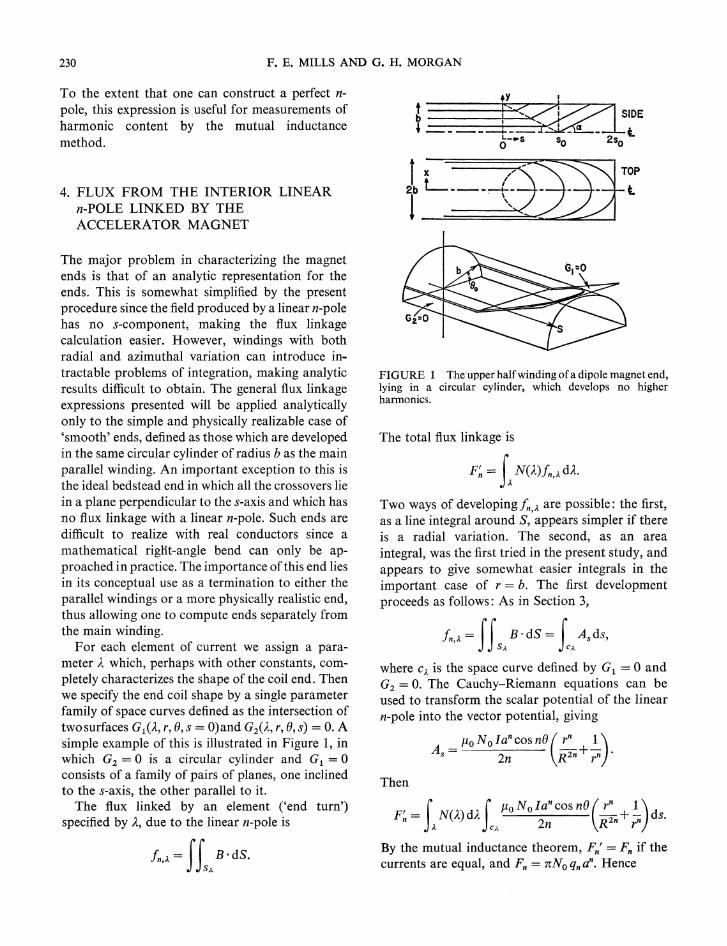
For each element of current we assign a para11leter A- which, perhaps with other constants, completely characterizes the shape of the coil end. Thenwe specify the end coil shape by a single parameterfamily of space curves defined as the intersection oftwo surfaces G1(A-, r, (), s = O)and G2(A, r, (), s) = o. Asimple example of this is illustrated in Figure 1, inwhich Gz = 0 is a circular cylinder and G1 = 0consists of a family of pairs of planes, one inclinedto the s-axis, the other parallel to it.
The flux linked by an element ('end turn')specified by A, due to the linear n-pole is
tY I
FIGURE 1 The upper half winding ofa dipole magnet end,lying in a circular cylinder, which develops no higherharmonics.
The total flux linkage is
F~ = 1.N(2)fn,;. d2.
Two ways of developingfn,;.. are possible: the first,as a line integral around S, appears simpler if thereis a radial variation. The second, as an areaintegral, was the first tried in the present study, andappears to give somewhat easier integrals in theimportant case of r = b. The first developmentproceeds as follows: As in Section 3,
in,;.. = II B·dS = JAsds,SA CA
where C;.. is the space curve defined by G1 = 0 andGz = O. The Cauchy-Riemann equations can beused to transform the scalar potential of the linearn-pole into the vector potential, giving
_ f1oNolanCOSn()(~ ~)As - 2n R Zn + r n •
Then
I _ f f flo N0 I an cos n()(~ ~) dsFn - N(A)dA 2 R2n + n •. ;.. CA n r
By the mutual inductance theorem, Fn' = Fn if thecurrents are equal, and Fn = nNoqnan. Hence
DESIGN OF MAGNET COIL ENDS 231
(10)
f
1t/2m
qn = -4mQn 0 N(eo)deo
I1t/2m
X s(8,80)sinn8d8, kodd (11)00
where coo is that part of the boundary lying between
where
This can be simplified by arguments based on synlmetry. First, see, (0) is symmetric in 8 around(2j-l)n/2m by construction. Second, if n ~ m andn/m = odd integer, then sin nO is symmetric around(2j - 1)n/2m; if n/m == even integer, it is antisymmetric. This can be shown by expandingsin n[(2j-l)n/2m+cp] and sin n[(2j-l)n/2m-cp]with nJm == k. With these results
Similar symmetry arguments applied to Eq. (7)yield for the line integral formulation, with r notconstant, but with G2 == 0 having 2-m pole symmetry.
2m/10 I f1t/2~qn == --- N(80)d80
nn 0
x f cosne( ~n+~)dS' (12)ceo R r
== 0, k even.
f
1ti/m-oo
X I s«(},80)sinn8dO,1t(i-l)/m+Oo
2m f1t(2i-l)/2m
qn = - Qn L (-lY N(Oo) dOoi=l 1t(i-l)/m
We consider a magnet winding on a circularcylinder of radius b required to produce a field with2m-pole symmetry, that is, the winding sense is thesame as cos m8: + for 'go' and - for 'return', i.e.,the sense reverses at alternate poles. The limits inthe integral in Eq. (9) then become
5. INTEGRAL LIMITS AND THEEVALUATION OF THE qn WITH SOMESYMMETRIC ANALYTIC FORMS FORGl AND G2
The specification of Gl (8, s, ( 0 ) == 0 is a compromise between mechanical engineering and fieldshaping. Some reasonable engineering demands arethat there be no discontinuities in dsJd8 at 8 == 80
(no sharp bends) and
ds I dp I- >-dN O=1t/2n = dN s=o'
where p = r8 is distance in the azimuthal direction,i.e., that the coils at the end be packed no tighterthan on the sides.
again with Gl == 0 and G2 == O. If G2(r, 8, s, A) == 0becomes r-b == 0, the second integral is zero (i.e.,no azimuthal flux is intercepted by the winding). Inthis case, an especially convenient choice for Ais thevalue 80 at which a current element lies in the 'mainparallel winding' before making the transition to'end'. The distribution in 80 is then dictated by thefunction of the magnet in question, i.e., cos n80 if anideal n-pole, or perhaps a step-function approximation to cos n80 • With this choice, and Gl (8,s, ( 0 ),
=0
/10 I f -[f ( rn
1)qn = ~. N(A)dA - sin ne R2n +;n s de
+fcosne(rn-l
1 )SdrJ (8)R2n rn+ 1 '
Using the expressions for B,. and Bo obtained inSection 2,
Qn=/120I j N(A)dAf cosne(r:n+~)dS; (7)nn ;. c;., R , r
with Gl and G2 specified the qn can now be computed. Notice that the properties of the linear n-pole,namely No and a, do not appear.
The second development for In,;. is as follows:
232 F. E. MILLS AND G. H. MORGAN
e = eo and e = nj2m. With s = constant in Eq. (11)and N(eo) = No cos meo the result is immediate;this is just the usual bedstead end. Further consideration leads one to the conclusion that any endconfigurations which are tractable analytically willbe made up of linear combinations of simplefunctions,. That is, we may evaluate a number ofsimple functions, then take combinations to create aphysically realizable end in which we may alsobalance out higher multipole contributions. Somechoices for see, eo) and the resulting coefficients aregiven in Table I, for dipoles (m = 1). In Table I u isequal to (_I)(n+ 1)/2 and has the value plus orminus 1.
TABLE I
Hannonic content of ends specified by some simple functions
s«(), ( 0 ) -q~/No Qi -qn/No Q"
Ki Kin 0
K2()o K2(n2-1)/44K2 2
-~n2_1)2[n +1 +2nu]
K3 sin (}o 4K3 /3 -4K3 /[n(n2-4)]±K4 cos (}o -8K4 u/3 8K4 u[n2(n2- 4)]
Ks sinO 4Ks/3 - 8Ks/[n(n 2-- 4)]±K6 cos () 4K6 /3 4K6 u/[n2-4]
We notice immediately that the combinations = so(1 +sin e - 2 sin eo) gives qn = 0 for all ngreater than 1. This is a configuration described toone of the authors by G. Lambertson some yearsback and apparently it or something similar hasbeen patented in Britain by J. H. Coupland. Asketch of this end (which we will term L-C forLambertson-Coupland) is shown in Figure 1.
As a short digression, we note that the methodfollowed by those authors shows that the contributions to qn come only from current elements inthe z-direction. If iron is present then one mustshow (but has not) that the contributions to qn fromiron magnetization correspond to those directlyfrom the coil. That is, in the language of images,that the image currents of current elements in the ror () directions do not have z components. In thepresent work that difficulty is overcome by the twodimensional character of the field of the linearn-pole. The essential agreement of the two methodsmay in fact be taken as a proof that the magnetization may be represented by three-dimensionalimages in the case of a cylindrical iron surface.
Resuming the discussion of Figure 1, the turns,following the sharp bend at the dashed line, follow aspace curve which is a section of an ellipse. Theangle a which the dashed plane of bends makeswith th~ median plane is equal to that which theplane containing the element eo = 0 makes with themedian plane. In practice, depending on conductorthickness and the angle a, the required sharpness ofbend might be hard to realize. A more difficultproblem arises with windings made up of ribbonconductors: a ribbon cannot follow an arbitraryspace curve. Although the center of gravity of anindividual ribbon might be made to follow a curveof the L-C sort, it is possible that the twist whichmust be put in the ribbon would lead to spacingerrors at e = nj2. If we denote azimuthal distancealong the periphery by p, then the spacing at e= nj2is given by dsjdN = Ij(dNjdp · dpjds), wheredNjdp = No cos eojb and dpjds = -bj(2so cos eo).Thus dsjdN = -2sojNo, i.e., the spacing along thetop is uniform. Present construction practice atBrookhaven of the main parallel winding requiresthe ribbons to lie essentially in planes containing thes-axis, thus the required sharp bend is easilyrealizable with ribbon conductors although thespatial curve of the L-C end is not.
6. CORRECTION OF EXISTING ENDS
Especially in the case of ribbon-wound magnets, theend shape, as already stated, is a compromise withmechanical requirements. Hence one may ask,given an existing satisfactory mechanical design, canit be modified to give satisfactory magneticperformance? Green3 described a procedure usedon quadrupoles which is essentially the following.From Eq. (7) for the qn given in Section 4, we note'that provided rand e are held constant, the harmonic content of a given element is proportional toits length. This linearity implies that, given anarbitrary harmonic content, one can always find ans(eo) (an axial spacing distribution) which willexactly null it. (If the number of elements is finite,the number of harmonics which can be nulled isalso finite.) However, the solution so obtained maynot satisfy the axial spacing requirements, Eq..(10)of Section IV. But given a sufficient number ofelements, it may be hoped that at least a few of the
DESIGN OF MAGNET COIL ENDS 23
TABLE IICalculated and measured harmonic coil voltages
which the windings lie. This very crude approximation to a quite complex reality gives calculatedharmonics which agree well with measured harmonic content, as shown in Table II in terms ofmeasuring coil voltage ratios. The harmonic coil12
integrates over the entire end, being a single-turn,finite-length approximation to the 'linear n-pole'described earlier.
The B1 of Table II is the signal voltage of the coilwhen centered in the main parallel winding, not thedipole contribution of one end, which, though notmeasured, is calculated to be 18.6 per cent of themain winding. The remarkably good agreement ofmeasurement with calculation indicates that theharmonic content is not very sensitive to curveshape.
The integrations of Eq. (11) required to computethe model harmonics were performed numerically.With four blocks of current, one can change threeaxial spacings, giving three parameters to adjust tonull the 6, 10 and 14-pole harmonics. A computerprogram was written which computes the harmoniccontent of arbitrary lengths of filaments centered on
lowest order components can be nulled; thosewhich are not nulled are at least minimized, as thefollowing example shows.
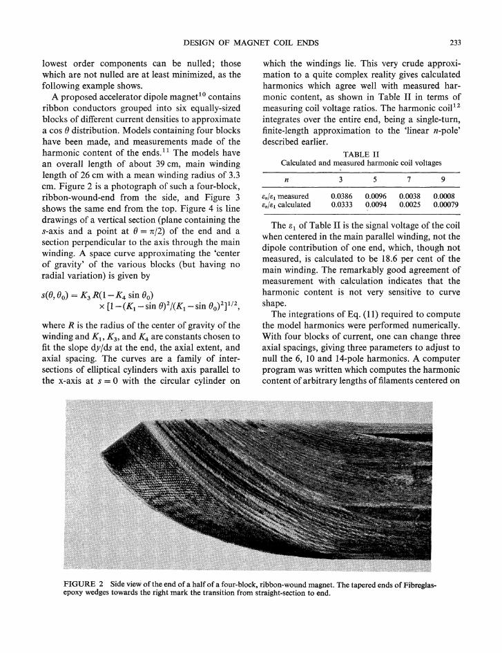
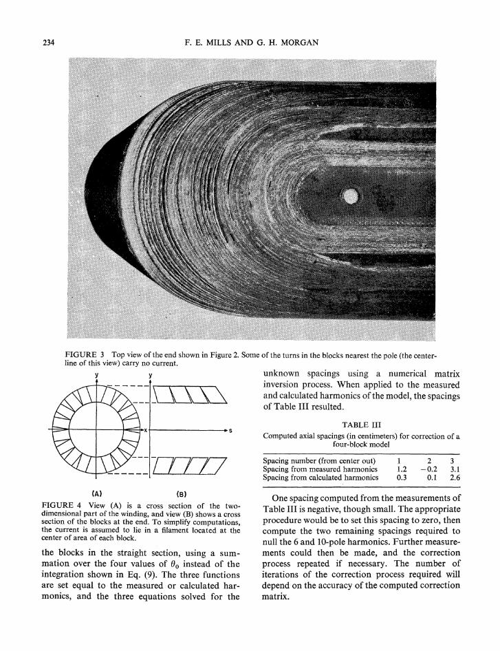
A proposed accelerator dipole magnet10 containsribbon conductors grouped into six equally-sizedblocks of different current densities to approximatea cos () distribution. Models containing four blockshave been made, and measurements made of theharmonic content of the ends. 11 The models havean overall length of about 39 em, main windinglength of 26 em with a mean winding radius of 3.3em. Figure 2 is a photograph of such a four-block,ribbon-wound-end from the side, and Figure 3shows the same end from the top. Figure 4 is linedrawings of a vertical section (plane containing thes-axis and a point at () = n12) of the end and asection perpendicular to the axis through the mainwinding. A space curve approximating the 'centerof gravity' of the various blocks (but .having noradial variation) is given by
s((}, (}o) = K 3 R(I- K4 sin (}o)x [1- (K1 - sin (})2/(K1 - sin ( 0)2]1/2,
where R is the radius of the center of gravity of thewinding and K 1 , K 3 , and K4 are constants chosen tofit the slope dylds at the end, the axial extent, andaxial spacing. The curves are a family of intersections of elliptical cylinders with axis parallel tothe x-axis at s = 0 with the circular cylinder on
n
en!e1 measureden!e1 calculated
3 579
0.0386 0.0096 0.0038 0.00080.0333 0.0094 0.0025 0.00079
FIGURE 2 Side view of the end of a half of a four-block, ribbon-wound magnet. The tapered ends of Fibreglasepoxy wedges towards the right mark the transition from straight-section to end.
234 F. E. MILLS AND G. H. MORGAN
FIGURE 3 Top view of the end shown in Figure 2. Some of the turns in the blocks nearest the pole (the centerline of this view) carry no current.
TABLE III
Computed axial spacings (in centimeters) for correction of afour-block model
unknown spacings using a numerical matrixinversion process. When applied to the measuredand calculated harmonics of the model, the spacingsof Table III resulted.
y y
-t--:~+----f----l~~X+----------+ S
--- ITTT7 Spacing number (from center out)Spacing from measured harmonicsSpacing from calculated harmonics
11.20.3
2 3-0.2 3.1
0.1 2.6
FIGURE 4 View (A) is a cross section of the twodimensional part of the winding, and view (B) shows a crosssection of the blocks at the end. To simplify computations,the current is assumed to lie in a filament located at thecenter of area of each block.
the blocks in the straight section, using a summation over the four values of eo instead of theintegration shown in Eq. (9). The three functionsare set equal to the measured or calculated harmonics, and the three equations solved for the
CA} CB) One spacing computed from the measurements ofTable III is negative, though small. The appropriateprocedure would be to set this spacing to zero, thencompute the two remaining spacings required tonull the 6 and IO-pole harmonics. Further measurements could then be made, and the correctionprocess repeated if necessary. The number ofiterations of the correction process required willdepend on the accuracy of the computed correctionmatrix.
DESIGN OF MAGNET COIL ENDS 235
REFERENCES
1. K. Robinson and G. R. Lambertson, private communications.
2. R. B. Meuser, IEEE Trans. Nucl. Sci. NS-18, No.3, 677(1971).
3. M. A. Green, Lawrence Berkeley Laboratory Engineering Note VCID 3492 (1970)..
4. J. H. Coupland, Rutherford High Energy LaboratoryReport RHEL/R 203 (1970).
5. A similar procedure was followed by R. A. Beth [BNLAccelerator Dept. Informal Report RAB-8 (1963)] inconnection with long coil field measurements.
6. J. H. Jeans, The Mathematica' Theory of Electricity andMagnetism (Cambridge University Press, 1938).
7. B. Hague, Principles of Electromagnetism Applied toElectrical Machines (Dover Publications, 1962).
8. R. A. Beth, J. Appl. Phys., 40, 4782 (1969).9. K. Halbach, Nucl. Instr. and Methods, 78, 185 (1970).
10. 200-GeV Intersecting Storage Accelerators, ISABELLE,A Preliminary Design Study, BNL Informal Report16716 (1972).
11. W. B. Sampson, P. F. Dahl, A. D. McInturff, and G. H.Morgan, Proc. Fourth Int. Con! on Magnet Technology,Brookhaven National Laboratory, 1972 (USAEC CONF720908), p. 752.
12. G. H. Morgan, Ref. 11, p. 787.
Received 3 April 1973
Related Documents