A Flexible Wideband Millimeter-Wave Channel Sounder with Local Area and NLOS to LOS Transition Measurements IEEE International Conference on Communications (ICC) Paris, France, May 21-25, 2017 George R. MacCartney Jr., Hangsong Yan, Shu Sun, and Theodore S. Rappaport {gmac,hy942,ss7152,tsr}@nyu.edu 2017 NYU WIRELESS G. R. MacCartney, Jr., H. Yan, S. Sun, and T. S. Rappaport, “A Flexible Wideband Millimeter-Wave Channel Sounder with Local Area and NLOS to LOS Transition Measurements,” in 2017 IEEE International Conference on Communications (ICC) Paris, France, May 2017, pp. 1-7.

Welcome message from author
This document is posted to help you gain knowledge. Please leave a comment to let me know what you think about it! Share it to your friends and learn new things together.
Transcript

A Flexible Wideband Millimeter-Wave Channel
Sounder with Local Area and NLOS to LOS
Transition Measurements
IEEE International Conference on Communications (ICC)
Paris, France, May 21-25, 2017
George R. MacCartney Jr., Hangsong Yan, Shu Sun, and Theodore S. Rappaport
{gmac,hy942,ss7152,tsr}@nyu.edu
2017 NYU WIRELESSG. R. MacCartney, Jr., H. Yan, S. Sun, and T. S. Rappaport, “A Flexible
Wideband Millimeter-Wave Channel Sounder with Local Area and NLOS
to LOS Transition Measurements,” in 2017 IEEE International
Conference on Communications (ICC) Paris, France, May 2017, pp. 1-7.

2
Agenda
Background, Motivation, and Challenges
CmWave and MmWave Channel Sounders in the Literature
New Dual-Mode NYU Channel Sounder
Measurement System Hardware and Calibration
LOS to NLOS Transition and Local Area Measurements and Results
Conclusions and Noteworthy Observations

3
Background
TX antenna(s) with a sectored or is quasi-
omnidirectional pattern
User Equipment (UE) or RX employs multiple
omnidirectional antennas (typically dipoles or
patches)
Multiple RF chains at TX and/or RX or electronic
switching between elements
Sophisticated post-processing algorithms to de-
embed antenna patterns and to temporally and
spatially resolve multipath components (MPCs):
RiMAX; ESPRIT; SAGE; MUSIC
Less than one second to record multiple
channel snapshots (long-term synchronization
not a requirement for excess delay)
How do traditional channel sounders work at sub-6 GHz?
Elektrobit PropsoundTM Channel Sounder: IST-4-027756 WINNER II, “WINNER II channel models,”
European Commission, IST-WINNER, D1.1.2 V1.2, Sept. 2007. [Online]. Available:
http://projects.celticinitiative.org/winner+/WINNER2-Deliverables/
Elektrobit PropsoundTM

4
Motivation
Free space path loss (FSPL) much greater in first meter of propagation:~30 dB / 36 dB more attenuation at 30 GHz / 60 GHz compared to 1 GHz
Directional horn antennas provide gain at TX/RX Benefits:
1. Increased link margin2. Spatial filtering / resolution3. Extraction of environment features and
characteristics for ray-tracing and site-planning
Downsides:1. 0.5-4 hours for full TX/RX antenna sweeps2. Lack of synchronization and channel
dynamics between measurements captured at different angles
3. RF front-ends and components are expensive, fragile, and costly
Why a new channel sounder methodology at mmWave?
NYU Channel SounderHorn antennas

5
Channel Sounder Requirements
Measure path loss at long-range distances (100’s of meters)
Ultra-Wideband signal (≥ 1 GHz bandwidth) with nanosecond MPC
resolution
Angular/spatial resolution for AOD and AOA modeling
Real-time measurements to capture small-scale temporal dynamics
greater than the Doppler rate of the channel and rapidly fading
blockage scenarios
Synchronized measurements between TX and RX for accurate time of
flight / true propagation delay and for synthesizing omnidirectional
PDPs
Requirements for mmWave channel modeling given new
measurement methodology

6
Types of Channel Sounders
[29] G. R. MacCartney, Jr. and T. S. Rappaport, “A flexible millimeter-wave channel sounder with absolute timing,” IEEE Journal on Selected Areas in
Communications, 2017, June 2017.
Direct RF pulse systems: repetitive short probing pulse w/ envelope
detection
VNA: measures S21 parameter via IDFT
Sliding correlator: exploits a constant envelope signal for max power
efficiency; low bandwidth ADC.
OFDM/FFT/Other types: direct-correlation / real-time with wideband ADC
acquisition; thousands of PDPs/CIRs per second
New NYU channel sounder with two modes: sliding correlator and real-
time correlation (32 microsecond sampling interval). See [29] for more
info.

7
NYU Dual Mode Channel Sounder Architectures
Sliding Correlator Analog correlation with RX chip rate slightly offset from TX rate: 499.9375 Mcps
(slide factor of 8,000: 39 dB processing gain)
Period of time-dilated PDP allows much lower ADC sampling rate:
o 2047 ×1
500 MHz−499.9375 MHz=
2047
62.5 kHz= 32.752 ms
Default averaging of 20 PDPs to improve SNR: 655 ms
Real-time spread spectrum (direct-correlation) Sample raw I and Q baseband channels with high-speed ADC (1.5 GS/s on each
channel): 𝑦 𝑡 = ℎ 𝑡 ∗ 𝑥 𝑡 ⇔ 𝑌 𝑓 = 𝐻(𝑓) ∙ 𝑋(𝑓) FFT, matched filter, and IFFT performed on periodic complex received waveform:
ℎ 𝑡 = 𝐈𝐅𝐅𝐓𝐅𝐅𝐓 𝒚(𝒕)
𝐅𝐅𝐓 𝒙(𝒕)
Minimum periodic PDP snapshot of 32.753 μs (30,500 PDPs per second). Memory
for up to 41,000 consecutive PDPs
Two Architectures for Channel Sounder RX
[29] G. R. MacCartney, Jr. and T. S. Rappaport, “A flexible millimeter-wave channel sounder with
absolute timing,” IEEE Journal on Selected Areas in Communications, June 2017.

8
TX Baseband Signal for Dual Mode Channel Sounder
Variable length and repetitive PN codes
Default length: 211-1=2047 chips
Up to 500 Mcps (1 GHz RF bandwidth)
Extremely long codes when memory is limited
Integration with LabVIEW-FPGA and FlexRIO
Adapter Modules (FAM)
DAC clocked at 125 MHz (8 ns SCTL) with 16
time-interleaved channels (SerDes) for 2 GS/s
rates
Flexible digital triggers along chassis backplane
assist synchronization
FPGA Digital Logic and Triggers
LabVIEW-FPGA
[29] G. R. MacCartney, Jr. and T. S. Rappaport, “A flexible millimeter-wave channel sounder with absolute
timing,” IEEE Journal on Selected Areas in Communications, June 2017.

9
NYU Channel Sounder TX
[29] G. R. MacCartney, Jr. and T. S. Rappaport, “A flexible millimeter-wave channel sounder with absolute
timing,” IEEE Journal on Selected Areas in Communications, June 2017.

10
NYU Channel Sounder RX – Sliding Correlator
4 samples per chip: 1999.75 MS/s
4samples
chip
= 499.9375 Mcps
[29] G. R. MacCartney, Jr. and T. S. Rappaport, “A flexible millimeter-wave channel sounder with absolute
timing,” IEEE Journal on Selected Areas in Communications, June 2017.

11
NYU Channel Sounder RX – Direct Correlation
[29] G. R. MacCartney, Jr. and T. S. Rappaport, “A flexible millimeter-wave channel sounder with absolute
timing,” IEEE Journal on Selected Areas in Communications, June 2017.

12
Antenna Control and Software Functionality
TX/RX antenna control via FLIR Pan-Tilt D100 gimbal w/ game controller
Automatic azimuth sweeps for AOD/AOA
Automatic linear track translations for small-scale measurements
Real-time feedback of channel with PDP and azimuth power spectra display
Rubidium (Rb) references at TX/RX for time/frequency synchronization
Ad hoc WiFi control of TX antenna from RX system (50 to 75m)
Linear track
FLIR Gimbal

13
True Propagation Delay Calibration
Indoor and Outdoor (Tetherless) Methods for Drift Calibration
[29] G. R. MacCartney, Jr. and T. S. Rappaport, “A flexible millimeter-wave channel sounder with absolute
timing,” IEEE Journal on Selected Areas in Communications, June 2017.
14
LOS to NLOS Transition
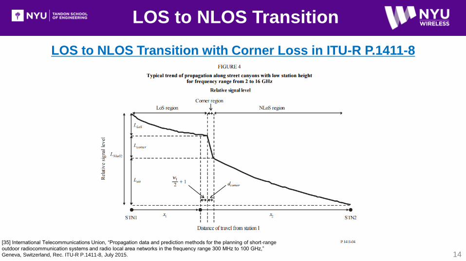
LOS to NLOS Transition with Corner Loss in ITU-R P.1411-8
[35] International Telecommunications Union, “Propagation data and prediction methods for the planning of short-range
outdoor radiocommunication systems and radio local area networks in the frequency range 300 MHz to 100 GHz,”
Geneva, Switzerland, Rec. ITU-R P.1411-8, July 2015.

15
LOS to NLOS Transition Measurements with Sliding Correlator Mode
LOS to NLOS Transition 5 LOS: 29.6 m to 49.1 m (Euclidean)
11 NLOS: 50.8 m to 81.6 m (Euclidean)
Bridge street width: 18 m
10 story buildings
RX locations in 5 m adjacent increments to
form an “L”-shaped route
TX antenna HPBW:7º/7º Az/El
RX antenna HPBW:15º/15º Az/El
TX Az/El antenna pointing angles remained
fixed at 100º/0º
RX El fixed at 0º for all locations
RX azimuth sweeps in HPBW increments with
starting position at strongest angle of arrival
TX/RX antenna heights at 4 m / 1.5 m
5 repeated sweeps at each location for
temporal variations

16
LOS to NLOS Transition Results
Omnidirectional path loss synthesized from
azimuth sweeps at each location [32]
RX92 to RX87 half-way down urban
canyon results in ~25 dB attenuation
(path distance of 25 meters)
When moving around corner:
Vehicle speed of 35 m/s will experience
35 dB/s fading rate
Mobile at a walking speed of 1 m/s will
experience 1 dB/s fading rate
LOS PLE higher than free space due to
coarse antenna boresight alignment
[32] S. Sun et al., “Synthesizing omnidirectional antenna patterns, received power and path loss from
directional antennas for 5G millimeter-wave communications,” in IEEE Global Communications
Conference (GLOBECOM), Dec. 2015, pp. 1–7.

17
LOS to NLOS Transition Results
LOS NLOS

18
Local Area Cluster Measurements / with Sliding Correlator Mode
LOS and NLOS Local Area
Omnidirectional path loss synthesized from
azimuth sweeps at each location [32]
5 LOS: 57.8 m to 70.6 m (Euclidean)
5 NLOS: 61.7 m to 73.7 m (Euclidean)
RX locations for LOS and NLOS are placed in 5 m
adjacent increments that form a semi-circle
Local area grid approximately 5 m x 10 m
Measurement
Set
LOS: RX61 to RX65 NLOS: RX51 to
RX55
Omnidirectional
Received Power
STD
4.3 dB 2.2 dB
Min/Max Omni
Path Loss [dB]
105.1 dB / 114.7 dB 134.04 dB / 139.3 dB
Avg. Omni Path
Loss [dB]
111 dB 137 dB
[32] S. Sun et al., “Synthesizing omnidirectional antenna patterns, received power and path loss
from directional antennas for 5G millimeter-wave communications,” in IEEE Global
Communications Conference (GLOBECOM), Dec. 2015, pp. 1–7.

Conclusions and Observations
19
New NYU dual-mode mmWave channel sounder with sliding correlator and real-time
spread spectrum capabilities:
Long-distance (100’s of meters) and large-scale path loss measurements
Accurate AOD and AOA angular spreads in azimuth and elevation
Capture dynamic channel fades over short intervals in large crowds
LOS to NLOS transition measurements along a route using sliding correlator
Results show significant corner loss of 25 dB over a 25 m path from LOS to NLOS
Two main spatial lobes at RX in LOS for a single TX pointing direction
LOS and NLOS local area cluster measurements using sliding correlator
Relatively low standard deviation in received power for LOS RX locations in a 5 m x 10 m
grid: 4.3 dB
Low standard deviation in received power for NLOS RX locations in a 5 x 10 m grid: 2.2 dB
20
NYU WIRELESS Industrial Affiliates
Acknowledgement to our NYU WIRELESS Industrial Affiliates and NSF:

21
References
[1] Z. Pi and F. Khan, “An introduction to millimeter-wave mobile broadband systems,” IEEE Communications Magazine, vol. 49, no. 6, pp. 101–107, June 2011.
[2] F. Boccardi et al., “Five disruptive technology directions for 5G,” IEEE Communications Magazine, vol. 52, no. 2, pp. 74–80, Feb. 2014.
[3] T. S. Rappaport, W. Roh, and K. Cheun, “Mobile’s millimeter-wave makeover,” in IEEE Spectrum, vol. 51, no. 9, Sept. 2014, pp. 34–58.
[4] Federal Communications Commission, “Spectrum Frontiers R&O and FNPRM: FCC16-89,” July. 2016. [Online]. Available: https://apps.fcc.gov/edocs
public/attachmatch/FCC-16-89A1 Rcd.pdf
[5] 3GPP, “Technical specification group radio access network; channel model for frequency spectrum above 6 GHz (Release 14),” 3rd Generation Partnership
Project (3GPP), TR 38.900 V14.2.0, Dec. 2016. [Online]. Available: http://www.3gpp.org/DynaReport/38900.htm
[6] W. G. Newhall, T. S. Rappaport, and D. G. Sweeney, “A spread spectrum sliding correlator system for propagation measurements,” in RF Design, Apr. 1996,
pp. 40–54.
[7] W. G. Newhall, K. Saldanha, and T. S. Rappaport, “Using RF channel sounding measurements to determine delay spread and path loss,” in RF Design, Jan.
1996, pp. 82–88.
[8] W. G. Newhall and T. S. Rappaport, “An antenna pattern measurement technique using wideband channel profiles to resolve multipath signal components,” in
Antenna Measurement Techniques Association 19th Annual Meeting & Symposium, Nov. 1997, pp. 17–21.
[9] Aalto University, AT&T, BUPT, CMCC, Ericsson, Huawei, Intel, KT Corporation, Nokia, NTT DOCOMO, New York University, Qualcomm, Samsung,
University of Bristol, and University of Southern California, “5G channel model for bands up to 100 GHz,” 2016, Oct. 21. [Online]. Available:
http://www.5gworkshops.com/5GCM.html
[10] K. Haneda et al., “5G 3GPP-like channel models for outdoor urban microcellular and macrocellular environments,” in 2016 IEEE 83rd Vehicular Technology
Conference (VTC2016-Spring), May 2016, pp. 1–7.
[11] ] K. Haneda et al., “Indoor 5G 3GPP-like channel models for office and shopping mall environments,” in 2016 IEEE International Conference on
Communications Workshops (ICCW), May 2016, pp. 694–699.
[12] S. Sun et al., “Investigation of prediction accuracy, sensitivity, and parameter stability of large-scale propagation path loss models for 5G wireless
communications (Invited Paper),” IEEE Transactions on Vehicular Technology, vol. 65, no. 5, pp. 2843–2860, May 2016.
[13] G. R. MacCartney, Jr. et al., “Indoor office wideband millimeter-wave propagation measurements and models at 28 GHz and 73 GHz for ultradense 5G
wireless networks (Invited Paper),” IEEE Access, pp. 2388–2424, Oct. 2015.
[14] T. S. Rappaport et al., “Wideband millimeter-wave propagation measurements and channel models for future wireless communication system design (Invited
Paper),” IEEE Transactions on Communications, vol. 63, no. 9, pp. 3029–3056, Sept. 2015.

22
References
[15] IST-4-027756 WINNER II, “WINNER II channel models,” European Commission, IST-WINNER, D1.1.2 V1.2, Sept. 2007. [Online]. Available:
http://projects.celticinitiative.org/winner+/WINNER2-Deliverables/
[16] 3GPP, “Technical specification group radio access network; study on 3D channel model for LTE (Release 12),” 3rd Generation Partnership
Project (3GPP), TR 36.873 V12.2.0, June 2015. [Online]. Available: http://www.3gpp.org/dynareport/36873.htm
[17] B. Thoma, T. S. Rappaport, and M. D. Kietz, “Simulation of bit error performance and outage probability of /4 DQPSK in frequency-selective indoor radio
channels using a measurement-based channel model,” in IEEE Global Telecommunications Conference (GLOBECOM). Communication for Global Users, vol. 3,
Dec 1992, pp. 1825–1829.
[18] T. S. Rappaport, Wireless Communications: Principles and Practice, 2nd ed. Upper Saddle River, NJ: Prentice Hall, 2002, ch. 4, 5.
[19] P. B. Papazian et al., “A radio channel sounder for mobile millimeter-wave communications: System implementation and measurement assessment,” IEEE
Transactions on Microwave Theory and Techniques, vol. 64, no. 9, pp. 2924–2932, Sept. 2016.
[20] S. Salous et al., “Wideband MIMO channel sounder for radio measurements in the 60 GHz band,” IEEE Transactions on Wireless Communications, vol. 15, no.
4, pp. 2825–2832, Apr. 2016.
[21] Z. Wen et al., “mmWave channel sounder based on COTS instruments for 5G and indoor channel measurement,” in 2016 IEEE Wireless Communications and
Networking Conference, Apr. 2016, pp. 1–7.
[22] J. J. Park et al., “Millimeter-wave channel model parameters for urban microcellular environment based on 28 and 38 GHz measurements,” in 2016 IEEE 27th
Annual International Symposium on Personal, Indoor, and Mobile Radio Communications (PIMRC), Sept. 2016, pp. 1–5.
[23] E. Ben-Dor et al., “Millimeter-wave 60 GHz outdoor and vehicle AOA propagation measurements using a broadband channel sounder,” in 2011 IEEE Global
Telecommunications Conference (GLOBECOM), Dec. 2011, pp. 1–6.
[24] D. Cox, “Delay doppler characteristics of multipath propagation at 910 MHz in a suburban mobile radio environment,” IEEE Transactions on Antennas and
Propagation, vol. 20, no. 5, pp. 625–635, Sept. 1972.
[25] C. Chu, P. P. Chu, and R. E. Jones, “Design techniques of FPGA based random number generator,” in Military and Aerospace Applications of Programmable
Devices and Technology Conference. Hopkins University Applied Physics Laboratory, Sept. 1999.
[26] T. S. Rappaport et al., “Millimeter Wave Mobile Communications for 5G Cellular: It Will Work!” IEEE Access, vol. 1, pp. 335–349, May 2013.
[27] S. Nie et al., “72 GHz millimeter wave indoor measurements for wireless and backhaul communications,” in 2013 IEEE 24th International Symposium on
Personal Indoor and Mobile Radio Communications (PIMRC), Sept. 2013, pp. 2429–2433.
[28] G. R. MacCartney, Jr. and T. S. Rappaport, “73 GHz millimeter wave propagation measurements for outdoor urban mobile and backhaul communications in
New York City,” in 2014 IEEE International Conference on Communications (ICC), June 2014, pp. 4862–4867.

23
References
[29] G. R. MacCartney, Jr. and T. S. Rappaport, “A flexible millimeter-wave channel sounder with absolute timing,” IEEE Journal on Selected Areas in
Communications, June 2017.
[30] M. I. Skolnik, Introduction to Radar Systems, 3rd ed. New York, NY, USA: McGRAW-HILL, 2001.
[31] G. R. MacCartney, Jr., M. K. Samimi, and T. S. Rappaport, “Omnidirectional path loss models in New York City at 28 GHz and 73 GHz,” in IEEE 25th
International Symposium on Personal Indoor and Mobile Radio Communications (PIMRC), Sept. 2014, pp. 227–331.
[32] S. Sun et al., “Synthesizing omnidirectional antenna patterns, received power and path loss from directional antennas for 5G millimeter-wave communications,”
in IEEE Global Communications Conference (GLOBECOM), Dec. 2015, pp. 1–7.
[33] M. K. Samimi et al., “28 GHz angle of arrival and angle of departure analysis for outdoor cellular communications using steerable beam antennas in New York
City,” in 2013 IEEE 77th Vehicular Technology Conference (VTC-Spring), June 2013, pp. 1–6.
[34] S. Sun et al., “Millimeter wave small-scale spatial statistics in an urban microcell scenario,” in 2017 IEEE International Conference on Communications (ICC),
May 2017, pp. 1–7.
[35] International Telecommunications Union, “Propagation data and prediction methods for the planning of short-range outdoor radiocommunication systems and
radio local area networks in the frequency range 300 MHz to 100 GHz,” Geneva, Switzerland, Rec. ITU-R P.1411-8, July 2015.

Thank You!
24
Questions
Related Documents