International Journal of Fracture 56: 209-231, 1992. © 1992 Kluwer Academic Publishers. Printed in the Netherlands. 209 A finite element analysis of dynamic fracture initiation by ductile failure mechanisms in a 4340 steel M. JHA 1 and R. NARASIMHAN 2 i Warhead Group, ARDE, Pune 411021, India; 2 Mechanical Engineerin9 Department, IISc Bangalore 560012, India Received 1 July 1990; accepted in revised form 30 October 1991 Abstract. In some recent dropweight impact experiments [5] with pre-notched bend specimens of 4340 steel, it was observed that considerable crack tunneling occurred in the interior of the specimen prior to gross fracture initiation on the free surfaces. The final failure of the side ligaments happened because of shear lip formation. The tunneled region is characterized by a flat, fibrous fracture surface. In this paper, the experiments of [5] (corresponding to 5 m/s impact speed) are analyzed using a plane strain, dynamic finite element procedure. The Gurson constitutive model that accounts for the ductile failure mechanisms of micro-void nucleation, growth and coalescence is employed. The time at which incipient failure was observed near the notch tip in this computation, and the value of the dynamic J-integral, Jn, at this time, compare reasonably well with experiments.This investigation shows that J-controlled stress and deformation fields are established near the notch tip whenever Jd increases with time. Also, it is found that the evolution of micro-mechanical quantities near the notch root can be correlated with the time variation of J,~. The strain rate and the adiabatic temperature rise experienced at the notch root are examined. Finally, spatial variations of stresses and deformations are analyzed in detail. I. Introduction Dynamic fracture initiation occurs under rapidly varying loads such as that produced by impact or explosive detonation. In such situations, the loading rates (measured in terms of the stress intensity rate /() are much higher (more than 104 times) than in a conventional quasi-static fracture test [1]. For many metallic materials, the dynamic fracture toughness Kid depends strongly on /( (see, for example, the experimental results given in [2, 3]). There are several factors that can influence the functional dependence of Kid on /£ [2-4]. These include rate sensitivity, adiabatic heating near the crack tip, and most importantly, the dominant failure mechanism. Dynamic fracture can occur on the micro-scale by nucleation, growth and coalescence of voids (ductile failure) or due to coalescence of planar micro cracks (brittle failure) [I]. In a recent study, Zehnder et al. [5] have performed drop-weight impact tests with three-point bend specimens of 4340 steel. The specimens used in these experiments were 1 cm thick and impact speeds of 5 m/s and 10 m/s were employed. The fracture surface of the broken specimens (see photograph Fig. 9 in [5]) shows that considerable crack tunneling occurs in the interior of the specimen prior to gross fracture initiation on the free surfaces. The final failure of the side ligaments (portion between the tunneled core and the free surfaces) happens because of formation of shear lips which are inclined at 45 ° to the free surfaces. The tunneled region is a fibrous, flat-fracture zone near the center-plane of the specimen, which has the shape of a thumb-nail and is about 0.6 cm in length. It is characterized by the ductile failure mechanisms of micro-void nucleation and growth. Based on optical measure- ments near the crack tip, Zehnder et al. [5] have estimated the times at which tunneling and gross fracture initiation (on the free surfaces) occurred in their experiments. For an impact test

Welcome message from author
This document is posted to help you gain knowledge. Please leave a comment to let me know what you think about it! Share it to your friends and learn new things together.
Transcript
International Journal of Fracture 56: 209-231, 1992. © 1992 Kluwer Academic Publishers. Printed in the Netherlands. 209
A finite element analysis of dynamic fracture initiation by ductile failure mechanisms in a 4340 steel
M. JHA 1 and R. N A R A S I M H A N 2 i Warhead Group, ARDE, Pune 411021, India; 2 Mechanical Engineerin 9 Department, IISc Bangalore 560012,
India
Received 1 July 1990; accepted in revised form 30 October 1991
Abstract. In some recent dropweight impact experiments [5] with pre-notched bend specimens of 4340 steel, it was observed that considerable crack tunneling occurred in the interior of the specimen prior to gross fracture initiation on the free surfaces. The final failure of the side ligaments happened because of shear lip formation. The tunneled region is characterized by a flat, fibrous fracture surface. In this paper, the experiments of [5] (corresponding to 5 m/s impact speed) are analyzed using a plane strain, dynamic finite element procedure. The Gurson constitutive model that accounts for the ductile failure mechanisms of micro-void nucleation, growth and coalescence is employed. The time at which incipient failure was observed near the notch tip in this computation, and the value of the dynamic J-integral, Jn, at this time, compare reasonably well with experiments. This investigation shows that J-controlled stress and deformation fields are established near the notch tip whenever Jd increases with time. Also, it is found that the evolution of micro-mechanical quantities near the notch root can be correlated with the time variation of J,~. The strain rate and the adiabatic temperature rise experienced at the notch root are examined. Finally, spatial variations of stresses and deformations are analyzed in detail.
I. Introduction
Dynamic fracture initiation occurs under rapidly varying loads such as that produced by impact or explosive detonation. In such situations, the loading rates (measured in terms of the stress intensity rate /() are much higher (more than 104 times) than in a conventional quasi-static
fracture test [1]. For many metallic materials, the dynamic fracture toughness Kid depends
strongly on /( (see, for example, the experimental results given in [2, 3]). There are several factors that can influence the functional dependence of Kid on /£ [2-4]. These include rate sensitivity, adiabatic heating near the crack tip, and most importantly, the dominant failure
mechanism. Dynamic fracture can occur on the micro-scale by nucleation, growth and coalescence of voids (ductile failure) or due to coalescence of planar micro cracks (brittle failure)
[I]. In a recent study, Zehnder et al. [5] have performed drop-weight impact tests with three-point
bend specimens of 4340 steel. The specimens used in these experiments were 1 cm thick and impact speeds of 5 m/s and 10 m/s were employed. The fracture surface of the broken specimens (see photograph Fig. 9 in [5]) shows that considerable crack tunneling occurs in the interior of
the specimen prior to gross fracture initiation on the free surfaces. The final failure of the side ligaments (portion between the tunneled core and the free surfaces) happens because of formation of shear lips which are inclined at 45 ° to the free surfaces.
The tunneled region is a fibrous, flat-fracture zone near the center-plane of the specimen, which has the shape of a thumb-nail and is about 0.6 cm in length. It is characterized by the ductile failure mechanisms of micro-void nucleation and growth. Based on optical measure- ments near the crack tip, Zehnder et al. [5] have estimated the times at which tunneling and gross fracture initiation (on the free surfaces) occurred in their experiments. For an impact test
210 M. Jha and R. Narasimhan
(with speed of 5 m/s) using a specimen with a machined crack tip, they have reported that tunneling occurred between 400 to 500 txs. On the other hand, gross fracture initiation on the free surfaces was observed in the above test only between 600 to 700 las [5]. In earlier static experiments conducted by Zehnder and Rosakis 1-6] using the same specimen geometry, material and heat treatment, qualitatively similar observations were made regarding crack tunneling.
In this paper, the experiments of Zehnder et al. 1-5] (corresponding to 5 m/s impact speed) are analyzed using a 2-D plane strain, transient finite element procedure. A notched three point bend specimen having the same geometry and material properties as in the experiments is considered. The main objective is to simulate fibrous fracture initiation under transient loading and to compare with the experimental observations of [5]. For this purpose, an elastic-plastic damage accumulation model, proposed by Gurson l-7-9], that accounts for micro-void nucleation, growth and coalescence is employed in the present computations. An important feature of this material model is that a failure criterion is directly incorporated in it which causes the material stress carrying capacity to vanish locally at a point when the volume fraction of voids reaches a critical value [9]. The details pertaining to the model will be outlined in Section 2.
In an earlier work 1-10], a 3-D finite element analysis was performed using the Gurson model to study crack tunneling under quasi-static loading. This investigation demonstrated that the onset of ductile failure near the center-plane of the 3-D specimen may be accurately predicted using a 2-D plane strain analysis. In particular, it was observed in 1-10] that incipient damage near the crack tip in the center-plane of the 3-D specimen occurred at around the same local value of the J-integral as obtained in a plane strain calculation. Thus, although a 3-D dynamic analysis is not performed in the present work, it is expected that the plane strain calculation will predict the onset of fibrous fracture near the center-plane of the actual test specimen with reasonable accuracy.
Another important issue that is investigated in this paper is the influence of the dynamic J-integral Jd on the stresses and deformations near the notch tip. For dynamic loading, J must be evaluated on a contour which is shrunk on to the crack tip 1-11]. For materials obeying incremental plasticity theories, Jd is not equal to the energy release rate. However, it is still expected to serve as a measure of the intensity of the near-tip deformation fields, provided the loading to the crack tip region is monotonically increasing and the stress histories for material particles near the crack tip are nearly proportional 1-11]. Hence, it is of interest to examine whether a J-dominant field is established near the notch tip, particularly at the time of incipient material failure. Also, it is of relevance to investigate whether the evolution of micro-mechanical quantities such as the volume density of voids at the notch root is controlled by the time variation of Jd. A careful study of these issues is necessary to ascertain the precise role played by Jd during ductile fracture initiation under transient loading.
In recent years, several investigators have used damage accumulation models (like the Gurson model) to study ductile failure under various situations. These studies have focussed mainly on quasi-static conditions. A recent review of these investigations can be found in [12]. Tvergaard and Needleman I-9] analyzed cup-cone fracture in a round tensile bar. Aoki et al. [13] and Aravas and McMeeking [14] examined the interaction between a crack tip and a void. Becker et al. [15] analyzed ductile failure in AI-Li alloys due to crack growth along grain boundaries by nucleation and growth of micro-voids.
Dynamic fracture initiation 211
The above local approach to ductile failure has not found extensive application in dynamic fracture problems. Such an approach could provide the key to understanding important issues such as the micro-mechanics of dynamic fracture, and the observed dependence of the fracture toughness (of structural metals) on loading rate, temperature, etc. Costin and Duffy [3] proposed simple micro-structural models of both cleavage and ductile failure mechanisms to interpret their dynamic fracture toughness data for 1018 cold rolled steel which had been obtained over a range of temperatures. Norris [16] analyzed Charpy impact tests in ASTM A533 B steel specimens using a numerical procedure. He employed a J2 flow theory of plasticity and predicted damage near the notch root by using a criterion based on equivalent plastic strain. Tvergaard and Needleman [17] have recently performed a dynamic finite element analysis of the Charpy impact test to investigate ductile-brittle transition of high nitrogen steel.
2. Constitutive model
In this work, a (small strain) rate sensitive version of the Gurson model, which was introduced by Pan et al. [8] is employed. This is a continuum elastic-plastic model that accounts for void nucleation and growth. In his original, rate independent model, Gurson [7] proposed a yield function of the form ~(a~s, a,., f), which depends on the macroscopic (aggregate) stress ai~, the microscopic (matrix) tensile flow stress ~,., and the current void volume fraction f. Tvergaard and Needleman [9] modified the Gurson yield condition and suggested the following form:
. ( • (ai j , a . , , f ) = Z7 + 2 f * q , c o s n i ~ - - - i - (1 + ( q i f . ) z ) = o.
(Ira \ ,~a,, I (2.1)
In this equation, ae = (3/2SijSij) 1/2, where Sii is the stress deviator, represents the macroscopic equivalent stress.
Tvergaard [18] introduced the parameter q~ in (2.1), with a value of 1.5, to obtain better agreement between predictions of this model and numerical studies of periodic array of voids. Tvergaard and Needleman [9] proposed that a function f * ( f ) should be included in the yield condition to simulate the loss of stress carrying capacity associated with void coalescence. This function is defined as:
+ K ( f -- fc) f > f /
where K = (l/q1 - fc)/(fp - fc). Here, fc is the value of the void volume fraction at which void coalescence first occurs and f r is its value at final failure. From the yield condition (2.1), it can be observed that the material loses its stress carrying capacity, when f * ~ 1/ql. Thus, an essential feature of the model is that a failure criterion is directly built in to the constitutive equations. Based on experimental and numerical studies (see [19-21]), fc and fF are chosen as
212 M. Jha and R. Narasimhan
0.15 and 0.25, respectively. Further justification for the above choice of f r for AISI 4340 carbon steel is provided in Appendix A of [10].
In the rate sensitive version employed here, there is no explicit yield condition [8]. However, the function • serves as the flow potential, so that the plastic part of the macroscopic strain rate is expressed as:
g~ = ~ Oaij" (2.2)
Here, ~ is the rate of plastic flow. The rate sensitivity of the matrix material is represented by employing a power law relation for the matrix plastic strain rate ~ of the form:
• t/ a , . "~ 1/" g: = e o ~ ) • (2.3)
In the above equation, n is the strain rate hardening exponent, go is a reference strain rate and e~ is the current value of the matrix plastic strain. The function g(e~) represents the effective tensile flow stress of the matrix material in a tensile test carried out at a strain rate such that g~ = go. In this work, an isotropic power law hardening material with strain hardening exponent N is considered, so that:
g(s~) = ao~s ° + 1 . (2.4)
Here, tro is the initial yield stress and eo = tro/E, where E is the Young's modulus, is the initial yield strain.
The essential feature, representing the viscoplastic nature of the matrix material, in (2.3) is the dependence of g~ on only the current values of microscopic quantities (a,,, e~) and not on the rate 6"m. Herein, lies the difference between the rate independent [9-1 and rate dependent [8] models. However, in the limit as the strain rate exponent n ~ 0, the present rate sensitive material reduces exactly to the rate independent Gurson model, since the function g(e~) will then act effectively as flow strength of the matrix material, irrespective of strain rate. The 4340 steel considered in this work displays very little rate sensitivity (see, for example, [22]). Hence, a rate exponent of n = 0.001 is employed here to supress material rate effects. The study of rate sensitivity itself on dynamic fracture initiation will not be taken up in this paper.
The plastic parameter ~ in (2.2) is found by setting the macroscopic plastic work rate equal to the microscopic plastic dissipation, so that:
a o i ~ = (1 - f ) a m ~ . (2.5)
Using (2.2) in (2.5), ~ is found to be:
[ ae7 -~
L c~%1 " (2.6)
Dynamic fracture initiation 213
The void volume fraction f is allowed to evolve both due to growth of existing voids and
nucleation of new voids, so that,
f = fgrowth + f.uc~e,tio,. (2.7)
The growth law, which is described by,
fgrow,h = (1 -- f)e~k, (2.8)
is an outcome of the plastic incompressibility of the matrix material. It should, however, be noted that the macroscopic material response does not satisfy plastic incompressibility due to the existence of voids. A plastic strain controlled void nucleation law is assumed as [9]:
f.ude,tlon = d ~ , (2.9)
where d ( . ) is a function of the equivalent matrix plastic strain e~. The function d is chosen as [23]:
d - ~ e x p i - - (2.10) s.x/Zn L 2 \ s, } d
so that void nucleation follows a normal distribution about a mean nucleating strain e. with standard deviation s.. In the above equation, f . denotes the volume fraction of void nucleating particles. The values of f , , s, and s, are chosen as 0.04, 0.1 and 0.3, respectively. In Appendix A of [103, the basis for the above choice of parameters is discussed, with relevant comparisons to the micro-structural observations of Cox and Low [19] for AISI 4340 steel.
The constitutive equation for the material is written in rate form as:
~ i j = Ci jk l (~kl - - ~ l ) , (2.11)
where Cijk~ is the isotropic elasticity tensor. The evolution equation for the matrix flow stress a,, is obtained by enforcing the consistency condition (b = 0 at every stage of the deformation process, and by using (2.7) to (2.11).
3. Computational model and numerical procedure
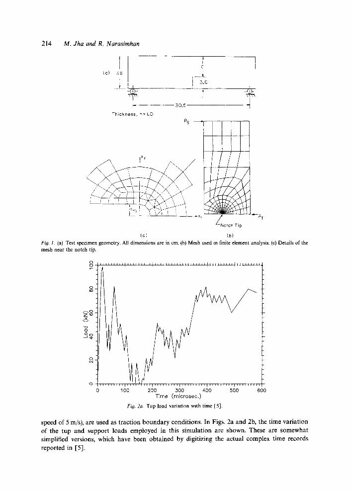
The notched three-point bend specimen that is considered in this investigation is shown in Fig. la. The initial notch diameter bo was taken as 0.03 cm, which is the same as that of the actual test specimen [5]. A 2-D (plane strain) finite element model of one half of the specimen is shown in Figs. lb and lc. The mesh is comprised of a total of 282 elements (which are mainly four-noded quadrilaterals with a few constant strain triangles), and 309 nodes. The smallest element size near the notch tip in this mesh is 0.0078 cm which is 0.26bo. The experimentally measured tup and support loads, given by Zehnder et al. [5] from their impact test (with impact
214 M. Jha and R. Narasimhan
c, I (o) _ ~ I
5.0 --cx-~
- - 3 0 . 5 J ]
Thickness, h=l.O PS
/ ""-- PT
Notch T~p
(b) (c) Fig. I. (a) Test specimen geometry. All dimensions are in cm. (b) Mesh used in finite element analysis. (c) Details of the mesh near the notch tip.
0 1 O0 200 300 400 500 600 Time (microsec. )
Fig. 2a. Tup load variation with time [5].
speed of 5 m/s), are used as traction boundary conditions. In Figs. 2a and 2b, the time variation of the tup and support loads employed in this simulation are shown. These are somewhat simplified versions, which have been obtained by digitizing the actual complex time records reported in [53.
Dynamic fracture initiation 215
0 0
0 O0
~ - - - . 0 Z ~ ,,¢
-(3 o
I l l I l l l i l [ L l l l l l t l l ~ l l l l l t i l ] l l l l l l l l l
t i l l i r t l l l t l l ~ l l l l ~ l i i i t ~ l t
0 100 200 300 Time (m i c rosec . )
400 500 600
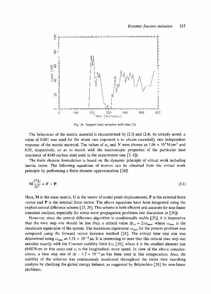
Fio. 2b. Support load variation with time [5].
The behaviour of the matrix material is characterized by (2.3) and (2.4). As already noted, a value of 0.001 was used for the strain rate exponent n to obtain essentially rate independent response of the matrix material. The values of ao and N were chosen as 1.06 × 10SN/cm 2 and 0.05, respectively, so as to match with the macroscopic properties of the particular heat treatment of 4340 carbon steel used in the experiments (see [5, 6]).
The finite element formulation is based on the dynamic principle of virtual work including inertia terms. The following equations of motion can be obtained from the virtual work principle by performing a finite element approximation [24]:
~2U M ~ y - = F - P . (3.1)
Here, M is the mass matrix, U is the vector of nodal point displacements, F is the external force vector and P is the internal force vector. The above equations have been integrated using the explicit central difference scheme [25, 26]. This scheme is both efficient and accurate for non-linear transient analysis, especially for stress wave propagation problems (see discussion in [26]).
However, since the central difference algorithm is conditionally stable [25], it is imperative that the time step size should be less than a critical value Atcr = 2/~o . . . . where (Dma x is the maximum eigenvalue of the system. The maximum eigenvalue Ogma x for the present problem was computed using the forward vector iteration method [24]. The critical time step size was determined using (Dma x as 1.31 × 10 -2 ps. It is interesting to note that this critical time step size matches exactly with the Courant stability limit h/cz [26], where h is the smallest element size (0.0078 cm in this case) and c~ is the longitudinal wave speed. In view of the above consider- ations, a time step size of At = 1.2 × 10 -2 ~ts has been used in this computation. Also, the stability of the solution was continuously monitored throughout the entire time marching analysis by checking the global energy balance, as suggested by Belytschko [26] for non-linear problems.
216 M. Jha and R. Narasimhan
The integration of the rate constitutive equations has been performed by using the rate tangent modulus method of Pierce et al. [27]. In this method, the effective plastic strain increment Ae~ between time t and t + At is expressed using a linear interpolation within this time increment. A Taylor series expansion is employed to estimate ~ at t + At. The expression for the resulting rate tangent moduli may be found in [27].
As noted in Section 2, complete loss of material stress carrying capacity occurs when f * = 1/ql (or equivalently when f = fF), leading to local failure. This implies that the material separates completely at this point and a traction-free surface develops. The failure criterion is implemented in the present computation following the method suggested in [28, 14]. In this method, the evolution of am and f are frozen after f reaches a value of 0.95fF. The macroscopic response is then elastic-perfectly plastic with a small pressure dependent yield stress. As pointed out in [14], the condition f = 0.95fF is used instead of f = fv, because as f approaches fF, the macroscopic equivalent stress aeqv approaches zero, causing numerical difficulties. An alternate element vanishing technique has been proposed by Tvergaard [28] to model the failure criterion.
A plane strain, dynamic analysis of the transient loading of the three-point bend specimen has been carried out using the procedure outlined above. At each time step, the dynamic J-integral, Jd(t) was computed using the domain integral formulation of Nakamura et al. [29, 1 i]. The computations were continued till the element nearest to the notch tip exhibited local material failure. This occurred at a time of tf .~ 550 p.s. The results obtained from the computation are analyzed in the following section.
4. Results and discussion
As mentioned in the introduction, one of the objectives of this work is to simulate fibrous fracture initiation under dynamic loading and to compare with the experimental observations of Zehnder et al. [5]. It should be noted that the 2-D plane strain analysis carried out here can at best model the onset of fibrous fracture near the center-plane of an actual test specimen. A 3-D dynamic analysis would be required to provide a complete understanding of the further development of the tunneled surface, as observed in the experiments of I-5]. Also, this investigation attempts to characterize the precise role played by Jd during the ductile failure process near the notch root. With the above objectives in perspective, time histories and spatial variations of field quantities are analyzed below.
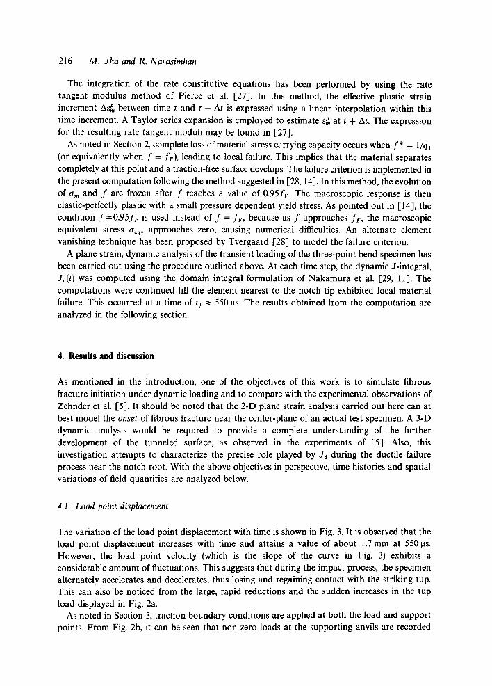
4.1. Load point displacement
The variation of the load point displacement with time is shown in Fig. 3. It is observed that the load point displacement increases with time and attains a value of about 1.7 mm at 550 tas. However, the load point velocity (which is the slope of the curve in Fig. 3) exhibits a considerable amount of fluctuations. This suggests that during the impact process, the specimen alternately accelerates and decelerates, thus losing and regaining contact with the striking tup. This can also be noticed from the large, rapid reductions and the sudden increases in the tup load displayed in Fig. 2a.
As noted in Section 3, traction boundary conditions are applied at both the load and support points. From Fig. 2b, it can be seen that non-zero loads at the supporting anvils are recorded
Dynamic fracture initiation 217
0 04
LO
E E
0
© o u
m EL 60
LO
d
0
0
i i i i i l l l l l l l l l l l l l l i l l t l l l l l ] l l l i l l l l l l l l l l [ l l l i l l ] l l l [ l I[
Y I ~ l l l l l l J l l l l t l l F I l l l l l l l t l l t l l l [ l l l i l l l l [ l l F F I I I I I I L I I I I I 0 100 200 300 400 500 600
Time (microsec.)
Fig. 3. Load point displacement versus time.
only after a rather large time of 180 ~ts. Similar observations have been made earlier by B6hme and Kalthoff [30] in their impact experiments using bend specimens. They have further noted that the effective information time t; in these experiments is the time taken for the transverse stress waves to travel from the point of impact through the specimen to the anvils. Their experimental results (see [30]) show that the specimen ends displace away from the supporting anvils (i.e. lose contact with the anvils) at a time of t = ti. They regain contact with the anvils at a time when non-zero support loads are first recorded. Indeed, by examining the displacement of the specimen ends, obtained from the present computation, it could be observed that the specimen ends lose contact with the supports between about 45 ~s and 160 p.s. The former is in approximate agreement with the information time ti (which is 53 Its for the present specimen), while the latter is close to the time when non-zero support loads were first measured in the experiments of [5].
4.2. Specimen energy
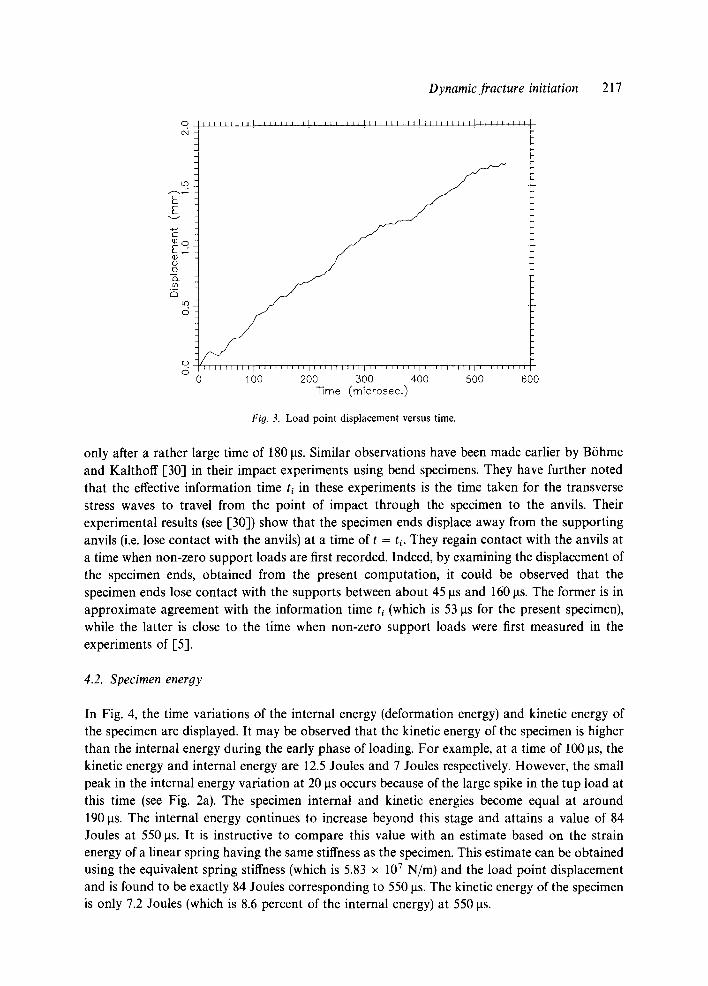
In Fig. 4, the time variations of the internal energy (deformation energy) and kinetic energy of the specimen are displayed. It may be observed that the kinetic energy of the specimen is higher than the internal energy during the early phase of loading. For example, at a time of 100 ~ts, the kinetic energy and internal energy are 12.5 Joules and 7 Joules respectively. However, the small peak in the internal energy variation at 20 p.s occurs because of the large spike in the tup load at this time (see Fig. 2a). The specimen internal and kinetic energies become equal at around 190 laS. The internal energy continues to increase beyond this stage and attains a value of 84 Joules at 550 las. It is instructive to compare this value with an estimate based on the strain energy of a linear spring having the same stiffness as the specimen. This estimate can be obtained using the equivalent spring stiffness (which is 5.83 × 10 7 N/m) and the load point displacement and is found to be exactly 84 Joules corresponding to 550 rts. The kinetic energy of the specimen is only 7.2 Joules (which is 8.6 percent of the internal energy) at 550 ~ts.
3
ktd
f, E~
o
O O
i i i i i i n n l l n l LI I l l J ~ l n J l I l i a I I l l + t In n n n l l l l l l l l l l l l l l l l l l +
Internal Energy
i i
1 O0 200 300 400 500 600 Time (microsec. )
Fio. 4. Specimen energy (in Joules) versus time.
4.3. Dynamic J-integral
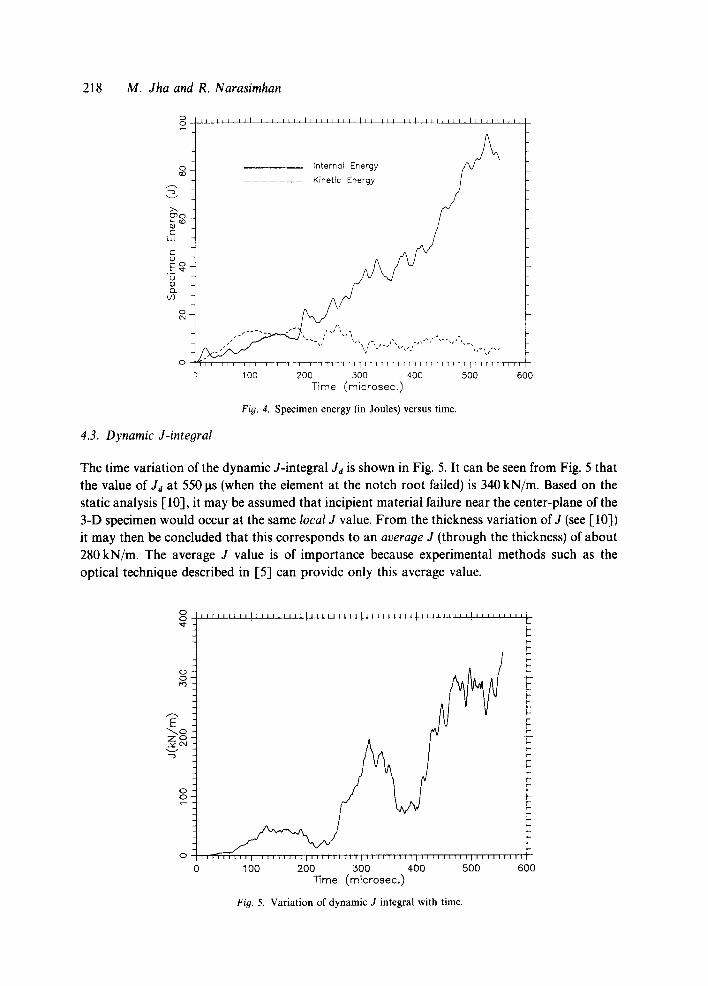
The time variation of the dynamic J-integral Jd is shown in Fig. 5. It can be seen from Fig. 5 that the value of Jn at 550 lxs (when the element at the notch root failed) is 340 kN/m. Based on the static analysis [10], it may be assumed that incipient material failure near the center-plane of the 3-D specimen would occur at the same local J value. From the thickness variation of J (see [10]) it may then be concluded that this corresponds to an average J (through the thickness) of about 280 kN/m. The average J value is of importance because experimental methods such as the optical technique described in I-5] can provide only this average value.
O O ' tO
A
E
O O '
O i i [ i n i l l u u l L U U [ l l l l u l l [ l u [ n l l l [ l u i u n l l l n u l n l l l i l l u I i n l l n T n
100 200 300 400 500 600 ~ m e (microsec. )
Fig. 5. Variation of dynamic J integral with time.
I l r L l l l L I ] l l l l i l l l l l l l n l l l n l l r l l l l l l l l l l l i i i i i t l l l l n l n n l l
218 M. dha and R. Narasimhan
Dynamic fracture initiation 219
The above results compare reasonably well with the experimental observations of Zehnder et al. [5]. They noted that tunneling in the interior of the specimen occurred between 400 to 500 Its and at Jd ~ 240 kN/m in their 5 m/s impact tests. To put these estimates in perspective, it must be mentioned that the average J value at incipient material failure in the 3-D static analysis carried out in [10] was 210 kN/m. The time variation of Jd shown in Fig. 5 is similar to the experimental record given in [5] and displays all its qualitative features.
An average value of J, can be obtained from Fig. 5 as Jdf/tf, where Jdf and t I are the values of Jd and time at incipient failure. This estimate is found to be 6 x l05 kN/m s. However, it can be noticed from Fig. 5 that between 240 to 310its and between 380 to 470Its, J increases very rapidly. The value of J in these time intervals is about 2.4 x l 0 6 kN/m s, which is four times the average value calculated above. It will be seen in Sections 4.5 and 4.6 that this sharp increase in Jd allows for a J-controlled field to stabilize near the notch tip. It also results in rapid evolution of micro-mechanical quantities at the notch root (see Section 4.7).
However, the reason for the rapid increase in Jd during the time intervals noted above should be understood first. To this end, it is necessary to examine the support load shown in Fig. 2b. As noted by B6hme and Kalthoff [30], when the specimen ends regain contact with the anvils (resulting in non-zero support forces), a second impact event takes place. The effect of this impact due to the anvils is experienced by the load point and the notch tip after a delay period of ti (which is about 53 Its in this case). It is expected to accelerate the specimen with respect to the striking tup, and to increase the intensity of the deformation fields near the notch tip, since the bending of the specimen is suddenly enlarged (see discussion in [30]).
The above observation provides an explanation for the behaviour of 'Jd with time which was noted earlier. The first recording of non-zero support forces at 180 Its (Fig. 2b) triggers the rapid increase in J~ after 240 Its (Fig. 5). Figure 2b indicates that the support forces decrease to zero after 260 Its. This results in a sharp reduction in Jd beyond 310 Its. The recording of non-zero support forces again after about 320 Its, gives rise to the rapid increase in Jd beyond 380 Its. In the experimental results given by B6hme and Kalthoff [30], it can be seen that the time variation of the dynamic stress intensity factor K d displays trends which are very similar to those noted above. In numerical simulations of impact tests (see [16, 17]), a zero displacement boundary condition at the supports and a constant velocity condition at the impact point are usually assumed. The foregoing discussion demonstrates that these assumptions do not realistically represent the complicated behaviour arising out of loss of contact between the specimen and the anvil or between the specimen and the striking tup.
4.4. Strain rate at the notch root
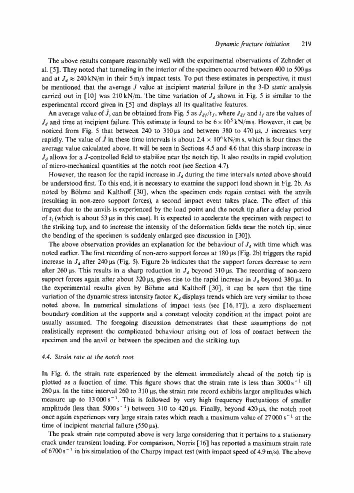
In Fig. 6, the strain rate experienced by the element immediately ahead of the notch tip is plotted as a function of time. This figure shows that the strain rate is less than 3000 s-1 till 260 Its. In the time interval 260 to 310 Its, the strain rate record exhibits larger amplitudes which measure up to 13 000 s-1. This is followed by very high frequency fluctuations of smaller amplitude (less than 5000s -I) between 310 to 420 ~ts. Finally, beyond 420 Its, the notch root once again experiences very large strain rates which reach a maximum value of 27 000 s- 1 at the time of incipient material failure (550 Its).
The peak strain rate computed above is very large considering that it pertains to a stationary crack under transient loading. For comparison, Norris [16] has reported a maximum strain rate of 6700 s- 1 in his simulation of the Charpy impact test (with impact speed of 4.9 m/s). The above
220 M. Jha and R. Narasimhan
o
o 0 0
. L 0
o o
o
o o o
1
I ~ I I I L l I I I , t I I I I I I I I t I I I ~ I I I I i I I I I I ! I I j t I I I i I ~ I I I I ~ I . . . . i J 'I .!
t f T q ' - T I T r r I T I I I T F T ~ 1 I I I I F [ I I r I T I I T I I I I I I I I ] I I [ I I f ; I I l I
0 100 200 300 400 500 600 TTme (micr0sec.)
Fig, 6. Strain rate experienced at the notch root (s l) as function of time.
result implies that strain rate sensitivity should be taken into consideration. However, strain rate experiments on a similar heat treatment of 4340 steel [22] show that the elevation in flow stress with loading rate for this material is relatively low. Thus, while rate sensitivity may not affect the dynamic fracture toughness of this material, it will certainly be an important factor for highly rate sensitive materials.
4.5. N o t c h t ip opening d i sp lacement
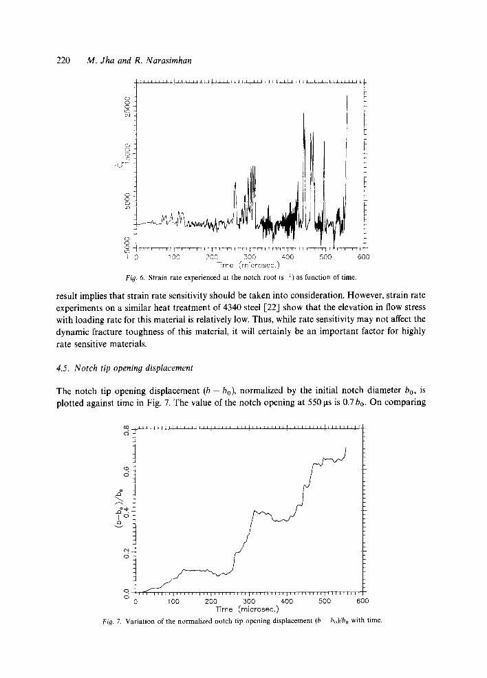
The notch tip opening displacement (b - bo), normalized by the initial notch diameter bo, is plotted against time in Fig. 7. The value of the notch opening at 550 ~ts is 0.7 bo. On comparing
C O J l ] l l i l l J I i ~ l L I I l l ] i ] I I I I I ] I [ i J I I I J [ l l J ~ ] ] I I J I I ~ J I J I I J t ~
0
d
f ~
I o
o
0 i i i 0
0 1 O0 200 .300 4-00 500 600 Time (microsec.)
Fig. 7. Variation of the normalized notch tip opening displacement (b - bo)/b o with time.
Dynamic fracture initiation 221
V
A
io . .
0
0
0
I i I I I l [ l l l l l l l l l [ l l l l l l l l l l l l l l l l l l l ] l l l l l l l l l l l l l l l l l
I [ l l l l l l l l l l l l l l [ [ ] ; ~ q [ l l L l [ l l l r l I l l I ~ l l l l l l ] ; l l l l J l
100 200 300 400 500 600 Time (microsec.)
Fig. 8. Notch tip opening displacement normalized by J/ao versus time.
Figs. 7 and 5, it may be seen that the notch opening exhibits a time variation which is very similar to Ja. In particular, it should be observed that in the time intervals 260 to 310 ~ts and 420 to 475 gs, the notch tip opening displacement increases almost in phase with the dynamic J-integral.
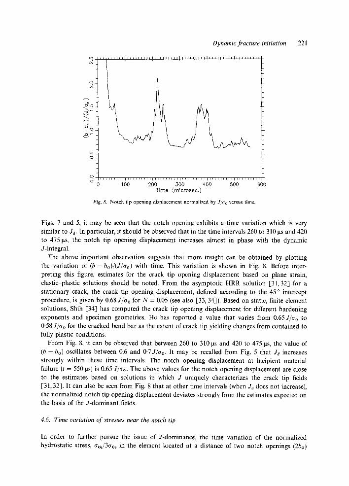
The above important observation suggests that more insight can be obtained by plotting the variation of ( b - bo)/(J/go) with time. This variation is shown in Fig. 8. Before inter- preting this figure, estimates for the crack tip opening displacement based on plane strain, elastic-plastic solutions should be noted. From the asymptotic HRR solution [31,32] for a stationary crack, the crack tip opening displacement, defined according to the 45 ° intercept procedure, is given by 0.68 J/go for N = 0.05 (see also [33, 34]). Based on static, finite element solutions, Shih [34] has computed the crack tip opening displacement for different hardening exponents and specimen geometries. He has reported a value that varies from 0.65J/go to 0.58 J/go for the cracked bend bar as the extent of crack tip yielding changes from contained to fully plastic conditions.
From Fig. 8, it can be observed that between 260 to 310 las and 420 to 475 gs, the value of ( b - bo) oscillates between 0.6 and 0"7J/go. It may be recalled from Fig. 5 that Ju increases strongly within these time intervals. The notch opening displacement at incipient material failure (t = 550 las) is 0.65 J/go. The above values for the notch opening displacement are close to the estimates based on solutions in which J uniquely characterizes the crack tip fields [3t, 32]. It can also be seen from Fig. 8 that at other time intervals (when Je does not increase), the normalized notch tip opening displacement deviates strongly from the estimates expected on the basis of the J-dominant fields.
4.6. Time variation of stresses near the notch tip
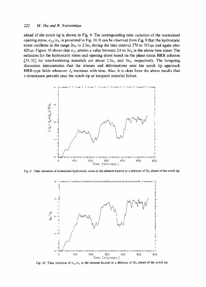
In order to further pursue the issue of J-dominance, the time variation of the normalized hydrostatic stress, akk/3gO, in the element located at a distance of two notch openings (2bo)
222 M. Jha and R. Narasimhan
ahead of the notch tip is shown in Fig. 9. The corresponding time variation of the normalized
opening stress, a22/ao, is presented in Fig. 10. It can be observed from Fig. 9 that the hydrostatic
stress oscillates in the range 2ao to 2.3ao during the time interval 270 to 315 ItS and again after
420 las. Figure 10 shows that a22 attains a value between 2.6 to 3tro in the above time zones. The estimates for the hydrostatic stress and opening stress based on the plane strain HRR solution
1-31, 32] for non-hardening materials are about 2.3ao and 3Cro, respectively. The foregoing
discussion demonstrates that the stresses and deformations near the notch tip approach HRR-type fields whenever Ja increases with time. Also, it is clear from the above results that
J-dominance prevails near the notch tip at incipient material failure.
b O rO
0'3
4-
4- @
v
I I I I I I I d t l l l l l l l l l l l l l l l l J l l l ~ l l l J l l l l l l l l t l l l l l l ] l l l l l l
r l i
100 200 300 400 500 600 Time (microsec.)
Fig. 9. Time variation of normalized hydrostatic stress in the element located at a distance of 2bo ahead of the notch tip.
i l d l l l l t l i J l l l l l l l l l L I I I I l l i i l l g l l l i l i J I l i L I l i t l l J L I I I
r,'3
b o
o i i i
1 O0 200 300 400 500 600 Time (mTcrosec.)
Fig. I0. Time variation of 0 " 2 2 / ( 7 0 in the element located at a distance of 2bo ahead of the notch tip.
Dynamic fracture initiation 223
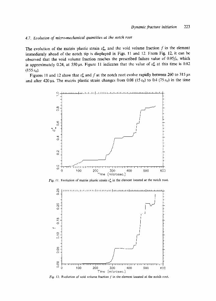
4.7. Evolution of micro-mechanical quantities at the notch root
The evolution of the matrix plastic strain e~, and the void volume fraction f in the element immediately ahead of the notch tip is displayed in Figs. l l and 12. From Fig. 12, it can be observed that the void volume fraction reaches the prescribed failure value of 0.95fF, which is approximately 0.24, at 550 ~ts. Figure 11 indicates that the value of e~ at this time is 0.82
(155 Co). Figures 11 and 12 show that ePm and f at the notch root evolve rapidly between 260 to 315 ~ts
and after 420 rts. The matrix plastic strain changes from 0.08 (15 ~o) to 0.4 (75 Co) in the time
] I I I I I I I I l ~ l l ~ l l l I ~ I I [ J l L I I I J I I I I I I I l l l l l L i i n l l l n n n )1
0
1 l l r l [ 11 [ I I I l l l l l ] l l l l l l l l l l l l l l l l [ l l 11
0 100 200 500 400 500 600 Time (microsec.)
Fig. I1. Evolution of matrix plastic strain ~ in the element located at the notch root.
I I I I I l l J l l ] i f l l ] l l t ] L I I 2 1 1 1 1 I l J l I t l l l ~ l l t l I I I I I I I I Z l
O
o / 0
0
° t o I
o .
0
° r 0 i ] i 1 1 1 1 ] 1 1 1 i i i i ] i i i i i i i i i i i ( [ r ~ - l ~ l r l l l l l l l l i
o 0 100 200 300 400 500 600 TTme (microsee.)
Fig. 12. Evolution of void volume fraction f in the element located at the notch root.
224 M. dha and R. Narasimhan
interval 260 to 315 Its, and from 0.41 to 0.77 between 420 to 470Its. Also, in the above time intervals, the void volume fraction increases from 0 to 0.055 and from 0.055 to 0.17, respectively. It may also be noted that these quantities do not display appreciable variation at other time zones. Thus, it may be concluded on referring to Fig. 5 that the evolution of micro-mechanical quantities and the accumulation of damage at the notch root correlate directly with the time variation of Jd. The results presented in this section together with those of Sections 4.5 and 4.6, provide a firm basis for the use of Jd to characterize fracture initiation under highly transient loading such as that encountered in the present experiments.
4.8. Contour plots
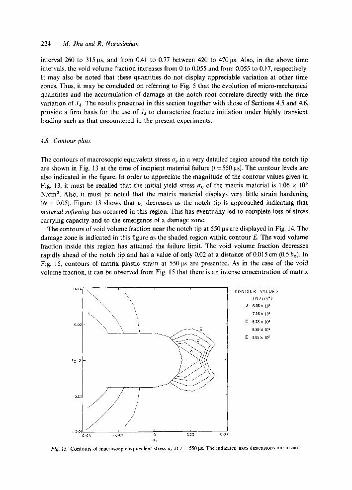
The contours of macroscopic equivalent stress ae in a very detailed region around the notch tip are shown in Fig. 13 at the time of incipient material failure (t = 550 Its). The contour levels are also indicated in the figure. In order to appreciate the magnitude of the contour values given in Fig. 13, it must be recalled that the initial yield stress tro of the matrix material is 1.06 x 10⁵ N/cm 2. Also, it must be noted that the matrix material displays very little strain hardening (N = 0.05). Figure 13 shows that o- e decreases as the notch tip is approached indicating that material softening has occurred in this region. This has eventually led to complete loss of stress carrying capacity and to the emergence of a damage zone.
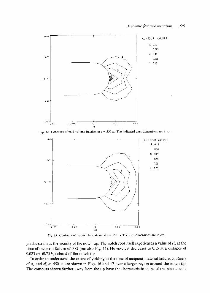
The contours of void volume fraction near the notch tip at 550 Its are displayed in Fig. 14. The damage zone is indicated in this figure as the shaded region within contour E. The void volume fraction inside this region has attained the failure limit. The void volume fraction decreases rapidly ahead of the notch tip and has a value of only 0.02 at a distance of 0.015 cm (0.5 bo). In Fig. 15, contours of matrix plastic strain at 550 tas are presented. As in the case of the void volume fraction, it can be observed from Fig. 15 that there is an intense concentration of matrix
0 .04
0.02
X 2 0
- 0.02
E
- 0.102 I t 0 0.02 - 0.0
-0.04 0,04
CONTOUR VALUES
( N / c m 2 )
A 6.05 x 10 "4
7.16 x 10⁴
C 8.28 x 10⁴
9,39 x 10⁴
E 1,05 x 1~
Fig. 13. Contours of macroscopic equivalent stress ae at t = 550/as. The indicated axes dimensions are in cm.
Dynamic fracture initiation 225
0.04
0.02
X 2 0
-0,02
I f I
C O N T O U R V A L U E S
A 0.02
0.065
C 0.11
0.155
E 0.20
- 0 .04 [ I I - 0 .04 - 0 . 0 2 0 0.02 0.0 L
Xl
Fig. 14. Contours of void volume fraction at t = 5 5 0 Ins. The indicated axes dimensions are in cm.
0,04
0.02
X 2 0
- 0 . 0 2
- o . o 4 - 0 . 0 4
CONTOUR V A L U E S
A 0.15
0.26
C 0.37
0.48
0.59
F 0.70
I - 0.102 0 0102 0.0,~
XI
Fig. 15. Contours of matrix platic strain at t = 5 5 0 tas. The axes dimensions are in cm.
plastic strain at the vicinity of the notch tip. The notch root itself experiences a value of ePm at the time of incipient failure of 0.82 (see also Fig. 11). However, it decreases to 0.15 at a distance of 0.023 cm (0.75 bo) ahead of the notch tip.
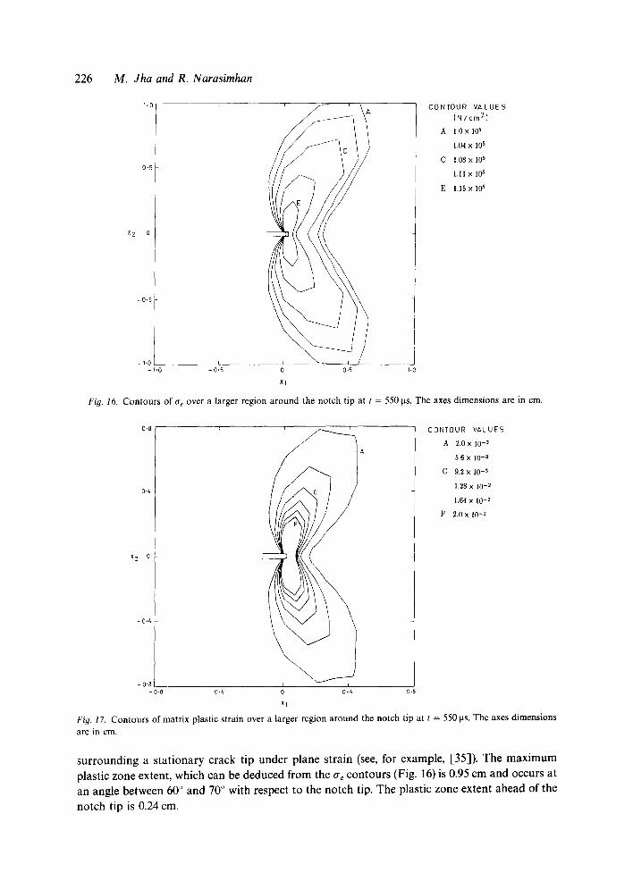
In order to understand the extent of yielding at the time of incipient material failure, contours of Cre and E p at 550 gs are shown in Figs. 16 and 17 over a larger region around the notch tip. The contours shown farther away from the tip have the characteristic shape of the plastic zone
2 2 6 M. Jha and R. Narasimhan
1,0 J
0.5
X 2 0
-0.5
C O N T O U R V A L U E S
( N / c m 2 ]
A 1.0 x 10 s
1.04 x I05
P C 1.08 x 10 ,5
I . I I x I0 ~
E 1.15 x 10 6
- t .O - 0 ,5 0 0.5 I -0
Xl
Fig. 16. C o n t o u r s o f a t o v e r a l a rge r r e g i o n around the notch tip at t = 550 Its. T h e axes d i m e n s i o n s are in cm.
0.8 ~ CONTOUR V A L U E S
A 2.0 x 10 .3 A
5.6 x 10 -3
C 9.2 x 10 -~
1.28 x 10 -2 0.4
1,64 X 10 -2
F 2.0 x 10-~
x 2 0
- 0+4
-0.8 - o . 7 -o%, ' J 0 0 z, 0.8
Xl
Fig. 17. C o n t o u r s o f m a t r i x p l a s t i c s t r a in ove r a l a rge r r e g i o n around the notch tip at t = 550 ps. The axes dimensions
are in cm.
surrounding a stationary crack tip under plane strain (see, for example, [35]). The m a x i m u m plastic zone extent, which can be deduced from the ae contours (Fig. 16) is 0.95 cm and occurs at an angle between 60 ° and 70 + with respect to the notch tip. The plastic zone extent ahead of the
notch tip is 0.24 cm.
Dynamic fracture initiation 227
The above plastic zone dimensions can be compared with the small-scale yielding results given by Rice and Tracey [35] based on a static, finite element analysis for a perfectly plastic material. Rice and Tracey have reported that the maximum plastic zone extent is given by 0.15 (K/0.o) 2 and that it is attained at an angle of 70 ° with the crack tip. Also, the plastic zone extent in front is given in [35] as 0.04(K/0.o) 2. On using the stress intensity factor, K = x / E J~(1 - v2), corresponding to J = 340 kN/m, the maximum plastic zone size and the plastic zone extent in front are found to be 1 cm and 0.27 cm, respectively. These are very close to the results obtained by the present computations.
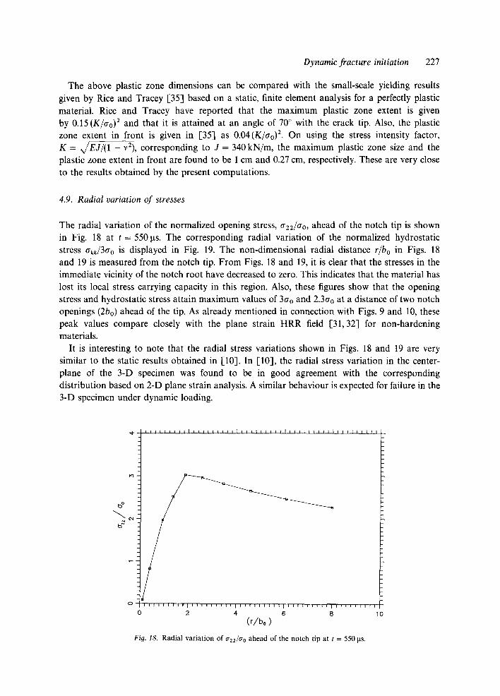
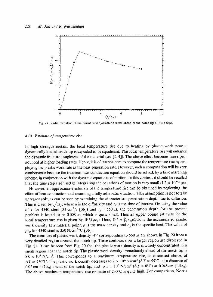
4.9. Radial variation of stresses
The radial variation of the normalized opening stress, 0"22/0"0, ahead of the notch tip is shown in Fig. 18 at t = 550 ~ts. The corresponding radial variation of the normalized hydrostatic stress 0"kk/30"0 is displayed in Fig. 19. The non-dimensional radial distance r/bo in Figs. 18 and 19 is measured from the notch tip. From Figs. 18 and 19, it is clear that the stresses in the immediate vicinity of the notch root have decreased to zero. This indicates that the material has lost its local stress carrying capacity in this region. Also, these figures show that the opening stress and hydrostatic stress attain maximum values of 3go and 2.30.0 at a distance of two notch openings (2bo) ahead of the tip. As already mentioned in connection with Figs. 9 and 10, these peak values compare closely with the plane strain HRR field [31,32] for non-hardening materials.
It is interesting to note that the radial stress variations shown in Figs. 18 and 19 are very similar to the static results obtained in [10]. In [10], the radial stress variation in the center- plane of the 3-D specimen was found to be in good agreement with the corresponding distribution based on 2-D plane strain analysis. A similar behaviour is expected for failure in the 3-D specimen under dynamic loading.
"4"
0
I I I I l l l l l l l l l l l l t l l l i l l l l l i l i l l l l l l l r l l i l l l l l l l f l
I ] I I I I [ 1 1 I I I I I I I l l I I I I l l J i l l [ i i i i f i i i i ~ i i i l l i i i I
0 2 4 6 8 10 (r/bo)
Fig. 18. Radial variation of 0"22/0" 0 ahead of the notch tip at t = 550 ~ts.
228 M. Jha and R. Narasimhan
I I I I J I I I I I I I I I I I I 1 [ I I I I I I I I I ~ I I I I I [ I I I I ] [ 1
b o
b = +~ b ~ +_
o i i i l [ l l l l l l l | l l i i l l l l l l [ l l i i [ l l l l l l l i [ l l I [ i I i
0 2 4 6 8 0
(r/bo) Fig. 19. Radial variation of the normalized hydrostatic stress ahead of the notch tip at t = 550 las.
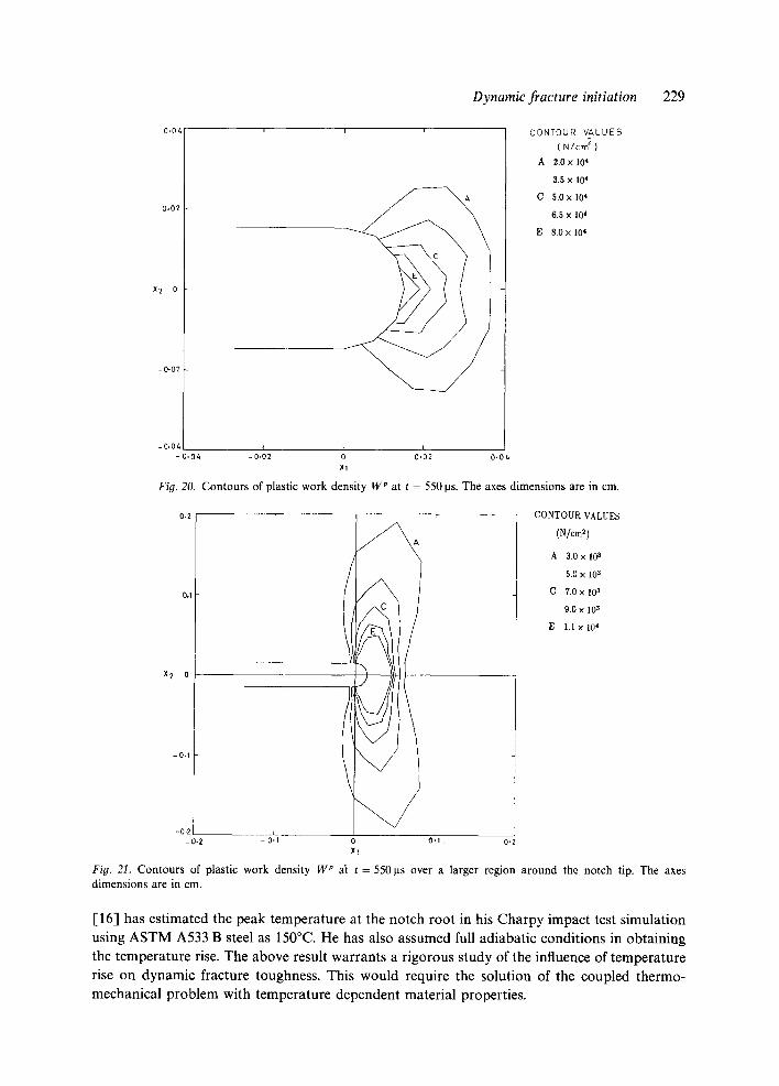
4.10. Estimate of temperature rise
In high strength metals, the local temperature rise due to heating by plastic work near a dynamically loaded crack tip is expected to be significant. This local temperature rise will enhance the dynamic fracture toughness of the material (see [2, 4]). The above effect becomes more pro- nounced at higher loading rates. Hence, it is of interest here to compute the temperature rise by em- ploying the plastic work rate as the heat generation rate. However, such a computation will be very cumbersome because the transient heat conduction equation should be solved, by a time marching scheme, in conjunction with the dynamic equations of motion. In this context, it should be recalled that the time step size used in integrating the equations of motion is very small (1.2 x 10 -2 ~ts).
However, an approximate estimate of the temperature rise can be obtained by neglecting the effect of heat conduction and assuming a fully adiabatic situation. This assumption is not totally unreasonable, as can be seen by examining the characteristic penetration depth due to diffusion. This is given by , , ~ I , where ~ is the diffusivity and t I is the time of interest. On using the value of ~ for 4340 steel (0.1 cm2/s [36]) and t I = 550~ts, the penetration depth for the present problem is found to be 0.008 cm which is quite small. Thus an upper bound estimate for the
t , p local temperature rise is given by WP/(pcp). Here, W p = ~o aueu dr, is the accumulated plastic work density at a material point, p is the mass density and cp is the specific heat. The value of
pCp for 4340 steel is 350 N/cm2°C [36]. The contours of plastic work density W p corresponding to 550 las are shown in Fig. 20 from a
very detailed region around the notch tip. These contours over a larger region are displayed in Fig. 21. It can be seen from Fig. 20 that the plastic work density is intensely concentrated in a small region near the notch tip. The plastic work density immediately ahead of the notch tip is 8.0 × 10*N/cm 2. This corresponds to a maximum temperature rise, as discussed above, of AT ~ 230°C. The plastic work density decreases to 2 x 10⁴ N/cm 2 (AT ~ 55°C) at a distance of 0.02 cm (0.7 bo) ahead of the notch tip, and to 3 × 1 0 3 N/cm 2 (AT ~ 8°C) at 0.045 cm (1.5 bo). The above maximum temperature rise estimate of 230°C is quite high. For comparison, Norris
0.06
0.02
X 2 0
-0 .02
X2 0
Dynamic fracture initiation 229
C O N T O U R V A L U E S
( N / c m 2 )
A 2.0 x 10⁴
3.5 x 10⁴
C ,5.0 x 10 'j
6.5 x 10⁴
E 8.0 x 10⁴
-O,I
X1
-0-2 -0.2 - o'.1 o o'.1 o.~
Fig. 21. Contours of plastic work density W p a~ t = 550ps over a larger region around the notch tip. The axes dimensions are in cm.
[16] has estimated the peak temperature at the notch root in his Charpy impact test simulation using A S T M A533 B steel as 150°C. He has also assumed full adiabatic conditions in obtaining the temperature rise. The above result warrants a rigorous study of the influence of temperature rise on dynamic fracture toughness. This would require the solution of the coupled thermo- mechanical problem with temperature dependent material properties.
-0.04 r i I - 0 .04 -0.02 0 0.02 0.06
XI
Fig. 20. C o n t o u r s of plastic w o r k density W p at t = 5 5 0 [is. The axes d imens ions are in cm.
o.2 C O N T O U R VALUES
(N/¢~)
A 3.0 x I0 3
5.0 x 10³
0.1 C 7.0 x 10³
g.O X 10 3
E I .I x 10 4
230 M. Jha and R. Narasimhan
5. Conclusions
The main conclusions of this investigation are summarized below:
1. An impact experiment, performed in [5] using a three-point bend specimen of 4340 steel has been analyzed by a plane strain, transient finite element procedure. The calculations indicate that incipient material failure at the notch tip occurs at about 550 Ixs. The value of Jd at this time is 340 kN/m. It is predicted that local failure near the center-plane of the specimen in a 3-D analysis would occur at an average Jd (through the thickness) of 280 kN/m. These results are in reasonable agreement with experiments [5].
2. The recording of non-zero support loads at 180 Ixs and 320 I~s triggers rapid increase in Ja (with J ~ 2.4 x 10 6 kN/m s) after 240 and 380 Ixs. The delay period conforms closely to the propagation time of the transverse stress waves from the support point through the specimen to the load point.
3. The J-controlled deformation fields given in [31-34] are established near the notch tip between 260 ~ts and 310 las and again after 420 ~ts. These intervals fall within the range where Jd increases rapidly with time.
4. The evolution of micro-mechanical quantities like e~ and f, and the accumulation of damage at the notch root correlate closely with time variation of Ja. There is no evolution of these quantities at time intervals where Ja does not exhibit an increase.
5. The maximum strain rate experienced at the notch root is found to be 27 000 s- 1. This large value implies that strain rate effects on dynamic fracture toughness should be considered for materials which exhibit appreciable amounts of rate sensitivity.
6. An upper bound estimate for the notch root temperature rise is found to be 230°C. This decreases to 8°C at a distance of 1.5 notch openings (1.5 bo) ahead of the notch tip.
Acknowledgements
Th authors would like to express their gratitude to Professor A.J. Rosakis of California Institute of Technology, Pasadena, for sending an advance copy of [5] and for a helpful discussion on this work. The second author also wishes to gratefully acknowledge the Department of Science and Technology (Government of India) for financial support through sponsored Project No. Ill-5 (48)/89-ET.
References
1. D.A. Shockey (ed.), in Metals Handbook, American Society of Metals, 9th edn., Vol. 8 (1983) 259-297. 2. A.H. Priest, in Proceedings of International Conference on Dynamic Fracture Toughness, Welding Institute,
Cambridge, Paper 10 (1976) 95-111. 3. L.S. Costin and J. Duffy, Transactions ASME Series H Journal of Engineering Materials and Technology 101 (1979)
258-263. 4. J.R. Rice and N. Levy, in Physics of Strength and Plasticity, A. Argon (ed.), MIT Press (1969). 5. A.T. Zehnder, A.J. Rosakis and S. Krishnaswamy, International Journal of Fracture 42 (1990) 209-230. 6. A.T. Zehnder and A.J. Rosakis, Journal of Applied Mechanics 57 (1990) 618-626. 7. A.L. Gurson, Transactions ASME Series H Journal of Engineering Materials and Technology 99 (1977) 2-15. 8. J. Pan, M. Saje and A. Needleman, International Journal of Fracture 21 (1983) 261-278.
Dynamic f rac ture initiation 231
9. V. Tvergaard and A. Needleman, Acta Metalluroica 32 (1984) 157-169. 10. R. Narasimhan, A.J. Rosakis and B. Moran, International Journal of Fracture, to be published. 11. T. Nakamura, C.F. Shih and L.B. Freund, International Journal of Fracture 27 (1985) 229-243. 12. V. Tvergaard, in Advances in Applied Mechanics 27 (1990) 83-151. 13. S. Aoki, K. Kishimoto, A. Takeya and M. Sakata, International Journal of Fracture 24 (1984) 267-278. 14. N. Aravas and R.M. McMeeking, International Journal of Fracture 29 (1985) 21-38. 15. R. Becker, A. Needleman, S. Suresh, V. Tvergaard and A.K. Vasudevan, Acta Metallurgica 37 (1989) 99-120. 16. D.M. Norris, Engineerin O Fracture Mechanics 11 (1979) 261-274. 17. V. Tvergaard and A. Needleman, International Journal of Fracture 37 (1988) 197-215. 18. V. Tvergaard, International Journal of Fracture 17 (1981) 389-407. 19. T.B. Cox and J.R. Low, Metallurgical Transactions 5 (1974) 1457-1470. 20. L.M. Brown and J.D. Embury, in Microstructure and Design of Alloys, Proceedings of the Third International
Conference on the Strenoth of Metals and Alloys, Cambridge, England (1973) 164-179. 21. H. Anderson, Journal of Mechanics and Physics of Solids 25 (1977) 217-233. 22. S. Tanimura and J. Duffy, International Journal of Plasticity 2 (1986) 21-35. 23. C.C. Chu and A. Needleman, Transactions ASME Series H Journal of Enoineerin 0 Materials and Technology 102
(1980) 249-256. 24. K.J. Bathe, Finite Element Procedures in Engineerin 9 Analysis, Prentice Hall, Englewood Cliffs, New Jersey (1982). 25. T.J.R. Hughes, in Computational Methods for Transient Analysis, T. Belytshko and T.J.R. Hughes (eds.), Elsevier,
Amsterdam (1983) 67-155. 26. T. Belytshko, in Computational Methods for Transient Analysis, Elsevier, Amsterdam (1983) 1-65. 27. D. Pierce, C.F. Shih and A. Needleman, Computers and Structures 18 (1984) 875-887. 28. V. Tvergaard, Journal of Mechanics and Physics of Solids 30 (1982) 399-425. 29. T. Nakamura, C.F. Shih and L.B. Freund, Engineerin 9 Fracture Mechanics 25 (1986) 323-339. 30. W. B6hme and J.F. Kalthoff, International Journal of Fracture 20 (1982) R139-R143. 31. J.W. Hutchinson, Journal of Mechanics and Physics of Solids 16(1968) 337-347. 32. J.R. Rice and G.F. Rosengren, Journal of Mechanics and Physics of Solids 16 (1968) 1-12. 33. C.F. Shih, Tables of HRR Singular Field Quantities, Brown University Report (1983). 34. C.F. Shih, Journal of Mechanics and Physics of Solids 29 (1981) 305-326. 35. J.R. Rice and D.M. Tracey, in Numerical Methods in Structural Mechanics, S.J. Fenves et al. (eds.), Academic Press,
New York (1973) 585-623. 36. Aerospace Structural Metals Handbook, Metals and Ceramics Information Center, Battelle Columbus Laboratories,
Columbus, Ohio (1989).
Related Documents