A FIELD INVESTIGATION OF COMPOSITE MUD BRICK COMPRESSIVE STRENGTH By Kevin D. Hale A THESIS Submitted in partial fulfillment of the requirements for the degree of MASTER OF SCIENCE In Mechanical Engineering MICHIGAN TECHNOLOGICAL UNIVERSITY 2015 © 2015 Kevin D. Hale

Welcome message from author
This document is posted to help you gain knowledge. Please leave a comment to let me know what you think about it! Share it to your friends and learn new things together.
Transcript

A FIELD INVESTIGATION OF COMPOSITE
MUD BRICK COMPRESSIVE STRENGTH
By
Kevin D. Hale
A THESIS
Submitted in partial fulfillment of the requirements for the degree of
MASTER OF SCIENCE
In Mechanical Engineering
MICHIGAN TECHNOLOGICAL UNIVERSITY
2015
© 2015 Kevin D. Hale

This thesis has been approved in partial fulfillment of the requirements for the
Degree of MASTER OF SCIENCE in Mechanical Engineering.
Department of Mechanical Engineering – Engineering Mechanics
Thesis Co-Advisor: Dr. Michelle H. Miller
Thesis Co-Advisor: Dr. Ibrahim Miskioglu
Committee Member: Dr. Kari B. Henquinet
Department Chair: Dr. William W. Prebedon

Contents
List of Figures ...................................................................................................................viii
List of Tables ....................................................................................................................... x
Acknowledgements ........................................................................................................... xi
Abstract ...............................................................................................................................xii
Chapter 1 .............................................................................................................................. 1
Introduction ........................................................................................................................ 1
1.1 Background ................................................................................................................ 1
1.2 History of Earth Construction ................................................................................ 2
1.3 Composite Mud Bricks............................................................................................. 4
1.31 Fibers .................................................................................................................... 4
1.32 Matrix Stabilizers ............................................................................................... 6
1.33 Chemical Coatings .............................................................................................. 6
1.4 Field Tests.................................................................................................................. 7
1.41 Tests for soil content .......................................................................................... 7
1.42 Weathering tests ................................................................................................. 9
1.43 Strength tests .................................................................................................... 10
1.5 Current State of Earth Construction .................................................................... 12
Chapter 2 ........................................................................................................................... 15
Materials & Methods ........................................................................................................ 15
v
2.1 Traditional Brick Production ................................................................................ 15
2.2 Experimental Materials ........................................................................................ 16
2.11 Soil ...................................................................................................................... 16
2.12 Fibers ................................................................................................................. 16
2.2 Specimen Production ............................................................................................ 17
2.22 Composite Bricks ............................................................................................. 19
2.23 Experimental Setup ......................................................................................... 22
2.3 Experimental Methods .......................................................................................... 27
2.31 Brick measurements ........................................................................................ 27
2.32 Applying load P ................................................................................................ 28
2.33 Calculating P ..................................................................................................... 28
Chapter 3 ........................................................................................................................... 30
Results & Conclusion ....................................................................................................... 30
3.1 Results ...................................................................................................................... 30
3.11 Brick Production Quality ................................................................................. 30
3.12 Compressive Strength ...................................................................................... 32
3.13 Feasibility of 3-point Bending Test ................................................................ 44
3.2 Conclusion .............................................................................................................. 45
Appendix A ........................................................................................................................ 47
Experimental Details for Calculating Maximum Dry Density (MDD) at Optimum
Moisture Content (OMC) ............................................................................................ 47
Drop Ball Test and Soil Workability ...................................................................... 49
Evaluation of Field Tests ............................................................................................. 51
Sedimentation in a bottle ........................................................................................ 51
Cigar test .................................................................................................................... 52
vi

Wire brush test.......................................................................................................... 53
Drip test ..................................................................................................................... 54
References ......................................................................................................................... 56
vii
List of Figures
Figure 1: 3-point bending test......................................................................................... 10
Figure 2: Arch behavior of a brick under 3-point bending compression ................. 11
Figure 3: Free body diagram of fictitious support beams used to model arch
behavior ............................................................................................................................. 11
Figure 4: Termite hill soil with initial digging on left hand side ............................... 16
Figure 5: Three pronged fork made from bamboo and used to clean straw of blades
and sheathes ...................................................................................................................... 17
Figure 6: Cutting straw fibers ......................................................................................... 17
Figure 7: Soil sieve made from chicken wire and tree branches ................................ 19
Figure 8: Mixing of the soil, water and straw fibers .................................................... 19
Figure 9: Wooden mold used to form the mud bricks ................................................ 21
Figure 10: The classification of brick quality ................................................................ 22
Figure 11: First iteration of the 3-point bending test .................................................. 23
Figure 12: Basic schematic of the lever system ............................................................ 24
Figure 13: Cattle plow used to create the lever ............................................................. 24
Figure 14: 19th century foot-powered band saw used as fulcrum and testing
support platform .............................................................................................................. 25
Figure 15: First iteration of 3-point bending lever system ......................................... 25
Figure 16: 3-point bending apparatus with extended lever ........................................ 26
Figure 17: Final iteration of 3-point bending test apparatus ..................................... 27
Figure 18: Free body diagram of the lever with four buckets attached..................... 29
Figure 19: Compressive strength of no-crack bricks ................................................... 34
Figure 20: Average compressive strength of no-crack bricks for each testing
sample ................................................................................................................................ 35
Figure 21: Compressive strength of no-crack and small crack bricks ....................... 37
viii
Figure 22: Average compressive strength of no-crack and small crack bricks for
each testing sample .......................................................................................................... 38
Figure 23: Compressive strength of all bricks tested .................................................. 40
Figure 24: Average compressive strength for all bricks in each testing sample ...... 41
Figure 25: Container used to make MDD volume samples ........................................ 47
Figure 26: Soil samples molded at various moisture content .................................... 48
Figure 27: Graph displaying optimum moisture content ........................................... 49
Figure 28: Drop ball test at 14% moisture content ...................................................... 50
Figure 29: Drop ball test at 16% moisture content ...................................................... 50
Figure 30: Drop ball test at an OMC of 20% ................................................................ 50
Figure 31: Drop ball test at 24% moisture content ...................................................... 51
Figure 32: Wire brush with 3kg of weight attached..................................................... 53
Figure 33: Mud brick after receiving the wire brush test............................................ 54
Figure 34: Experimental setup of drip test ................................................................... 55
ix

List of Tables
Table 1: Brick production quality statistics for each type of composite produced .. 31
Table 2: Compressive strength of each composite calculated using no-crack bricks
only ..................................................................................................................................... 33
Table 3: Compressive strength of each composite calculated using no-crack and
small crack bricks ............................................................................................................. 36
Table 4: Compressive strength of each composite calculated using all tested bricks
............................................................................................................................................. 39
Table 5: Average mass and corresponding moisture content of samples for MDD
and OMC testing ............................................................................................................... 48
Table 6: Results from cigar test ...................................................................................... 53
Table 7: Drip test pit depth ratings ................................................................................ 55
x
Acknowledgements I would like to thank Dr. Michelle H. Miller and Dr. Ibrahim Miskioglu for their
unwavering support and willingness to help me succeed. Their insightful and
prompt guidance was essential throughout the entire process. I would also like to
thank my students and friends Elias Lourenco Carina, Assane Amade Cabado,
Ernesto Filimone Mahache and Acacio Mansur Heidar whose tireless efforts,
dedication and knowledge were indispensable to the realization of this project. My
thanks and appreciation go out to my committee member and Peace Corps
Master’s International program director Dr. Kari B. Henquinet who on short
notice graciously provided essential feedback for improving this thesis. Last but
not least I would like to thank all my friends and family who support me in
everything I attempt throughout life may they become successes or failures.
xi
Abstract
It has been highlighted in numerous publications that in the field of earth
construction there is a strong disconnect between experimental work in the
laboratory and its application in the field. The current study attempts to help
bridge this gap with a field test conducted in Nampula, Mozambique. Mud bricks
were made with a simple hand mold and reinforced with bamboo and straw fibers.
Fibers were cut into lengths of 3 cm and 6 cm while being mixed in fractions of
0.125%, 0.25% and 0.50% by weight and compressive strength was measured
using an application of the 3-point bending test. It was found that neither straw
nor bamboo increased the composite brick’s strength and in fact a decrease of
strength was recorded. An increase in brick strain energy density was observed
with increasing fiber fraction.
xii
Chapter 1
Introduction
1.1 Background
The current study was conducted as part of the Peace Corps Master’s International
program in which the author served two years as a Peace Corps volunteer in
Nampula, Mozambique while simultaneously conducting field research in partial
fulfillment of a Master’s of Science in Mechanical Engineering with Michigan
Technological University. During this time the author lived in a mud brick
community of approximately 2,000 people and it was observed that many homes
had collapsed over the years due to brick deterioration caused by weathering.
Climatically Mozambique has a tropical wet and dry climate characterized by six
months of dry season and six months of rainy season. The average rainfall in
Nampula is approximately 1008.5 mm/year [1]. The use of mud bricks in areas of
heavy rainfall can cause homes to degrade and ruin prematurely. This forces
homeowners’ to continuously focus on housing repairs and ultimately the entire
reconstruction of a home. It was observed that many homeowners’ began
reconstruction after roughly seven to eight years and needed one to two years for
completion depending on outside circumstances such as weather and other
personal factors.
The constant attention required for maintaining the stability of mud brick housing
consumes pertinent time that could be utilized to develop other aspects of one’s
life such as food security and income development which all relate to health, life
expectancy and emerging out of poverty. With this in mind it was decided to
1

investigate the current field of earth construction and methods therein for
improving the strength properties of mud bricks.
1.2 History of Earth Construction
The use of earth as a building material reaches far back in humanity. One of the
earliest known examples are the Zhoukoudian caves. Discovered in the 1920’s
southwest of modern Beijing and dating back anywhere from 600,000-780,000
years ago, they represent one of the earliest known instances of earth being used
for home construction [2]. The first evidence of earth being formed into a brick
was discovered in the upper Tigris basin and dates back as far as 7500 BC [3].
Since then, earth bricks have been used extensively throughout history to help
create masterful structures such as the Great Wall of China, temples for Ramses II
in Egypt, the Ishtar Gate in Babylon and countless pyramids in Mesoamerica [2].
Requiring only soil and water, mud bricks are one of the simplest building
materials. Historically it was learned through trial and error that a soil must
contain clay in order to form a cohesive brick. It is now recommended in the
literature that soils contain a clay content of anywhere from 10-22% depending on
the researcher proposing the mixture [4]. Composite mud bricks are soil-water
mixtures that are combined with an additive such that a given property of the
composite brick will improve. Animal hair, animal manure and various plant fibers
are historically common additives.
As civilizations developed so did the materials and engineering involved with
construction. Countries with access to such development abandoned earth
construction as an archaic method while countries without access continued to
depend upon earth construction as the only means to housing. This change of
direction in developed countries caused the focus of academic research to follow
suit. Therefore the remaining half of the world living void of access to advanced
materials continued to rely on earth construction as the principal means of
housing while it persisted in its rudimentary undeveloped form.
2

Only in recent decades has earth construction received a renewed attention by the
academic community [5]. This is due to the common knowledge that populations
are growing, resources are finite and relying on energy intensive materials such as
steel and concrete is not practical. Environmentally sustainable solutions must be
researched. In response, countries such as France, New Zealand, Australia,
Germany, Spain, Peru, Zimbabwe and the state of New Mexico have all put forth
national documents regarding the use of natural earth as a construction material.
There have also been recommendations put forth for the continent of Africa by
CRATerre [4], [6].
Unfortunately, the new found interest in earth construction is highly focused
toward its application in developed countries. The large majority of people
currently struggling with the inherent difficulties of living in hand-constructed
earth built homes are essentially neglected. This is demonstrated by the quantity of
laboratory based research that does not carry any direct application in the field at a
community based level. Experiments which are executed using sophisticated
laboratory equipment that operate at high precision under fastidiously controlled
conditions are not transferable to the field in which conditions are highly dynamic
and processes are performed using simple hand tools. Therefore field testing
methods must be developed that facilitate the advancement of earth construction
in underdeveloped countries.
To support this cause many authors have contributed greatly by publishing
detailed works that list methods for field testing and recommended values one
should obtain [7]-[9]. There have also been strides in developing computer aided
predictive models for determining mechanical properties of composite bricks [8],
[9]. However, often times these field tests only determine basic soil properties and
recommended methods and results are vague or contradict each other [4]. There
are very few field tests meant to quantify the overall strength and durability of a
mud brick which is imperative to the process of developing an improved version.
One field test that has been recommended for determining compressive strength is
the 3-point bending test, yet there still does not exist any literature detailing its use
in the field leaving its feasibility unknown [10]. Similar arguments can be made
3
with regard to the true effects of reinforcing fibers when composite bricks are
produced under field conditions. Therefore the purpose of the current research is
to provide such a study and lead the way for future experiments to advance the
work.
1.3 Composite Mud Bricks
A composite mud brick is a soil-water mixture (the matrix) combined with an
additive such that the new composite material has improved mechanical or
chemical properties. For clarity the matrix additives will be divided into three
categories: fibers, matrix stabilizers and chemical coatings.
1.31 Fibers
Fibers are typically produced in short (1-5 cm) prismatic shapes from materials of
high tensile strength that can be thought of as ideally inextensible. They are cut to
predetermined lengths and mixed with the matrix at specified proportions based
on weight or volume. Mixing fibers by weight is more common than volume and
fiber fractions often stay below 1% with 0.50% being advised as an upper limit by
some [11], [12]. However there still do not exist standard values advised for fiber
fractions and must therefore continue to be studied on an individual soil/fiber
basis until a consensus can be reached.
The predominant incentive for mixing fibers into the mud brick matrix is to
increase the compressive and shear strengths of the composite brick. However, it
should not be assumed that this is accomplished due to an inherently large
compressive strength directly contributed by the fiber. Quantitatively, the Young’s
modulus of the matrix is combined with the Young’s modulus of the fiber through
one of the accepted methods such as Voigt, Reuss or Hill to create an improved
Young’s modulus of the composite [8]. Qualitatively, however, when a matrix
undergoes compressive stress the fibers reinforce the composite through the
absorption of energy and distribution of the applied compressive stress; largely
4
supported by high fiber tensile and shear strengths. Therefore the most substantial
compressive strength gains are made when fibers are laid perpendicular to the
applied loading. Random fiber organization, which is often encountered in the
field, diminishes this effect. Many researchers have noted that the addition of
fibers also increases the ductility of the brick and decreases post-peak strength loss
[13]-[18].
Fibers can be generally classified in two categories: man-made or natural.
Common man-made fibers are glass, polypropylene, polyester, polyethelene,
nylon, steel and polyvinyl alcohol. Natural fibers may include coir, sisal, palm, jute,
flax, bamboo, straw and sugar cane [13], [14], [15]. There has also been research in
the use of polymers, tire shreds and rice fibers [16], [17]-[24].
Straw is a common natural fiber due to its worldwide abundance and ease of which
it can be harvested and gathered. There is evidence of its use both in biblical and
Roman times. Unfortunately, even with straw’s ubiquitous and long standing use
as a reinforcing fiber experimental results are still inconclusive on its true effect.
Bouhicha et al. [18] tested the uniaxial compressive strength of four different soils
and found that compressive strength increased by 10-20% with straw fiber
fractions up to 1.5% and decreased by as much as 40% thereafter. Contradicting
these results Sukru et al. [11] tested uniaxial compressive strength of four similar
soils reinforced with up to 3.84% straw fiber and did not note any increase of
compressive strength. The authors concluded that straw fibers should not be
added above 0.05% by weight. The disparity in these results regarding the effect of
straw fibers is one focus of the present study.
A review of common natural fibers and factors affecting their properties such as
aspect ratio, tensile strength and cellular makeup can be found in Rowell et al.
[19].
5
1.32 Matrix Stabilizers
The principal difference between a fiber and a matrix stabilizer is the composition
of the material being added to the matrix. Fibers tend to be prismatic, uniform in
aspect ratio and remain as a distinct material when combined with the soil matrix.
Stabilizers, on the other hand, are often crushed to fine particle distributions and
thoroughly mixed throughout the matrix creating a homogenous material and
losing their distinction. The purpose of matrix stabilizers are to increase material
strength of the composite and diminish the effects of weather erosion.
Lime and cement are two of the most researched stabilizers due to both their deep
historical relevance and superior properties as a building material [20]. They have
been studied for thermophysical, acoustic, strength and weathering properties
[21], [22], [23]. Other researched stabilizers are gypsum, basaltic pumice, fly ash,
boron waste and crushed coconut shells [8], [17], [21], [24]-[32].
1.33 Chemical Coatings
The quantity of research on chemical coatings does not rival that of fibers or
stabilizers. The primary goal of coating a brick or fiber with a given chemical is to
decrease moisture absorption levels. For a fiber the decrease of moisture
absorption will minimize the swelling and contracting that takes places during
mixing and curing. Diminishing the swelling and contracting of the fiber due to
water absorption will minimize the void created at the fiber matrix interface [15].
This can ultimately lead to improved bonding strength at the interface and
decrease the probability of fiber pullout. Similarly, the goal of coating the brick in a
given chemical is to decrease moisture absorption and ultimately minimize
degradation due to weathering. Researched chemicals that have shown promising
results are MEDALATEX, soluble sodium silicate, water based silicone emulsion,
solvent based oligomeric siloxane and a tree resin [23], [25], [26]. It should be
mentioned that in many countries cement is also coated on the outside of an earth
built structure for added durability against weather.
6

1.4 Field Tests
In order to support the development of earth construction in underdeveloped
nations many researchers have put forth various field testing methods to help
interpret a given soil’s potential as a building material [7]-[9]. These field tests
mainly gauge soil content through measurements of soil cohesion, dry and wet
consistency, water retention, shrinkage, compactibility and dry strength. There
also exist tests for soil erosion, water absorption and depth of water penetration
that help predict durability to weathering.
The focus of the current study is on dry compressive strength, however, during
initial research investigations many other field tests were experimented. These
tests are listed below and also serve as a relative overview of the field testing
methods available in the literature. However, as these tests do not directly pertain
to the study at hand their results are not listed in the main body. A more detailed
outline regarding experimental results for some of the following field tests can be
found in Appendix A.
1.41 Tests for soil content
Touch, smell and wash
By far the simplest of the field tests for soil identification, the touch, smell and
wash test is meant to give a general idea of sand vs. clay content. Simply take a
small amount of soil and rub it between your fingers and in the palm of your hand
feeling for grit and density. Once a general feel is decided, lightly wet the soil and
continue to inspect its texture. Also, give the soil a light smell. If a musty odor is
observed the soil contains organic material and should not be used for building. If
the soil begins dense and becomes contrastingly smooth when wet then it has a
high silt/clay content. If the soil stays coarse, then it is primarily sand. Once
finished, gently wash your palm. If the soil leaves a stain, then a high clay content
7
is further supported. If the soil washes off easily, then it is predominantly sand
[27].
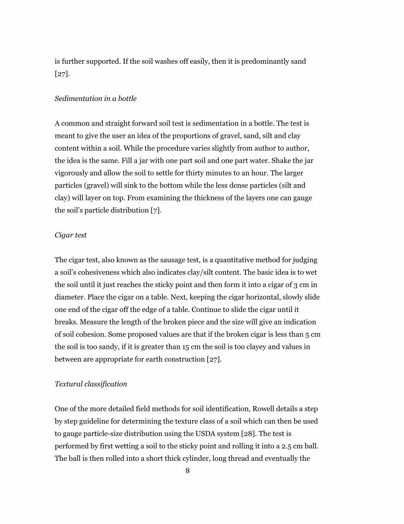
Sedimentation in a bottle
A common and straight forward soil test is sedimentation in a bottle. The test is
meant to give the user an idea of the proportions of gravel, sand, silt and clay
content within a soil. While the procedure varies slightly from author to author,
the idea is the same. Fill a jar with one part soil and one part water. Shake the jar
vigorously and allow the soil to settle for thirty minutes to an hour. The larger
particles (gravel) will sink to the bottom while the less dense particles (silt and
clay) will layer on top. From examining the thickness of the layers one can gauge
the soil’s particle distribution [7].
Cigar test
The cigar test, also known as the sausage test, is a quantitative method for judging
a soil’s cohesiveness which also indicates clay/silt content. The basic idea is to wet
the soil until it just reaches the sticky point and then form it into a cigar of 3 cm in
diameter. Place the cigar on a table. Next, keeping the cigar horizontal, slowly slide
one end of the cigar off the edge of a table. Continue to slide the cigar until it
breaks. Measure the length of the broken piece and the size will give an indication
of soil cohesion. Some proposed values are that if the broken cigar is less than 5 cm
the soil is too sandy, if it is greater than 15 cm the soil is too clayey and values in
between are appropriate for earth construction [27].
Textural classification
One of the more detailed field methods for soil identification, Rowell details a step
by step guideline for determining the texture class of a soil which can then be used
to gauge particle-size distribution using the USDA system [28]. The test is
performed by first wetting a soil to the sticky point and rolling it into a 2.5 cm ball.
The ball is then rolled into a short thick cylinder, long thread and eventually the
8
thread is formed into a ring. Throughout the process the soil is inspected for
cracking and if any of the tasks cannot be completed then the soil is thereby
identified. There are twelve levels of identification ranging from sand to loam to
clay with variations in between.
Drop test
The drop test is a qualitative method for gauging water content of a soil-water
mixture. It is performed by taking a ball of the mixed soil and dropping it onto a
hard surface from a height of approximately one meter. If the ball smashes like a
pancake then it has too much water. If the ball disintegrates upon impact or breaks
into many small pieces then it does not have enough water. If the ball splits into
three or four large pieces then it is at the optimum moisture content (OMC) [29].
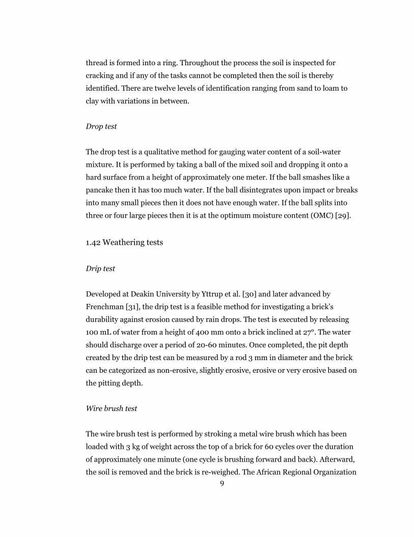
1.42 Weathering tests
Drip test
Developed at Deakin University by Yttrup et al. [30] and later advanced by
Frenchman [31], the drip test is a feasible method for investigating a brick’s
durability against erosion caused by rain drops. The test is executed by releasing
100 mL of water from a height of 400 mm onto a brick inclined at 27°. The water
should discharge over a period of 20-60 minutes. Once completed, the pit depth
created by the drip test can be measured by a rod 3 mm in diameter and the brick
can be categorized as non-erosive, slightly erosive, erosive or very erosive based on
the pitting depth.
Wire brush test
The wire brush test is performed by stroking a metal wire brush which has been
loaded with 3 kg of weight across the top of a brick for 60 cycles over the duration
of approximately one minute (one cycle is brushing forward and back). Afterward,
the soil is removed and the brick is re-weighed. The African Regional Organization 9

for Standardization (ARSO) recommends that for a one story dwelling exposed to
weathering the percentage loss of mass should not exceed 10% [32].
1.43 Strength tests
3-Point bending
Proposed by Morel & Pkla, the 3-point bending test is the only field method for
quantitatively determining the compressive strength of a brick [10]. Depicted in
Figure 1, execution of the test is analogous to that of a laboratory controlled 3-
point bending test and the compressive stress at failure is calculated using
Equation 1 which only relies on knowledge regarding brick geometry and the
applied force P.
𝜎𝜎𝑐𝑐 = 𝑃𝑃4ℎ𝑙𝑙
�1 + 𝐿𝐿4𝑒𝑒2
(1)
where
𝜎𝜎𝑐𝑐: Compressive strength
𝑃𝑃: Force of the applied weight
𝑙𝑙: Width of the test brick
𝐿𝐿: Distance between bottom support bars
𝑒𝑒: Distance between bottom and top bars
2ℎ: Thickness of the arch
This approach to compressive strength is
considered an indirect method because it is not
derived from classical Strength of Materials
theory �⃑�𝜎 = 𝑀𝑀𝑦𝑦�⃑𝐼𝐼
. In short, the authors claim that
the compressive stress is primarily transmitted to
the lower support bars through an arch effect Figure 1: 3-point bending test.
10
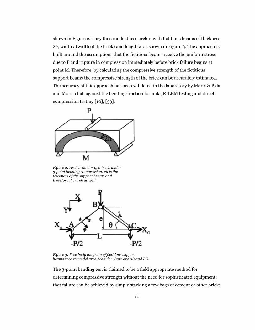
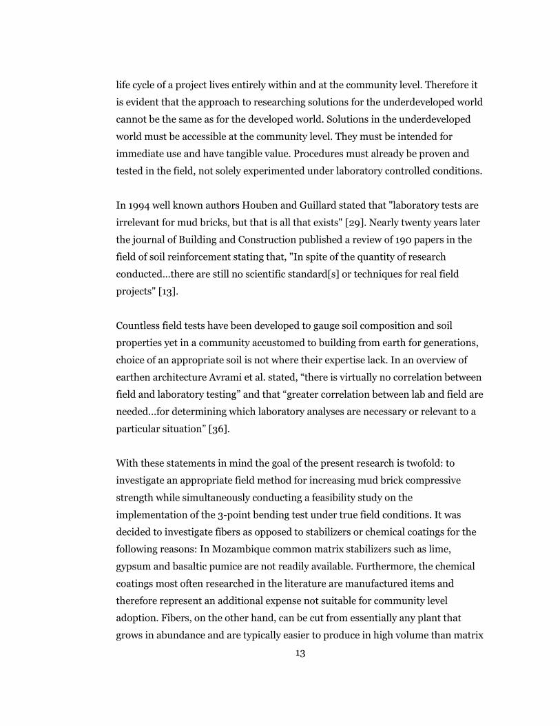
shown in Figure 2. They then model these arches with fictitious beams of thickness
2ℎ, width 𝑙𝑙 (width of the brick) and length λ as shown in Figure 3. The approach is
built around the assumptions that the fictitious beams receive the uniform stress
due to P and rupture in compression immediately before brick failure begins at
point M. Therefore, by calculating the compressive strength of the fictitious
support beams the compressive strength of the brick can be accurately estimated.
The accuracy of this approach has been validated in the laboratory by Morel & Pkla
and Morel et al. against the bending-traction formula, RILEM testing and direct
compression testing [10], [33].
Figure 2: Arch behavior of a brick under 3-point bending compression. 2h is the thickness of the support beams and therefore the arch as well.
Figure 3: Free body diagram of fictitious support beams used to model arch behavior. Bars are AB and BC. The 3-point bending test is claimed to be a field appropriate method for
determining compressive strength without the need for sophisticated equipment;
that failure can be achieved by simply stacking a few bags of cement or other bricks
11

for the applied load [10], [33]. However, there is yet to be any work documenting
its implementation in the field. The present study intends to fill this gap.
1.5 Current State of Earth Construction
The field of earth construction finds itself as the focus for the solution of two
equally important problems: creating dependable housing for the impoverished of
underdeveloped countries and enabling sustainable growth in developed countries
with booming development and finite resources. In the latter there has been an
abundance of successful research including studies in foundation engineering,
airstrip and helipad design, earthquake engineering, railway embankments and
building masonry [12], [13], [14], [24], [26], [34], [35]. In the former, however,
research has been stagnant and unapproached. What disassociates the two fields is
not their ultimate goal; each field works toward the improvement of soil
reinforcement. Instead, what separates them is the manner in which this goal can
be achieved and the way in which it must be pursued.
In developed nations earth construction is a solution for the future. If
implemented, it will be supported through organized funding and production.
Materials will be quality controlled and labor will be executed by trained
professionals. With an intended use and implementation of this nature, it is
perfectly acceptable that all research supporting earth construction is performed
within laboratories under fastidiously controlled conditions. However, this
laboratory focused approach does not suffice and is not applicable to
underdeveloped nations.
For the millions currently living in earth built homes, earth construction is not a
potential solution for the future in which the weaknesses can be meticulously
studied in laboratories for improvement. It is quite the opposite. Earth
construction is an everyday means to survival. It is the way in which families build
homes and often the only option available to them. Techniques are those which
have been passed down through generations of experimentation, materials and
tools are sparse and access to financial or human capital is often nonexistent. The 12
life cycle of a project lives entirely within and at the community level. Therefore it
is evident that the approach to researching solutions for the underdeveloped world
cannot be the same as for the developed world. Solutions in the underdeveloped
world must be accessible at the community level. They must be intended for
immediate use and have tangible value. Procedures must already be proven and
tested in the field, not solely experimented under laboratory controlled conditions.
In 1994 well known authors Houben and Guillard stated that "laboratory tests are
irrelevant for mud bricks, but that is all that exists" [29]. Nearly twenty years later
the journal of Building and Construction published a review of 190 papers in the
field of soil reinforcement stating that, "In spite of the quantity of research
conducted...there are still no scientific standard[s] or techniques for real field
projects" [13].
Countless field tests have been developed to gauge soil composition and soil
properties yet in a community accustomed to building from earth for generations,
choice of an appropriate soil is not where their expertise lack. In an overview of
earthen architecture Avrami et al. stated, “there is virtually no correlation between
field and laboratory testing” and that “greater correlation between lab and field are
needed...for determining which laboratory analyses are necessary or relevant to a
particular situation” [36].
With these statements in mind the goal of the present research is twofold: to
investigate an appropriate field method for increasing mud brick compressive
strength while simultaneously conducting a feasibility study on the
implementation of the 3-point bending test under true field conditions. It was
decided to investigate fibers as opposed to stabilizers or chemical coatings for the
following reasons: In Mozambique common matrix stabilizers such as lime,
gypsum and basaltic pumice are not readily available. Furthermore, the chemical
coatings most often researched in the literature are manufactured items and
therefore represent an additional expense not suitable for community level
adoption. Fibers, on the other hand, can be cut from essentially any plant that
grows in abundance and are typically easier to produce in high volume than matrix
13
stabilizers which often entail pulverizing an initially dense material into fine
particle distributions. Furthermore, fibers can be controlled in both fiber fraction
and fiber length which allows for a more detailed analysis ultimately creating
greater opportunity for insight into any results that may be attained. Therefore in
the present study bamboo and straw were chosen as reinforcing fibers. Both plants
grow prodigiously in Mozambique and also serve as appropriate contrasts to each
other. Bamboo has a much stronger compressive and tensile strength than straw
while also possessing a rougher fiber surface which contributes to increased shear
strength at the fiber-matrix interface. Finally, the current literature lacks research
concerning bamboo’s field use in soil bricks and is inconclusive regarding that of
straw. To contribute to this knowledge composite bricks were produced containing
fibers cut in lengths of 3 cm and 6 cm to evaluate the effect of fiber length. Fibers
were added in weights of 0.125%, 0.25% and 0.50% to further investigate the lower
bounds of fiber fractions. All results were compared to baseline bricks which did
not include any reinforcing fibers whatsoever.
14
Chapter 2
Materials & Methods
2.1 Traditional Brick Production
The traditional brick making method in Mozambique only utilizes two tools, a
garden hoe for digging and a wooden mold for brick formation (Figure 9). A
garden hoe is chosen strictly due to availability of tools. Once a soil is dug the
water is added directly at the digging site and mixed using the garden hoe and the
stomping of feet. The water content is controlled qualitatively through texture but
in essence is added until a maximum soil workability is achieved. There is not
much attention paid to oversaturation of the soil. After the water and soil have
been mixed bricks are formed using the wooden mold and laid out in the sun to
dry. In a four man team a full day’s work can produce up to 1,000 bricks. A mason
may also be hired to make bricks at a wage of 1 metical/brick (3¢/brick). In
Mozambique mixing fibers or other matrix stabilizers was not observed.
Throughout the current study effort was made to follow the traditional brick
making process. Only a garden hoe was used for digging and a locally made
wooden mold was used to form the bricks. As an extra precaution a soil sieve was
created to facilitate fiber mixing. The water content was controlled using the drop
test.
15
2.2 Experimental Materials
2.11 Soil
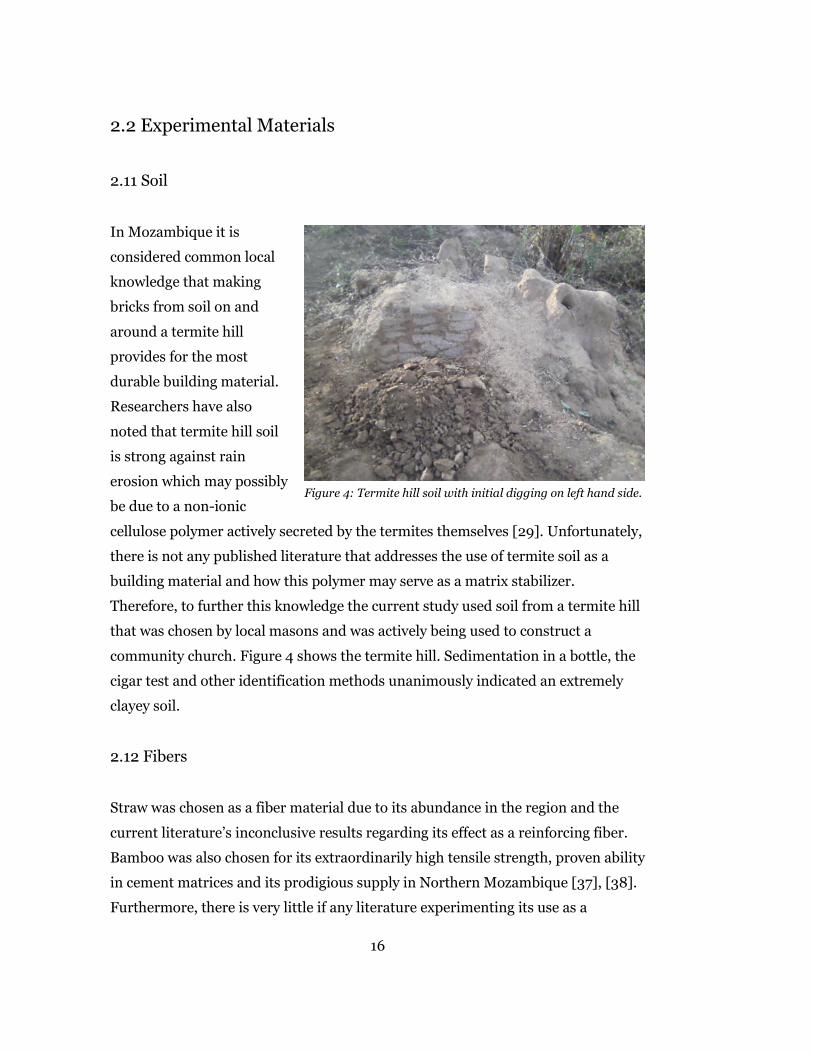
In Mozambique it is
considered common local
knowledge that making
bricks from soil on and
around a termite hill
provides for the most
durable building material.
Researchers have also
noted that termite hill soil
is strong against rain
erosion which may possibly
be due to a non-ionic
cellulose polymer actively secreted by the termites themselves [29]. Unfortunately,
there is not any published literature that addresses the use of termite soil as a
building material and how this polymer may serve as a matrix stabilizer.
Therefore, to further this knowledge the current study used soil from a termite hill
that was chosen by local masons and was actively being used to construct a
community church. Figure 4 shows the termite hill. Sedimentation in a bottle, the
cigar test and other identification methods unanimously indicated an extremely
clayey soil.
2.12 Fibers
Straw was chosen as a fiber material due to its abundance in the region and the
current literature’s inconclusive results regarding its effect as a reinforcing fiber.
Bamboo was also chosen for its extraordinarily high tensile strength, proven ability
in cement matrices and its prodigious supply in Northern Mozambique [37], [38].
Furthermore, there is very little if any literature experimenting its use as a
Figure 4: Termite hill soil with initial digging on left hand side.
16

reinforcing fiber in soil bricks and was therefore chosen here. Attempts were made
to choose stalks of both straw and bamboo similar in age since this can affect the
plants cellular make up and mechanical properties [19].
2.2 Specimen Production
2.21 Fibers
Straw
Upon gathering straw the
top and bottom of the stalks
were cut to remove grains,
roots and facilitate
uniformity in fiber
diameter. Any blades and
sheathes were also removed
leaving the bare stalks. In
order to remove the blades
and sheathes with
maximum efficiency a local
Mozambican hand tool that
resembles a three pronged
fork was utilized and is
depicted in Figure 5. The
hand tool is made by taking
a short piece of bamboo and
splitting the top half into
three pieces. Stones or
other dense material is then
wedged in between the
prongs to create separation. To remove the blades and sheathes a bundle of straw
is held vertically and quickly combed up and down with the fork until clean. This
Figure 6: Three pronged fork made from bamboo and used toclean straw of blades and sheathes.
Figure 5: Cutting straw fibers.
17

method proved incredibly efficient and did not damage the actual stalk of the
straw. Any leftover material was removed by hand until the stalk was completely
bare.
Upon cleaning the straw stalk, fibers were then cut using a ruler, scissors and large
bucket as shown in Figure 6. Fibers were cut in lengths of 3 cm and 6 cm with an
average diameter of 0.3 cm. It was found that cutting stalks in groups of three
minimized time without losing accuracy or being too rigid for the scissors to
penetrate. Using a machete was also experimented for cutting the straw into fibers.
While this method increased the number of stalks cut at a time it led to inaccurate
fiber lengths and many fibers being catapulted into the distance and lost,
ultimately deeming the method inefficient.
Bamboo
Bamboo was gathered, cleaned and cut for uniformity analogous to the straw
stalks. To create the fibers the bamboo stems were first cut into pieces of
approximately 1 meter in length. Afterward, the stems were spliced longitudinally
creating two halves. This process was continued until individual sticks of bamboo
sufficiently thin for fiber cutting were created. The bamboo fibers were then made
by cutting the bamboo sticks in 6 cm lengths. Due to bamboo’s inherently higher
compressive strength as a material, scissors could not be used to cut the fibers and
a bench grinder was utilized. For safety reasons this method did not permit
bamboo to be cut in fiber lengths of 3 cm. The average diameter of the bamboo
fibers was 0.24 cm.
18
2.22 Composite Bricks
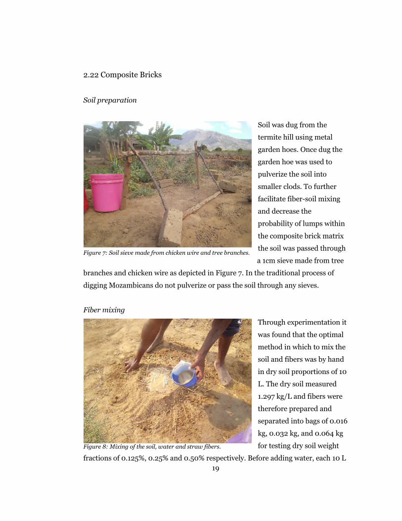
Soil preparation
Soil was dug from the
termite hill using metal
garden hoes. Once dug the
garden hoe was used to
pulverize the soil into
smaller clods. To further
facilitate fiber-soil mixing
and decrease the
probability of lumps within
the composite brick matrix
the soil was passed through
a 1cm sieve made from tree
branches and chicken wire as depicted in Figure 7. In the traditional process of
digging Mozambicans do not pulverize or pass the soil through any sieves.
Fiber mixing
Through experimentation it
was found that the optimal
method in which to mix the
soil and fibers was by hand
in dry soil proportions of 10
L. The dry soil measured
1.297 kg/L and fibers were
therefore prepared and
separated into bags of 0.016
kg, 0.032 kg, and 0.064 kg
for testing dry soil weight
fractions of 0.125%, 0.25% and 0.50% respectively. Before adding water, each 10 L
Figure 8: Mixing of the soil, water and straw fibers.
Figure 7: Soil sieve made from chicken wire and tree branches.
19

volume of soil was mixed by hand in a large bucket with the appropriate fiber
weight for a given test. The dry materials were mixed until a general uniformity
was achieved. Afterward the dry materials were poured out and the soil-fiber
mixture was formed into a volcano as seen in Figure 8. Water was then slowly
poured inside the crater of the volcano while being mixed and kneaded thoroughly
by hand with constant attention paid to the homogeneity of both the soil-fiber
mixture and the soil-water mixture.
During preliminary experimentation it was found that the maximum dry density
(MDD) of the soil corresponded to an optimum moisture content (OMC) of 20%.
Soil samples at the OMC were then subjected to the drop test in order to record
their behavior upon impact. This analysis allowed the drop test to be used on each
soil mixture during field testing to confirm water content before forming the brick.
An outline of the experimental details used for calculating the MDD and OMC can
be found in Appendix A.
Brick formation
Upon achieving an appropriate composite mixture, bricks were formed using the
wooden hand mold shown in Figure 9. The composite mixture was filled into the
mold and compacted by hand with attention paid to the corners of the mold. Once
the mold was full, a wet hand was used to softly brush and smooth over the
exposed surface of the composite mixture. To form the bricks the mold is carefully
laid face down on a flat surface and then slowly lifted up leaving the formed brick
while taking care not to stretch the brick upon release.
Throughout the entire process the brick mold should be kept submerged in clean
water while not in use. After forming each brick the mold needs to be rinsed
thoroughly with clean water, removing all leftover mud. Failure to do either of
these will cause the newly formed brick to stick to the mold upon exit and sustain
deformations when formed.
20
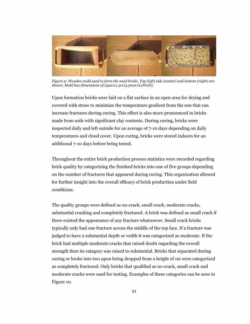
Figure 9: Wooden mold used to form the mud bricks. Top (left) side (center) and bottom (right) are shown. Mold has dimensions of 232x111.5x113.5mm (LxWxH).
Upon formation bricks were laid on a flat surface in an open area for drying and
covered with straw to minimize the temperature gradient from the sun that can
increase fractures during curing. This effect is also more pronounced in bricks
made from soils with significant clay contents. During curing, bricks were
inspected daily and left outside for an average of 7-10 days depending on daily
temperatures and cloud cover. Upon curing, bricks were stored indoors for an
additional 7-10 days before being tested.
Throughout the entire brick production process statistics were recorded regarding
brick quality by categorizing the finished bricks into one of five groups depending
on the number of fractures that appeared during curing. This organization allowed
for further insight into the overall efficacy of brick production under field
conditions.
The quality groups were defined as no-crack, small crack, moderate cracks,
substantial cracking and completely fractured. A brick was defined as small crack if
there existed the appearance of any fracture whatsoever. Small crack bricks
typically only had one fracture across the middle of the top face. If a fracture was
judged to have a substantial depth or width it was categorized as moderate. If the
brick had multiple moderate cracks that raised doubt regarding the overall
strength then its category was raised to substantial. Bricks that separated during
curing or broke into two upon being dropped from a height of 1m were categorized
as completely fractured. Only bricks that qualified as no-crack, small crack and
moderate cracks were used for testing. Examples of these categories can be seen in
Figure 10.
21

Figure 10: The classification of brick quality. A no-crack brick (left), a small crack brick (center) and a moderate crack brick (right).
It was found that brick strength did decrease as the quantity of cracks increased,
however, the decrease in strength was not significant. It was also observed that the
total number of usable bricks increased substantially with the use of fibers.
Complete results are listed in Table 1 of Chapter 3.
2.23 Experimental Setup
3-point bending test apparatus
The 3-point bending test is referenced in the literature as an easy field method for
calculating the compressive strength of a brick using simple weights such as other
bricks or bags of cement [27], [10]. It is said that by using this method compressive
strength can be found with an applied force 80-150 times less than what is needed
for failure under uniform compression [33]. In congruence with these statements
initial trials of the 3-point bending test were done according to the diagram in
Figure 11. The bottom support bars and the top load bearing bar were made from
steel rebar donated by a local road construction team. The steel rebar had a
diameter of 10 mm and the applied weight P was provided by stacking other mud
bricks on top of the test brick as depicted in Figure 11. Unfortunately, initial
attempts revealed that this simple approach would be unable to produce
22

repeatable results given the high force
requirements for testing these bricks.
One principal issue was the inability to
balance the applied weight on the top
bar. Individual bricks cannot be stacked
sufficiently high to supply the necessary
compressive force without tipping and
adding additional contact forces to the
test brick. To remedy this and following
additional guidelines from the literature,
a plate was placed on the top bar to allow
for stacking a column of bricks. For
additional support, guide wires were also
connected to the plate in an attempt to
maintain its balance during loading.
However, once again the instability of the
applied weight was an issue and in no way was this simplistic approach to the 3-
point bending test realistic. Finally, using the common value of 2 𝑁𝑁𝑚𝑚𝑚𝑚2 for hand
formed mud bricks and an average weight of 6 kg/brick it is straightforward to
determine that it would be necessary to stack upwards of 50-60 bricks in order to
achieve failure. Therefore through rudimentary testing it has been thoroughly
concluded that the straightforward approach proposed for the 3-pont bending test
in field applications is not feasible.
Construction of the lever system
To remedy the aforementioned issues it was decided to construct a lever system
that would apply the load P. The use of a lever not only increases the stability of
our applied load but it also allows for a lower external force when the equivalence
of lever moments is utilized. With the presumption of forces being applied
perpendicular to moment arms, the force applied to the test brick becomes
Figure 11: First iteration of the 3-point bending test.
23
proportional to the ratio of 𝑟𝑟1𝑟𝑟𝑝𝑝
as defined in Figure 12. Therefore the longer the
lever arm is, the lower the external force necessary to reach brick failure.
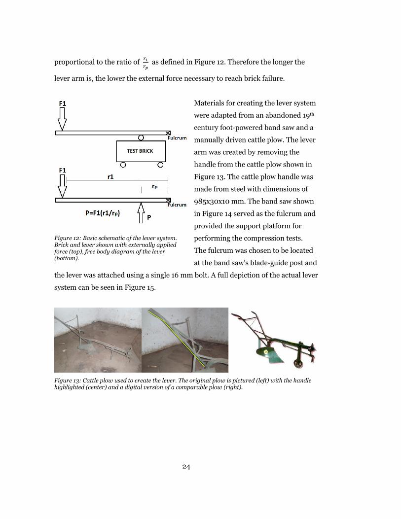
Materials for creating the lever system
were adapted from an abandoned 19th
century foot-powered band saw and a
manually driven cattle plow. The lever
arm was created by removing the
handle from the cattle plow shown in
Figure 13. The cattle plow handle was
made from steel with dimensions of
985x30x10 mm. The band saw shown
in Figure 14 served as the fulcrum and
provided the support platform for
performing the compression tests.
The fulcrum was chosen to be located
at the band saw’s blade-guide post and
the lever was attached using a single 16 mm bolt. A full depiction of the actual lever
system can be seen in Figure 15.
Figure 13: Cattle plow used to create the lever. The original plow is pictured (left) with the handle highlighted (center) and a digital version of a comparable plow (right).
Figure 12: Basic schematic of the lever system. Brick and lever shown with externally applied force (top), free body diagram of the lever (bottom).
24

Figure 14: 19th century foot-powered band saw used as fulcrum and testing support platform. A digital image of a comparable 19th century band saw is pictured for clarity (left) [39] alongside the actual band saw used (center) and a photo of the blade-guide post with lever attached (right).
Lever system modifications
During initial test runs it was observed that the current lever could only support up
to two 20 L buckets which did not provide the force necessary to induce brick
failure. After analyzing materials available it was decided that the appropriate
method was to extend the current lever arm by utilizing the second handle to the
cattle plow. Due to the cattle plow’s symmetry the handles were able to be attached
utilizing their original bolt pattern and were joined by two 14 mm bolts. Figure 16
depicts the new lever system and the bolts joining the two handles.
Figure 15: First iteration of 3-point bending lever system.
25
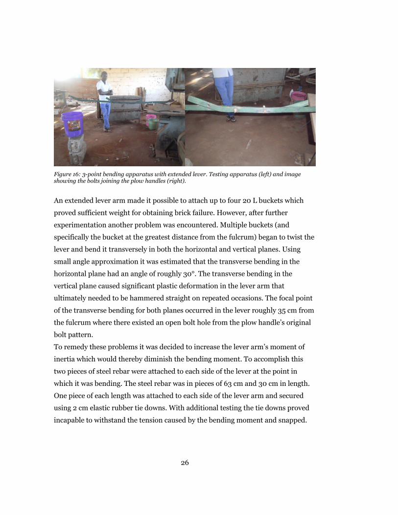
Figure 16: 3-point bending apparatus with extended lever. Testing apparatus (left) and image showing the bolts joining the plow handles (right).
An extended lever arm made it possible to attach up to four 20 L buckets which
proved sufficient weight for obtaining brick failure. However, after further
experimentation another problem was encountered. Multiple buckets (and
specifically the bucket at the greatest distance from the fulcrum) began to twist the
lever and bend it transversely in both the horizontal and vertical planes. Using
small angle approximation it was estimated that the transverse bending in the
horizontal plane had an angle of roughly 30°. The transverse bending in the
vertical plane caused significant plastic deformation in the lever arm that
ultimately needed to be hammered straight on repeated occasions. The focal point
of the transverse bending for both planes occurred in the lever roughly 35 cm from
the fulcrum where there existed an open bolt hole from the plow handle’s original
bolt pattern.
To remedy these problems it was decided to increase the lever arm’s moment of
inertia which would thereby diminish the bending moment. To accomplish this
two pieces of steel rebar were attached to each side of the lever at the point in
which it was bending. The steel rebar was in pieces of 63 cm and 30 cm in length.
One piece of each length was attached to each side of the lever arm and secured
using 2 cm elastic rubber tie downs. With additional testing the tie downs proved
incapable to withstand the tension caused by the bending moment and snapped.
26
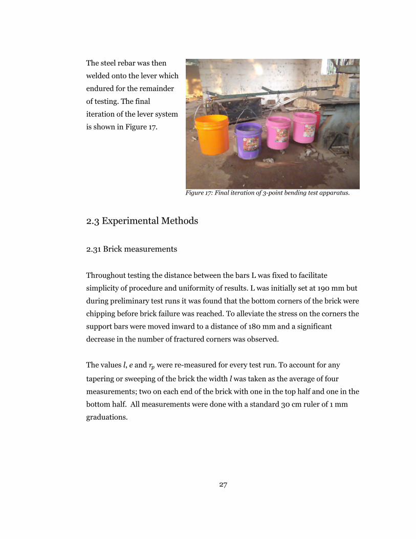
The steel rebar was then
welded onto the lever which
endured for the remainder
of testing. The final
iteration of the lever system
is shown in Figure 17.
2.3 Experimental Methods
2.31 Brick measurements
Throughout testing the distance between the bars L was fixed to facilitate
simplicity of procedure and uniformity of results. L was initially set at 190 mm but
during preliminary test runs it was found that the bottom corners of the brick were
chipping before brick failure was reached. To alleviate the stress on the corners the
support bars were moved inward to a distance of 180 mm and a significant
decrease in the number of fractured corners was observed.
The values l, e and 𝑟𝑟𝑝𝑝 were re-measured for every test run. To account for any
tapering or sweeping of the brick the width l was taken as the average of four
measurements; two on each end of the brick with one in the top half and one in the
bottom half. All measurements were done with a standard 30 cm ruler of 1 mm
graduations.
Figure 17: Final iteration of 3-point bending test apparatus.
27

2.32 Applying load P
To apply the load buckets were attached to the lever at fixed distances and slowly
filled with known volumes of water. Filling the buckets with known volumes of
water allowed the applied force to be controlled in a straightforward manner while
only using material readily available in the majority of field conditions.
During testing the buckets were placed at distances of 𝑟𝑟1 = 513 𝑚𝑚𝑚𝑚, 𝑟𝑟2 =
863 𝑚𝑚𝑚𝑚, 𝑟𝑟3 = 1225 𝑚𝑚𝑚𝑚 and 𝑟𝑟4 = 1586 𝑚𝑚𝑚𝑚 as shown in Figure 17. Buckets were
attached in order of increasing distance from the fulcrum. The first two buckets
were pre-filled with 20 L of water and attached to the lever at distances of 513 mm
and 863 mm respectively. The first two buckets contributed respective stresses of
0.3787 𝑁𝑁𝑚𝑚𝑚𝑚2 and 0.6371 𝑁𝑁
𝑚𝑚𝑚𝑚2 at point P as calculated by Equation 1. The third
bucket was pre-filled with 5 L and increased in 5 L portions (0.226 𝑁𝑁𝑚𝑚𝑚𝑚2) until
failure was reached. If brick failure had still not been obtained the fourth bucket
was attached empty and filled in 2 L increments (0.117 𝑁𝑁𝑚𝑚𝑚𝑚2). Buckets were filled by
hand at a rate of approximately 2 L/min and if brick failure occurred then bucket
filling immediately stopped and volumes were recorded. This procedure varied
slightly and was altered as necessary based on failure trends of the given test being
performed. Bricks were also studied briefly upon failure for fiber distribution
within the matrix.
2.33 Calculating P
A free body diagram of the four bucket method is shown in Figure 18.
28
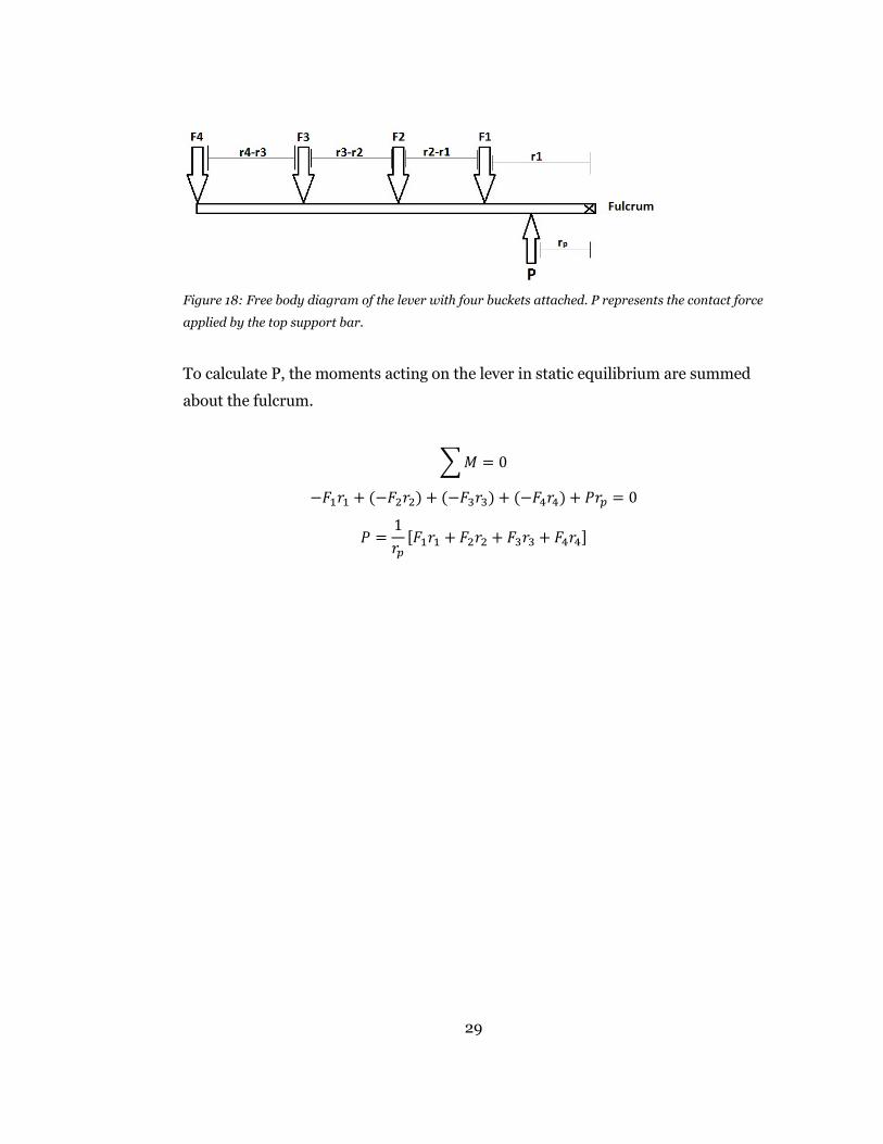
Figure 18: Free body diagram of the lever with four buckets attached. P represents the contact force
applied by the top support bar.
To calculate P, the moments acting on the lever in static equilibrium are summed
about the fulcrum.
�𝑀𝑀 = 0
−𝐹𝐹1𝑟𝑟1 + (−𝐹𝐹2𝑟𝑟2) + (−𝐹𝐹3𝑟𝑟3) + (−𝐹𝐹4𝑟𝑟4) + 𝑃𝑃𝑟𝑟𝑝𝑝 = 0
𝑃𝑃 =1𝑟𝑟𝑝𝑝
[𝐹𝐹1𝑟𝑟1 + 𝐹𝐹2𝑟𝑟2 + 𝐹𝐹3𝑟𝑟3 + 𝐹𝐹4𝑟𝑟4]
29

Chapter 3
Results & Conclusion
3.1 Results
Straw fibers were cut into lengths of 3 cm and 6 cm. The 3 cm straw fibers were
tested in fractions of 0.25% and 0.50% by weight of the dry soil while the 6 cm
straw fibers were only tested at 0.50% fiber fraction. The bamboo fibers were cut
in lengths of 6 cm and tested in fiber fractions of 0.125%, 0.25% and 0.50% by
weight. Unreinforced baseline bricks were also tested for a comparative
measurement.
3.11 Brick Production Quality
Table 1 shows quality measures for each type of brick produced. Usable bricks
include no-crack, small crack and moderate cracks. Unusable bricks include
substantial cracking and completely fractured.
30

Table 1: Brick production quality statistics for each type of composite produced.
Brick Type Number of
Samples
No-Crack
(%)
Total Usable
(%)
Total Unusable
(%)
BASELINE 105 39.14 57.57 42.42
0.25% 3 CM
STRAW 92 35.80 82.67 17.33
0.50% 3 CM
STRAW 40 55.21 85.40 14.59
0.50% 6 CM
STRAW 81 13.32 46.25 53.75
0.125% 6 CM
BAMBOO 80 29.45 72.15 27.85
0.25% 6 CM
BAMBOO 55 46 81 19
0.50% 6 CM
BAMBOO 58 32.93 77.48 22.52
In general, reinforcing fibers use their high tensile strengths to help distribute the
stresses transmitted by the brick matrix. For this reason reinforced bricks have
higher strain energy density and lower post-peak strength loss than unreinforced
bricks. As a consequence, during failure reinforced bricks demonstrate many small
fractures of limited size as opposed to very few fractures of substantial size [8].
Therefore, as fiber fractions increase the number of bricks categorized as unsuable
(substantially and completely fractured) should decrease. The results in Table 1
align with this conclusion
The unreinforced baseline bricks had 42.35% of its sample qualify as unusable due
to significant fracturing whereas fiber reinforced bricks as calculated from Table 1
averaged only 20.03%. Furthermore, of the 105 unreinforced bricks produced,
24.7% completely fractured during curing. For the 406 fiber reinforced bricks
produced, only 2.4% fractured during curing; two of which were from the 0.25% 3
cm straw bricks and eight from the 0.125% 6 cm bamboo bricks. Such a substantial
31
increase in usable brick production could greatly decrease labor time and give the
community member more opportunity for other projects.
It should be noted that these trends do not include results from the 0.50% 6 cm
straw bricks. These bricks consistently tested far below any other brick and as
shown in Table 1 less than half of their sample passed quality standards for testing.
Tables 2-4 show that these bricks also consistently performed incredibly poorly in
compression tests. Analyzing these bricks during and after production it seemed
possible that the composite’s fiber fraction reached a volumetric upper limit.
Further studies regarding the upper limits of fiber fractions as volumetric
proportions are recommended.
3.12 Compressive Strength
Tables 2-4 list the results for mean compressive strength in descending order for
all tests completed and are organized by brick quality. The compressive strength
was calculated to have an uncertainty of +/- 0.22-0.32 𝑁𝑁𝑚𝑚𝑚𝑚2. This uncertainty is
based in the propagation of uncertainties inherent in each of the measurements
needed for determining the variables in Equation 1. Methods for calculation
followed the customary partial derivative approach given by Holman [40]. P-
values for two tailed t-tests of 95% are also listed in Tables 2-4.
Table 2 lists values for no-crack bricks, Table 3 lists both no-crack and small crack
bricks while Table 4 lists values for all tested bricks. These groupings were chosen
to view the effects of brick fractures on compressive strength. Results show that as
expected increasing the number of brick fractures does lower the average
compressive strength but not by an extremely significant amount. Scatter plots
demonstrating the variation in brick compressive strength for Tables 2-4 can be
seen in Figures 19, 21 and 23 respectively. Bar graphs displaying the average
compressive strength for each testing sample can be seen in Figures 20, 22 and 24.
32

Table 2: Compressive strength of each composite calculated using no-crack bricks only.
Fibers Tested Number of
Samples
Mean Compressive
Strength (N/mm^2)
Standard
Deviation Two tailed P-values
BASELINE 36 1.9496 0.2606 n/a
0.25% 6 CM BAMBOO 23 1.8982 0.2773 0.485
0.125% 6 CM BAMBOO 27 1.8576 0.1959 0.120
0.25% 3 CM STRAW 24 1.8098 0.1881 0.021
0.50% 6 CM BAMBOO 12 1.7431 0.2809 0.038
0.50% 3 CM STRAW 16 1.6894 0.2770 0.003
0.50% 6 CM STRAW 5 1.4424 0.2780 0.012
33

Figure 19: Compressive strength of no-crack bricks.
0
0.5
1
1.5
2
2.5
3
0 5 10 15 20 25 30 35 40
Com
pres
sive
Str
engt
h N
/mm
^2
Specimen Count
Compressive Strength, No-Crack Bricks
Baseline Bricks
0.25% 3cm Straw
0.50% 3cm Straw
0.50% 6cm Straw
0.25% 6cm Bamboo
0.50% 6cm Bamboo
0.125% 6cm Bamboo
34
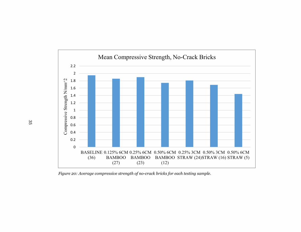
Figure 20: Average compressive strength of no-crack bricks for each testing sample.
0
0.2
0.4
0.6
0.8
1
1.2
1.4
1.6
1.8
2
2.2
BASELINE(36)
0.125% 6CMBAMBOO
(27)
0.25% 6CMBAMBOO
(23)
0.50% 6CMBAMBOO
(12)
0.25% 3CMSTRAW (24)
0.50% 3CMSTRAW (16)
0.50% 6CMSTRAW (5)
Com
pres
sive
Stre
ngth
N/m
m^2
Mean Compressive Strength, No-Crack Bricks
35

Table 3: Compressive strength of each composite calculated using no-crack and small crack bricks.
Fibers Tested Number of
Samples
Mean Compressive
Strength (N/mm^2)
Standard
Deviation Two tailed P-values
0.25% 6 CM BAMBOO 31 1.8803 0.2869 0.753
BASELINE 42 1.8581 0.3109 n/a
0.125% 6 CM BAMBOO 38 1.8049 0.2074 0.366
0.50% 6 CM BAMBOO 20 1.6876 0.2508 0.025
0.25% 3 CM STRAW 48 1.6581 0.2495 0.001
0.50% 3 CM STRAW 23 1.5691 0.3170 0.0009
0.50% 6 CM STRAW 17 1.1227 0.3275 1.24e-08
36

Figure 21: Compressive strength of no-crack and small crack bricks.
0
0.5
1
1.5
2
2.5
3
0 10 20 30 40 50 60
Com
pres
sive
Str
engt
h N
/mm
^2
Specimen Count
Compressive Strength, No-Crack & Small Crack Bricks
Baseline Bricks
0.25% 3cm Straw
0.50% 3cm Straw
0.50% 6cm Straw
0.25% 6cm Bamboo
0.50% 6cm Bamboo
0.125% 6cm Bamboo
37
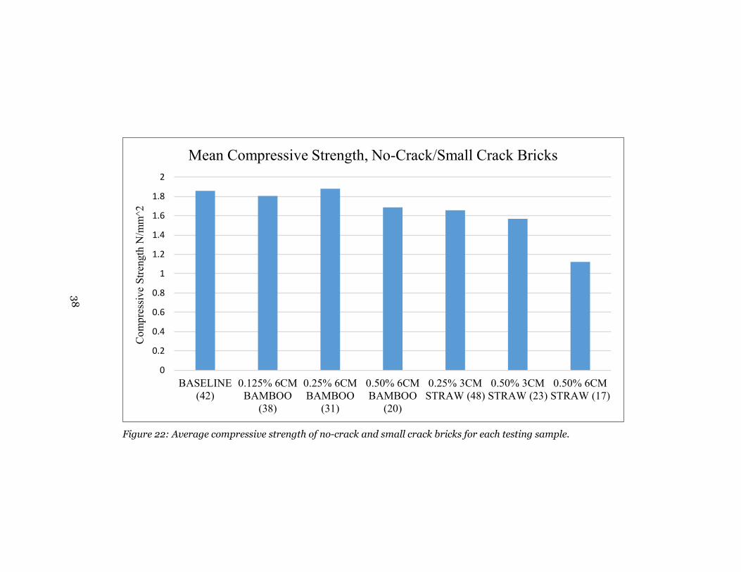
Figure 22: Average compressive strength of no-crack and small crack bricks for each testing sample.
0
0.2
0.4
0.6
0.8
1
1.2
1.4
1.6
1.8
2
BASELINE(42)
0.125% 6CMBAMBOO
(38)
0.25% 6CMBAMBOO
(31)
0.50% 6CMBAMBOO
(20)
0.25% 3CMSTRAW (48)
0.50% 3CMSTRAW (23)
0.50% 6CMSTRAW (17)
Com
pres
sive
Stre
ngth
N/m
m^2
Mean Compressive Strength, No-Crack/Small Crack Bricks
38
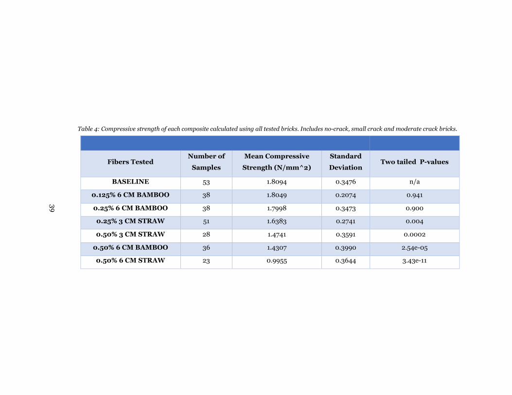
Table 4: Compressive strength of each composite calculated using all tested bricks. Includes no-crack, small crack and moderate crack bricks.
Fibers Tested Number of
Samples
Mean Compressive
Strength (N/mm^2)
Standard
Deviation Two tailed P-values
BASELINE 53 1.8094 0.3476 n/a
0.125% 6 CM BAMBOO 38 1.8049 0.2074 0.941
0.25% 6 CM BAMBOO 38 1.7998 0.3473 0.900
0.25% 3 CM STRAW 51 1.6383 0.2741 0.004
0.50% 3 CM STRAW 28 1.4741 0.3591 0.0002
0.50% 6 CM BAMBOO 36 1.4307 0.3990 2.54e-05
0.50% 6 CM STRAW 23 0.9955 0.3644 3.43e-11
39

Figure 23: Compressive strength of all bricks tested.
0
0.5
1
1.5
2
2.5
3
0 10 20 30 40 50 60Com
pres
sive
Str
engt
h N
/mm
^2
Specimen Count
Compressive Strength, All Tested Bricks
Baseline Bricks
0.25% 3cm Straw
0.50% 3cm Straw
0.50% 6cm Straw
0.25% 6cm Bamboo
0.50% 6cm Bamboo
0.125% 6cm Bamboo
40

Figure 24: Average compressive strength for all bricks in each testing sample.
0
0.2
0.4
0.6
0.8
1
1.2
1.4
1.6
1.8
2
BASELINE(53)
0.125% 6CMBAMBOO
(38)
0.25% 6CMBAMBOO
(38)
0.50% 6CMBAMBOO
(36)
0.25% 3CMSTRAW (51)
0.50% 3CMSTRAW (28)
0.50% 6CMSTRAW (23)
Com
pres
sive
Stre
ngth
N/m
m^2
Mean Compressive Strength, All Tested Bricks
41

Examining the tables many trends can be identified. The unreinforced baseline
bricks consistently attain the highest values for compressive strength regardless of
how the bricks are grouped. Bamboo fibers tend to produce a stronger composite
than straw but composite strength in general seems to fall with increasing fiber
fraction. This can be seen in all three tables in which bricks reinforced with
bamboo fiber fractions of 0.25% and below measured roughly equal to that of the
unreinforced brick. Compressive strength then fell as fiber fractions increased or
straw was introduced. However, as can be noted from the p-values all fiber
reinforced bricks that measured strengths comparable to the baseline bricks are
not statistically significant. Therefore the inclusion of bamboo fibers cannot
inconclusively be attributed with increasing or decreasing the composite’s
strength. Only the bricks that measured strengths much lower than the baseline
bricks produce p-values that demonstrate statistical significance, i.e. the fibers can
be attributed with the decrease in strength. A final observation as noted earlier is
that the 0.50% 6 cm straw fiber composite bricks repeatedly demonstrated
strength values well below that of any other composite.
These results contradict the conventional findings that reinforcing fibers increase
composite strength and lend evidence that under true field conditions reinforcing
fibers may actually be detrimental to brick strength. To analyze this it is necessary
to take a deeper look at the fiber-matrix interaction.
The failure of reinforcing fibers is governed by fiber pullout, fiber breakage and
localized deformations that can arise from non-uniform fiber distribution [13],
[41]. Fiber pullout is dictated by the shear strength at the fiber-matrix interface
which is directly related to fiber surface friction (fiber roughness), soil cohesion
and the difference in water absorption between the fiber and matrix during curing.
The present study was conducted using a very clayey soil which by definition has
strong soil cohesion properties and therefore was not the cause for weakness at the
interface. Furthermore, both straw and bamboo have sufficiently high moduli of
elasticity that fiber breakage can be ruled out. This was confirmed by inspecting
bricks that were successfully fractured during testing and not observing any
42
broken fibers. Instead, it is suspected that the main influence of composite
weakness was due to both the drying conditions and the nonhomogeneous mixing
of fibers.
When the matrix and fibers are mixed with water then set to dry they swell and
contract. The unequal rates of swelling and contracting between the matrix and
fibers can leave voids at the fiber-matrix interface. If the void is sufficiently large
(at the micro level) it is clear that there cannot be any shear force at the interface
creating perfect conditions for fiber pullout and slippage. Since bricks were left to
dry under climatic conditions they were constantly exposed to large fluctuations in
both humidity and air pressure which directly affects pore water pressure and
drying rate. This continuous fluctuation maintained the matrix and fibers in a
constant state of swelling and contracting all the way up to compression testing.
For this reason it was attempted to only test bricks after midday when any excess
moisture would have had a chance to evaporate. Finally, fiber pullout is also
related to the surface friction of the individual fiber material. Bamboo is inherently
a much rougher material than straw and would therefore have a higher value of
shear strength at the fiber-matrix interface which in turn better utilizes bamboo’s
high tensile strength. This was supported qualitatively by simply attempting to pull
an exposed fiber out of the dried brick matrix. The straw fiber only needed a slight
tug with two fingers and dislodged easily. The bamboo fiber could not be dislodged
even with the use of pliers. This difference may have been a contributing factor to
why bamboo reinforced bricks tested superior to straw reinforced bricks.
A significant problem with mixing fibers within the matrix is achieving a
homogeneous mixture. This difficulty exists in the laboratory and is exacerbated
under field conditions. The factors associated with non-homogeneous mixtures are
typically classified into the unequal distribution of fibers (clumping) and the
folding of fibers (balling) [13]. For more rigid fibers such as straw and bamboo,
folding is not a key issue but clumping is still pertinent. The clumping of fibers can
cause localized deformation planes which will reduce brick strength. To investigate
fiber clumping, bricks that were successfully fractured during compression testing
were inspected for fiber distribution. It was found that fiber clumping was
43

identifiable and there also seemed to be a horizontal preference to fiber
organization similar to that observed for fiber reinforced sands prepared by moist
tamping [42].
3.13 Feasibility of 3-point Bending Test
This study attempted to utilize the 3-point bending test as proposed by [10]. The 3-
point bending test is said to be a straightforward method for calculating brick
compressive strength under field conditions. Through extensive experimentation
the author did not find this to be true. The typical stress of 2 𝑁𝑁𝑚𝑚𝑚𝑚2 necessary to
fracture even hand compressed unreinforced mud bricks requires applied forces
far too large for simple application, especially when the applied weight must be
physically balanced upon a bar. To remedy these issues a lever system was
constructed that allowed for the necessary force to be applied. While this method
was sufficient in obtaining brick failure it is still impractical for field use. The lever
system requires a fulcrum of substantial strength that is impractical as a
requirement for field testing.
It is suggested to study the effects of water degradation on overall brick strength
and durability. After two years of living within a mud brick community the author
has concluded that dry compressive strength is not the principal mechanism
responsible for mud brick failure. It is the deterioration from rain weathering
coupled with a low compressive strength when wet that causes brick failure.
Natural elements such as rain change the physical composition of the mud brick
and must therefore be studied separately from the dry brick until a relationship
between dry strength and overall durability when wet is known. It is highly advised
to investigate brick erodiblity and fracture propagation under conditions of
moisture. It is also advised to define a method for testing a brick’s wet compressive
strength. Dry compressive strength is necessary to confirm that a brick has the
fundamental properties necessary for housing construction. Wet compressive
strength can demonstrate the variability of brick strength when exposed to
weathering and give a measure of the brick’s overall durability. It is already 44
advised in the literature that a brick should have a dry to wet compressive strength
ratio of two [8]. However, the criteria for wet is undefined and there still do not
exist exact methods for obtaining a wet brick under field conditions, nor has this
ratio been confirmed. A straightforward approach could be to immerse the brick in
water for a short amount of time and weigh it afterward. Continue this process
until the difference in consecutive weightings is less than 1%. Changes in brick
weight could also be recorded against dry weight to define a state of saturation.
Likewise compressive strength can be evaluated at each saturation level.
3.2 Conclusion
The present study was conducted in the village of Ribaue located in the Northern
Province Nampula of Mozambique. Composite mud bricks were produced using
highly clayey soil taken from an active termite hill and reinforced with straw and
bamboo fibers. Reinforcing fibers were cut in lengths of 3 cm and 6 cm and added
in fiber fractions by dry soil weight of 0.125%, 0.25% and 0.50%. Bricks were
produced and tested for compressive strength using an applications of the 3-point
bending test. Throughout the entire brick production process the composite bricks
were categorized by quality based on the number of fractures that appeared during
curing. During compression testing successfully fractured bricks were also
inspected for fiber breakage and fiber distribution. Based on experimental results
it has been concluded that:
• Under true field conditions reinforcing fibers do not increase composite
strength. Only a decrease was observed.
• Reinforcing fibers do add to the brick’s strain energy density which
decreases substantial fracturing during curing and ultimately increases
brick production efficiency
• Fiber breakage was not observed for bamboo or straw. Evidence for fiber
clumping and a preferred horizontal orientation was observed.
• The 3-point bending test as advised by the literature is not an appropriate
method for determining dry compressive strength under field conditions.
45

The field of earth construction as applied to community development in
underdeveloped nations is a unique discipline in that it requires innovative
solutions that can be implemented through simplistic means. The diverse
nonuniform conditions in which earth construction is practiced creates a demand
for direct field experimentation. The intricately prepared theoretically based
laboratory experiments must be traded out for a return to the true iteration and
prototype based methods that separate engineering from the pure sciences. The
applications of earth construction in rural communities are not as immediately
lucrative as those of applications in developed countries and therefore research
funding is more difficult to obtain. The general approach to research also involves
leaving the comfort and familiarity of controlled laboratory conditions for the
unpredictable, dynamic and unknown conditions of the field. However this is
where true engineering lives, in the heart of experimentation and in-situ
prototyping. Over half the world’s population live in homes built from unfired
earth and suffer the annual struggles of building deterioration due to weathering
and natural degradation. The inability to rely on the security of a home is one of
the roots of stagnated development and perpetual poverty. If one constantly needs
to spend time repairing something as fundamental to human civilization as the
home, then one cannot ever develop other aspects such as food security, health and
sanitation or steady income. For these reasons it is imperative that the focus of
academic research gives equal support to housing solutions in underdeveloped
countries.
46
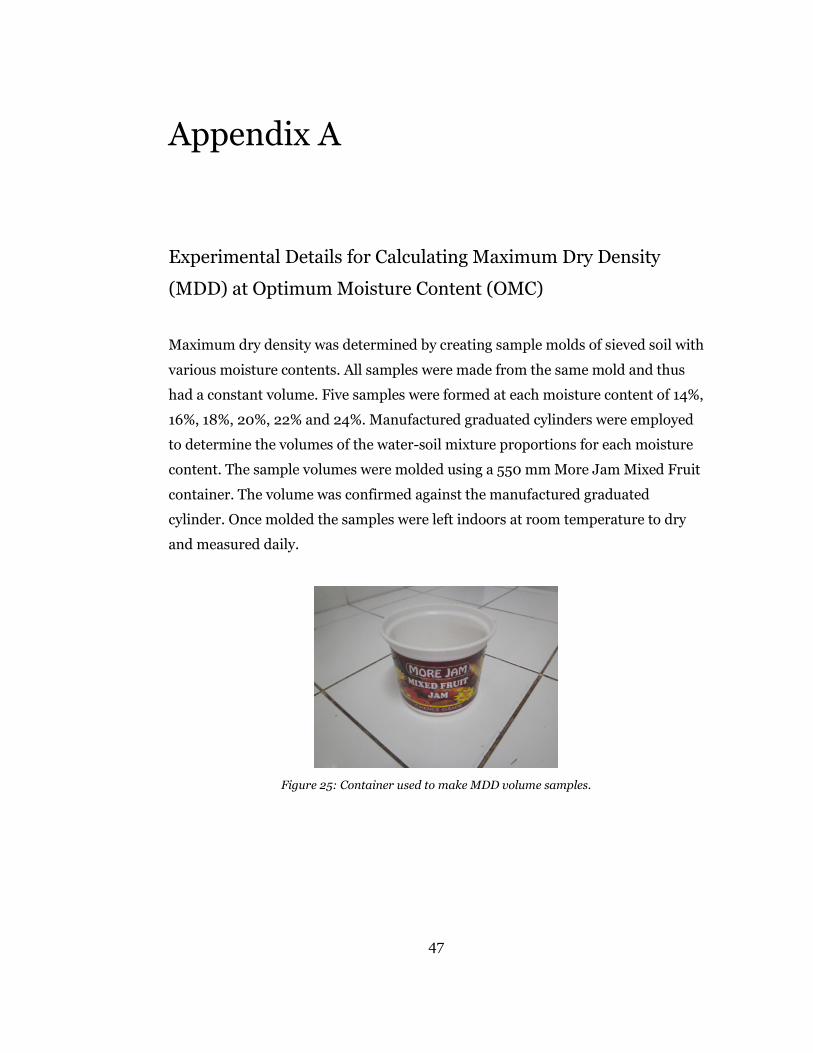
Appendix A
Experimental Details for Calculating Maximum Dry Density
(MDD) at Optimum Moisture Content (OMC)
Maximum dry density was determined by creating sample molds of sieved soil with
various moisture contents. All samples were made from the same mold and thus
had a constant volume. Five samples were formed at each moisture content of 14%,
16%, 18%, 20%, 22% and 24%. Manufactured graduated cylinders were employed
to determine the volumes of the water-soil mixture proportions for each moisture
content. The sample volumes were molded using a 550 mm More Jam Mixed Fruit
container. The volume was confirmed against the manufactured graduated
cylinder. Once molded the samples were left indoors at room temperature to dry
and measured daily.
Figure 25: Container used to make MDD volume samples.
47
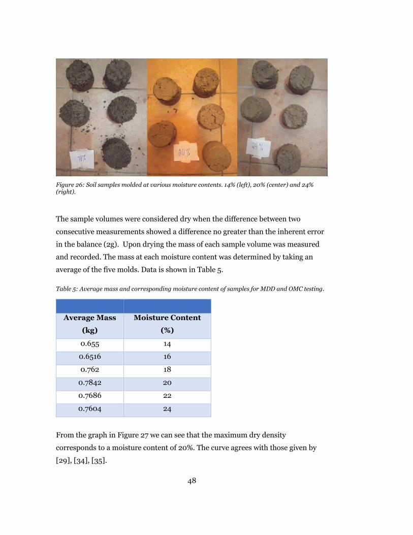
Figure 26: Soil samples molded at various moisture contents. 14% (left), 20% (center) and 24% (right).
The sample volumes were considered dry when the difference between two
consecutive measurements showed a difference no greater than the inherent error
in the balance (2g). Upon drying the mass of each sample volume was measured
and recorded. The mass at each moisture content was determined by taking an
average of the five molds. Data is shown in Table 5. Table 5: Average mass and corresponding moisture content of samples for MDD and OMC testing.
Average Mass
(kg)
Moisture Content
(%)
0.655 14
0.6516 16
0.762 18
0.7842 20
0.7686 22
0.7604 24
From the graph in Figure 27 we can see that the maximum dry density
corresponds to a moisture content of 20%. The curve agrees with those given by
[29], [34], [35].
48
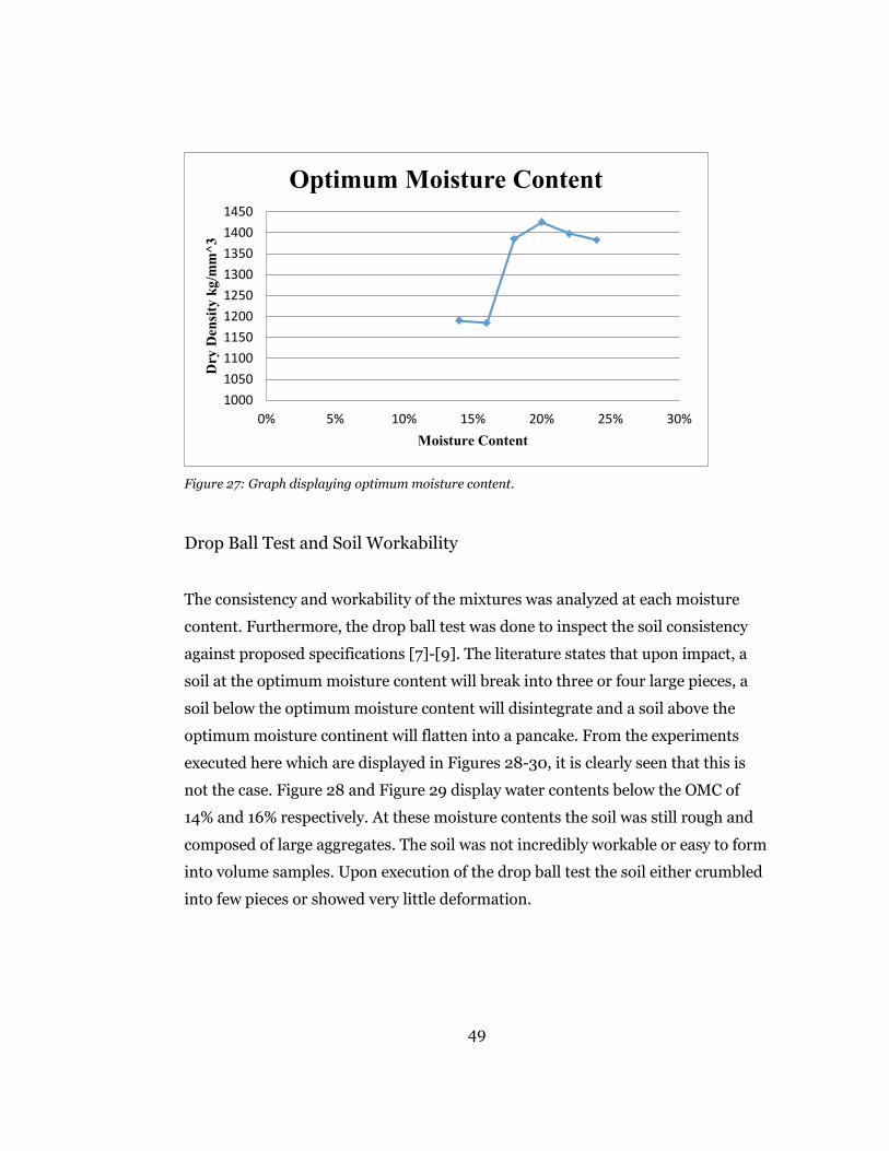
Figure 27: Graph displaying optimum moisture content.
Drop Ball Test and Soil Workability
The consistency and workability of the mixtures was analyzed at each moisture
content. Furthermore, the drop ball test was done to inspect the soil consistency
against proposed specifications [7]-[9]. The literature states that upon impact, a
soil at the optimum moisture content will break into three or four large pieces, a
soil below the optimum moisture content will disintegrate and a soil above the
optimum moisture continent will flatten into a pancake. From the experiments
executed here which are displayed in Figures 28-30, it is clearly seen that this is
not the case. Figure 28 and Figure 29 display water contents below the OMC of
14% and 16% respectively. At these moisture contents the soil was still rough and
composed of large aggregates. The soil was not incredibly workable or easy to form
into volume samples. Upon execution of the drop ball test the soil either crumbled
into few pieces or showed very little deformation.
1000105011001150120012501300135014001450
0% 5% 10% 15% 20% 25% 30%
Dry
Den
sity
kg/
mm
^3
Moisture Content
Optimum Moisture Content
49

Figure 28: Drop ball test at 14% moisture content.
At the optimum moisture content of 20% the soil mixture was smooth, very
workable and just near the sticky point. Contrary to the normative documents, the
drop ball test did not exhibit a ball that broke into three or four pieces but instead
showed a ball that flattened into a pancake. Furthermore, upon impact the ball
splattered and did not retain much form.
Figure 30: Drop ball test at an OMC of 20%.
Higher water contents such as 22% and 24% were overly moist soils that could be
described as ‘puddly’. Shown in Figure 31, the drop ball test for a soil at 24%
moisture content completely splattered upon impact. Also, the soils above the
OMC did not easily create volume samples. These soils were overly sticky and often
took excessive effort to remove from the mold. The impact necessary for extrusion
often deformed the volume sample. Some samples slouched upon removal.
Figure 29: Drop ball test at 16% moisture content.
50
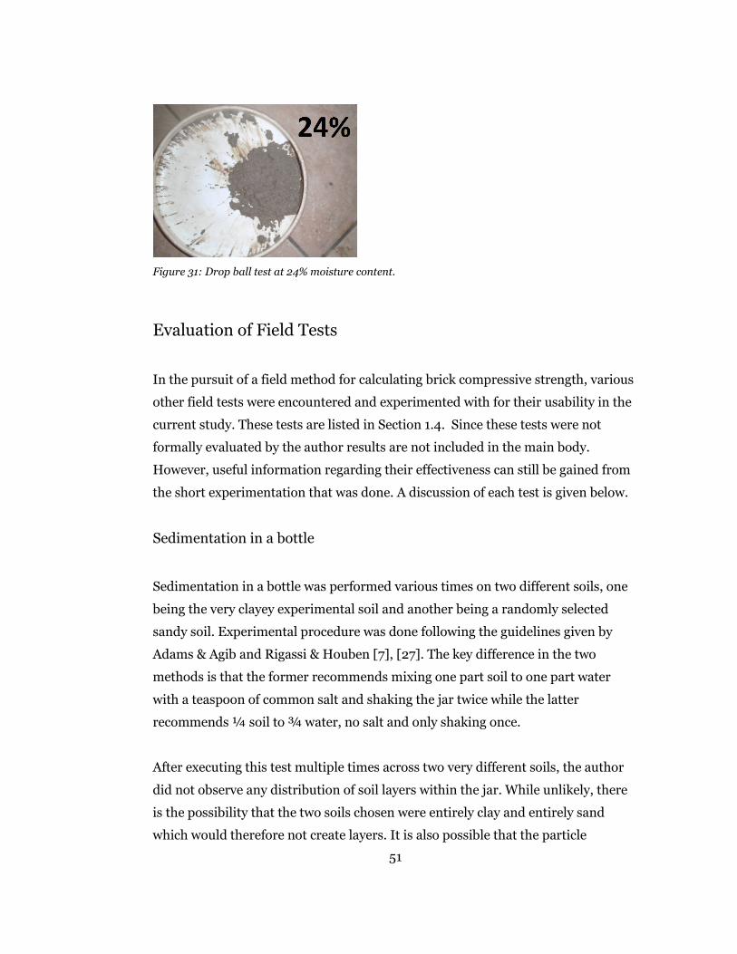
Figure 31: Drop ball test at 24% moisture content.
Evaluation of Field Tests
In the pursuit of a field method for calculating brick compressive strength, various
other field tests were encountered and experimented with for their usability in the
current study. These tests are listed in Section 1.4. Since these tests were not
formally evaluated by the author results are not included in the main body.
However, useful information regarding their effectiveness can still be gained from
the short experimentation that was done. A discussion of each test is given below.
Sedimentation in a bottle
Sedimentation in a bottle was performed various times on two different soils, one
being the very clayey experimental soil and another being a randomly selected
sandy soil. Experimental procedure was done following the guidelines given by
Adams & Agib and Rigassi & Houben [7], [27]. The key difference in the two
methods is that the former recommends mixing one part soil to one part water
with a teaspoon of common salt and shaking the jar twice while the latter
recommends ¼ soil to ¾ water, no salt and only shaking once.
After executing this test multiple times across two very different soils, the author
did not observe any distribution of soil layers within the jar. While unlikely, there
is the possibility that the two soils chosen were entirely clay and entirely sand
which would therefore not create layers. It is also possible that the particle
51
distribution bandwidth was small enough that a layer distribution was not
observable with the naked eye. These claims cannot be refuted without proper
laboratory equipment. In either scenario this test did not prove adequate as a field
method to determining particle distribution in a soil sample. It is possible that
sedimentation in a bottle is only applicable to soils with a large variant in particle
distribution.
Cigar test
The cigar tests was used to gauge soil cohesiveness which can then be used to
determine whether a soil has the appropriate silt/clay content for earth
construction. Rigassi & Houben [27] give the following broken piece lengths
• < 5 cm soil is too sandy
• > 15 cm soil is too clayey
• > 5 cm and < 15 cm soil is good
The cigar test was performed nine times on the experimental soil which was known
to be extremely clayey. Results from the cigar test successfully supported this and
are listed in the Table 6. During initial trials of the cigar test it was immediately
observed that the broken piece was not equal to the hanging piece. The cigar did
not break at the point from which it hung but instead separated further down. For
completeness both lengths are listed.
52

Table 6: Results from cigar test.
Hanging Length (cm) Broken Length (cm)
23 18 22 14 27 22 22 22 22 14 23 16 25 20 25 20 25 25
Average 23.7 19
While there does not exist any information in the literature regarding the direct
use of the cigar test and its implications for a strong building soil, preliminary tests
done by the author find the cigar test to be an appropriate field method for gauging
sand vs. clay content.
Wire brush test
The wire brush test was only performed once on a sample brick not made from the
experimental soil but from a different soil with a higher sand content. The
weighted wire brush was made by attaching 3 kg of assorted weights and using
electrical tape as shown in Figure 32.
Figure 32: Wire brush with 3kg of weight attached.
53

The mass of the brick was recorded before brushing to be 5.158 kg. The brick was
then brushed according to the procedure outlined by Adams & Agib [7] and re-
weighed afterward at 5.044 kg. Therefore the mass of detached matter as a
percentage of initial brick weight was calculated at 2.2%. An image of the brick
after brushing can be seen in Figure 33.
Figure 33: Mud brick after receiving the wire brush test.
The African Regional Organization for Standardization (ARSO) advises that one
story homes which are exposed to weather should not have a mass of detached
matter that exceeds 10%. From Figure 23 it can be clearly seen that the brick
suffered substantial damage from brushing even though it is well below the
advised percentage. Therefore it is recommended that the wire brush test be
formally evaluated experimentally and the suggested value of 10% confirmed.
Furthermore, other brush factors such as wire gauge and wire quantity are not
considered in the proposed test equations and could potentially play a significant
role in the percentage of detached matter.
Drip test
Shown in Figure 34, the drip test was executed by using a plastic water bottle with
a slight hole punctured in the cap from a sewing needle. The punctured hole and
cap tightness were adjusted as necessary to achieve a drip rate that released
54

100mL of water over a 20-60 minute interval. The test brick was elevated to
approximately 27° using another brick.
Figure 34: Experimental setup of drip test.
The drip test was performed numerous times on the experimental soil as well as
another soil of higher sand content. In both instances there was not any
measurable pit depth observed. Using Table 7 as proposed by Frenchman [31] the
test brick is rated as non-erosive. Without more experimentation the author
cannot make further claims regarding the drip test or these results. However, it
appears highly suspicious that a hand-pressed non-stabilized mud brick tests as
non-erosive. It is advised that the drip test be thoroughly evaluated.
Table 7: Drip test pit depth ratings.
Depth of pitting (mm) Rating
0 Non-erosive
0< and <5 Slightly erosive
5< and <10 Erosive
>10 Very erosive
55
References
[1] "Climate Change Knowledge Portal 2.0," The World Bank Group, 1900-2009.
[Online]. Available: http://sdwebx.worldbank.org/climateportal/index.cfm?page=
country_historical_climate&ThisRegion=Africa&ThisCCode=MOZ. [Accessed 27 April
2015].
[2] D. Bourdon, Designing the earth: the human impulse to shape nature, Harry N.
Abrams, Inc., 1995.
[3] B. Berge, The ecology of building materials, Burlington: Elsevier, Ltd., 2000.
[4] M. C. J. Delgado and I. C. Guerrero, "The selection of soils for unstabilised earth
building: A normative review," Construction and Building Materials, vol. 21, pp. 237-
251, 2007.
[5] F. Pacheco-Torgal and S. Jalali, "Earth construction: Lessons from the past for future
eco-effecient construction," Construction and Building Materials, vol. 29, pp. 512-
519, 2012.
[6] V. Maniatidis and P. Walker, "A Review for Rammed Earth Construction for DTi
Partners in Innovation Project for 'Developing Rammed Earth for UK Housing',"
University of Bath, 2003.
[7] E. A. Adam and A. R. A. Agib, Compressed Stabilised Earth Block Manufacture in
Sudan, Paris: United Nations Educational, Scientifc and Cultural Organization, 2001.
[8] Q. Piattoni, E. Quagliarini and S. Lenci, "Experimenal analysis and modelling of the
mechanical behaviour of earthern bricks," Construction and Building Materials, vol.
25, pp. 2067-2075, 2011.
[9] A. Uchaipichat, "Prediction of shear strength for unsaturated soils under drying and
wetting processes," Electronic Journal of Geotechnical Engineering, vol. 15, pp.
1087-1102, 2010.
56
[10] J. Morel and A. Pkla, "A model to measure compressive strength of compressed
earth blocks with the '3-point bending test'," Construction and Building Materials,
vol. 16, pp. 303-310, 2002.
[11] S. Yetgin, O. CAVDAR and A. Cavdar, "The effects of fiber contents on the mechanic
properties of the adobes," Constructio and Building Materials, vol. 22, pp. 222-227,
2008.
[12] K. V. Maheshwari, A. K. Desai and C. H. Solanki, "Performance of fiber reinforced
clayey soil," Electronic Journal of Geotechnical Engineering, vol. 16, pp. 1067-1082,
2011.
[13] S. M. Hejazi, M. Sheikhzadeh, S. M. Abtahi and A. Zadhoush, "A simple review of soil
reinforcement by using natural and synthetic fibers," Construction and Building
Materials, vol. 30, pp. 100-116, 2012.
[14] V. Mathur, "Composite materials from local resources," Construction and Building
Materials, vol. 20, pp. 470-477, 2006.
[15] K. Ghavami, R. D. Toledo and N. P. Barbosa, "Behaviour of composite soil reinforced
with natural fibers," Cement and Concrete Composites, vol. 21, pp. 39-48, 1999.
[16] A. Chegenizadeh and H. Nikraz, "Effective parameters on strength of reinforced
clayey sand," International Journal of Material Science, vol. 2, no. 1, pp. 1-5, 2012.
[17] H. Binici, O. Aksogan and T. Shah, "Investigation of fibre reinforced mud brick as a
building material," Construction and Building Materials, vol. 19, pp. 313-318, 2005.
[18] M. Bouhicha, F. Aouissi and S. Kenai, "Performance of composite soil reinforced
with barley straw," Construction and Building Materials, vol. 27, pp. 617-621, 2005.
[19] R. M. Rowell, J. S. Han and J. S. Rowell, "Characterization and factors effecting fiber
properties," in Natural Polymers and Agrofibers Composites, Sao Carlos, Brazil,
Embrapa Instrumentacao Agropecuaria, 2000, pp. 115-134.
[20] A. H. Heath, A Manual of Lime and Cement, London: William Clowes and Sons, 1893.
57

[21] H. Binici, O. Aksogan, D. Bakbak, H. Kaplan and B. Isik, "Sound insulation of fibre
reinforced mud brick walls," Construction and Building Materials, vol. 23, pp. 1053-
1041, 2009.
[22] E. A. Adam and P. J. Jones, "Thermophysical properites of stabilised soil building
blocks," Building and Environment, vol. 30, no. 2, pp. 245-253, 1995.
[23] A. Guettala, A. Abibsi and H. Houari, "Durability study of stabilized earth concrete
under both laboratory and climatic conditions exposure," Construction and Building
Materials, vol. 20, pp. 119-127, 2006.
[24] L. Turanli and A. Saritas, "Strengthening the structural behavior of adobe walls
through the use of plaster reinforcement mesh," Construction and Building
Materials, vol. 25, pp. 1747-1752, 2011.
[25] K. B. Ren and D. A. Kagi, "Upgrading the durability of mud bricks by impregnation,"
Building and Environment, vol. 30, no. 3, pp. 433-440, 1995.
[26] R. L. Santoni and S. L. Webster, "Airfields and roads construction using fiber
stabilization of sands," Journal of Transportation Engineering, vol. 127, pp. 96-104,
2001.
[27] V. Rigassi and H. Houben, Compressed Eath Blocks: Manual of Production,
Deutsches Zentrum fur Entwicklungstechnologien - GATE, 1995.
[28] D. L. Rowell, Soil Science: Methods & Applications, Essex: Longman Scientific &
Technical, 1994.
[29] H. Houben and H. Guillard, Earth Construction: A Comprehensive Guide, Practical
Action, 1994.
[30] P. J. Yttrup, K. Diviny and F. Sottile, "Development of a drip test for the erodability
of mud bricks," Deakin University, School of Architecture, 1981.
[31] G. J. Frenchman, "The performance of earth buildings," Deakin University, Geelong,
1982.
[32] S. Boubekeur and H. Houben, Compressed Earth Blocks Standards, Brussels: CDI,
CRATerre-EAG/ODA, 1998.
58
[33] J.-C. Morel, A. Pkla and P. Walker, "Compressive strength testing of compressed
earth blocks," Construction and Building Materials, vol. 21, pp. 303-309, 2007.
[34] A. Kumar, B. S. Walia and J. Mohan, "Compressive strength of fiber reinforced highly
compressible clay," Construction and Building Materials, vol. 20, pp. 1063-1068,
2006.
[35] J. K. Newman and D. J. White, "Rapid assessment of cement/fiber stabilized soil
using roller-integrated compaction monitoring," in Transportation Research Board
87th Annual Meeting, Washington D.C., 2008.
[36] E. Avrami, H. Guillaud and M. Hardy, Terra literature review: An overview of
research in earthen architecture conservation, Los Angeles: The Getty Conservation
Institute, 2008.
[37] H. S. Ramaswamy, B. M. Ahuja and S. Krishnamoorthy, "Behaviour of concrete
reinforced with jute, coir and bamboo fibers," International Journal of Cement
Composites and Lightweight Concrete, vol. 5, no. 1, pp. 3-13, 1983.
[38] L. Elizabeth and C. Adams, Alternative Construction: Contemporary Natural Building
Methods, Hoboken: John Wiley & Sons, 2005.
[39] Woodcraft: A Journal of Woodworking with Which is Incorporated the
Patternmaker, Vols. 9-11, 1908.
[40] J. P. Holman, Experimental Methods for Engineers, Tokyo: McGraw-Hill, 1971.
[41] C. Li, "Mechanical response of fiber-reinforced soil," Ph.D Dissertation, Dept. of
Mech. Eng., Univ. of Texas, Austin, TX, 2005.
[42] A. Diambra, A. R. Russell, E. Ibraim and D. M. Wood, "Determination of fibre
orientation distribution in reinforced sands," Geotechnique, vol. 57, no. 7, pp. 623-
628, 2007.
[43] S.-S. Park, "Unconfined compressive strength and ductility of fiber-reinforced
cemented sand," Construction and Building Materials, vol. 25, pp. 1134-1138, 2011.
[44] T. Kavas, "Use of boron waste as a fluxing agent in production of red mud bricks,"
Building and Environment, vol. 41, pp. 1779-1783, 2006.
59
[45] B. E. Rust, "Beneficial reuse of locally-available waste material as lightweight
aggregate in lightweight concrete," M.S. Thesis, Dept. Civil Eng., Mich. Tech. Univ.,
Houghton, MI, 2014.
[46] F. Wu, G. Li and H.-N. Li, "Strength and stress-strain characteristics of traditional
adobe block and masonry," Materials and Structures, vol. 46, pp. 1449-1457, 2013.
[47] H. Niroumand and K. A. Kassim, "Comparison of compressive strength in mud bricks
with tire shreds and concrete particles as sustainable materials," Electronic Journal
of Geotechnical Engineering, vol. 15, pp. 1151-1158, 2010.
60
Related Documents