vj 1 A FIELD GUIDE TO SIMPLE HF DIPOLES by: C. Barnes, J. A. Hudick, and M. E. Mills Prepared for: United States Army Electronics Command Fort Monmouth, New Jersey t SRI STANFORD RESEARCH INSTITUTE Menlo Park, California Reproduced by thi- CLEARINGHOUSE for Federal Sciontifrc & Technical iformation Springfield Va 22151 Sponsored by the Advanced Research Projects Agency Under ARPA Order 371 DISTRIBUTIDN STAlSföHT This docuront has been approved for public relsase and sale; its distribution is un- limited.

Welcome message from author
This document is posted to help you gain knowledge. Please leave a comment to let me know what you think about it! Share it to your friends and learn new things together.
Transcript

■vj1
A FIELD GUIDE TO SIMPLE HF DIPOLES
by: C. Barnes, J. A. Hudick, and M. E. Mills
Prepared for:
United States Army Electronics Command
Fort Monmouth, New Jersey t
SRI STANFORD RESEARCH INSTITUTE Menlo Park, California
Reproduced by thi- CLEARINGHOUSE
for Federal Sciontifrc & Technical iformation Springfield Va 22151
Sponsored by the Advanced Research Projects Agency Under ARPA Order 371
DISTRIBUTIDN STAlSföHT
This docuront has been approved for public relsase and sale; its distribution is un- limited.

BEST AVAILABLE COPY

r
March 1967
A FIELD GUIUK TO SIMPLE HF UIPOLES
Hv : C. Barnes, J. A. Iludick, and M. E. .Mills
Prepared for;
Unilt.'d Slates Army Electronics Command Fort Monaouth, New Jersey
Contract UA-28-043 AMC-02201(E) Order No. 2K-043-J6-22600
SRI Project 61H3
\
PREFACE
Under project Agile, Stanford Research Institute har supplied
several teams to assist operating personnel in improving the perfor-
mance of field radio networks. In this work, it has been observed
that U.S. military and civilian antenna manuals often contain mis-
leading information regarding the operation of field antennas and
tend to be overly complex. Consequently, this guide has been pre-
pared to assist in training personnel concerned with the construction
of simple HF antennas in the field.
I ii

1 CONTENTS
PREFACE
LIST OF ILLUSTRATIONS
I RADIO WAVES
A. General
B. Wavelength and Frequency
C. Polarization
D. Attenuation
E. Ionosphere
II ANTENNA CHARACTERISTICS
A. General
B. Radiation Pattern
C. Polarization
D. Resonant Frequency
E. Bandwidth
Ill MULTIBAND ANTENNA
A. Description
B. Construction
C. Pattern
IV SINGLE-WIRE ANTENNA
A. Description
B. Construction
C. Pattern
Appendix—INSTALLATION AND OPERATION OF ANTENNAS AND EQUIPMENT
1. Pole Locations
2. Hanging the Multiband Antenna ....
3. Receiving Antenna
4. Grounding Equipment
5. Safety
ii
1
1
3
5
6
6
9
9
9
16
17
19
27
27
29
30
31
31
31
32
35
35
36
37
37
38
I iii
6. Voltage-Standing-Wave-Ratio Bridge 40
7. Antenna Tuning Procedure 41
8. Field Strength Meter 44
9. Correct Wire Splice 45
10. Power Cable Splice 46
11. BC-610 Modification 47
12. Coaxial Cable Adapter Fabrication 47
13. AN/GRC-9 and SCR-694 Radio Set Antennas ... 48
iv

ILLUSTRATIONS
Fig. 1 Communication Link 1
Fig. 2 Same Antenna Used to Transmit or Receive 2
Fig. 3 Diagram of Radio Wave Showing One Wavelength. ... 4
Fig. 4 Effect of Ionosphere 7
Fig. 5 Dipole Antenna 10
Fig. 6 High-Angle Radiation 11
Fig. 7 Radiation Pattern of Half-Wave Dipole Antenna at Low Elevation Angle 13
Fig. 8 Signal Strength Vectors at 30-Degree Elevation Angle from Typical Dipole Antenna 14
Fig. 9 Radiation Pattern of Half-Wave Dipole Antenna at 30 Degrees abeve Horizon 15
Fig. 10 Current Flow in Dipole Antenna 17
Fig. 11 Equivalent Circuits for Antenna below, above, arc at Resonance 22
Fig. 12 Folded Dipole 23
Fig. 13 Length of Half-Wave Dipole Antenna 26
Fig. 14 Multiband Antenna 28
Fig. 15 Single-Wire Antenna 32
Fig. A-l Example of Antenna Pole Siting 35
Fig. A-2 Dipole Adjustment Required to Change Resonant Frequency 43
Fig. A-3 Field Strength Indicator 44
Fig. A-4 Correct Wire Splice 46
Fig. A-5 Incorrect Wire Splice 46
Fig. A-6 Power Cable Splice 47
Fig. A-7 Coaxial Cable Adapters 48

BLANK PAGE
tmrmmgmm—mmt' J
f RADIO WAVES
A. General ■
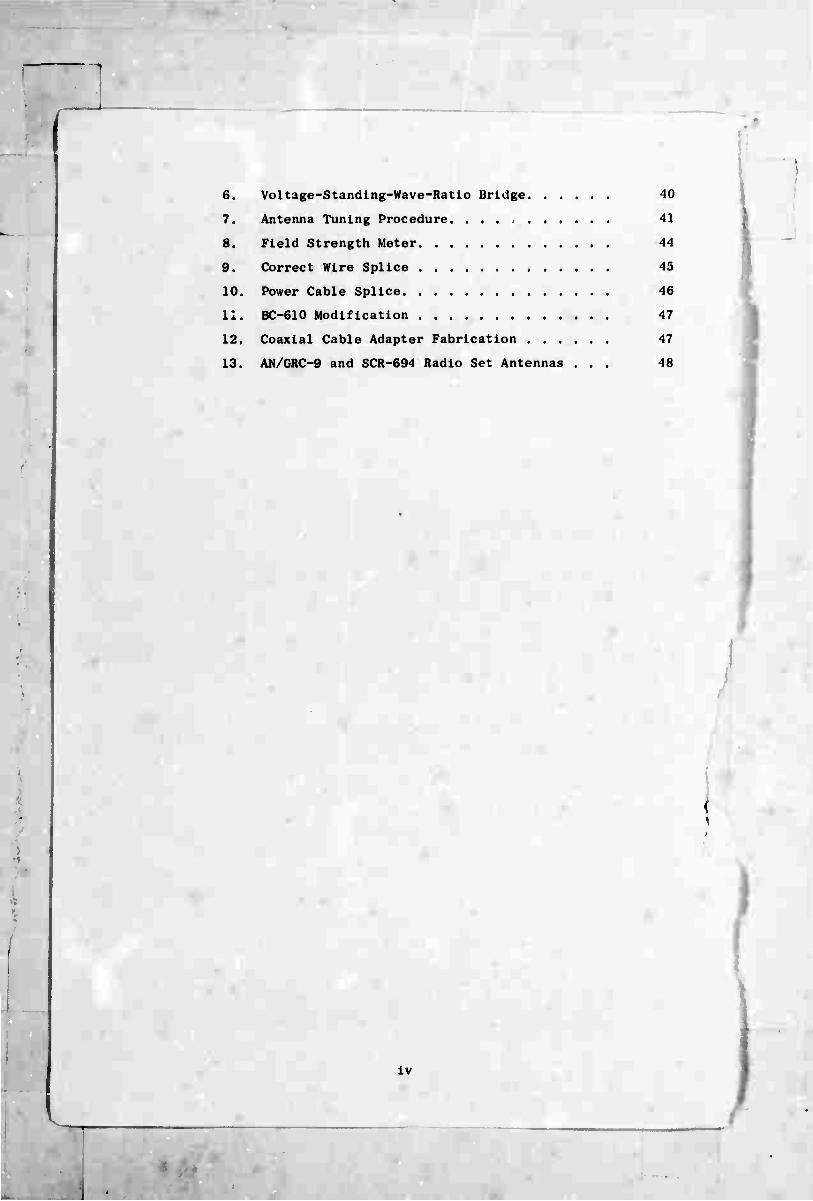
Radio communication is carried on by means of radio waves
traveling from the sending station to the receiving station as shown
In ^Ig. 1. At the sending end, the radio waves are launched into
space by an antenna. At the receiving end, a similar antenna inter-
cepts some of the radio waves and directs them down to the receiver.
4NTENN*
I i
RADIO WAVES
TRANSMITTER
MICROPHONE
SENDING STATION
ANTENNA
RECEIVER
LOUDSPEAKER
RECEIVING STATION
FIG. 1 COMMUNICATION LINK
From this you can see that the antenna performs a very important
service. The antenna is the place where alternating electric
currents, which flow up a coaxial cable, are changed into radio waves
that can travel through space. At the receiving end the antenna does
the reverse: It changes radio waves back into electric currents.
\

One important thing to know about antennas is that the same antenna
can do both of these things; any antenna that can transmit a signal
can also receive one. Therefore, when we talk about the design of
antennas it is customary to talk about the transmitting antenna only,
because it is understood that the receiving antenna can be exactly
the same. In fact, it is general practice to use the same antenna
for both transmitting and receiving by simply switching it back and
forth between a transmitter and a receiver, as shown in Fig. 2. In
this discussion, we talk only about transmitting antennas, with the
understanding that what works for transmitting will work equally well
for receiving.
ANTENNA
TRANSMITTER
IXK—7 RECEIVER
MICROPHONE
LOUDSPEAKER
FIG. 2 SAME ANTENNA USED TO TRANSMIT OR RECEIVE
To be able to install and maintain an antenna, one must have
some understanding of radio waves and the way they behave. Detailed
knowledge of wave propagation is not necessary, but a few basic-
principles must be understood.
\
1 '

\
Almost any kind of antenna will radiate a signal, but the
antenna is not good if it does not radiate enough signal or if it
sends the signal off in the wrong direction. Our purpose here is to
discuss only those features of radio wave transmission that have some
bearing on the installation and maintenance of a high-frequency (HF)
antenna system.
B. Wavelength and Frequency
No one understands exactly what a radio wave is made of, so its
exact nature cannot be clearly explained. The best we can JO is to
compare radio waves with other forms of waves with which we are
familiar and to say "In some ways they are like this," or "In some
ways they are like that," and thus build up a picture of how radio
waves behave.
Radio waves may be compared to waves started on the surface of a
pond (when there is no wind) or to waves traveling along a rope when
one end of it is shaken. The waves get smaller as they radiate out
from the starting point, until at a sufficient distance they are too
small to be detected. When a stone is thrown into a pond, the water
waves radiate in expanding concentric circles; radio waves from an
antenna radiate in expanding concentric spheres. When one wave
follows after another in a long succession of waves (as they normally
do), we have what is called a wave train. When a transmitter is
sending a signal, its antenna is launching into space a wave train in
which the waves are all traveling on straight lines directly away
from the antenna. The ae radio waves pass through most nonconducting
substances such as wood or air, but they are reflected or absorbed
by conducting materials such as metal rods or the earth.
Two important terms are constantly used in reference to a wave
train of radio waves: the wavelength and the frequency. If one can
imagine for the moment that radio waves are like waves on water, then
the wavelength is the distance fiom the top of one wave to the top of
the next, as shown in Fig. 3. Thus the wavelength is the distance
from any point on one wave to a corresponding point on the next wave.
In Fig. 3 look at the distance between Points A and B and between
I

D-6l«3-4
FIG. 3 DIAGRAM OF RADIO WAVE SHOWING ONE WAVELENGTH
Points B and C; these distances also represent 1 wavelength. The
distance from A to C represents 2 wavelengths. Imagine the waves
moving along from the sending station to the receiving station. The
frequency is the number of waves that go by a fixed point in 1
second; in other words, the frequency is the number of waves the
antenna radiates in 1 second. This is exactly the same as the fre-
quency of the transmitter.
All the radio waves in a wave train travel through space at thf
same speed, like cars in a railroad train, so the wavelengths are the
same everywhere. The distance between the cars on a railroad train
does not change as it moves along; the cars are Just as far apart at
the end of a trip as they were at the beginning. The same is true of
a train of radio waves. Once they are launched, they travel at a
constant speed and a constant wavelength. However, if the frequency
of the transmitter is made higher than it was before, the new radio
waves are then closer together. There is a definite relationship be-
tween the frequency and the wavelength of a radio wave, which is ex-
pressed in the following formula:
300
where
w = wavelength in meters
I

• ■m-
r I f rcquL-iicy in MgacyclM per ■•COlld (iMc/s ) .
KxampK-: A t lansmi tter is operating at a Ircquency of 10 Mc/s. What
is (ha wavelfngth of the signal radiating 1rom the antenna? Using
the al)ove formula, we get
300 10
= 30
The wavelength is 30 meters.
Radio waves always travel through space or air at the same
speed, regardless of their frequency. Ordinarily, you will not be
concerned with the velocity of travel of radio waves. Thoy go so
last that you can assume that the signals arrive at the receiver at
the same lime that you are sending them from the transmitter. It is
interesting to note, however, that radio waves travel 300,000
kilometers (km) per second. In spite of this high speed, the dis-
tance between the waves does not change during the trip any more
than the distance between railroad cars changes during their trip.
C. Polari/ation
Radio waves consist of an alternating electric field combined
with an alternating magnetic field. For this reason, radio waves
are sometimes called electro-magnetic waves. Here we will be con-
cerned only with the electric field. If the electric field is alter-
nating in an up and down direction, the field is said to be vertical,
and the waves are said to be vertically polarized. If the electric
field is alternating in a direction parallel to the earth's surface
the field is said to be hori/ontal, and the waves are said to be
horizontally polarized.
If a person fastens one end of a rope to a tree, stretches the
rope out to full length, and then shakes the end up and down, he will
be generating vertically polarized waves. If he shakes the rope
right and left, he will be generating horizontally polarized waves.
Generally speaking, a vertical antenna radiates vertically
polarized radio waves, and a horizontal antenna radiates horizontally
\

(
polarized radio waves, although (as we shall see later) this is not
always the case.
D. Attenuation
Wo have seen that radio waves get smaller in amplitude as they o
travel out from the transmitting antenna. Therefore the farther away
you go from a transmitter, the weaker the signal becomes. This de-
crease in signal stre 4th is caused by the fact that the energy in
the wave has to spread out over larger and larger spheres as the dis-
tance from the source is increased. This loss in signal strength is
known as attenuation. Long paths naturally have more attenuation
than short paths. Signal is also lost in the coaxial cables used to
connect the antenna to the transmitter (or to the receiver), and this
loss is also called attenuation. It occurs because the radio signal
traveling along the cable actually heats up the center conductor and
the dielectric insulation. Cable attenuation is generally not im-
portant at HF frequencies for lengths under 50 meters.
E. Ionosphere
For all practical purposes you can assume that radio waves
travel in straight lines away from the antenna, as shown in Fig. 4(a).
Imagine, for a moment, the earth without an ionosphere. Then a radio
signal could not be sent to a station on the other side of a mountain
or so far away as to be over the curve of the earth. Radio signals
will not pass through the earth, so it would be impossible for the
receiver shown in Fig. 4(a) to pick up a signal from the transmitter.
The transmitting antenna in Fig. 4(a) is radiating signals in all
directions, but none of them would reach the receiving antenna.
Luckily, however, there is a region of ionized gas located high
above the surface of the earth. This region, known as the ionosphere,
reflects HF radio waves as shown in Fig. 4(b). If you examine Fig.
4(b), you will see that, if the transmitting antenna radiates in all
directions, some of the radio waves will happen to hit the ionosphere
at the right place to be reflected down to the receiver. All the
other radio waves which do not hit the receiving antenna are wasted.
.
J

:w—i
•
RECEIVER
SURFACE OF EARTH
(a) WITHOUT IONOSPHERE
^^s^^- IONOSPHERE
RECEIVER
^-TRANSMITTER EARTH D-«m-s
(b) WITH IONOSPHERE
FIG. 4 EFFECT OF IONOSPHERE
Radio waves are reflected by the ionosphere in much the same way that
a beam of light is reflected by a pane of glass. If you shine the
light directly at the glass, most of it will go through; but if you
shine the light at the glass at an angle, it will be reflected. This
is indicated in Fig. 1(1)) by the radio signals above the antenna
penetrating the ionosphere and passing on through it to outer space,
while the radio signals that strike the ionosphere at a grazing angle
are reflected.
The ionosphere is not a single stable reflector—in fact, quite
the contrary. It consists of several layers of ionized gas which are
constantly shifting about in height and in density. The ionosphere
is formed during the day by the sunlight striking the atmosphere.
I

During the night, in the absence of sunlight, the ionosphere tends
to disappear, but it does not disappear altogether. Each day the
ionosphere is formed again by the sunlight. Therefore, high-
frequency signals may fade out at night because they are not re-
flected as well then as they are during the day.
An important factor is that a high-frequency radio wave pene-
trates through the ionosphere more easily than a low-frequency wave
does. A high frequency that can be used for sending a message during
the daytime when the ionosphere is a good reflector may not work at
night when the ionosphere decreases in density, because the radio
waves will then go right through. If the high-frequency radio wave
passes completely through the ionosphere, the message will nut reach
its destination. To prevent this, a lower frequency should be used
at night, because low frequencies reflect better than high fre-
quencies, and some of the ionosphere remains all night. However,
low frequencies cannot be used in the daytime because of another
ionospheric effect. During the daylight hours, a different layer
forms along the bottom of the ionosphere that absorbs low-frequency
signals (below 5 Mc/s) without reflecting them. For this reason,
signals from low-frequency radio stations can be heard better at
night, because they are absorbed by the bottom layer of the iono-
sphere during the day. Therefore, during the daytime the radio
operator must use a frequency high enough to get through this ab-
sorbing layer but low enough to be reflected by the layers above.
To do this, the best policy is to use the highest frequency that will
be reflected back to earth. This is known as the Maximum Usable
Frequency, or MUF. Charts are published showing the MUF predicted
for different times. These charts help the radio operator select
which of his assigned frequencies is likely to work best. The height
and the condition of the ionosphere depend upon sunlight, which
varies with the time of day and with the season of the year. Thus
reflections from the ionosphere cannot be relied on to remain con-
stant for long. The selection of the proper frequency for any given
set of conditions is often a matter of trial and error.
.

-
.
II ANTENNA CHARACTERISTICS
General
The function of an antenna is to send out or to receive radio
waves. As stated previously, an antenna that can do one can do the
other. Thereiore, to simplify the explanation, it is assumed here
that the antenna is used for transmitting, and the description of
its operation is oriented in that direction.
An antenna usually consists of a wire or a metal rod mounted
high above the ground in a clear space. There are many types of
antennas, each designed for a different frequency or a different
purpose. One excellent antenna well suited for sendirg messages at
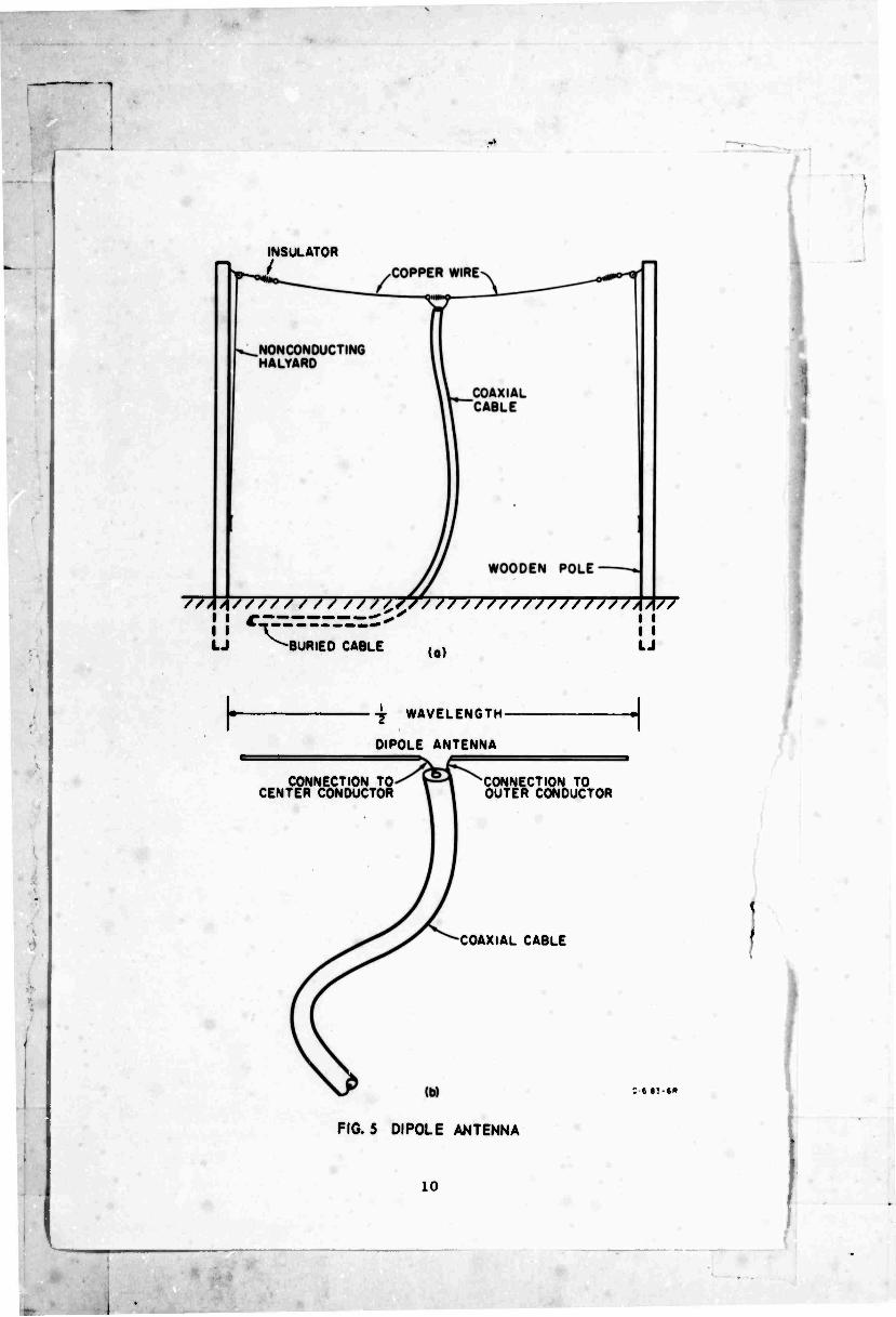
HF frequencies over distances of 0 to 400 km is the dipole. A dipole
antenna is a wire a little less than 1/2 wavelength long, divided in
the center and connected to a coaxial cable, as shown in Fig. 5. The
center conductor of the cable is connected to one half of the dipole
and the outer conductor to the other half. The antenna shown in Fig.
5 is called a haIf-wave dipole.
The most important properties of an antenna are the radiation
pattern, polarization, resonant frequency, and bandwidth. These are
discussed in this chapter.
15. Radiation Pattern
The radiation from an antenna never has equal intensity in all
directions. The intensity may even be zero in some directions, while
in other directions a strong signal is radiated. The best antenna
is one that radiates its strongest signal in the direction you want
it to go—toward the receiver.
The direction toward the receiver is not always a straight line
from the sending station to the receiving station. In fact, quite
the reverse is true: The signal usuallv travels by reflecting off
the ionosphere. When the signal is beiig sent over a 400-km path,
the radio waves leave the antenna at an ingle a above the horizon,
INSULATOR /
//AA////// / / ///CS//////////////////AA//
i i -r- i • ^-»BIIBim rAoi c LJ -BURIED CABLE LJ
h -j WAVELEN6TH-
OIPOLE ANTENNA
CONNECTION TO CENTER CONDUCTOR
CONNECTION TO OUTER CONDUCTOR
COAXIAL CABLE
FIG. 5 DIPOLE ANTENNA
10

PH
as shown in Fi^. 6. (They also arrive at the receiving antenna at
the same angle a.) Radio waves that leave the transmitting antenna
IONOSPHERE
TRANSMITTER \ RECEIVERS >N
V ^/ \^^ o ^
EARTH
400 km-
FIG. 6 HIGH-ANGLE RADIATION
at a steeper angle return to earth at a shorter distance, possibly
at 250 km (as shown in Fig. 6), where there might be another re-
ceiver. Radio waves that leave the antenna going straight up are
reilected straight back down again to their starting point, if their
frequency is low enough. (High-frequency radio waves are more likely
to go through the ionosphere than low-frequency waves, especially if
they hit it at a perpendicular angle.) By looking at Fig. 6 you can
easily see that, if we want to send signals to a receiver less than
400 km away, the radio waves of use to us are going to leave the
antenna at a steep angle. The height of the ionosphere varies
11

"T
between 100 and 300 km; under these conditions, the angle £ will be
between 30 and 90 degrees for sending messages out to 400 km.
The horizontal dipole antenna has been selected as the best
antenna to use under these conditions because it puts out a strong
upward signal, and it radiates a good signal to every point ol the
compass at angles more than 30 degrees above the horizon.
At low take-off angles, the signal radiated is small and is not
equal all the way around, being less off the ends of the dipole. At
zero degrees elevation (a = 0°), practically no signal is radiated
in any direction from a horizontal dipole antenna.
A diagram that shows the strength of the radiation leaving an
antenna in different directions is called an antenna pattern diagram.
Figure 7 is an antenna pattern diagram showing the amount of signal
radiated at a low angle from a horizontal half-wave dipole antenna.
This is a bird's-eye view, looking down on the antenna. Imagine the
antenna located at the center of the diagram, at point 0. The line
XY indicates the direction of the half-wavelength long wire used to
make the antenna, but the length of XY has no significance. The
lines 0A, OB, 0C, OD, 0E, and OF are vectors showing the signal
strength in various directions. The length of a vector represents
the strength of the signal in the direction the vector is pointing.
The longest vector is 0E; this indicates that the maximum signal is
radiated at right angles to the antenna wire. If enough vectors are
drawn to cover all directions from the antenna, it is then possible
to draw a curved line through the points of all the vectors, as shown
by the dashed line in Fig. 7. This dashed line is the antenna
pattern; it is usually drawn as shown in the bottom half of Fig. 7,
without the vectors.
The antenna pattern shown in Fig. 7 is not very useful to you,
because it represents only the radiation from the antenna very close
to the surface of the earth, whereas, as explained previously, the
only radio waves that are likely to reach a receiver a long distance
away are those that leave the transmitting antenna at a high angle
i
12

DIRECTIO ANTENNA
/ /
s ""■"*■. D-6iB3-iea
FIG. 7 RADIATION PATTERN OF HALF-WAVE DIPOLE ANTENNA AT LOW ELEVATION ANGLE
(a in Fig, 6). Therefore, to judge antenna performance, it is more
useful to have an antenna pattern showing the radiation at 30 degrees
or more above the horizon. Figure 8 is a diagram showing the signal
strength (represented by vectors) radiated from a typical half-wave
dipole antenna at 30 degrees above the horizon. As you can see, it
radiates a good signal in all directions. Again, the dashed line
drawn around the cone at the ends of the vectors represents the
actual antenna pattern. To get a better idea of the exact shape of
this pattern, it is customary to plot it on a flat piece of paper as
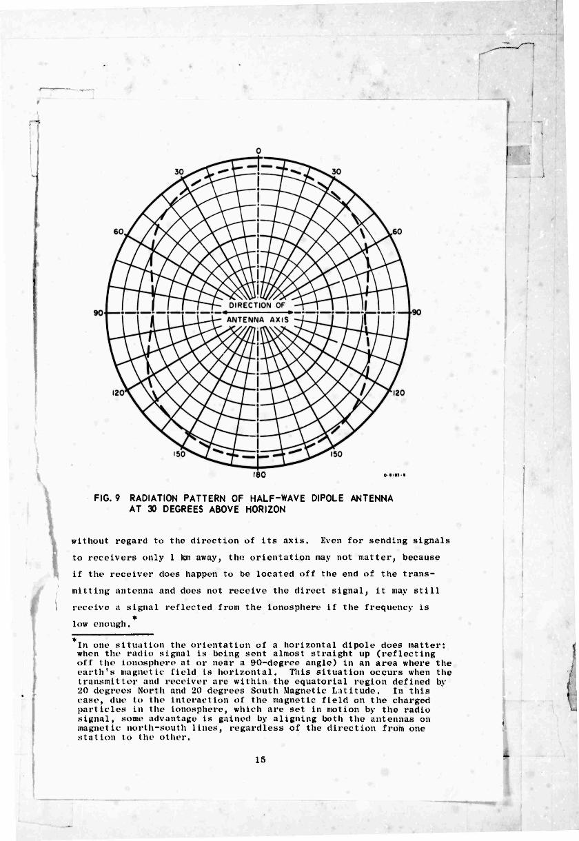
shown in Fig. 9, This is a dashed-line graph in which the distance
of each dash from the center is proportional to the signal strength
in that direction. As you can see, at 30 degrees above the horizon. :
13

[ / , ^ "" "T^ ^"^ ^ '~r' 7 V \\
/ ^ P M/\ya' W
/ A V
o-mj t EAST {/
.
FIG. 8 SIGNAL STRENGTH VECTORS AT 30-DEGREE ELEVATION ANGLE FROM TYPICAL DIPOLE ANTENNA
the strongest signal is radiated off the sides of the antenna wire,
but the signal radiated off the ends is not much less. At take-off
angles above 30 degrees, the dipole antenna pattern changes to a
shape more nearly resembling a circle, so that it has almost equal
radiation in all directions for angles near the zenith.
The patterns shown in Figs. 8 and 9 apply only to horizontal
dipole antennas (1) whose length does not exceed 1/2 wavelength and
(2) mounted less than 1/4 wavelength above the ground. These
patterns do not apply to antennas that are higher than 1/4 wavelength
above the ground. In the example given on page 5, it is shown that
radio waves at a frequency of 10 Mc/s have a wavelength of 30 meters.
Therefore, you can see that in this example 1/4 wavelength would be
7-1/2 meters, and an antenna to be used at 10 Mc/s should be no more
than 7-1/2 meters above the ground, if you want it to have the
pattern shown in Fig, 9,
It is evident from Fig. 9 that it does not make much difference
which way the antenna is aligned when it is put up. For sending sig-
nals over a mountain or over the curve of the earth, the antenna will
work almost equally well in any direction. Therefore, the antenna
can be erected by using the most convenient supports available
I
I
14
1 '
!
180
FIG. 9 RADIATION PATTERN OF HALF-WAVE DIPOLE ANTENNA AT 30 DEGREES ABOVE HORIZON
without regard to the direction of its axis. Even for sending signals
to receivers only 1 km away, tin? orientation may not matter, because
if the receiver does happen to be located off the end of the trans-
mitting antenna and does not receive the direct signal, it may still
receive I signal reflected from the ionosphere if the frequency is
low enough.
In one situation the orientation of a horizontal dipole does matter: when the radio signal is being sent almost straight up (reflecting off the ionosphere at or near a 90-degree angle) in an area where the earth's magnetic field is horizontal. This situation occurs when the transmitter and receiver are within the equatorial region defined by 20 degrees North and 20 degrees South Magnetic Latitude. In this case, due to the interaction of the magnetic field on the charged particles in the ionosphere, which are set in motion by the radio signal, some advantage is gained by aligning both the antennas on magnetic north-south lines, regardless of the direction from one st at ion to the olher.
15
C. Polarization
The radio waves leaving an antenna do not have the same polariza-
tion in all directions. The waves leaving the side of a horizontal
dipole are horizontally polarized. That is, a half-wave dipole
aligned north and soath radiates horizontally polarized signals to
the east and to the west. Also, the same antenna radiate! signals
that are essentially vertically polarized to the north and to the
south, except at zero-degrees elevation, where it radiates nothing.
At intermediats directions above the horizon, it radiates inter-
mediate polarizations. However, this usually does not concern anyone,
for the polarization is further changed by the ionosphere. When the
radio waves hit the ionosphere, they do not actually reflect off the
bottom of it; they penetrate part way through. The higher the fre-
quency, the further they penetrate. Figure 6 shows the radio waves
entering the ionosphere, bending around a curve, and heading back to
earth. While the waves are traveling through the ionosphere and
being forced around the curve (refracted), their polarization is
changed. The waves do not have the same polarization when they leave
the ionosphere that they had when they went in; furthermore, the
polarization angle of the radio waves leaving the Ionosphere changes
from minute to minute as the ionized gas layers shift in position and
density. Therefore, there is no way to predict what the polarization
of the downcoming sky wave will be; it is Just as likely to be ver-
tical as it is to be horizontal, or any intermediate angle. The re-
ceiving antenna can pick up this signal most of the time; however,
since the polarization is changing all the time, there are times when
the antenna cannot pick up the signal. This occurs when the polariza-
tion of the incoming signal is at right angles to the polarization of
the antenna. Luckily, this situation usually lasts only a few
seconds. This is one of the reasons for signal fading, and such
fading will occur regardless of the polarization of the transmitting
or receiving antennas. If a signal fades for this reason, a switch
to another antenna might improve matters, but it would have t be
done extremely quickly.
I 16
D. Resonaiit l'i cqueiicy
A eliixjle antunna (such as the one shown in Fig. 5) opt-rales
properly at only one frequency, the frequency at which it la resonant.
Each dlpole antenna has its own resonant frequency, which depends on
its length. Many other things have resonant (or natural) rrequencies
bealdea antennas. For example, consider a child's swing: A swing
lias a natural frequency, or period. When you are pushing someone in
a swing, you have to push it at the right time in each cycle in order
to keep it going up equally high on each swing. If you push too soon
or too late, you will only cause the swing to slow down. In the same
way, alternating current in a cable that is driving a dipole must
change directions at the same frequency that the current naturally
swings back and forth in the dipole.
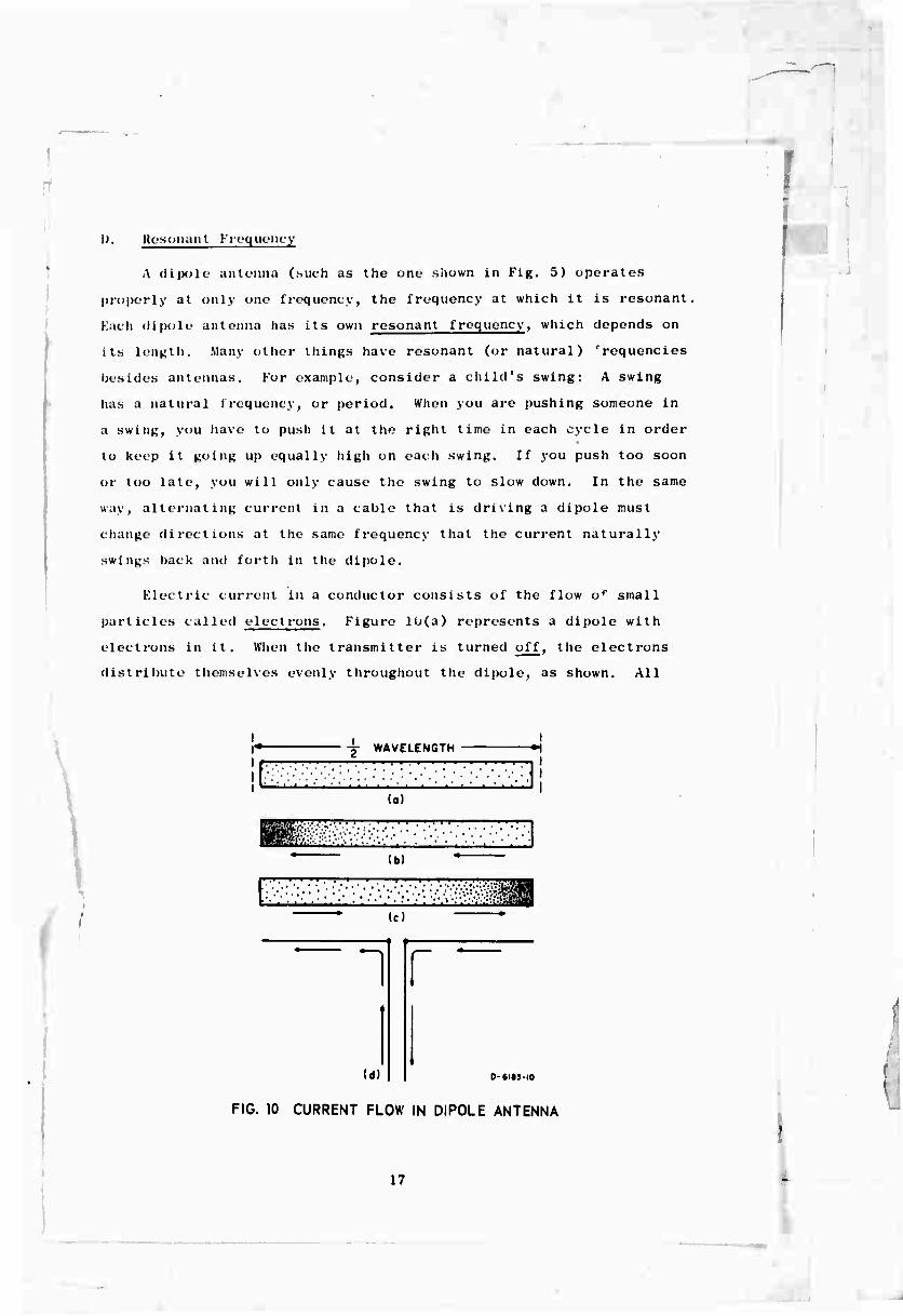
Electric current in a conductor consists of the flow of small
particles called electrons. Figure 10(a) represents a dipole with
electrons in it. When the transmitter is turned off, the electrons
distribute themselves evenly throughout the dipole, as shown. All
I* + WAVELENGTH
,_JMI..l .' I.I I fö'<;:.'v;.v ••.'•. iK-.i'.'.:--: ■■•■■.•;
(a)
lb)
(c)
1
(d)
r im
0-618310
FIG. 10 CURRENT FLOW IN DIPOLE ANTENNA
17

j
electrons repel each other and try to get as far 1rom each other as
possible; that is how they achieve the uniform distribution shown in
Fig. 10(a), When the transmitter is turned on, the electrons (low
back and forth from end to end as shown in Figs 10(b) and (c).
First, the electrons flow to the left and get crowded togethei* in
one end as shown in Fig. ]()(b). Second, since the electrons repel
each other, they push off to the right and get crowded together at
the other end, as in Fig. 10(c). If the signal coming up the coaxial
cable keeps pushing them at the correct time in each cycle, the elec-
trons (which push against each other with an elastic force) will con-
tinue to bounce back and forth from end to end. You can laaglne this
by looking alternately at Figs. 10(b) and (c). The arrows show the
direction of electron flow required to get the electrons into the
position shown. The electrons take a certain length of tine to get
from one end to the other, and the longer the dipole, the longer- the
time is. That is why a long dipole resonates at a lower frequency
than a short one.
The difference between voltage (volts) and current (amperes) in
a dipole is also illustrated by Figs. 10(b) and (c). You can ace
that the maximum flow of current is going to be in the middle of the
dipole. An observer at the center of the dipole would see the elec-
trons rush past, first one way and then the other. The center Is a
maximum current point. Very little current I lows near the ends of
the dipole; in fact, at the extreme ends there is no current at all,
for there is no place for it to go. However, at the ends of the
dipole, there is a great change of voltage; when the electrons are
densely packed, this represents a negative voltage, and when there
is a scarcity of electrons, it represents a positive voltage. Thus
you can see that the voltage at each end swings alternately positive
and negative. An end of a dipole is a maximum voltage point.
The top three diagrams in Fig. 10 show a dipole not connected
to anything. Actually, the dipole antenna must be connected to a
transmission line. The place where this line is attached to the
dipole is called the feed point. The feed point is usually in the
18
I '
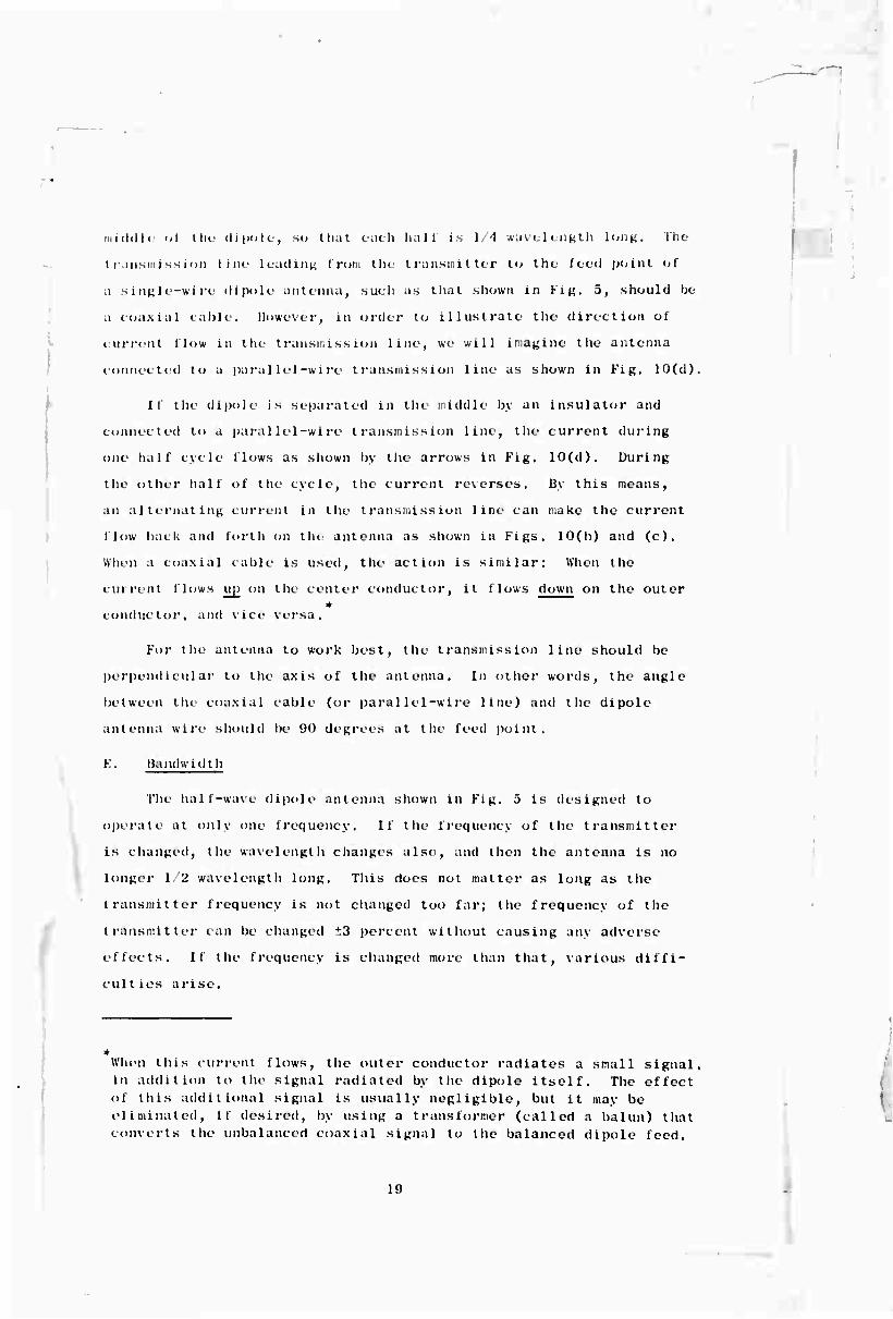
iiiicJcllu öl i ii<- dipolc, so that each hall is 1/4 wavelength long, The
t r.uismi ss mn line leadinn I rom tin transmitter l" the Iced point of
.1 single-wire dipole antenna^ sucli as that shown in Fi^. 5, should bo
,i coaxial cable. However, in order to illustrate the direction ol
current Mow in the transmission line, we will Imagine the antenna
connected to a parallel-wire transmission line as shown in Fin. 10(d),
It the dipole is separated in the middle by an insulator and
connected to a parallel-wire transmission line, the current during
one half cycle 1 lows as shown by the arrows in Fig. 10(d). During
the other half of t lie cycle, the current reverses. By this means,
an alternating current in the transmission line can make the current
flow back and forth on the antenna as shown in Figs. 10(b) and (c).
When a coaxial cable is used, the action is similar: When the
current I lows up on the center conductor, it flows down on the outer
conductor, and vice versa.
For the antenna to work best, the transmission line should be
perpendicular to the axis of the antenna. In other words, the angle
between the coaxial cable (or parallel-wire line) and tile dipole
antenna wire should be 90 degrees at the feed point.
E. Bandwidth
The half-wave dipole antenna shown in Fig. 5 is designed to
operate at only one frequency. If the frequency of the transmitter
is changed, the wavelength changes also, and then the antenna is no
longer 1/2 wavelength long. This does not matter as long as the
transmitter frequency is not changed too far; the frequency of the
transmitter can be changed *:3 percent without causing any adverse
effects. It the frequency is changed more than that, various diffi-
cult los arise.
When this current flows, the outer conductor radiates a small signal, in addition to the signal radiated by the dipole itself. The effect of this additional signal is usually negligible, but it may be eliminated, it desired, by using a transformer (called a balun) that converts the unbalanced coaxial signal to the balanced dipole feed.
19

v
The frequency over which the transmitter can be varied without
the antenna causing trouble is called the bandwidth of the antenna.
The bandwidth of a half-wave dipole of the type shown in Fig. 5 is
±3 percent.
If you send a signal up the coaxial cable that is the wrong fre-
quency for the antenna, the antenna docs not accept all of it. It
sends some of the signal back down the cable again, toward the trans-
mitter. This may be bad for the cable or bad for the transmitter,
and it results in less signal being radiated. If the transmitter is
very powerful and if its frequency is far enough away from the antenna
design frequency, the radio signal coming back from the antenna com-
bined with the signal going out from the transmitter may burn out the
cable or damage the transmitter. When the transmitter is on the wrong
frequency, we say the antenna ref1ects energy back down the coaxial
cable. When the transmitter is on the correct frequency, we say the
antenna matches ^he coaxial cable, and all the energy coming up the
cable is launched into space in the form of radio waves.
As already stated, each antenna has its own resonant frequency
in the same way that a violin string has its resonant frequency.
This resonant frequency depends not only on the length of the antenna
but on its proximity to nearby metal objects or other wires. Some-
times, when the wind blows, the antenna moves closer or farther away
from adjacent conductors, and this changes the resonant frequency
slightly. As long as it is not changed more than the antenna band-
width (±3 percent), very little harm will be done.
If the antenna does not match the coaxial cable lor any reason,
it reflects the radio signal back down the cable. The radio signal
is an alternating current traveling along the cable in the form of a
wave train. The waves going up the cable from the transmitter meet
the waves coming down the cable from the antenna and combine so as
to form stationary waves on the cable. These waves do not move up
or down the cable but remain stationary, or fixed in position like
soldiers marking time. They are oscillating, but they are not getting
anywhere.
20
i "

Those stationary waves, known as standing waves, produce a high
radio-frequency voltage at certain places on the cable and a low
voltage at certain other places. Dividing the voltage at a high
voltage point by the voltage at a low voltage point gives a number
known as the voltage standing wave ratio (VSWR). If there are no
standing waves, the VSWR is equal to 1. As a rule, the VSWR on the
coaxial cable should not lie greater than 2; if it is greater than 2,
you know the antenna is reflecting back too much signal. This will
not happen il the transmitter is kept on the resonant frequency of
the antenna.
It is very important to construct the antenna properly, so that
it will not reflect the signal back down the cable, and it is also
important (when the antenna is used) to keep the transmitter on the
frequency for whuh the antenna was designed. The table following
shows approximately the amount of power lost when the wrong frequency
is used, assuming a constant power output of 100 watts from the
transmitter, and assuming no readjustment of the transmitter output
circult.
I
\
■
Transmit ter Frequency
F (correct frequency) 0.9BF or 1.OIF 0.96F or 1,02F
0.9'1F or 1.01F 0.92F or 1.05F 0.K9F or 1 .06F
0.87F or 1 .07F 0.K5F or 1.09F 0.K3F or 1.10F
0.81F or 1,1 IF
Power Reflected Powei • Radiated from Dipole bv Dipole
(watts) VSWR
1 :!
(« liXiis)
0 100 11 2: 1 89 20 3:1 75
36 4:1 61 •11 5:1 56 51 6:1 •19
56 7:1 •11 60 8:1 •10 61 9:1 36
67 10:1 33 77 15:1 23 «2 20:1 18
The dipole will radiate more power than shown in the last column of
the table (but not the full 100 watts) if the operator takes the
trouble to adjust the transmitter output matching circuit for maximum
21

•
power output each time he changes frequency. However, many trans-
mitters do not have the capability of matching into a VSWR of more
than 3:1, and thus cannot be adjusted to operate efficiently into a
badly mismatched load.
You can think of the antenna as a tuned circuit. When the fre-
quency of the transmitter is below the resonant frequency of the
antenna, the antenna appears to be capacitat ive, as in Fig. 11(a).
If the frequency is slightly too high, the antenna appears to be
i
TRANSMITTER
3 FREQUENCY TOO LOW
(o)
m FREQUENCY TOO HIGH u (b)
FREQUENCY CORRECT
u (c)
ANTENNA
P-1
P-1
9-1
FIG. 11 EQUIVALENT CIRCUITS FOR ANTENNA BELOW, ABOVE, AND AT RESONANCE
inductive, as in Fig. 11(b). When the transmitter is adjusted
exactly to the resonant frequency of the antenna (or vice versa) the
antenna appears to be a resistor, as in Fig. 11(c). In the latter
case, no signal is reflected back from the antenna, and the VSWR is
1; all the power from the transmitter goes into the antenna. Since
there is not a real resistor out at the antenna, there is nothing
out there to get hot and use up energy; all the power going into the
22
I "

^w—1
■
antenna is therefore radiated. The laaginary resistor shown in Fig.
11(c) is called the radiation resistance of the antenna. For best
results, this radiation resistance should be the same as the
characters tic impedance of the coaxial cable being used, The
radiation resistance of the antenna depends on its height above the
ground and on the location of the feed point, that is, on whether
the coaxial cable is connected in the middle or not. The value of
R in Fig. 11(c) can be raised either by putting the antenna up higher
above the ground or by moving the feed point away from the center.
11 the feed point is in the center and the antenna is very high above
the ground, the value of R will be about 70 ohms.
Another way to increase the value of R is to use a folded
dipo1e, as shown in Fig. 12, A folded dipole is just like a half-
wave dipole (Fig. 5) except that one parallel wire is located about
L WAVELENGTH
LADDER LINE
INSULATED SPACER.
0-«l«3-l2«
FIG. 12 FOLDED DIPOLE
Each type of coaxial cable is designed to go with a particular value of resistance; RG-H/U should be terminated in 52 ohms.
■
I 23

1 ■
15 centimeters (cm) from the original antenna wire. This new wire is
connected at each end to the ends of the half-wave dipole. When this
is done, the value of R goes up to four times what it was before.
The VSWR on the transmitting cable depends on what is connected
at the antenna end. To avoid standing waves, you must meet two re-
quirements: (1) The antenna must "look" like a pure resistance, as
in Fig. 11(c), and (2) the value of this resistance must bo equal to
the characteristic impedance of the cable being used.
It has been mentioned that a half-wave dipole antenna is actually
not 1/2 wavelength long. It turns out that when the length of the
antenna is adjusted so that no reflections occur—and there are no
standing waves on the cable—the antenna is about 5 percent less than
1/2 wavelength long. Another way of saying this is that the antennas
in Figs. 5 and 12 should be cut to an overall length of approximately
95 percent of 1/2 wavelength. This is expressed in a formula as
follows:
95 w IOC 2
where
L = correct overall length for a half-wave dipole antenna
w = operating wavelength.
Example; What should be the overall length of a half-wave dipole
antenna designed for operation at 6 Mc/s?
Step 1: Change 6 Mc/s to wavelength.
Wavelength = —r-, (from page 4) b
Wavelength = 50 meters.
Step 2: Find 95 percent of 1/2 wavelength.
_ 95_ x 50 4750 " 100 2 = 200
L = 23.75 meters.
24

f
-n
Answer: A 6-Mc/s half-wave dipole should be 23.75 meters long. (Each half would be 11.875 meters long.)
Figure 13 is a graph from which you can determine the approxi-
mate overall length to make a half-wave dipole antenna to work at
various frequencies. You remember that it has been stated that the
length of the antenna should he approximately 95 percent of 1/2 wave-
length. It is impossible to give un exact formula for the length of
a dipole antenna because that depends on the proximity of other wires
and conducting materials. Therefore, if a method of measuring the
VSWR is available, it should be used; the Appendix gives a method for
doing this.
I 25

70
60
50
40
-: 6 30
UJ 20
10
i ^ m i ■i i: : • ; • j . : . ..,:.- • ■
1 1
__..J
■
^ ! :
■j :m ■ :.: 1
■ 1 . : t
; : l MT i • 4 i - • i i i ■ ■ : - -i
■:i!: ;-
.. . i ■ • i ■ : ^nN. . ; ■
....... •f 1 11
:■: h „..;..-. ^L ^W j WAVELENGTH
^^ ■ \ Ofi ..,
.1 i . 1 * L.
. ■ ,.
^ i ■
\ • ■ •
• ■ 1 ' ... I
... |. .......
1
■
■
• i• •*• - ■ • •
i * ■ ■i • ; j;: ... • -t ....
.. . ■. -44-... ^ ' 1
-H ■ hi T ■ - nT|4r—:~- ^Kr^u ' * . .—*-. — ..
—1— . r. 1-. . :i:r 4 — ——4— i
- j gp: r Jjt ['■'■- IH ■ tii — \ V
" ""t": ,
1 — t • * • ^3rZ.i'.t ,'\ ','. -___;_ i
t i ( XT ^Ttit Lil' ' I)*1
- -T~ r^|
i ' !■ ■'■■!■ ■ * ■ i vsT • ....
11TT T r i ' UAI C_u/A\<c iMDrti rr Xv ....
!• -t ■ ^ — —. ^^
. .... •t-T — (9! 5% OF T WAVELENGTH) ^ I 4 | . ■
i . 1 • i - .( . , t ■ ■ ■ i
BE ,,l ,
1
1 \
, jrr: .. _:.!■ ' 'L.' 1 i -■j t ■ ■ r j ■ •: • * » » ■
• i :
:..
■
rtji . .! . . . , ———
t . ..
i
.,. . , • ' ; i ^ . ..i i
4 5 6 FREQUENCY Mc/s
8 9 10 0-6183-13
FIG. 13 LENGTH OF HALF-WAVE DIPOLE ANTENNA
26
T"

Ill MULTIBAND ANTENNA
A. LK-scrlptioii
A .sending station is assigned certain frequencies and is nor-
mally not allowed to use any others. If separate dipole antennas
are used, each one works at only one frequency. The station operator
selects the best frequency for the time of day and for the distance
to the receiver, and he also selects the correct dipole antenna to go
with that frequency. Whenever the operator changes frequencies, he
must change antennas as well.
However, some of this antenna switching can be avoided by
mounting three dipole antennas together as shown in Fig. 14. All
three antennas are connected to the same coaxial cable all the time,
which allows the operator to transmit on any one of the three fre-
quencies without changing the cable connections. This is the way it
works: The three dipoles are cut to three frequencies that will be
used at that station. When the transmitter sends a radio signal up
the cable, the antenna designed for that frequency resonates, but the
other two antennas reject the signal. Thus most of the current flows
in the resonant antenna, and very little signal is reflected back
down the coaxial line. The antenna that has the current flowing in
it radiates radio waves in the normal manner, while the other two
antennas do nothing. If the transmitter sends up a frequency that
is not one of the three design frequencies, none of the antennas
resonates properly, and there is a reflection of radio signal back
down the cable that causes standing waves in the cable.
This type of antenna is called a multiband antenna because it
will work at more than one frequency. Since it will actually work
over bands of t2 percent on each side of the three design frequencies,
it is called a multiband antenna rather than a mult ifrequency antenna.
27

< z
I- z < Q z < CD
3 as
o
28
.
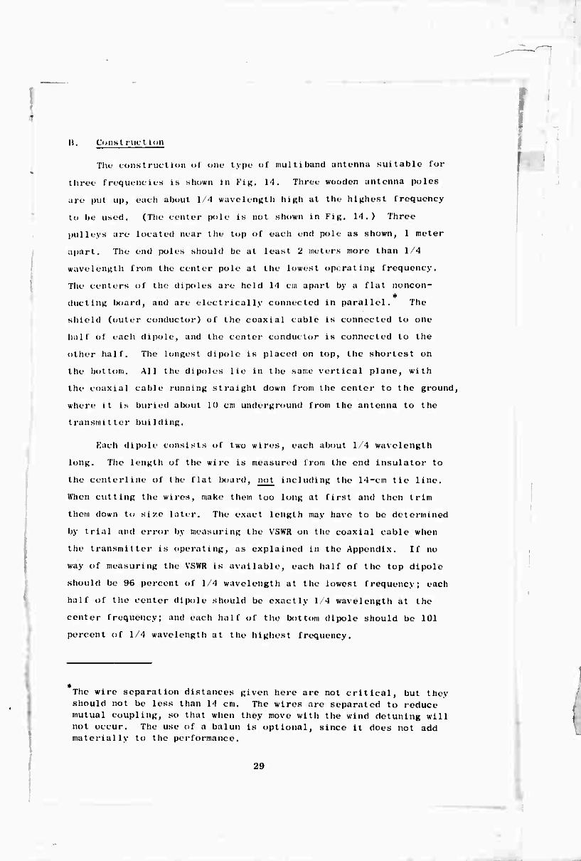
li. Const ruetion
The construction ol one type- ol mullibaiul antenna suitable for
three frequencies is shown In Fi^. 14. Three wooden antenna poles
are put up, each about 1/4 wavelength high at the highest frequency
to be used. (The center pole is not shown in Fig. 14.) Three
pulleys are located near the lop of each end pole as shown, 1 meter
apart. The end poles should be at least 2 meters more than 1/4
wavelength fron the center pole at the lowest operating frequency.
The centers of the dipoles are held 14 cm apart by a flat noncon-
ducting board, and are electrically connected in parallel. The
shield (outer conductor) of the coaxial cable is connected to one
half of each dipole, and the center conductor is connected to the
other half. The longest dipole is placed on top, the shortest on
the bottom. All the dipoles lie in the same vertical plane, with
the coaxial cable running straight down from the center lo the ground,
where it is buried alxuit 10 cm underground from the antenna to the
transmitter building.
Fach dipole consists of two wires, each about 1/4 wavelength
long. The length ol the wire is measured from the end insulator to
the centerline ol the flat board, not including the 14-cm tie line.
When cutting the wires, make them too long at first and then trim
them down to size later. The exact length may have to be determined
by trial and error by measuring the V3WR on the coaxial cable when
the transmitter is operating, as explained in the Appendix. If no
way of measuring the VSWR is available, each half of the top dipole
should be 96 percent of 1/4 wavelength at the lowest frequency; each
half of the center dipole should be exactly 1 4 wavelength at the
center frequency; and each half of the bottom dipole should be 101
percent of 1/4 wavelength at the highest frequency.
1
The wire separation distances given here are not critical, but they should not be less than 14 cm. The wires arc separated to reduce mutual coupling, so that when they move with the wind detuning will not occur. The use of a balun is optional, since it does not add materially to t lie performance.
29

Konconduc t i ng rope must be used bftwet'ii t he insulators and tht»
polos; if this section is made of wire, it will detune the antenna.
The ropes must be kept at the right tension so that the spacing be-
tween the wires does not change from day to day. To radiate a ätrong
signal, it is necessary to keep the antenna from sagging and to keep
the transmitter exactly on one of the three antenna frequencies.
C. Pattern
Each part of the multiband antenna is simply a half-wave dipole,
so when it is operating on one of its three resonant frequencies, it
has the pattern shown in Fig. 9.
M)

.
IV SINGLK-WIRK ANTENNA
A. Description
The simplest type <>i antenna is a wire strung up on poles Above
the ground, with one end connected to a transmitter. In some siiua-
tlons. this type ol antenna is quite satisfactory. It can be used
to advantaRe with transmlttlng-recelvlng equipment like the SCR-
694 (or the .AN GRC-9) which lias one terminal marked ANTENNA and
another marked GROUND. The length ol the signal wire plus the down
lead is made slightly less than one-half wavelength. On a half-wave
antenna there is a point of maximum current flow in the center and
points ol maximum voltage at each end. The radio signal from the
transmitter should be fed Into the antenna at the end. When the sig-
nal is fed Into the middle of an antenna, as shown in Fig. 10, we
have what is called current leed, and the radiation resistance appears
to be about 50 ohms. When the signal is fed Into the end of an
antenna, we have what is called voltage leed, and the radiation re-
sistance appears to be very high, perhaps 2000 ohms. In on«, ca ,
the cable supplies high currents to the antenna at the point of
current maximum; in the other case, the transmitter supplies high
voltage to the antenna at the point of voltage maximum. In either
case, the result is the same--the electrons flow back and forth as
shown in Kigs. 10(b) and (c).
li. Const met ion
A transmitter designed to operate into a voltage maximum point
on the antenna should be connected as shown in Fig. 15. As far as
the electrons are concerned, the down lead and the antenna are all
one long piece of wire, and they will resonate therein at a frequency
depending on the total length. The total length should be 95 percent
of 12 wavelength. The antenna will work properly on only one fre-
quency. 11 the Frequency of the transmitter is changed, the length
of the antenna must be adjusted accordingly. If this is not done,
the full power of the transmitter will not be radiated.
1-. —•
•
31
1
ANTENNA
DOWN LEAD-
TRANSMITTER
1
"X 95% OF i WAVELENGTH
)
^—GROUND CONNECTION O 6185 >4R
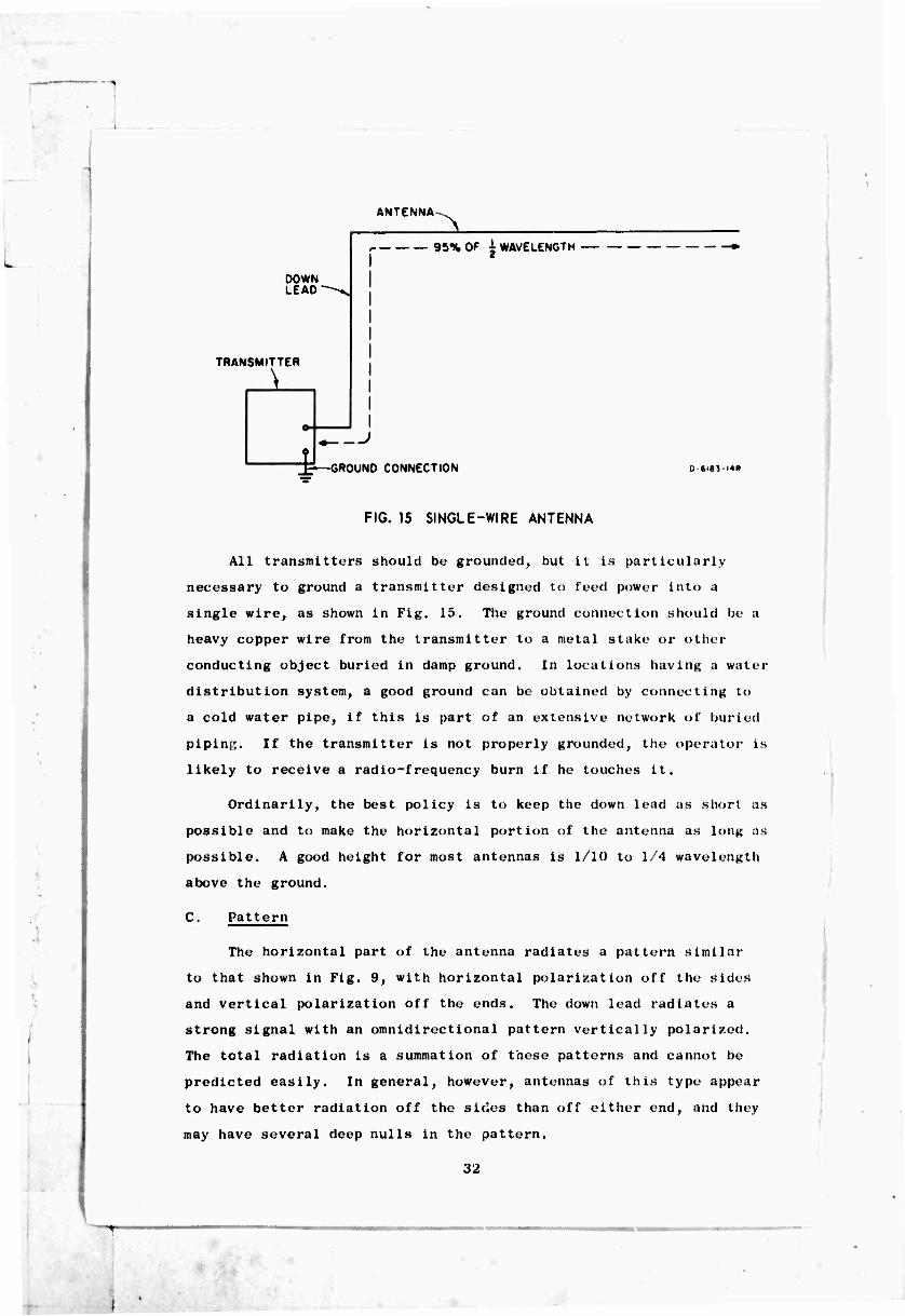
FIG. 15 SINGLE-WIRE ANTENNA
All transmitters should be grounded, but it is particularly
necessary to ground a transmitter designed to feed power into a
single wire, as shown in Fig. 15. The ground connection should be a
heavy copper wire from the transmitter to a metal stake or other
conducting object buried in damp ground. In locations having a water
distribution system, a good ground can be obtained by connecting to
a cold water pipe, if this is part of an extensive network of buried
pipin,;. If the transmitter is not properly grounded, the operator is
likely to receive a radio-frequency burn if he touches it.
Ordinarily, the best policy is to keep the down lead as short as
possible and to make the horizontal portion of the antenna as long as
possible. A good height for most antennas is 1/10 to 1/4 wavelength
above the ground.
C. Pattern
The horizontal part of the antenna radiates a pattern similar
to that shown in Fig. 9, with horizontal polarization off the sides
and vertical polarization off the ends. The down lead radiates a
strong signal with an omnidirectional pattern vertically polarized.
The total radiation is a summation of tnese patterns and cannot be
predicted easily. In general, however, antennas of this type appear
to have better radiation off the sides than off either end, and they
may have several deep nulls in the pattern.
32

I lor communication hit w<«ii (ixifi K''"'""' stations, where the
diroctioti fron one station to the other (iocs not chann'-, a salis-
factory orientation ol the antenna can be found hy trial and error.
The horizontal part does not have to he exactly horizontal, nor does
the down lead have to he vertical, hut for optimum power output the
total length must he 95 percent of 1/2 wavelength.
.
33

BLANK PAGE
i

Appendix
INSTALLATION AND OPERATION OF ANTENNAS AND EQUIPMENT
This Appendix gives specific instructions for field radio main-
tenance and operating personnel. These instructions are based on
situations encountered at Communications Centers and typical outpost
stations by ■ field survey team.
]. Pole Local ions
The transmitting antennas will be multi-element dipoles as shown
in Fig. 14. Most of the antennas will have three elements, each tied
at the center to a common feed point, giving the appearance of a fan.
All the receiving antennas will b .■ single-element dipoles cut
for operation at 9.5 Mc/s. This makes chem 15 meters long.
At eich location the antennas will require three poles for the
transmitting antenna and one for the receiving antenna, as shown In
Fig. A-l. The transmitting antenna will be located so that the
center pole is fairly close to the radio room. The poles should be
BUILDING
O—■
p-j^- RADIO ROOM
J-J ^TRANSMIT ..^ / 0
WALL >
-RECEIVE
FIG. A-l EXAMPLE OF ANTENNA POLE SITING
10 meters long, or longer,«with 15 percent of this placed in the
ground; spacing between poles must be at least 2 meters more than
l/A wavelength at the lowest operating frequency. Attached to the
top of each end pole will be three pulleys for the antenna halyards.
The center pole will have one pulley for supporting the center of
i
35

Rope Length Frequency (meters)
Low 22
Medium 21
High 35
— 20
20
the transmitting antenna and another pulley for the end of the- re-
ceiving antenna if it is attached there. If it is more convenient^
the receiving antenna can be attached to one of the end poles and run
perpendicular to the transmitting antenna.
The pulleys should be attached and the ropes strung through them
before the poles are erected. The top pulleys are located 1/4 meter
from the top, and the lower pulleys are spaced 1 meter apart. The
minimum lengths for ropes on one pole are:
Location
End pole, top pulley
End pole, center pulley
End pole, bottom pulley
Center pole, each pulley
Receiving antenna pole
When the poles are set, and before the holes are filled, the poles
must be rotated so the end-pole pulleys face inward. The center-pole
pulleys face to the side.
2. Hanging the Multiband Antenna
Tie the rope from the center pole to the insulating board at
the center of the transmitting antenna. Hoist the center of the
antenna first, on the center pole, being careful to keep the antenna
wires from tangling, and letting out coaxial cable at the same time.
When the antenna has been hoisted, secure the rope to a spike near
the base of the pole. Taking the halyard.«- from the tops of each end
pole, tie them to the longest (lowest frequency) antenna wire insu-
lators; hoist the wire with even tension in both directions; and
secure the halyards to the spikes at the base of the poles. Next,
using the center pulleys, hoist the medium-length or center antenna,
being careful to keep even tension in both directions. Finally, into
the lowest or bottom position, hoist the shortest, or highest-
frequency antenna wire. If necessary, readjust the tension of the
ropes so as to make the wires equally spaced.
36

Now run KG-KA/U coaxial cable from the center pole to the
building. Either bury it in a stone trough or hang it with a
supporting cable between the pole and the building at a height of 3
meters or more. Supporting cable will not be required if the dis-
tance from the pole to the building is 5 meters or less.
Bring the cable inside to the transmitter; cut it to length; and
attach a PL-259 coaxial connector to the cable, in accordance with
the assembly instructions provided. The coaxial cable between the
antenna feed point and the transmitter should be continuous and un-
broken, with no splices.
3. Receiving Antenna
The method of putting up the receiving antenna is the same as
that for the transmitting antenna except:
(1) Type RG-58C/U coaxial cable can be used instead of RG-8A/U.
(2) The antenna will be a single wire (see Fig. 5) with each side cut to 7-1/2 meters, instead of the multi- wire configuration of the transmitting antenna.
Placement of the antenna is as follows: One of the transmitter
poles is used for one end of the receiving antenna. The axis of the
receiving antenna is 90 degrees (perpendicular) to that of the trans-
mitting antenna. The coaxial feed line goes straight down to the
ground and then into the building.
4. Grounding Equipment
Everybody must understand the importance of grounding the radio
equipment. This is a necessity to protect the lives of the operator
and the maintenance personnel. Ground is at zero potential (no vol-
tage), and ungrounded equipment is usually at some ac potential above
ground. Your body can conduct electricity. If you make a connection
with your body between a piece of ungrounded equipment and the ground,
electricity may flow through you. When you touch the equipment
(especially if you are standing on a damp or wet floor) you will
often be able to feel in your body the difference of potential
.
37

1
(voltage) between the equipment and the ground. It you happen to
make a good connection a high current may flow, possibly enough to
kill you. However, if the equipment is already connected to ground
with a good conductor, there will be no potential difference and no
current will pass through you. It will go tin >ugh the ground con-
nection instead.
Not only the transmitter at each station must be grounded but
also the radio receiver, control unit, transformer, and metal table
must be grounded to a common point. This common point should be a
metal rod not less than 1-1/2 meters long driven into the ground
through the floor, if possible. Part of the rod should be left ex-
tending above the floor for connection of ground wires of future-
equipment. The wire length from any piece of equipment to the ground
rod should not exceed 2 meters. The ground wire should be heavy
gauge and soldered if it has been spliced. Individual wires, each
with its own ground clamp, should be used from each equipment to the
ground rod. Do not connect the equipment in series along the ground
line. This can cause excess hum in the transmitter modulation and
on the receiver. Grounding should be connected to the main frame of
the transmitter (not to a rubber shock mount, which seems to be
commonly used).
5. Safety
In a few instances, some of the safety interlock switches at
transmitting stations have been "jumpered" (electrically bypassed)
at access doors to the BC-610 tuning units and power amplifier tank
coils. This is dangerous practice because it removes a safety
feature that was built into the transmitter to protect the life of
the operator. For example, when the operator is changing a tank
coil, he turns the plate power switch off, opens the door and,
assuming the plate power is off, reaches in to change the coil.
When working with high voltages such as in the BC-610, there should
be no assumptions. One must be sure, because his life depends on it.
If the interlock switch has been jumpered and if the plate power
switch happens to be short-circuited, thus keeping the power on even
38

I
aller the switch has bvvn turned off, the operator may come into con-
tact with 2500 volts dc, and he may be killed. He is also liekly to
be killed, ol course, if he forgets to turn off the plate power
swi tch.
It is also possible to be electrocuted when all the interlocks
are working properly, with all the power turned off. For example,
take the case where the bleeder resistor of the high-voltage power
supply is open or burnt out. Normally, when the operator turns the
plate power switch off, he removes power from the plate transformer
and the liigh-voltage rectifiers. The high-voltage filter capacitors
discharge through the bleeder resistor in a short time. When this
happens, it is sale to reach in and touch the coil after the power
is turned off. However, if the bleeder resistor is broken, there is
no discharge path to the ground, and the high-voltage filter capaci-
tors remain charged to a high voltage, +2500 volts in this case, for
an indefinite length of time after the power has been turned off.
The charge on these capacitors can kill you just as fast as when the
power is turned on.
Each transmitting station is equipped with a grounding stick,
or if not, each should have one. This stick, made of nonconducting
material, is equipped with a metal cap attached to a length of
grounding wire. The end of this grounding wire should be permanently
connected to the transmitter main frame. Do not use a clip for this
connection, because it might come loose. A permanent attachment
assures you of a good ground connection and at the same time keeps
the stick from straying from the transmitter.
Each time the access door to the power amplifier tank coil is
opened, and before the operator reaches in to change the coil, the
stick should be used to ground the plates of the power amplifier
tuning capacitor. This assures you that no voltage will be left on
any component when you reach in.
39

6. Voltage-Standing-Wave-Ratio Bridge
This is a handy, compact device for checking the transmitter
operation at a radio transmitting station. For VSWR measurements,
it uses the bridge method of comparing the power supplied _t_n the
antenna with that reflected from the antenna. The operation is
simple, and accurate matching >! the antenna to the transmitter can
be done quickly. The VSWR bridge is used at sites where a coaxial
cable connects the transmitter to a dipole. It cannot be used with
a long-wire antenna. The procedure is as follows:
(1) Turn the transmitter off. Disconnect the antenna coaxial cable at the transmitter output.
(2) Connect the bridge INPUT connector to the trans- r itter output and the ANTENNA connector to the '„able. A short cable equipped with male connectors on both ends will be required between the trans- mitter and bridge.
(3) Set the switch to the FORWARD position, and rotate the adjusting knob to near minimum position (counter-clockwise).
(4) Turn the transmitter on, and rotate the adjusting knob for full meter swing.
(3) Set the switch to the REFLECTED position. Read the VSWR from the meter scale.
*
A perfect match (1:1 ratio) is ideal and is theoretically
possible. Adjustments on the transmitter and antenna should be made
so that the VSWR is as low as possible. A VSWR of 2:1 is considered
satisfactory; one of 3:1 is acceptable. Anything greater than 3:1
is not acceptable and can result in damage to the transmitter.
The VSWR bridge can also be used for another purpose: to monitor
the transmitter output power continuously. To do this, set the switch
to the FORWARD position and adjust the knob for a meter swing to about
midscale with the transmitter "on." Abnormal variations of the trans-
mitting system will then be indicated by the meter. The instrument
consumes practically no power when used in this manne:-.
40
\

7. Antc-niKi ruiiii]^ I'locidurc
The nethud <>1 antenna adjustment described here requires the
us» <>! an indicator like the one described in Sec. 6 above to show
tin VSWR in the cable leading trim the transmitter to the antenna.
This method can be used for both the hall-wave dipole and the multi-
band antenna.
All the wires ol a multiband antenna affect each other, but the
top win- is the most independent of the three. Therefore, when you
adjust a multiband antenna, adjust the top dipole first, then the
second, and then the Ijottom one. Repeat the adjustment again if
necessary| in the same sequence.
It is not necessary to put the antenna up and down a great many
times, each time clipping it a little bit shorter until you get it
right. On the contrary, t lie proper way to adjust a single-dipole
antenna is to put it up once and measure the VSWR; take it down,
adjust it to the right length, and put it up a second time for a VSWR
check; take it down, cut off excess wire, and put it up for the third
and last time. This is accomplished in the following steps:
(1 ) Put up the aiiteima for a Irequeiicy check.
Put the feed point in the center, so that eacli half will be equal, Determine the assigned station fre- quency, and make each half about 14 wavelength long. Make the wires slightly too long, so they can be cut shorter later. To be too long, the wires for a single dipole and for the top element of a multiband antenna should be 1,1 wavelength, and the wires lor the center and bottom elements of t lie multiband antenna should be about 20 cm longer than 1 •! wavelength.
(2) Calculate the amount to cut off.
Measure the VSWR in the cable, and adjust the fre- quency of the transmitter for minimum VSWR. This should turn out to be lower than the utation fre- quency if you have made the trial uitenna correctly. Measure the Frequency of the transmitter when it is adjusted so as to give the lowest VSWR obtainable. This will be the resonant frequency of the antenna you i.ave made; we will call this the measured frequency. The amount of wire to cut off is found from t he I o 1 lowi i •':
11
-

>
Riilt—To increase the resonant frequency of a Hpole by a snail percentt shorten its length
by the sane percentt anil vice versa.
In other words, il the measured frequency of your dipole is 3 percent below the station frequency, the dipole is too long, and its IciiKth should be de- creased by 3 percent.
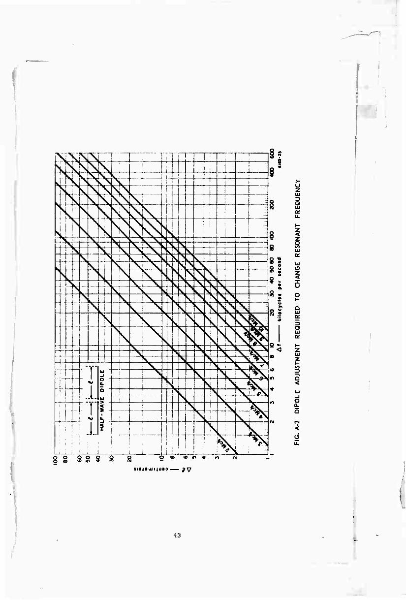
Another way to find the amount to cut off is to use the graph in Fig. A-2. This graph shows how much to remove from each half of a dipole to make the resonant frequency rise by a small amount. The frequency change is called delta f (&l) and is plotted along the bottom of the graph. The amount to cut off to make the frequency rise is called delta I (AX) and is plotted vertically. The first step in using this graph is to draw a straight diagonal line representing your station frequency between the lines shown on the graph. The location of this line may be estimated visually. Use this station-frequency line when adjusting an antenrj for ^hat frequency.
If the resonant frequency of the antenna is too high, by an amount Af, each half of the antenna must be lengthened by an amount Ai as read from the graph. If the resonant frequency is too low, each half must be shortened.
(3) Shorten the antenna.
Do not cut off the extra wire at first. Make each half of the dipole shorter by folding the wire back on itself, with the extra piece wrapped loosely around the main part. This allows you to make it longer again in case you go too far. This is im- portant when adjusting the multiband antenna, be- cause an adjustment of one dipole may detune the next one.
(4) Make the final VSWR check.
Pull the antenna up into position, and tune the transmitter for the frequency that gives the lowest VSWR. This should be equal to the station fre- quency. If it is, lower the antenna, cut off excess wire, and make tight wire-wrap connection at the insulator. If the frequency for the minimum VSWR does not come out on the assigned station frequency, go back to Step (2).
The VSWR should be 2:1 or less when the transmitter is tuned for minimum VSWR. If It is not possible to get the VSWR as low as 2:1, it is because the
42
'--
xx \ LN r- j | i 1
i L
;
VkN s Nj t i I •XIX^ \ s V~ i i i 1 i
1 ' s s
> I ! 1 I i 1 i i
s i 1 ! i I "
J j
< XX ' | X. X. ^.
X. T» Xj
i
l r^. i , «s. ^ >. ; ; i . 1 HL ^ k >L ^v:^^ ^L r^ ,. \ ! 1 '
4t> L i
^s \ \ •k. ^*L.i ^ ^J i \ k X "V ^ Sv 1 i i X X ^v ^^ i ^s CN V o k' : | s >
V N >
s s ̂ 1
1 i \. ; _. X j
^ s ^
V Si Ov
1 s L, \ ; ^fc^ p
K \ X s ̂
$
.
N k ; \ ! >l \
1
1 >
^ i
>
\ kN
^fe I I
1
L IN i X 1 X
^ _i i_ J
, ^ V v >
. »v ^y -* -4-
1 l l
i V > k ' X V «x i
i s V L X X v^\J 4t ....,, ,—,
4- Ui
o " & o -
< »
; \ \ 1 v. fev^ ! X 1 ! V \ \ *X i ! > V N k^v ... i ■ n n rs XrX ,
i k V x 1 i s . i
\ X LU i 1 i
I \ i > \ ^\
■ | 1
1 ! ; ._ ■
i 1
i; ii
L ' 1T \ k N ^
§■■ 8
>- u 2 HI -)
! O UJ a: u. (-
8 I z 8
a
!1 HI
8S O
a 5 s . o • t-
u
81 Q LU
9 3 O UJ o:
S - I- < z
CD HI 2 y- UO • 3 —>
«■> Q <
«• LU _J o a. a
CM CN
< Ü
ö « * *) * m O o « i« m *
Si*i»aii|u*3 — /y
43

radiation resistance--R in Fijj. ll(t') — is not equal to the characteristic impedance of the trans- mission line. Raising or lowering the dipole will change the radiation resistance and may decrease the VSWR. When a half-wave dipole is 1/5 wavelength above the ground, its radiation resistance is about 52 ohms, which is the correct value to use with RG-8/U cable. A folded dipole (Fig. 12) has a re- sistance four times as high as a single dipole and should not be used with RG-8/U cable.
8. Field Strength Meter
One method for tuning the AN/GRC-9 is to use a field strength
meter, which can be constructed with very few parts. The principle
by which it operates is simple. The field strength unit is placed
near the transmitting antenna, or near the down lead, where it can
pick up some of the energy being radiated. The amount that it picks
up is indicated on a meter. The transmitter is then adjusted for a
maximum indication on this meter.
.
The field strength unit is equipped with a short antenna (25 to
50 cm long) which receives radio signals from the transmitting
antenna. These signals are rectified and filtered and then operate
a do meter. A schematic diagram of a field strength meter is shown
in Fig. A-3. The rectifiers are crystal diodes; selenium diodes
cannot be used because of their limited frequency capability.
ANTENNAV ~7 (29-90 em) \f
CRYSTAL 0I00E
—H—
SENSITIVITY CONTROL JXV-
METER -Ö -i-OOOI^iF
10000 fl
-4- CRYSTAL DI00E
FIG. A.3 FIELD STRENGTH INDICATOR
^14

I
i
Tins field striiinth meter gives a belter indication of the
correct or uxlMta loading <>! the AN/GRC-9 than the neon bulb on the
unit does.
!». Corn (1 Wi re Spl ice
This is the type of splice used for joining two pieces of wire
where strength and good conductivity of the wire are required, such
as in ground wires, power wires, and antennas, if it becomes
necessary to lengthen the wire.
A splice should be soldered, although this is not necessary j_f
the splice is tightly wound and the environment is free from ex-
cessive humidity. For reliability it should be soldered; it will
then give no further trouble. Before any two wires can be soldered,
the surfaces of the metal must be clean and free from any dirt, tar-
nish, grease, or insulation. Clean the wire by using sandpaper or
emery paper or by scraping it with a knife. L)o not use a file be-
cause it may cut too deeply and weaken the wire. Clean the wire all
the way around, for approximately 20 cm from the end.
Before a solder connection can be made, there must be a good
strong mechanical connection between the two wires. Solder provides
a good electrical connection but will not support any tension or
stress. The correct wire splice is a good strong mechanical
connect ion.
When t lie wire has been cleaned, bend each wire 90 degrees at a
point 15 cm from the end [see Fig. A-4(a)]. Be careful not to nick
the wire with the pliers. Nicks weaken the wire considerably and
cause it to break at the slightest bending. Place the bends of the
two wires next to each other as shown in Fig, A-4(b) and hold with a
pair of pliers. Twist one wire, as shown in Fig, A-4(c), around the
other wire. Three twists are sufficient for heavy wire. More twists
are required for smaller wire. Twist the other wire in the same
manner. The completed splice should appear as in Fig, A-4(ci).
Figure A-5 shows a splice that should not be used, because it
is not strong.
•15

(a)
^ (d)
FIG. A-4 CORRECT WIRE SPLICE
FIG. A-5 INCORRECT WIRE SPLICE
The correct wire splice should be soldered on both ends. Use a
good solder and a rosin core flux. Do not use acid core solder.
Apply only enough solder to provide a good connection; too much
solder is unnecessary and wasteful.
10. Power Cable Splice
Occasionally, it is necessary to splice power cables. Carefully
slit the outer insulation all the way around at a point 20 cm from
the end of one cable. Use a sharp knife and be careful not to cut
the insulation of the inside wires. Carefully slit the insulation
lengthwise from the first slit to the end of the wire. With a pair
of pliers, grasp the insulation near the slit around the cable, and
pull the insulation away. Cut the fiber filler cords from the cable.
Strip the insulation from the other cable in the same manner.
46

I Cut the exposed wires of each cable so that one wire is half
the length of the other. (On one cable, cut the black wire so that
it is only hall as long as the white. On the other cable, cut the
white wire so that it is only half as long as the black.) Strip the
inner insulation from each wire of each cable approximately 5 cm back
and clean the exposed wires. Using the correct wire splice. Fig.
A-4, connect the black wire of one cable to the black wire of the
other cable, and splice the white wires in the same manner. The com-
pleted cable splice should appear as in Fig. A-6 with the splices
offset as shown. Solder each splice, and tape it with insulating
tape.
I ■
■
O-tiM-Ir
FIG. A-6 POWER CABLE SPLICE
11. BC-610 Modification
Old model BC-610 transmitters have no coaxial connector for the
output. The maintenance technician must install this [see Fig.
A-7(a)]. It is located in the center of the unit and below the
antenna output insulators. The antenna output terminals are connected
to the coaxial connector. One terminal is connected to the center
pin of the coaxial connector and the other to its flange.
12. Coaxial Cable Adapter Fabrication
It is possible to use the AN/GRC-9 with a half-wave dipolc fed
by coaxial cable or as a back-up transmitter for the BC-610. (This
does not apply to the BC-1306/SCR-694.) Do not cut the cable
connector (PL-259) from the coaxial cable, and do not break the
coaxial cable to fabricate an antenna patch panel using ac wall-plug
connectors. This is not an acceptable way to connect coaxial cable,
and any station having this type of connection must remove it. As
stated before, the coaxial cable must be one continuous, unbroken,
unspliced piece from the antenna to the transmitter.
•17

UU r rui
V
CHASSIS ftCCCPTACLC lift SO-J39
m
Ibl
IAN/SKC-« VM I
• »II fo
FIG. A-7 COAXIAL CABLE ADAPTERS
At stations using a back-up transmitter AN/GRC-9 for the BC-610,
it will be necessary to make an adapter for the coaxial cable. Use a
coaxial chassis receptacle Type SO-239. Solder a short wire to the
center pin and another short wire to the mounting flange [see Fig.
A-7(b)]. The center pin will then be connected to the ANT (antenna)
terminal, and the mounting flange will be connected to the DOUBLET
terminal. The DOUBLET terminal is also connected to a chassis ground
with a piece of wire not more than 10 cm long. The coaxial cable
connector is screwed onto this adapter. The transmitter is loaded
into this antenna by using the loading control and the neon lamp or
field strength meter as an indicator.
13. AN/GRC-9 and SCR-694 Radio Set Antennas
The antenna most commonly used for the AN/GRC-9 and SCR-69'1
radio sets is the long wire (refer to Fig. 15). At some locations
inspected, the antenna was supported by telephone wire attached to
a metal pole. Using a telephone line instead of a rope is not an
acceptable practice, because the wire can absorb the radio-frequency
energy radiated from the antenna. This energy is either reradiated
or dissipated in heat; the antenna may be detuned; and the radiation
pattern may be distorted.
4H
I
Long-wire antennas should be 1/10 to 1/4 wavelength high and 1/2
wavelength long and be located as far from buildings and trees as
possible.
Whenever possible, the down lead from the antenna should be one
piece of wire unbroken or unspliced, connected to the feed end of the
antenna and soldered. If the down lead must be spliced at any point
or if the antenna must be spliced, the splice should be made as shown
in Fig. A-4(d).
The routing between the antenna and the radio transmitter
AN/GRC-9 or SCR-694 should be kept clear of telephone and power
wires. If it is necessary to run the feed line close to the building
for a short distance, it should be kept no less than 15 cm away from
the building.
Where the feed line enters the building, the area should be
clear of telephone lines and window screens. If a permanent screen
is installed in the building window, a circular hole should be cut
in it, 30 cm in diameter; some insulating materia] should be in-
stalled to cover the hole in the screen; and the feed line should be
run through the center of the insulation. For insulating material,
bakelite is preferable, but in areas that are dry the year round,
wood is acceptable, providing the down lead is insulated.
The preferred method for a window with glass panes is to remove
one of the panes and replace it with a piece of wood or bakelite.
11 there are no windows in the building, a hole 20 cm in diameter
should be chopped in the wall and the wire supported in the center.
The AN/GRC-9 and SCR-694 should be grounded as described on
p. 37, Sec. 4, Grounding Equipment.
19

UNCLASSIFIED Sftuntv Classification
DOCUMENT CONTROL DATA R&D [Svcunty ctay*ification of title, lutdy ol tth^tnn t .tnti imlesfot^ .uittut,itn'n /imsf Z;*' e/ift-ri J wliiti tin' ttvi-r.tll rrfiprt i -. clithmititd}
I ORIGINATING AC Ti vi T v (Corporafe aufhor;
Stanford Research Institute Menlo Park, California
HI l1OUT MCUHITY CLASfiriCATION
Unclassified
N/A 3 REPORT TITLE
A FIELD GUIDE TO SIMPLE HF DIPOLES
4 DESCRIPTIVE NOTCS (Type ol report and inclurive dates)
Instruction Booklet - March 1967 5 AU TMORiSi (First name, middle initial, laal name)
Cecil Barnes, John A. Hudick, and Maurice E. Mills
6 REPORT DA TE
March 1967 la. TOTAL NO Of PAGtS
55
7b. NO Or RF FS
None •a. CONTRACT OR GRANT NO 9a. ORIGINATOR'S HtFO'<T NUMBERIS)
DA-28-043 AMC-02201(E) SRI Project 6183 b. PROJEC T NO.
9fc. OTHER REPORT nO{%) fAny other numbers that may be assigned this report)
10. DISTRIBUTION STATEMENT
Unlimited distribution
II SUPPLEMENTARY NOTES 1 ■? SPONSO RING Ml LI T AR y ACTIVITl
Advanced Research Projects Agency Washington, D.C.
13 ABSTRACT
It has been observed that U.S. military and civilian antenna manuals often contain misleading information regarding the construction and operation of HF field antennas. This guide has been prepared to assist in the training of personnel concerned with field communications. It contains instructions on the construction, erection, and use of HF dipole antennas. The simple dipole, folded dipole, and multi-frequency dipole are discussed. Basic Propagation information essential to the understanding of antenna performance is included. (U)
DD ,T:..1473 S/N 0101-807.6801
(PAGE I) UNCLASSIFIED Security Classification

UNCLASSIFIED Security Classification
KEY WO H D S
ROLE
) ,,Sr..l473 'B^| •AGE 2)
UNCLASSIFIED Security Classification
Related Documents