A few sweet tricks for sour gas L arge volumes of acid gas (H 2 S and SO 2 -rich gas) are generated from various technologies used to sweeten sour off-gases, or acid gas. Disposing of this acid gas in an environmentally responsible manner presents a significant chal- lenge. Technologies typically used for off-gas treating are often viewed as a mandatory expense (non-revenue generating). The most common acid gas treatment solution is the Claus-based Sulphur Recovery Unit (SRU) in which elemental sulphur is produced from large concentrations of H 2 S off-gas. This paper explores all of the available tech- nology options for treatment of sour off-gases, including additions to a Claus SRU to improve acid gas removal efficiency. Key factors driving the technology selection shall be discussed, such as capital and operating costs, disposal of the resulting sulphur products (sulphur, sulphuric acid, and sulphate effluent), technology limita- tions, acid gas removal efficiency, and reliability. Introduction The processing of sour oil and gas generates large volumes of sour gas (H 2 S and other sulphur component–containing gas) in order to meet the required sulphur specifications of the external markets. Disposing of this sour gas in a cost-ef- fective and environmentally responsible manner presents a significant challenge. Processing facil- ities view the technologies utilised and the by-products generated as mandatory expenses contributing very little to the operation’s bottom line. This paper discusses the by-product and tech- nology options available for the treatment of sour gas, with a specific focus on several novel solutions and improvements to traditional tech- nology options. Key issues to consider when selecting technology are presented, such as: • Minimising capital expenditures while provid- ing the flexibility to obtain very low sulphur emissions under a wide range of operating Garrett Palmquist, Jeannie Branzaru, Steve Puricelli and Yves Herssens MECS, Inc. conditions by utilising a simple caustic scrubber; • Overcoming H 2 S concentration limitations by processing acid gas in an efficient and reliable sulphuric acid plant; and • Achieving ultra-low emissions while improving the performance of the base Claus SRU plant by utilising regenerative SO 2 technology. Sour oil and gas processing For the purposes of this paper, the operating goals of oil and gas processing facilities are simplified into three categories: 1. Operate the facility continuously and reliably 2. Economically create products meeting the market’s quality standards 3. Sell the products to the market Numerous configurations exist for oil refineries and gas production facilities, depending on the quality of the feed stocks and desired product mix www.digitalrefining.com/article/1000942 May 2014 1 Figure 1 Typical High Conversion Oil Refinery

Welcome message from author
This document is posted to help you gain knowledge. Please leave a comment to let me know what you think about it! Share it to your friends and learn new things together.
Transcript
A few sweet tricks for sour gas
Large volumes of acid gas (H
2S and SO
2-rich
gas) are generated from various technologies used to sweeten sour off-gases, or acid gas.
Disposing of this acid gas in an environmentally responsible manner presents a significant chal-lenge. Technologies typically used for off-gas treating are often viewed as a mandatory expense (non-revenue generating). The most common acid gas treatment solution is the Claus-based Sulphur Recovery Unit (SRU) in which elemental sulphur is produced from large concentrations of H
2S off-gas.
This paper explores all of the available tech-nology options for treatment of sour off-gases, including additions to a Claus SRU to improve acid gas removal efficiency. Key factors driving the technology selection shall be discussed, such as capital and operating costs, disposal of the resulting sulphur products (sulphur, sulphuric acid, and sulphate effluent), technology limita-tions, acid gas removal efficiency, and reliability.
IntroductionThe processing of sour oil and gas generates large volumes of sour gas (H
2S and other sulphur
component–containing gas) in order to meet the required sulphur specifications of the external markets. Disposing of this sour gas in a cost-ef-fective and environmentally responsible manner presents a significant challenge. Processing facil-ities view the technologies utilised and the by-products generated as mandatory expenses contributing very little to the operation’s bottom line.
This paper discusses the by-product and tech-nology options available for the treatment of sour gas, with a specific focus on several novel solutions and improvements to traditional tech-nology options. Key issues to consider when selecting technology are presented, such as: • Minimising capital expenditures while provid-ing the flexibility to obtain very low sulphur emissions under a wide range of operating
Garrett Palmquist, Jeannie Branzaru, Steve Puricelli and Yves Herssens MECS, Inc.
conditions by utilising a simple caustic scrubber;• Overcoming H
2S concentration limitations by
processing acid gas in an efficient and reliable sulphuric acid plant; and• Achieving ultra-low emissions while improving the performance of the base Claus SRU plant by utilising regenerative SO
2 technology.
Sour oil and gas processingFor the purposes of this paper, the operating goals of oil and gas processing facilities are simplified into three categories:1. Operate the facility continuously and reliably2. Economically create products meeting the market’s quality standards3. Sell the products to the market
Numerous configurations exist for oil refineries and gas production facilities, depending on the quality of the feed stocks and desired product mix
www.digitalrefining.com/article/1000942 May 2014 1
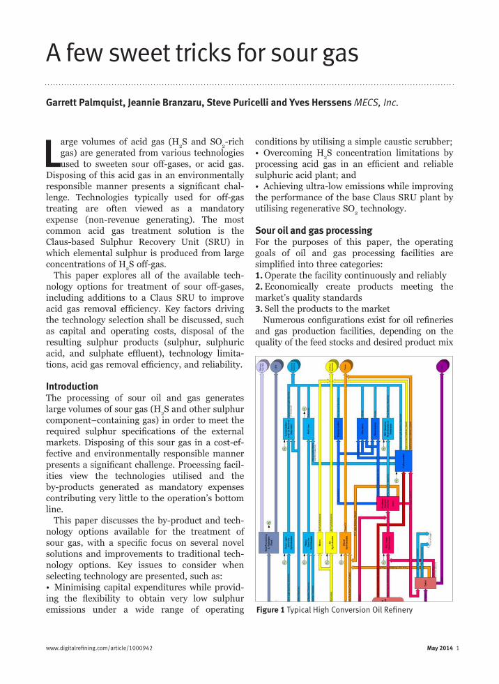
Figure 1 Typical High Conversion Oil Refinery
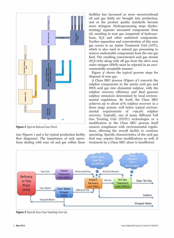
(see Figures 1 and 2 for typical production facility flow diagrams). The importance of unit opera-tions dealing with sour oil and gas within these
2 May 2014 www.digitalrefining.com/article/1000942
facilities has increased as more unconventional oil and gas fields are brought into production, and as the product quality standards become more stringent. Hydroprocessing steps (hydro-treating) separate unwanted components from oil, resulting in sour gas comprised of hydrocar-bons, H
2S and other undesired components.
Further separation and concentration of this sour gas occurs in an Amine Treatment Unit (ATU), which is also used in natural gas processing to remove undesirable components from the raw gas feed. The resulting concentrated acid gas stream (H
2S-rich) along with off gas from the site’s sour
water stripper (SWS) must be rejected in an envi-ronmentally acceptable manner.
Figure 31 shows the typical process steps for disposal of sour gas.
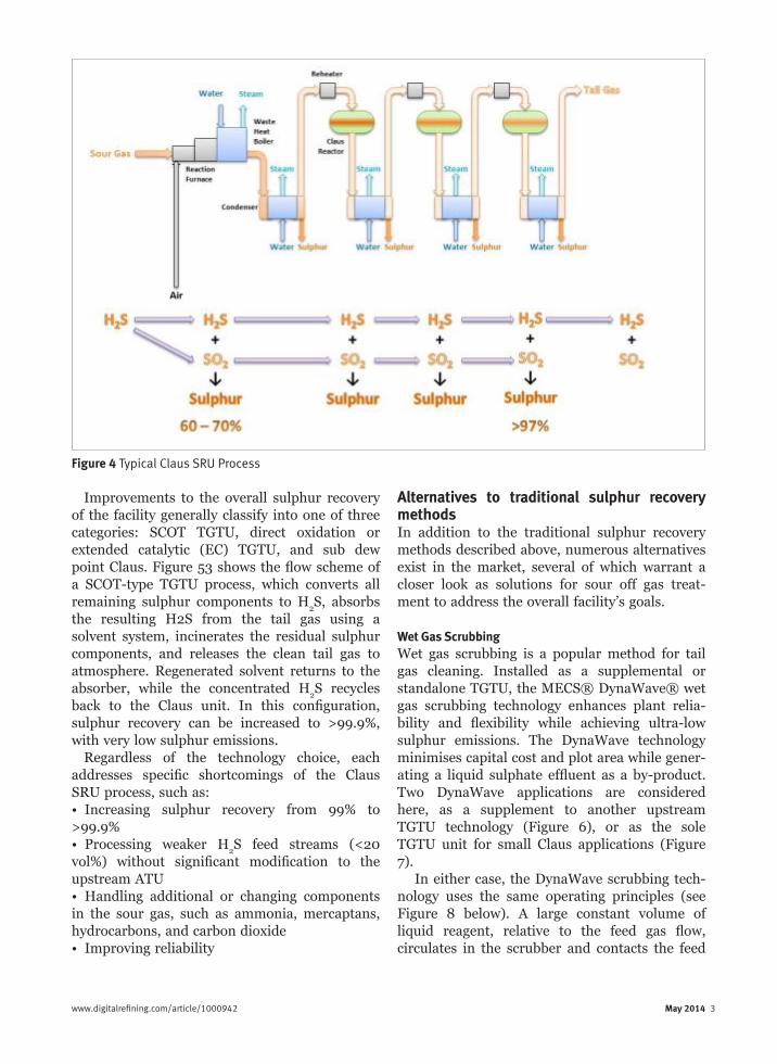
A Claus SRU process (Figure 42) converts the sulphur components in the amine acid gas and SWS acid gas into elemental sulphur, with the sulphur recovery efficiency and final gaseous sulphur emissions determined by local environ-mental regulations. By itself, the Claus SRU achieves up to about 97% sulphur recovery in a three stage system; well below typical environ-mental requirements of >99.9% sulphur recovery. Typically, one of many different Tail Gas Treating Unit (TGTU) technologies or a modification to the Claus SRU process itself ensures compliance with environmental regula-tions, allowing the overall facility to continue operating. Specific characteristics of the acid gas feed may require these modifications as well, if treatment by a Claus SRU alone is insufficient.
Figure 2 Typical Natural Gas Plant
Figure 3 Typical Sour Gas Treating Line Up
2 May 2014 www.digitalrefining.com/article/1000942
Improvements to the overall sulphur recovery of the facility generally classify into one of three categories: SCOT TGTU, direct oxidation or extended catalytic (EC) TGTU, and sub dew point Claus. Figure 53 shows the flow scheme of a SCOT-type TGTU process, which converts all remaining sulphur components to H
2S, absorbs
the resulting H2S from the tail gas using a solvent system, incinerates the residual sulphur components, and releases the clean tail gas to atmosphere. Regenerated solvent returns to the absorber, while the concentrated H
2S recycles
back to the Claus unit. In this configuration, sulphur recovery can be increased to >99.9%, with very low sulphur emissions.
Regardless of the technology choice, each addresses specific shortcomings of the Claus SRU process, such as:• Increasing sulphur recovery from 99% to >99.9%• Processing weaker H
2S feed streams (<20
vol%) without significant modification to the upstream ATU• Handling additional or changing components in the sour gas, such as ammonia, mercaptans, hydrocarbons, and carbon dioxide• Improving reliability
www.digitalrefining.com/article/1000942 May 2014 3
Alternatives to traditional sulphur recovery methodsIn addition to the traditional sulphur recovery methods described above, numerous alternatives exist in the market, several of which warrant a closer look as solutions for sour off gas treat-ment to address the overall facility’s goals.
Wet Gas ScrubbingWet gas scrubbing is a popular method for tail gas cleaning. Installed as a supplemental or standalone TGTU, the MECS® DynaWave® wet gas scrubbing technology enhances plant relia-bility and flexibility while achieving ultra-low sulphur emissions. The DynaWave technology minimises capital cost and plot area while gener-ating a liquid sulphate effluent as a by-product. Two DynaWave applications are considered here, as a supplement to another upstream TGTU technology (Figure 6), or as the sole TGTU unit for small Claus applications (Figure 7).
In either case, the DynaWave scrubbing tech-nology uses the same operating principles (see Figure 8 below). A large constant volume of liquid reagent, relative to the feed gas flow, circulates in the scrubber and contacts the feed
Figure 4 Typical Claus SRU Process
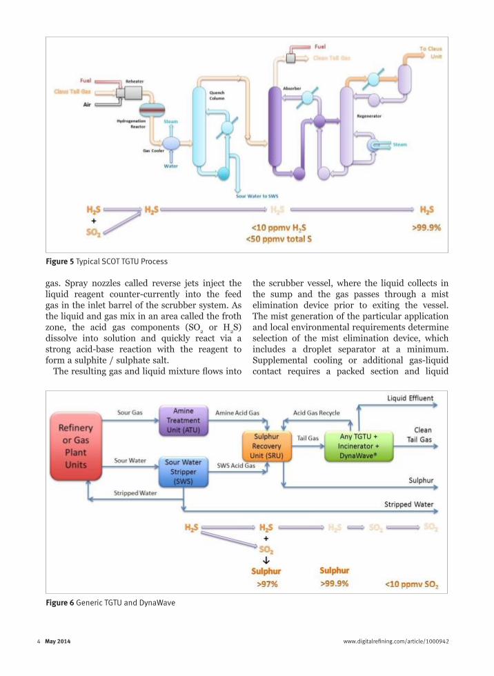
gas. Spray nozzles called reverse jets inject the liquid reagent counter-currently into the feed gas in the inlet barrel of the scrubber system. As the liquid and gas mix in an area called the froth zone, the acid gas components (SO
2 or H
2S)
dissolve into solution and quickly react via a strong acid-base reaction with the reagent to form a sulphite / sulphate salt.
The resulting gas and liquid mixture flows into
the scrubber vessel, where the liquid collects in the sump and the gas passes through a mist elimination device prior to exiting the vessel. The mist generation of the particular application and local environmental requirements determine selection of the mist elimination device, which includes a droplet separator at a minimum. Supplemental cooling or additional gas-liquid contact requires a packed section and liquid
4 May 2014 www.digitalrefining.com/article/1000942
Figure 5 Typical SCOT TGTU Process
Figure 6 Generic TGTU and DynaWave
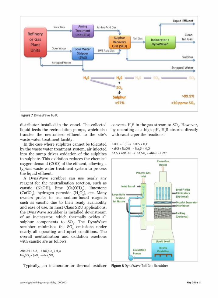
distributor installed in the vessel. The collected liquid feeds the recirculation pumps, which also transfer the neutralised effluent to the site’s waste water treatment facility.
In the case where sulphites cannot be tolerated by the waste water treatment system, air injected into the sump drives oxidation of the sulphites to sulphate. This oxidation reduces the chemical oxygen demand (COD) of the effluent, allowing a typical waste water treatment system to process the liquid effluent.
A DynaWave scrubber can use nearly any reagent for the neutralisation reaction, such as caustic (NaOH), lime (Ca(OH)
2), limestone
(CaCO3), hydrogen peroxide (H
2O
2), etc. Many
owners prefer to use sodium-based reagents such as caustic due to their ready availability and ease of use. In most Claus SRU applications, the DynaWave scrubber is installed downstream of an incinerator, which thermally oxides all sulphur components to SO
2. The DynaWave
scrubber minimises the SO2 emissions under
nearly all operating and upset conditions. The overall neutralisation and oxidation reactions with caustic are as follows:
2NaOH + SO2 →→ Na
2SO
3 + H
2O
Na2SO
3 + ½O
2 →→ Na
2SO
4
Typically, an incinerator or thermal oxidiser
converts H2S in the gas stream to SO
2. However,
by operating at a high pH, H2S absorbs directly
with caustic per the reactions:
NaOH + H2S →→ NaHS + H
2O
NaHS + NaOH →→ Na2S + H
2O
Na2S + 4NaOCl →→ Na
2SO
4 + 4NaCl + Heat
www.digitalrefining.com/article/1000942 May 2014 5 4 May 2014 www.digitalrefining.com/article/1000942
Figure 7 DynaWave TGTU
Figure 8 DynaWave Tail Gas Scrubber

The high pH required for the direct absorption of H
2S limits this method’s applicability to sour
gas containing very little CO2, as the caustic also
reacts with any CO2 present.
Table 14 provides installed cost and plant size
comparisons of several different sour gas treating configurations.
Configurations C and E in Table 1 demonstrate the much lower capital cost and equipment complexity provided by the EC and DynaWave installation, which also translates into lower maintenance costs and
increased reliability. A DynaWave installation can guarantee final SO
2 emissions as low as 5 to
10 ppmv, and operating values of ~1 ppmv have been reported.
For small Claus SRU installations of less than 25 TPD capacity, a DynaWave scrubber installed as the sole TGTU provides significant advantages compared to more complicated traditional TGTU technologies. While the operating costs related to reagent consumption and effluent disposal are relatively high, the capital cost of the installation is quite low (see Table 2). During situations when the upstream Claus SRU shuts down, the incinerator and DynaWave scrubber can process all or part of the feed gas to the unit while still meeting required environmental emission limits. Operating costs will increase significantly during this mode of operation, but the operational flexi-bility and reliability of the entire SRU system are ensured.
Developed in the 1970s by DuPont, DynaWave scrubbers have been installed in over 300 facili-ties to scrub tail gas in various industries. Within the oil and gas industry, the benefits in capital cost reduction, operating flexibility, and reliabil-ity improvements have been realised by over 20 installations.
Sulphuric Acid ProductionWhen processing sour oil and gas, producers usually decide to convert sour gas into elemental sulphur for a number of reasons. Storage and handling of elemental sulphur is fairly simple and straightforward. Global markets and infra-structure exist for selling and transporting sulphur. When market conditions are particu-
6 May 2014 www.digitalrefining.com/article/1000942
Figure 9 DynaWave Tail Gas Scrubber

6 May 2014 www.digitalrefining.com/article/1000942
larly unfavourable, sulphur can be blocked and stored on-site. However in certain situations, it may be more attractive to produce sulphuric acid from the sour gas. Proximity to a fertilizer plant or chemical facility requiring sulphuric
acid, access to established sulphuric acid trans-portation infrastructure, or existing experience may prompt a closer look at sulphuric acid production rather than the production of elemental sulphur. In these situations, the
www.digitalrefining.com/article/1000942 May 2014 7
Figure 10 SULFOX as SRU
Figure 11 SULFOX as SRU Retrofit
MECS® SULFOX™ technology offers a simple and reliable process for sour gas treatment.
A SULFOX sulphuric acid plant can achieve 99% sulphur recovery as sulphuric acid in its simplest configuration. More complicated flow schemes utilising activated carbon filters or a DynaWave tail gas scrubber can achieve much higher sulphur recovery values and ultra-low SO
2 emissions. A SULFOX plant can be installed
in lieu of a Claus SRU and TGTU (Figure 10) or as part of an integrated complex with a new or existing Claus SRU and TGTU (Figure 11, TGTU not shown for clarity). When integrated in this way, a SULFOX plant increases flexibility and reliability by debottlenecking acid gas capacity, processing SWS gas to eliminate ammonia concerns, providing additional Claus SRU tail gas clean up, and handling all acid gas when the Claus SRU is down.
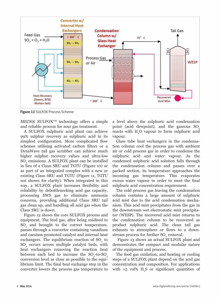
Figure 12 shows the core SULFOX process and equipment. The feed gas, after being oxidised to SO
2 and brought to the correct temperature,
passes through a converter containing vanadium and caesium-promoted catalyst and internal heat exchangers. The equilibrium reaction of SO
2 to
SO3 occurs across multiple catalyst beds, with
heat exchangers removing the reaction heat between each bed to increase the SO
2-to-SO
3
conversion level as close as possible to the equi-librium limit. The final heat exchange step in the converter lowers the process gas temperature to
a level above the sulphuric acid condensation point (acid dewpoint), and the gaseous SO
3
reacts with H2O vapour to form sulphuric acid
vapour.Glass tube heat exchangers in the condensa-
tion column cool the process gas with ambient air or cold process gas in order to condense the sulphuric acid and water vapour. As the condensed sulphuric acid solution falls through the condensation column and passes over a packed section, its temperature approaches the incoming gas temperature. This evaporates excess water vapour in order to meet the final sulphuric acid concentration requirement.
The cold process gas leaving the condensation column contains a large amount of sulphuric acid mist due to the acid condensation mecha-nism. This acid mist precipitates from the gas in the downstream wet electrostatic mist precipita-tor (WESP). The recovered acid mist returns to the condensation column to be recovered as product sulphuric acid. The clean tail gas exhausts to atmosphere or flows to a down-stream process for further SO
2 removal.
Figure 13 shows an actual SULFOX plant and demonstrates the compact and modular nature of the equipment and process.
The feed gas oxidation, and heating or cooling steps of a SULFOX plant depend on the acid gas concentration and composition. For applications with >5 vol% H
2S or significant quantities of
8 May 2014 www.digitalrefining.com/article/1000942
Figure 12 SULFOX Process Scheme

hydrocarbons or ammonia, a SULFOX HK process thermally oxidises the feed gas at high temperature (Figure 14). Excess heat from the furnace produces high pressure steam in a waste heat boiler, which cools the process gas to the required operating temperature of the down-stream catalyst. This combustion and cooling step occurs in many different sulphuric acid
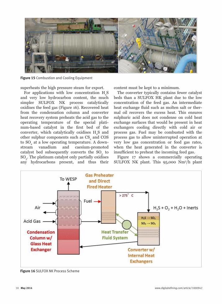
plant types, with the main differences existing in the feed types (acid gas, spent sulphate liquids, fuel), operating pressure (vacuum or positive pressure), cleanliness of the combustion prod-ucts, and recovered steam pressure. Figure 15 displays such a furnace and waste heat boiler. Excess heat from the converter heat exchangers generates additional steam in the gas cooler and
www.digitalrefining.com/article/1000942 May 2014 9 8 May 2014 www.digitalrefining.com/article/1000942
Figure 13 SULFOX Process Scheme – Actual Plant
Figure 14 SULFOX HK Combustion Process Scheme
10 May 2014 www.digitalrefining.com/article/1000942
superheats the high pressure steam for export.For applications with low concentration H
2S
and very low hydrocarbon content, the much simpler SULFOX NK process catalytically oxidises the feed gas (Figure 16). Recovered heat from the condensation column and converter heat recovery system preheats the acid gas to the operating temperature of the special plati-num-based catalyst in the first bed of the converter, which catalytically oxidises H
2S and
other sulphur components such as CS2 and COS
to SO2 at a low operating temperature. A down-
stream vanadium and caesium-promoted catalyst bed subsequently converts the SO
2 to
SO3. The platinum catalyst only partially oxidises
any hydrocarbons present, and thus their
content must be kept to a minimum.The converter typically contains fewer catalyst
beds than a SULFOX HK plant due to the low concentration of the feed gas. An intermediate heat exchange fluid such as molten salt or ther-mal oil recovers the excess heat. This ensures sulphuric acid does not condense on cold heat exchange surfaces that would be present in heat exchangers cooling directly with cold air or process gas. Fuel may be combusted with the process gas to allow uninterrupted operation at very low gas concentration or feed gas rates, when the heat generated in the converter is insufficient to preheat the incoming feed gas.
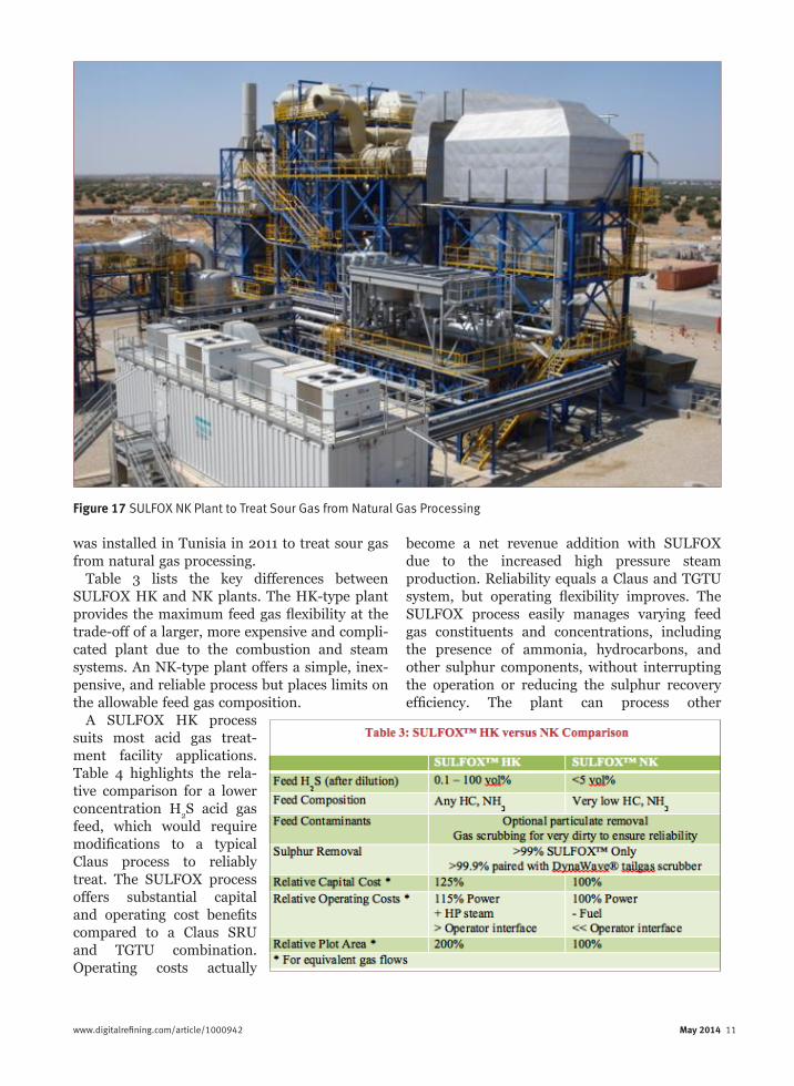
Figure 17 shows a commercially operating SULFOX NK plant. This 95,000 Nm3/h plant
Figure 15 Combustion and Cooling Equipment
Figure 16 SULFOX NK Process Scheme
10 May 2014 www.digitalrefining.com/article/1000942 www.digitalrefining.com/article/1000942 May 2014 11
become a net revenue addition with SULFOX due to the increased high pressure steam production. Reliability equals a Claus and TGTU system, but operating flexibility improves. The SULFOX process easily manages varying feed gas constituents and concentrations, including the presence of ammonia, hydrocarbons, and other sulphur components, without interrupting the operation or reducing the sulphur recovery efficiency. The plant can process other
was installed in Tunisia in 2011 to treat sour gas from natural gas processing.
Table 3 lists the key differences between SULFOX HK and NK plants. The HK-type plant provides the maximum feed gas flexibility at the trade-off of a larger, more expensive and compli-cated plant due to the combustion and steam systems. An NK-type plant offers a simple, inex-pensive, and reliable process but places limits on the allowable feed gas composition.
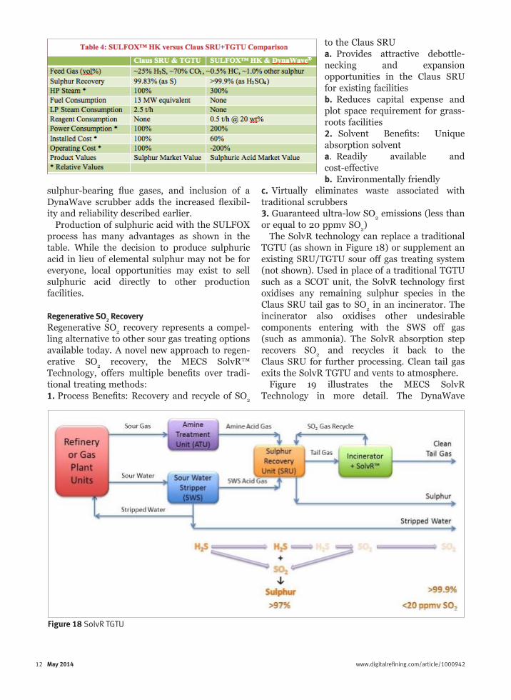
A SULFOX HK process suits most acid gas treat-ment facility applications. Table 4 highlights the rela-tive comparison for a lower concentration H
2S acid gas
feed, which would require modifications to a typical Claus process to reliably treat. The SULFOX process offers substantial capital and operating cost benefits compared to a Claus SRU and TGTU combination. Operating costs actually
Figure 17 SULFOX NK Plant to Treat Sour Gas from Natural Gas Processing
12 May 2014 www.digitalrefining.com/article/1000942
to the Claus SRUa. Provides attractive debottle-necking and expansion opportunities in the Claus SRU for existing facilitiesb. Reduces capital expense and plot space requirement for grass-roots facilities2. Solvent Benefits: Unique absorption solventa. Readily available and cost-effectiveb. Environmentally friendly
c. Virtually eliminates waste associated with traditional scrubbers3. Guaranteed ultra-low SO
2 emissions (less than
or equal to 20 ppmv SO2)
The SolvR technology can replace a traditional TGTU (as shown in Figure 18) or supplement an existing SRU/TGTU sour off gas treating system (not shown). Used in place of a traditional TGTU such as a SCOT unit, the SolvR technology first oxidises any remaining sulphur species in the Claus SRU tail gas to SO
2 in an incinerator. The
incinerator also oxidises other undesirable components entering with the SWS off gas (such as ammonia). The SolvR absorption step recovers SO
2 and recycles it back to the
Claus SRU for further processing. Clean tail gas exits the SolvR TGTU and vents to atmosphere.
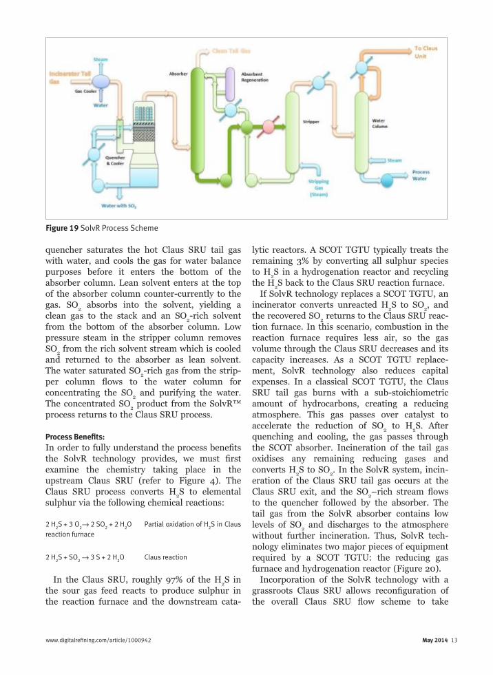
Figure 19 illustrates the MECS SolvR Technology in more detail. The DynaWave
sulphur-bearing flue gases, and inclusion of a DynaWave scrubber adds the increased flexibil-ity and reliability described earlier.
Production of sulphuric acid with the SULFOX process has many advantages as shown in the table. While the decision to produce sulphuric acid in lieu of elemental sulphur may not be for everyone, local opportunities may exist to sell sulphuric acid directly to other production facilities.
Regenerative SO2 RecoveryRegenerative SO
2 recovery represents a compel-
ling alternative to other sour gas treating options available today. A novel new approach to regen-erative SO
2 recovery, the MECS SolvR™
Technology, offers multiple benefits over tradi-tional treating methods: 1. Process Benefits: Recovery and recycle of SO
2
Figure 18 SolvR TGTU
12 May 2014 www.digitalrefining.com/article/1000942 www.digitalrefining.com/article/1000942 May 2014 13
lytic reactors. A SCOT TGTU typically treats the remaining 3% by converting all sulphur species to H
2S in a hydrogenation reactor and recycling
the H2S back to the Claus SRU reaction furnace.
If SolvR technology replaces a SCOT TGTU, an incinerator converts unreacted H
2S to SO
2, and
the recovered SO2 returns to the Claus SRU reac-
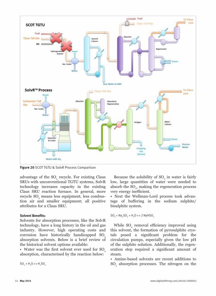
tion furnace. In this scenario, combustion in the reaction furnace requires less air, so the gas volume through the Claus SRU decreases and its capacity increases. As a SCOT TGTU replace-ment, SolvR technology also reduces capital expenses. In a classical SCOT TGTU, the Claus SRU tail gas burns with a sub-stoichiometric amount of hydrocarbons, creating a reducing atmosphere. This gas passes over catalyst to accelerate the reduction of SO
2 to H
2S. After
quenching and cooling, the gas passes through the SCOT absorber. Incineration of the tail gas oxidises any remaining reducing gases and converts H
2S to SO
2. In the SolvR system, incin-
eration of the Claus SRU tail gas occurs at the Claus SRU exit, and the SO
2–rich stream flows
to the quencher followed by the absorber. The tail gas from the SolvR absorber contains low levels of SO
2 and discharges to the atmosphere
without further incineration. Thus, SolvR tech-nology eliminates two major pieces of equipment required by a SCOT TGTU: the reducing gas furnace and hydrogenation reactor (Figure 20).
Incorporation of the SolvR technology with a grassroots Claus SRU allows reconfiguration of the overall Claus SRU flow scheme to take
quencher saturates the hot Claus SRU tail gas with water, and cools the gas for water balance purposes before it enters the bottom of the absorber column. Lean solvent enters at the top of the absorber column counter-currently to the gas. SO
2 absorbs into the solvent, yielding a
clean gas to the stack and an SO2-rich solvent
from the bottom of the absorber column. Low pressure steam in the stripper column removes SO
2 from the rich solvent stream which is cooled
and returned to the absorber as lean solvent. The water saturated SO
2-rich gas from the strip-
per column flows to the water column for concentrating the SO
2 and purifying the water.
The concentrated SO2 product from the SolvR™
process returns to the Claus SRU process.
Process Benefits:In order to fully understand the process benefits the SolvR technology provides, we must first examine the chemistry taking place in the upstream Claus SRU (refer to Figure 4). The Claus SRU process converts H
2S to elemental
sulphur via the following chemical reactions:
2 H2S + 3 O
2→ 2 SO
2 + 2 H
2O Partial oxidation of H
2S in Claus
reaction furnace
2 H2S + SO
2 → 3 S + 2 H
2O Claus reaction
In the Claus SRU, roughly 97% of the H2S in
the sour gas feed reacts to produce sulphur in the reaction furnace and the downstream cata-
Figure 19 SolvR Process Scheme
14 May 2014 www.digitalrefining.com/article/1000942
Because the solubility of SO2 in water is fairly
low, large quantities of water were needed to absorb the SO
2, making the regeneration process
very energy inefficient.• Next the Wellman-Lord process took advan-tage of buffering in the sodium sulphite/bisulphite system.
SO2 + Na
2SO
3 + H
2O ↔ 2 NaHSO
3
While SO2 removal efficiency improved using
this solvent, the formation of pyrosulphite crys-tals posed a significant problem for the circulation pumps, especially given the low pH of the sulphite solution. Additionally, the regen-eration step required a significant amount of steam.• Amine-based solvents are recent additions to SO
2 absorption processes. The nitrogen on the
advantage of the SO2 recycle. For existing Claus
SRUs with unconventional TGTU systems, SolvR technology increases capacity in the existing Claus SRU reaction furnace. In general, more recycle SO
2 means less equipment, less combus-
tion air and smaller equipment; all positive attributes for a Claus SRU.
Solvent Benefits:Solvents for absorption processes, like the SolvR technology, have a long history in the oil and gas industry. However, high operating costs and corrosion have historically handicapped SO
2
absorption solvents. Below is a brief review of the historical solvent options available:• Water was the first solvent ever used for SO
2
absorption, characterised by the reaction below:
SO2 + H
2O ↔ H
2SO
3
Figure 20 SCOT TGTU & SolvR Process Comparison
14 May 2014 www.digitalrefining.com/article/1000942 www.digitalrefining.com/article/1000942 May 2014 15
SO2 + Na
2-R ↔ Na
2-R-SO
3
When SO2 is oxidised to SO
4 in the liquid
phase, it reacts with the ionic Na+ in the solution to form Na
2SO
4. The base solvent remains
untouched, and an ion exchange step removes Na
2SO
4. This small amount of aqueous sodium
sulphate can then be discharged to the plant sewer or dried and transported as a solid waste to a municipal landfill.
Ultra-low emissions are a function of the solvent:SO
2 ratio, the number of theoretical
stages available in the absorber and the concen-tration of the SO
2 in the lean solvent. When
designing an absorber, the solvent:SO2 ratio and
absorber theoretical stages are primarily a func-tion of the inlet SO
2 concentration. In contrast,
the gas in equilibrium with the lean solvent at the top of the absorber directly controls the outlet SO
2 concentration. The ability to effec-
tively strip SO2 from the lean solvent is one of
the most crucial parameters in achieving low emissions.
Fortunately, the SolvR solvent readily releases its SO
2 with moderate temperatures (105°C) and
modest steam ratios (6-9 kg steam/kg SO2 when
targeting 20 ppmv in the absorber outlet).The SolvR solvent is one of the most unique
aspects of this novel process. This solvent is a high capacity, robust and stable solvent with minimal by-product generation. Used in food processing, the SolvR solvent is inherently safe and readily available.
SummaryMany options are available for treating sour gases, so consideration must be given to the type of by-product (sulphate effluent, sulphur or sulphuric acid), local markets for these products, shipping costs, overall sulphur recovery required and economics.
The Claus SRU process is clearly the predomi-nant choice for treating acid gases, presumably due to the well-established sulphur marketing and shipping infrastructure, ease of handling and economics. However, converting acid gases to sulphuric acid with technologies like the MECS SULFOX process presents an interesting option when sulphuric acid end-users are nearby or the acid gas characteristics make processing in a Claus SRU unit unattractive.
amine has a double bond available, which attracts H
2 in water and produces an OH- ion,
increasing alkalinity. When sulphurous ions are present they preferentially bond with the amine’s electron pair and release H
2 ions.
SO2 + H
2O ↔ H
2++SO
3= + R-N: ↔ R-N:SO
3 + H
2++
The overall simplified chemistry is:
R-N:SO3 ↔ SO
2
Amine solvents resulted in good SO2 removal
efficiency, however, as with any sulphite system, oxidation occurs resulting in the formation of SO
4. This SO
4 reacts with the amine-based
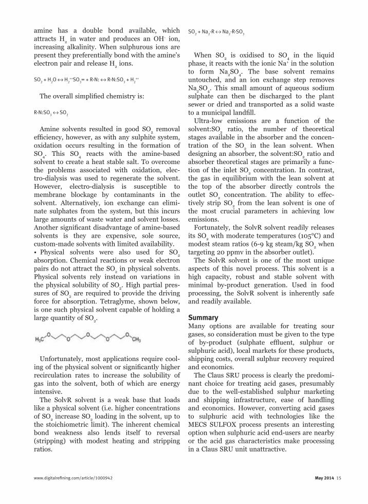
solvent to create a heat stable salt. To overcome the problems associated with oxidation, elec-tro-dialysis was used to regenerate the solvent. However, electro-dialysis is susceptible to membrane blockage by contaminants in the solvent. Alternatively, ion exchange can elimi-nate sulphates from the system, but this incurs large amounts of waste water and solvent losses. Another significant disadvantage of amine-based solvents is they are expensive, sole source, custom-made solvents with limited availability.• Physical solvents were also used for SO
2
absorption. Chemical reactions or weak electron pairs do not attract the SO
2 in physical solvents.
Physical solvents rely instead on variations in the physical solubility of SO
2. High partial pres-
sures of SO2 are required to provide the driving
force for absorption. Tetraglyme, shown below, is one such physical solvent capable of holding a large quantity of SO
2.
Unfortunately, most applications require cool-ing of the physical solvent or significantly higher recirculation rates to increase the solubility of gas into the solvent, both of which are energy intensive.
The SolvR solvent is a weak base that loads like a physical solvent (i.e. higher concentrations of SO
2 increase SO
2 loading in the solvent, up to
the stoichiometric limit). The inherent chemical bond weakness also lends itself to reversal (stripping) with modest heating and stripping ratios.
16 May 2014 www.digitalrefining.com/article/1000942
The Claus SRU process’s attractiveness also results from its status as an open art, well-proven, and robust process. However, Claus SRUs suffer from equilibrium limitations, neces-sitating a tail gas clean-up step to meet most emission requirements. While SCOT reigns as the TGTU market leader, site specific conditions may favour technologies like DynaWave tail gas scrubbing. Furthermore, new technologies, like SolvR Regenerative SO
2 Recovery, introduce a
disruptive potential and can reshape the basic Claus SRU configuration.
In summary, there are many new options for treating Claus SRU tail gas. In the near term, SCOT will continue to be the incumbent although site specific conditions and project economics will make alternatives like DynaWave wet gas scrubbing and SULFOX wet gas sulphu-ric acid production interesting alternatives. As SolvR regenerative SO
2 scrubbing matures, its
attributes may significantly shift economics to its favour. Like the sour lemon, new technology
could provide the sweetness needed to turn lemons into lemonade.
References1. SULPHUR Number 336, “Sulphur management in refineries” (September-October 2011)2. Mbeychok, commons.wikimedia.org/wiki/File:Claus_Sulfur_Recovery.png (2 March 2012)3. SCOT® Fact Sheet, www.shell.com/globalsolutions (2011)4. SULPHUR Number 326, “Low cost and reliable sulphur recovery” (January-February 2010)
LINKS
More articles from: DuPont Clean Technologies
More articles from the following categories: Emissions Control Heavy/Sour CrudesRevamps, Shutdowns and TurnaroundsSafety, Health, Environment and Quality Sulphur Removal, Recovery & Handling
Related Documents