ARTICLE A Fe 3 N/carbon composite electrocatalyst for effective polysulfides regulation in room- temperature Na-S batteries Yuruo Qi 1,5 , Qing-Jie Li 2,5 , Yuanke Wu 1 , Shu-juan Bao 1 , Changming Li 1 , Yuming Chen 2,3 ✉ , Guoxiu Wang 4 ✉ & Maowen Xu 1 ✉ The practical application of room-temperature Na-S batteries is hindered by the low sulfur utilization, inadequate rate capability and poor cycling performance. To circumvent these issues, here, we propose an electrocatalyst composite material comprising of N-doped nanocarbon and Fe 3 N. The multilayered porous network of the carbon accommodates large amounts of sulfur, decreases the detrimental effect of volume expansion, and stabilizes the electrodes structure during cycling. Experimental and theoretical results testify the Fe 3 N affinity to sodium polysulfides via Na-N and Fe-S bonds, leading to strong adsorption and fast dissociation of sodium polysulfides. With a sulfur content of 85 wt.%, the positive electrode tested at room-temperature in non-aqueous Na metal coin cell configuration delivers a reversible capacity of about 1165 mA h g -1 at 167.5 mA g -1 , satisfactory rate capability and stable capacity of about 696 mA h g -1 for 2800 cycles at 8375 mA g -1 . https://doi.org/10.1038/s41467-021-26631-y OPEN 1 Key Laboratory of Luminescence Analysis and Molecular Sensing, Ministry of Education, Faculty of Materials and Energy, Southwest University, Chongqing 400715, PR China. 2 Department of Nuclear Science and Engineering, Massachusetts Institute of Technology, Cambridge, MA 02139, USA. 3 College of Environmental Science and Engineering, Fujian Normal University, Fuzhou 350007, PR China. 4 Center for Clean Energy Technology, University of Technology Sydney, Sydney, NSW 2007, Australia. 5 These authors contributed equally: Yuruo Qi, Qing-Jie Li. ✉ email: [email protected]; [email protected]; [email protected] NATURE COMMUNICATIONS | (2021)12:6347 | https://doi.org/10.1038/s41467-021-26631-y | www.nature.com/naturecommunications 1 1234567890():,;

Welcome message from author
This document is posted to help you gain knowledge. Please leave a comment to let me know what you think about it! Share it to your friends and learn new things together.
Transcript

ARTICLE
A Fe3N/carbon composite electrocatalyst foreffective polysulfides regulation in room-temperature Na-S batteriesYuruo Qi1,5, Qing-Jie Li2,5, Yuanke Wu1, Shu-juan Bao1, Changming Li 1, Yuming Chen2,3✉,
Guoxiu Wang 4✉ & Maowen Xu 1✉
The practical application of room-temperature Na-S batteries is hindered by the low sulfur
utilization, inadequate rate capability and poor cycling performance. To circumvent these
issues, here, we propose an electrocatalyst composite material comprising of N-doped
nanocarbon and Fe3N. The multilayered porous network of the carbon accommodates large
amounts of sulfur, decreases the detrimental effect of volume expansion, and stabilizes the
electrodes structure during cycling. Experimental and theoretical results testify the Fe3N
affinity to sodium polysulfides via Na-N and Fe-S bonds, leading to strong adsorption and fast
dissociation of sodium polysulfides. With a sulfur content of 85 wt.%, the positive electrode
tested at room-temperature in non-aqueous Na metal coin cell configuration delivers a
reversible capacity of about 1165 mA h g−1 at 167.5 mA g−1, satisfactory rate capability and
stable capacity of about 696mA h g−1 for 2800 cycles at 8375mA g−1.
https://doi.org/10.1038/s41467-021-26631-y OPEN
1 Key Laboratory of Luminescence Analysis and Molecular Sensing, Ministry of Education, Faculty of Materials and Energy, Southwest University, Chongqing400715, PR China. 2 Department of Nuclear Science and Engineering, Massachusetts Institute of Technology, Cambridge, MA 02139, USA. 3 College ofEnvironmental Science and Engineering, Fujian Normal University, Fuzhou 350007, PR China. 4 Center for Clean Energy Technology, University of TechnologySydney, Sydney, NSW 2007, Australia. 5These authors contributed equally: Yuruo Qi, Qing-Jie Li. ✉email: [email protected]; [email protected];[email protected]
NATURE COMMUNICATIONS | (2021) 12:6347 | https://doi.org/10.1038/s41467-021-26631-y | www.nature.com/naturecommunications 1
1234
5678
90():,;

Room-temperature sodium–sulfur (RT Na-S) batteries holdsignificant promise for large-scale application due to theabundance, nontoxicity, low cost and high theoretical
capacity of both electrodes (Na anode and S cathode)1–3. Similarto Li–S batteries, Na–S batteries are also facing several challenges,such as low sulfur loading, unsatisfactory reversible capacity,inadequate rate capability, and rapid capacity fading1–3. Theseproblems are typically triggered by the following intractableissues, which include the insulating nature of sulfur and its dis-charged products, the sluggish electrochemical reactivity of solidsulfur with sodium, the high solubility of polysulfides in theelectrolyte4–6 and the huge volume expansion during the dis-charge/charge process.
In attempting to address these problems, constructing hier-archical sulfur hosts is highly desirable. Nanocarbons7–9 withexcellent electronic conductivity and large surface areas areemployed to balance the inferior electronic conductivity of sulfurand physically confine sodium polysulfides (NaPSs). However,the nonpolar feature of these carbon materials signifies insuffi-cient mutual interaction to completely eliminate the shuttling ofpolysulfides. Subsequently, polar materials with intrinsic affinityto sulfur/polysulfides are introduced to anchor polysulfides che-mically and thus enhance the cycling stability. Recently, electro-catalysts (including metals, metal oxides, metal sulfides, etc.) areproposed to accelerate the conversion kinetics of polysulfides andsuppress the shuttling of polysulfides based on the strong catalyticactivity10–12. Metal nitrides, featured with low cost, excellentchemical stability, good conductivity, and strong adhesion topolysulfides, have been widely investigated in Li–S batteries13–15;however, such metal nitrides have been rarely applied in RT Na–Sbatteries and their effectiveness and associated mechanisms in RTNa–S batteries remain unclear.
A further issue for most reported studies is the low sulfurcontent which could hinder the practical application. As Na–Sbatteries development is in its infancy, the attention to increasesulfur loading of Na–S cathodes is still insufficient. It has beenacknowledged that 70% sulfur loading is critical to achieve high-energy-density Li–S batteries16–19. Being on a par with the energydensity of Li–S batteries, a sulfur loading more than 70% in Na–Sbatteries is indispensable due to the larger atomic mass of Na.However, without proper cathode design, the massive load ofsulfur will form a thick insulating layer, which eventually reducesthe utilization rate and reaction kinetics. What’s worse, thenotorious shuttle effect of NaPSs will be exacerbated and result inworse cycling stability. Therefore, it is an urgent need to explorethe rational design of hierarchical cathodes, which can synergis-tically inhibit the shuttle of NaPSs and enhance the electro-chemical reactivity of sulfur with sodium under high-sulfurcontent.
In this research work, we propose a highly efficient Fe3N cat-alyst on N-doped multilayered carbon networks (NMCN) thatenables strong adsorption and fast dissociation of NaPSs foradvanced Na–S batteries. The NMCN featured with a hierarchicalpore structure can accommodate massive sulfur, suppress volumeexpansion, and stabilize the cycling process. As far as we know,there has been no previous study employing nitrides in cathodehosts for Na–S batteries. The as-prepared S@Fe3N-NMCN cath-ode can be directly used as a freestanding electrode without anyother binders, conductive additives and current collectors, whichsignificantly reduces the time and cost for assembling the battery.Both the pores within nanofibers and the interstice between layerscan provide adequate space for sulfur loading. Fe3N shows pro-minent affinity to NaPSs via Na–N and Fe–S bonding, leading toefficient NaPSs dissociation. Benefiting from these structural andcompositional advantages, a high-sulfur loading of 85wt.%(2.6 mg cm−2) is achieved. Importantly, the S@Fe3N-NMCN
cathode delivers satisfactory electrochemical performance in RTNa–S batteries, in terms of specific capacity (1165.9 mA h g−1 at167.5 mA g−1), rate capability (658.4 mA h g−1 at 16750mA g−1),and cycling stability (almost no capacity attenuation after 2800cycles at 8375mA g−1). The robust hierarchical cathode design inthis work demonstrates effectiveness in developing a stable cath-ode with high mass loading and stable kinetics, which can begeneralized to other batteries systems. A simple graphical sketch ofthe Na–S cell proposed and the advantages of the S@Fe3N-NMCNcathode are shown in Fig. 1a, which embodies the underlyingreasons for the boosted performance.
Results and discussionCharacterization of Fe3N-NMCN and S@Fe3N-NMCN. Toobtain a promising reservoir for sulfur (Fe3N-NMCN), com-mercialized bacterial celluloses (BC) infiltrated with FeCl3·6H2Owere carbonized at 300 °C for 1 h and 800 °C for 2 h under a low-pressure NH3 flow. The purpose of the treatment at the lowtemperature of 300 °C is to stabilize the structure by evaporatingthose volatile species in the BC precursor (such as CO, CO2,methanol, and acetic acid)20, before the final carbonization of BCat a high temperature of 800 °C. XRD and Raman results inSupplementary Fig. 1a–b confirm that the bare BC precursor canbe precarbonized at 300 °C and the structure remains almostunchanged at the elevated temperature.
As listed by elemental analysis in Supplementary Table 1, thepristine BC consists of 46.86 wt.% C, 0.12 wt.% N, 46.37 wt.% Oand 6.65 wt.% H. The small amount of “intrinsic” nitrogen atoms(0.12 wt.%) come from the residual nitrogen-containing com-pounds left by the culture media and secretions. When treated at300 °C, most of the O/H volatilizes and a large amount of N(31.45 wt.%) is doped. As the temperature goes up, the amount ofN/O/H reduces while that of C increases remarkably. Finally, thecontent of C, N, O and H in BC-800 are 89.77 wt.%, 6.45 wt.%,2.56 wt.% and 1.22 wt.%, respectively.
XPS analyses (Supplementary Figure 1c and SupplementaryTable 2) manifest that the amount of O=C species increases whilethose of O–C and O–C–O decrease dramatically when thetemperature is raised. The final BC-800 is characterized bydominant O=C groups which have been reported to boost theaffinity between the carbon anode and sodium ions21,22, afavorable feature for performance enhancement. Meanwhile,pyridinic and pyrrolic N are two main N functional groups thatcan strongly bond to polysulfides and increase electronicconductivity23–25. FESEM images in Supplementary Figure 1dshow that these composite fibers become thinner with theincreasing temperature. In addition, the FeCl3·6H2O turns intoFe2O3 under the low-temperature treatment (around 300 °C) andthen fully converts into Fe3N at 800 °C (Supplementary Fig. 2).
The as-obtained Fe3N-NMCN composite retains the multi-layered morphology of the pristine BC (Fig. 1b and Supplemen-tary Fig. 3a–c) and maintains a self-supporting structure (inset ofSupplementary Fig. 3a) with a thickness around 350 µm(Supplementary Fig. 3d). Each layer is interconnected by nano-sized carbon fibers with a wide diameter distribution around10–100 nm (Fig. 1c and Supplementary Fig. 3e–f). The TEMimages in Fig. 1d and Supplementary Fig. 1g suggest thatnanoparticles with a size of 3–10 nm are tightly implanted inthese carbon nanofibers. The intertwined self-standing multilayercarbon networks can create a continuous pathway for electrons/ions (the electronic conductivity of carbonized bacterial celluloseaerogel can reach 20.6 S m−1 26) and accommodate the volumechange of active materials. Plentiful macropores generated by theinterconnection of carbon layers (Fig. 1b and SupplementaryFig. 3h–i) can offer more voids to achieve high-sulfur loading.
ARTICLE NATURE COMMUNICATIONS | https://doi.org/10.1038/s41467-021-26631-y
2 NATURE COMMUNICATIONS | (2021) 12:6347 | https://doi.org/10.1038/s41467-021-26631-y | www.nature.com/naturecommunications

Brunauer-Emmert-Teller (BET) analysis and correspondingpore-size distribution were used for a more detailed investigationof the porous structure, as shown in Fig. 1e and SupplementaryFig. 4. The BET surface area, total pore volume, microporesvolume, and mesopores volume of the Fe3N-NMCN composite,BC carbonized in Ar (abbreviated as BC-Ar) and BC carbonized inNH3 (abbreviated as BC-NH3) are compared in SupplementaryTable 3. The BET-specific surface area of the Fe3N-NMCNcomposite is as high as 535m2 g−1, much higher than those ofBC-NH3 (425m2 g−1) and BC-Ar (411m2 g−1), providing prolificspace for accommodating vast amount of sulfur. Moreover, thecomposite possesses a mixture of micropores (0.17 cm3 g−1),mesopores (0.38 cm3 g−1), and macropores (inset of Fig. 1e). Ithas been reported that the synergistic employment of hierarchicalpores is an effective strategy to immobilize different types of Sspecies and enable high-sulfur content2,27,28. Micropores arepromising reservoirs for accommodating small S molecules andretaining NaPSs. However, the limited number of microporesalways restricts the elevation of S content. Mesopores/macropores
can help enhance sulfur encapsulation and then realize a high Sloading rate. Moreover, mesopores/macropores would greatlyaccelerate the electron/ion diffusion and offer enough space for thevolumetric expansion of sulfur. Hence, the high specific surfacearea, in conjunction with the hierarchical pore structure, makesthe composite a promising high-sulfur-content host.
The phase information of these nanoparticles was firstlyinvestigated by X-ray diffraction (XRD) technique (Fig. 1f). Fivecharacteristic peaks at 37.9°, 41.0°, 43.3°, 57.1°, and 68.7° areascribed to the (110), (002), (−1−11), (−1−12), and (300)reflections of crystalline Fe3N (PDF: 01-073-2101) with ahexagonal P312 space group29. The distinct lattice fringes witha d-spacing of 0.208 nm displayed by the high-resolution TEM(HRTEM) image (Fig. 1g) conforms to the (−1,−1,1) lattice planeof Fe3N. The randomly oriented short carbon layers shown inFig. 1g demonstrate the non-graphitized nature of the as-obtainedcarbon material. Besides, some defects can be observed mainlydue to the N doping30,31, as indicated by the yellow arrow. Thedisordered structure, together with abundant defects, contributes
Fig. 1 Characterization of Fe3N-NMCN and S@Fe3N-NMCN. a Graphical sketch of the current Na–S cell and the function of the S@Fe3N-NMCN cathode.b–h SEM (b–c), TEM (d), adsorption isotherm (e), pore-size distribution (inset of e), XRD (f), HRTEM (g), N 1 s and Fe 2p spectra (h) of Fe3N-NMCN.i–k TG curve (i), Raman spectrum (j), and EDS mapping images (k) of S@Fe3N-NMCN.
NATURE COMMUNICATIONS | https://doi.org/10.1038/s41467-021-26631-y ARTICLE
NATURE COMMUNICATIONS | (2021) 12:6347 | https://doi.org/10.1038/s41467-021-26631-y | www.nature.com/naturecommunications 3
favorably to the diffusion of sodium ions as well as theadsorption/catalytic reaction between Fe3N and NaPSs.
X-ray photo-electron spectroscopy (XPS) (Fig. 1h) is anotherindication of Fe3N. In N 1s spectrum, a distinct Fe-N peak can bedistinguished at 399.5 eV32–34. More importantly, Fe 2p spectrumexhibits a peak ascribed to Fe3N32–34 at the binding energy of706.9 eV. Peaks at binding energies of 709.4/722.5 and 711.9/724.7 eV are originated from Fe2+-N/O and Fe3+-N/O, due to thesurface oxidation of the sample. Peaks at binding energies of715.8 and 728.9 eV are satellite peaks. The existence of Fe3N isalso supported by the Raman spectrum in SupplementaryFigure 5, in which peaks at 211, 280, and 383 cm−1 are assignedto Fe3N according to the previous report35. The amorphousfeature of carbon fibers is also revealed by the broad D/G bands at1339/1591 cm−1. Furthermore, the N 1s XPS spectrum verifiesthe existence of nitrogen-containing functional groups introducedduring the NH3 treatment process, including oxidized-N,graphitic-N, pyrrolic-N, pyridinic-N at binding energies of403.6, 401.9, 400.7, 398.2 eV, respectively. It is believed that thedoped N especially pyridinic and pyrrolic nitrogen can bondstrongly to polysulfides and increase electronic conductivity23–25.The content of Fe3N in the Fe3N-NMCN composite is 11 wt.%,according to TGA tests (Supplementary Fig. 6). In addition, basedon the elemental analysis in Supplementary Table 4, the doped Nin Fe3N-NMCN is calculated to 9.36 wt.%, higher than those inBC-NH3 (6.45 wt.%) and BC-Ar (0.34 wt.%). The XPS depthprofiling results (Supplementary Fig. 7) after 0, 60, 120, 180 s ofsputtering further demonstrate that both the N-doping and Fe3Nare distributed uniformly through the whole matrix.
The above results suggest the successful embedding of Fe3N intoN-doped multilayer carbon networks (NMCN), constructing aFe3N-NMCN composite as a high-loading host for Na–S batteries.First, the micropores/mesopores in nanofibers and the mesopores/macropores between layers can offer adequate space for sulfurloading, which guarantees the target of high-sulfur content.Second, the electronic conductivity (0.1–1.0 × 10⁻⁵ S cm−1)36,high ionic diffusion ability (1.7–3.6 × 10⁻¹³ cm2 s−1)37 and polarsurface of Fe3N nanoparticles would endow the as-proposedcathode excellent reaction kinetics and facilitate the immobiliza-tion/transformation of polysulfides. Third, the nano-sized N-dopedcarbon fibers can offer interconnected conductive networks for therapid migration of electrons and assist the adsorption/conversionof NaPSs.
Thus, we can load very high-sulfur content up to 85 wt.%(2.6 mg cm−2) into the Fe3N-NMCN composite (Fig. 1i) througha melting-diffusion method. The sulfur loading allows highspecific energy for practical applications, outperforming otherstudies in which sulfur loadings are below the 50 wt.% range.Moreover, it is believed that further strategies to compress theporous S@Fe3N-NMCN cathode can render a close packing ofcarbon fibers and therefore a thinner electrode, promising forhigh-energy density (Supplementary Fig. 8). The evidentcharacteristic peaks of S8 (PDF: 00-024-0733) were observed byXRD (Supplementary Fig. 9), which certifies the successful Sdeposition and adsorption in the Fe3N-NMCN composite. Thecharacteristic peaks of carbon (at 1338, 1588 cm−1) and sulfur (at144, 213, 466 cm−1) were all detected by Raman (Fig. 1j)throughout the composite, verifying the complete and uniformpenetration of sulfur through the material. In addition, a sharpdecrease of specific surface area (32 m2 g−1) and pore volume(0.068 cm3 g−1) of the infiltrated material (Supplementary Fig. 10)suggests that a large proportion of pores are filled with sulfur. Theresidual pores will serve as an accommodation for the volumeexpansion during cycles.
FESEM and EDS mapping analyses of S@BC-Ar, S@BC-NH3,and S@Fe3N-NMCN were provided in Fig. 1k and Supplementary
Fig. 11. It is obvious that all three composites contain uniformdistribution of sulfur without forming any bulk particles evenunder such a high S loading. The mapping images confirm againthe uniform distribution of sulfur and also reveal that the self-standing structure is well preserved after S deposition. The aboveresults demonstrate that a large amount of sulfur had beensuccessfully embedded into the as-synthesized composites.
Interaction between NaPSs and Fe3N-NMCN. The capability ofthe Fe3N-NMCN composite to serve as an adsorbent for poly-sulfides was carefully probed (Fig. 2). Figure 2a compares theadsorption capability of 5 mg Fe3N-NMCN composite, GO, SuperP, BC-Ar, and BC-NH3 in Na2S6-DOL/Diglyme solution (deepyellow color without any adsorbents). The color of the solutionwith Super P and BC-Ar remains almost unchanged, which issimilar with most of the previous reports27,28,38 that used non-polar carbon host materials. In contrast, a moderate adsorptionability to polysulfides is exhibited by BC-NH3 (comparable to thatof GO), as demonstrated by the slight decoloration feature of thesolution including BC-NH3, which would be resulted from thedoping nitrogen (especially the pyridinic and pyrrolic N) incarbon fibers and its high surface area. Notably, the incorporationof Fe3N dots (the Fe3N-NMCN composite) enables a significantlyrapid color fading in only 10 min, indicating a strong adsorptionability for polysulfides. Density functional theory (DFT) calcula-tions were carried out to elucidate the strong binding interplaybetween Fe3N and polysulfides. It is demonstrated that Fe3N canprompt strong adsorption and fast dissociation of sodium poly-sulfides. While the Fe3N dots play a dominant role in theadsorption of polysulfides, the contribution of doping N can notbe ignored, as seen in the moderate color fading of the Na2S6-DOL/Diglyme solution (BC-NH3). Together, the synergistic effectof Fe3N dots, doped N, and large surface area with abundantpores provides an effective strategy to address the issue of poly-sulfide shuttling.
UV–Vis spectra further support the above results, as shown inFig. 2b. The original solution presents two broad bands at 424/612 nm that completely vanish after adsorbed by Fe3N-NMCNfor 24 h. These results prove the adsorption ability of theFe3N-NMCN composite to polysulfides, which can suppress theshuttling of polysulfides and ultimately enhance cycling stability.To verify whether the observed change in UV–Vis spectra iscaused by adsorption or chemical reaction with precipitation ofS-containing species, we analyzed the powders after 24 h ofadsorption by XRD, SEM, and EDS. As shown in SupplementaryFig. 12a, the XRD patterns show no other peaks other than the(002) diffraction peak at ~26.0° (due to the amorphous carbon)and the peaks corresponding to Fe3N in Fe3N-NMCN. Thissuggests that no new compounds form as a result of chemicalreactions. Furthermore, SEM and EDS mapping images inSupplementary Fig. 12b–i demonstrate that there is no aggrega-tion and all elements are uniformly dispersed in these substrates.The above results thus verify that the changes in UV–Vis spectrashould be originated from the adsorption of Na2S6.
Furthermore, XPS spectra of the bare Fe3N-NMCN powderand the Fe3N-NMCN-Na2S6 composite were analyzed toinvestigate the underlying adsorption principles. An evidentNa–N peak emerges at 1074.7 eV (Fig. 2c), besides the signalarisen from polysulfides (1071.7 eV). Concurrently, all peaks inthe N 1s spectrum (Supplementary Fig. 13) move slightly tohigher binding energies, although the shape of the spectrumremains basically unchanged. In addition, polar Fe-S bondsappear in the S 2p (159.3/160.5 eV, Fig. 2d) and Fe 2p spectrum(714.4/727.2 eV, Fig. 2e), which is helpful for immobilizingpolysulfides. The peaks located at 164.1/165.4 eV in S 2p
ARTICLE NATURE COMMUNICATIONS | https://doi.org/10.1038/s41467-021-26631-y
4 NATURE COMMUNICATIONS | (2021) 12:6347 | https://doi.org/10.1038/s41467-021-26631-y | www.nature.com/naturecommunications

spectrum correspond to S-S bonds, while peaks at 168.4/169.7 eVare from the oxidized sulfates. Based on the above analyses, theFe3N-NMCN exhibits both sodiophilic (Na–N bonds) andsulfiphilic (Fe–S bonds) affinity with NaPSs, making it anattractive Na–S host.
To evaluate the catalytic effect of Fe3N-NMCN on polysulfidestransformation, cyclic voltammetry (CV) curves of symmetriccells with an electrolyte formed by Na2S6-DOL/Diglyme weregathered (Fig. 2f). The symmetric cells with both BC-NH3 andSuper P exhibit low response currents without any staged peaks.In Metal-S batteries, well-defined redox peaks with small voltagedifferences signify excellent catalytic activity in the kineticconversion of polysulfides. However, staged redox peaks insymmetric cells are rarely observed in the Na–S batteryliteratures10. In contrast, the CV of Fe3N-NMCN shows evidentcurrent response and three pairs of well-defined peaks (at 0.24/−0.24, −0.08/0.08, and −0.46/0.46 V, respectively). As Na2S6 isthe only active reactant, the peak located at −0.08 V is assigned tothe reduction from Na2S6 to short-chain NaPSs while the peak at−0.46 V is originated from the conversion of short-chain NaPSsto Na2S. Consequently, the peak at 0.24 V corresponds to the
reduction of S8 to Na2S6. Notably, the polarization of theFe3N-NMCN electrode (0.16 V) is as small as those reported inthe literature for Li-S batteries39,40. Overall, the high currentresponse, well-defined peaks, and small polarization betweenredox peaks all refer to the strong catalytic ability of theFe3N-NMCN electrode, which effectively accelerates the electro-chemical transformation of NaPSs.
The resistance of the Fe3N-NMCN electrode is low (71 Ω forFe3N-NMCN vs. 95 Ω for BC-NH3 and 185 Ω for Super P,Fig. 2g). This figure certifies that the electronic conductivity andinterfacial affinity between Fe3N-NMCN and polysulfides areeffectively enhanced. This would facilitate the surface diffusionand subsequent conversion of polysulfides. The accelerateddynamics is also reflected by discharge/charge curves of the as-assembled Na–S cells (Fig. 2h), where the S@Fe3N-NMCNcathode shows smaller polarizations. Correspondingly, morestaged plateaus along with larger specific capacities are exhibitedby the S@Fe3N-NMCN cathode. Likewise, the CV curves ofS@Fe3N-NMCN in Fig. 2i present sharper peak profiles withmuch larger currents, suggesting the kinetics advantage ofS@Fe3N-NMCN for the conversion process.
Fig. 2 Interaction between NaPSs and Fe3N-NMCN. a Optical images of the blank Na2S6 solution and solutions with Fe3N-NMCN, BC-NH3, BC-Ar, GO,and Super P after 10min and 24 h. b UV–Vis spectra of the blank solution and solutions with Fe3N-NMCN, BC-NH3, and Super P after 24 h. c, d Na 1s (c)and S 2p (d) XPS spectra after infiltrated with Na2S6. e Comparison of Fe 2p XPS spectra before and after Na2S6 adsorption. f, g CV curves (f) and EISspectra (g) of symmetric cells with Fe3N-NMCN, BC-NH3, and Super P as cathodes. h, i Comparison of voltage-capacity curves at 167.5 mA g−1 (h) and CVcurves at 0.2 mV s−1 (i) between S@Fe3N-NMCN and S@BC-NH3.
NATURE COMMUNICATIONS | https://doi.org/10.1038/s41467-021-26631-y ARTICLE
NATURE COMMUNICATIONS | (2021) 12:6347 | https://doi.org/10.1038/s41467-021-26631-y | www.nature.com/naturecommunications 5

DFT calculations and AIMD simulations. To gain further insighton the catalytic performance of Fe3N in Na–S batteries, a theoreticalinvestigation based on DFT calculations41–45 was conducted. The(−1−11) plane of Fe3N was representatively chosen for calculationaccording to our XRD and TEM observations. The adsorptionenergy (Ead) was defined as Ead= Esub+molecule − Esub − Emolecule,where Esub+molecule, Esub, and Emolecule are the total potential energiesof the substrate adsorbing a molecule, the substrate and the isolatedmolecule, respectively. Numerous geometries of Na2Sn (n= 1, 2, 4,6 and 8) on Fe3N(−1−11) were investigated and typical config-urations were given in Fig. 3a. The calculated adsorption energies ofvarious sodium polysulfides species on the (−1−11) surface of Fe3Nwere collected in Fig. 3b. The molecular adsorption energy of Na2Son Fe3N centers at −5 eV, manifesting that Fe3N can stronglyanchor Na2S on its surface, as compared with other samples, suchas NiS212, metal46,47, Mxene48, MOFs49, and carbonmaterials12,46,47,49,50. It is also unveiled that the strong polar-polarinteraction between NaPSs and Fe3N results in an obvious dis-sociation of Na2Sn molecules. Moreover, Fe3N is prone to facilitatethe dissociation of long-chain polysulfides.
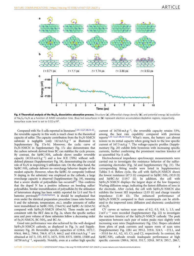
Futhermore, ab initio molecular dynamics (AIMD) simulationwas preformed to unfold the dissociation process of Na2S8following the adsorption on Fe3N. Figure 4a–c shows thestructure, differential charge density, and potential energyevolution during the dissociative adsorption of Na2S8 on Fe3N(−1−11) as a function of AIMD simulation time. Our AIMDsimulation suggests that the dissociative adsorption is dominatedby the debonding of S atoms from the molecule and subsequentrebonding to Fe3N surface, in an incremental fashion. As shown inFig. 4a–b, as the AIMD simulation proceeds, an increasingnumber of S atoms, 1S (1.1 ps) → 3S (1.74 ps) → 4S (3.86 ps) →8S (9.53 ps), debond from the molecule and form new bonds withthe Fe3N substrate. Correspondingly, the total potential energy ofthe system drops in a series of steps (Fig. 4c). During thedissociation process, charges are transferred to directional regionsnear an S atom and three nearest Fe atoms, forming new bondsbetween the S atom and the Fe3N substrate, in line with the XPSresult in Fig. 2c–e. All S atoms from Na2S8 have adsorbed on theFe3N surface in ~9.53 ps and then the Na2S8 molecule iscompletely dissociated with an energy drop of about 20 eV. Thesefindings highlight that the Fe3N delivers a powerful interactionwith NaPSs and can catalyze the dissociation of polysulfides.
Electrochemical energy storage performances of theNa–S@Fe3N-NMCN cell. We expect the above S@Fe3N-NMCNwith well-designed structure and critical functional componentsto be a desirable positive electrode active material for RT Na–Sbatteries. The redox behavior was first examined by CV with thevoltage range from 2.8 to 0.5 V at a scan rate of 0.2 mV s−1
(Fig. 5a). In the first cathodic process, only a broad peak isobserved at the voltage range of 1.5–0.8 V, while several well-defined oxidative peaks (at 2.13, 2.01, 1.87, and 1.62 V) emerge inthe following charge process. The redox behavior in the followingcycles is very different from that in the first cycle, which might berooted in the decomposition of electrolytes to form solid elec-trolyte interphase (SEI) and different reaction process due to theelectrochemically activation of S/polysulfides51. As a contrast, theBC-NH3 was loaded with sulfur and employed as a cathode(S@BC-NH3) for Na–S batteries (Supplementary Fig. 14). TheS@BC-NH3 cathode delivers different CV curves (SupplementaryFig. 15) with S@Fe3N-NMCN. Two broad peaks (1.56, 1.05 V) areobserved during the first cathodic process, while a sharp peak at1.90 V and a broad peak at 1.73 V arise in the following chargeprocess. Besides, the S@BC-NH3 cathode displays smaller currentresponse and larger polarization. The above results indicate thatthe S@Fe3N-NMCN cathode enables a more kinetically efficientredox reaction process and low intrinsic resistance.
Figure 5b is galvanostatic discharge/charge profiles of theS@Fe3N-NMCN cathode at 167.5 mA g−1 with an electrolyte/sulfur (E/S) ratio of 18.2 µL mg−1, where the transition behavioris highly consistent with the CV results. It delivers a dischargecapacity of 1270.6 mA h g−1 and a charge capacity of 1165.9 mAh g−1, reaching an initial Coulombic efficiency (ICE) of 92%.Note that the employment of the DOL/DIGLYME electrolyte canenhance the electrochemical performance of Na–S batteries asreported by previous literatures52,53 and compared withcarbonate-based electrolyte (Supplementary Fig. 16), as ether-based electrolytes always function better with metal anodes andform robust SEI. However, it was also recognized by Cui52 that asimple S/C cathode cannot retain good cycling stability in theether-based electrolyte due to the shuttle of dissolved polysulfides,and by Hassoun53 that ether-based electrolytes mitigate neitherthe polysulfide dissolution nor the polysulfide shuttle. Therefore,the elaborately designed S@Fe3N-NMCN cathode contributes tothe performance improvement.
Fig. 3 DFT calculations on the adsorption properties of Fe3N. a Typical adsorption configurations of Na2Sn (n= 1, 2, 4, 6 and 8) on Fe3N. b Calculatedadsorption energies of various Na2Sn (n= 1, 2, 4, 6 and 8) on Fe3N.
ARTICLE NATURE COMMUNICATIONS | https://doi.org/10.1038/s41467-021-26631-y
6 NATURE COMMUNICATIONS | (2021) 12:6347 | https://doi.org/10.1038/s41467-021-26631-y | www.nature.com/naturecommunications
Compared with Na–S cells reported in literatures7,10–12,27,48,54–61,the reversible capacity in this work is much closer to the theoreticalcapacity of sulfur. The capacity contribution from the Fe3N-NMCNsubstrate is negligible (only 142mA h g−1 as illustrated inSupplementary Fig. 17a–b). Moreover, the cyclic curve ofFe3N-NMCN in Supplementary Fig. 17c also demonstrates thatthe carbon network derived from BC can stabilize the cycle process.By contrast, the S@BC-NH3 cathode shows smaller reversiblecapacity (413.0mAh g−1) and a low ICE (70%) without well-defined plateaus (Supplementary Fig. 18), demonstrating the crucialrole of Fe3N in improving S utilization rate. On the other hand, theS@BC-NH3 cathode delivers no overcharge behavior despite of themodest capacity. However, when the S@BC-Ar composite (withoutN doping in the substrate) was employed as the cathode, a largeovercharge capacity is observed (Supplementary Fig. 19), meaningthat a severe shuttle of polysulfides has occurred62. This confirmsthat the doped N has a positive influence on bonding sulfur/polysulfides. Similar immobilization of polysulfides by the utilizationof heteroatom doping has been widely reported for Li-S and Na–Sbatteries previously23–25,28,54,63,64. It should be emphasized thateven under the identical preparation procedure (mass ratio betweenS and the substrate, temperature, etc.), smaller amounts of sulfurwere immobilized in S@BC-NH3 (74wt.%) and S@BC-Ar (62wt.%)compared with S@Fe3N-NMCN (85wt.%). These results are wellconsistent with the BET data in Fig. 2a, where the specific surfacearea and pore volume of these substrates follow a decreasing orderof Fe3N-NMCN, BC-NH3, and BC-Ar.
Good rate performance was also achieved by the well-designedS@Fe3N-NMCN cathode, as displayed in Fig. 5c and Supple-mentary Fig. 20. Reversible specific capacities of 1238.6, 1073.7,936.6, 866.2, 798.6, 706.9, 671.9, 664.2 and 658.4 mA h g−1 areobtained at 167.5, 335, 837.5, 1675, 3350, 8375, 10050, 13400 and16750 mA g−1, separately. Notably, even at a rather high specific
current of 16750 mA g−1, the reversible capacity retains 53%,among the best rate capability compared with previousreports7,10–12,27,48,54–61,65. What’s more, the battery can almostrestore to its initial capacity when going back to the low specificcurrent of 167.5 mA g−1. The voltage-capacity profiles (Supple-mentary Fig. 20) exhibit little hysteresis with increasing specificcurrents, further confirming the prominent reaction kinetics ofas-assembled Na–S cells.
Electrochemical impedance spectroscopy measurements werecarried out to investigate the resistance behavior of the sulfur-containing electrodes (Fig. 5d and Supplementary Fig. 21). Thecorresponding fitting results were listed in SupplementaryTables 5–6. Before cycle, the cell with S@Fe3N-NMCN showsthe lowest resistance (67.5 Ω) compared to S@BC-NH3 (93.9 Ω)and S@BC-Ar (119.7 Ω). In addition, the cell withS@Fe3N-NMCN displays the largest slope at the low frequencyWarbug diffusion range, indicating the fastest diffusion of ions inthe electrode. After cycled, the cell with S@Fe3N-NMCN alsoexhibits the lowest SEI impedance (2.03 Ω) and charge transferimpedance (1.40 Ω). The enhanced performance ofS@Fe3N-NMCN compared to their counterparts can be attrib-uted to the improved ionic diffusion and electronic conductivityof Fe3N.
CV curves at various scan rates of 0.2, 0.5, 0.8, 1, 1.5, and2 mV s−1 were recorded (Supplementary Fig. 22) to investigatethe reaction kinetics of the S@Fe3N-NMCN cathode. The peakseparation between each pair of redox peaks rises slightly withincreasing scan rates (Supplementary Fig. 22a). Slopes calculatedfrom plots of peak currents and square roots of scan rates(Supplementary Fig. 22b) are 393.2, 319.0, 324.5, −272.1, and−355.0 for A1, A2, A3, C1, and C2, respectively. In contrast, theS@BC-NH3 cathode reveals inadequate performance at highspecific currents (389.6, 363.0, 351.7, 329.8, 307.9, 295.7, 286.7,
Fig. 4 Theoretical analysis of the Na2S8 dissociative adsorption process. Structure (a), differential charge density (b), and potential energy (c) evolutionof Na2S8-Fe3N as a function of AIMD simulation time. Blue/red isosurfaces in (b) represent electron accumulation/depletion regions, respectively.Isosurface scale level is set to 0.02 e/Å3.
NATURE COMMUNICATIONS | https://doi.org/10.1038/s41467-021-26631-y ARTICLE
NATURE COMMUNICATIONS | (2021) 12:6347 | https://doi.org/10.1038/s41467-021-26631-y | www.nature.com/naturecommunications 7

281.7, and 294.1 mA h g−1 at 167.5, 335, 837.5, 1675, 3350, 8375,10050, 13400, and 16750 mA g−1, respectively (SupplementaryFig. 23). Accordingly, the CV curves exhibit larger voltagehysteresis as the increase of scan rates (Supplementary Fig. 24a).Slopes from plots of peak currents and square roots of scan ratesare much smaller (35.0 for A2 and −82.3 for C2 respectively,Supplementary Fig. 24b). As the diffusion coefficient is in directproportion to the square of slope based on the Randles-Sevcikequation (I= 2.69 × 10⁵n1.5AD0.5ν0.5C)66,67, it is explicit that theS@Fe3N-NMCN cathode possesses larger diffusion coefficients.The rate capability of the S@Fe3N-NMCN electrode is promotedby the strong catalytic ability of Fe3N as well as the long-rangeconductive networks formed by N-doped carbon nanofibes andFe3N quantum dots.
Another appealing property of the S@Fe3N-NMCN cathode isthe long-term cyclic stability. As illustrated in Fig. 5e andSupplementary Fig. 25, after cycled at 167.5 mA g−1 for tencycles, the reversible capacity at a rather high specific current of8375 mA g−1 can reach 696 mA h g−1 and remain almostunchanged after 2800 cycles (698.7 mA h g−1), far better thanreported results7,10–12,27,48,54–61,65. Moreover, the battery canachieve a high and steady Coulombic efficiency of around 100%.The slight capacity variation can be due to the electrochemical
activation process (Supplementary Fig. 26 and SupplementaryTable 7) and the ambient temperature change68,69. The cyclingperformance is achieved by the stable structure, good electricalconductivity and strong chemical interaction with NaPSs. Fromthe comparison of the electrochemical performance with that ofthe current state-of-art Na–S batteries (Supplementary Table 8and Fig. 5f)7,10–12,27,48,54–61,65, the results obtained in this workare among the best performance reported, in terms of sulfurcontent, specific capacity, rate capability and cycling stability.
In situ Raman spectroscopy measurements (Fig. 5g andSupplementary Fig. 27) were performed to clarify the reactionprocess of the S@Fe3N-NMCN cathode. Characteristic peaks ofS870 emerge at 151, 217, and 471 cm−1 when the battery is inopen-circuit voltage (OCV), and become weak after dischargingto 2.0 V. Accompanied by the dissolution of S8, a series of long-chain NaPSs appear at 390, 442, 508 and 534 cm−1. Afterwards,at 1.3 V, two new peaks ascribed to Na2S450 and Na2S250 arise at~478 and 458 cm−1 respectively. Peaks of Na2S71 (at 131 and449 cm−1) emerge at 0.8 V and the intensity increases graduallyuntil fully discharged to 0.5 V. In the following charge process,these peaks change oppositely from Na2S to Na2S4, Na2S6, Na2Sx(x= 4–8); however, no signals of S8 are discovered, in agreementwith previous reports72,73. Different from previous reports that
Fig. 5 Electrochemical energy storage performances of the Na–S@Fe3N-NMCN cell. a First three CV curves at a scan rate of 0.2 mV s−1. b First threevoltage-capacity curves at a specific current of 167.5 mA g−1. c Rate capability at specific currents of 167.5, 335, 837.5, 1675, 3350, 8375, 10050, 13400,16750mA g−1. d Comparison of EIS spectra between BC-Ar, BC-NH3, and Fe3N-NMCN before the rate test. e Long-term cycling performance at a specificcurrent of 8375mA g−1. f Comparison of electrochemical performance and sulfur content with previous literature. g In situ Raman spectra at a specificcurrent of 167.5 mA g−1.
ARTICLE NATURE COMMUNICATIONS | https://doi.org/10.1038/s41467-021-26631-y
8 NATURE COMMUNICATIONS | (2021) 12:6347 | https://doi.org/10.1038/s41467-021-26631-y | www.nature.com/naturecommunications
peaks of S8 exist throughout the whole discharge/charge process10
and the deposited Na2S can still be detected in the full-chargedelectrode71, a highly reversible reaction between Na2S8 and Na2S2is presented in the as-proposed S@Fe3N-NMCN cathode. In awhole, the discharge/charge process correlates to two distincttransitions from Na2S8 to Na2Sx (x= 4–8) in 2.8–1.3 V and thento Na2S in 1.3–0.5 V. As for the CV curves, the C1/C2 peaks maycorrespond to the conversion of long-chain NaPSs into short-chain, while the C3/C4 peaks may relate to the transformation ofshort-chain NaPSs to Na2S.
We also carried out post-mortem analyses for the separators,the Na metal electrodes, and the as-employed electrodesdisassembled from cells with S@BC-Ar, S@BC-NH3, andS@Fe3N-NMCN, respectively (Supplementary Figs. 28–33). Gen-erally, the dissolution and shuttle of polysulfides lead to moreyellowish separators. As can be seen, in contrast to the mostyellowish separator from S@BC-Ar, the separator from S@BC-NH3 shows less yellowish and no visible yellow color can beobserved in the separator from S@Fe3N-NMCN, suggestingincreasingly inhibited dissolution and shuttle of polysulfides. Forthe cycled Na electrodes, dendrites are barely found in case ofS@Fe3N-NMCN when compared to their counterparts. Inaddition, a loose layer is formed on the cycled Na anode fromBC-Ar, while the surface with S@Fe3N-NMCN is smooth andclean. It has been reported74 that a synergistic effect of lithiumpolysulfide and lithium nitrate in ether-based electrolyte can leadto a stable and uniform SEI layer on Li metal. However, it wasalso recognized that polysulfides alone cannot prevent thedendrite growth and minimize the electrolyte decomposition. Inview of this, a better surface morphology of the Na anode forS@Fe3N-NMCN compared with S@BC-Ar is resulted from theless shuttling of polysulfides to the Na anode as only polysulfidesare presented in the electrolyte and no synergistic effect can begenerated. The bonding ability to polysulfides achieved by Fe3N,nitrogen doping, large surface area, and cathode porosity, canrestrain the dissolved polysulfides in the cathode area. Thus, littlepolysulfides can enter into the anode area and deteriorate the Naanode. Supplementary Figs. 30–33 show that all three cycledelectrodes can maintain the original morphology and all elementsare uniformly distributed without aggregation; however, theS@BC-Ar electrode shows a smoother surface indicating thedissolution of some active sulfur materials into the electrolyte.The above results thus suggest that the dissolution and shuttle ofpolysulfides can be largely inhibited by Fe3N-NMCN.
To further check the effect of electrolyte volume and theutilization of sulfur in Na–S batteries, we first studied theperformance of the S@Fe3N-NMCN electrode at different E/Sratios. As displayed in Supplementary Fig. 34a–b, in an E/S ratiorange from 10.9:1 to 18.2:1, the capacities obtained in Na–Sbatteries are higher than most of the recently published literatureson Li-S batteries13,14,69,75 and Na–S batteries50. In addition, theS@Fe3N-NMCN electrode can still reach an acceptable capacityof 810.5 mA h g−1 at a very low E/S ratio of 7.27 µL mg−1. Thecapacity fading at low E/S ratios can be explained by the Na–Sreaction mechanism that the electrochemical process is assistedby the dissolution of polysulfides and the fact that the increase ofpolysulfides concentration at low E/S ratios would result in theexpansion of battery resistance.
Next, we studied the reaction process of the Na–S battery at alow E/S ratio of 7.27 µL mg−1 by in situ XRD and ex situ XPS, asshown in Supplementary Fig. 35. Supplementary Fig. 35a–bdemonstrate that the sulfur converts to Na2S2 when the dischargevoltage drops to around 1.6 V. In the following charge process,the Na2S2 can be completely converted to Na2S8 again. Ex situXPS spectra in Supplementary Fig. 35c–e lend further support to
the in situ XRD results. The original electrode shows a pair ofpeaks ascribed to sulfur at binding energies of 163.9/165.0 eV.When discharged to 0.5 V, two strong peaks of S22−/S2− appearat 162.1 and 163.2 eV. The above results show that a series ofhighly reversible reactions between Na2S8 and Na2S2 can beachieved even at such a low E/S ratio of 7.27 µL mg−1,demonstrating the potential of S@Fe3N-NMCN to serve as ahigh-performance electrode for Na–S batteries.
It is worth mentioning that the proposed Fe3N-NMCNsubstrate can also be applied to other multi-electron redoxmaterials. For example, when 77% Se is incorporated (Se@Fe3N-NMCN, Supplementary Fig. 36a), an average specific capacity of671.4 mA h g−1 is obtained at 70 mA g−1 and can maintain 74%at 7000 mA g−1 (496.4 mA h g−1, Supplementary Fig. 36b–e). Inaddition, the S@Fe3N-NMCN electrode is also applicable for Li-Sbatteries (Supplementary Fig. 37). In an electrolyte of 1 M LiTFSIin DOL/DME (1:1 by volume) with 0.1 M LiNO3, theS@Fe3N-NMCN electrode can deliver a high reversible capacityof 1345.7 mA h g−1 with an ICE of 94.3% at 167.5 mA g−1
(Supplementary Fig. 37a).The good C-rate and long-cycle performance can be attributed
to the synergistic effect of the N-doped carbon nanofibers andFe3N quantum dots. The carbon matrix generated from thecarbonization of BC in NH3 possesses several merits, such as largespecific surface area, hierarchical pore, N doping, and goodelectronic conductivity. It can provide enough space toaccommodate massive sulfur and adapt the volume changeduring cycling. The difference of electrostatic charges between theN-doped carbon matrix and polysulfides will also assist theentrapment of NaPSs to prevent shuttling. Furthermore, theelectronic conductivity and ion diffusion of Fe3N quantum dotsimprove the electrons/ions kinetics, while Fe/N atoms can formstrong polar interaction with NaPSs and adsorb/catalyze NaPSsconversion. Besides, other alternative strategies such as the anodeprotection74,76 and the electrolyte/separator modification77,78 canbe combined to further mitigate the detrimental effects ofdissolved Na2Sx, enabling a better performance and making theas-proposed electrode more practical.
In summary, Fe3N quantum dots on N-doped multilayercarbon networks (Fe3N-NMCN) were developed as an electro-catalyst targeting high-loading, fast-kinetics, and polysulfides-retention Na–S batteries. The N-doped multilayer carbonnetworks featured with large specific areas and hierarchical poresensure the high-sulfur implementation. The N-doped substratealso provides the necessary physical adsorption due to the porousstructure and extra chemical adsorption sites from the N doping.Meanwhile, the sulfur agglomeration and volume expansion arewell suppressed by the multilayered carbon networks. In additionto the preceding advantages, the most substantial merit of thisstructure is the loaded Fe3N quantum dots, which show strongaffinity to polysulfides via Na–N and Fe-S bonds. The engineeredmultilayered carbon networks loaded with Fe3N quantum dotsefficiently inhibit NaPSs shuttling and promote NaPSs catalyza-tion. These features of the as-proposed cathode offer highreversible capacity (1165.9 mA h g−1 at 167.5 mA g−1), excellentrate capability (658.4 mA h g−1 at 16750 mA g−1), and stablecycling performance up to 2800 cycles, even at a practicallyrelevant sulfur loading of 85wt.%. Most noteworthy, the cathodecan be used as a self-standing electrode and the Fe3N-NMCNhost can also be extended to other multi-electron redox materials.This work not only clarifies the underlying mechanism for theimproved performance, but also offers a strategy to design high-performance Na–S batteries. In addition to Fe3N as identified inthis work, we expect that many other nitrides can be explored ascatalyst materials for Na–S batteries.
NATURE COMMUNICATIONS | https://doi.org/10.1038/s41467-021-26631-y ARTICLE
NATURE COMMUNICATIONS | (2021) 12:6347 | https://doi.org/10.1038/s41467-021-26631-y | www.nature.com/naturecommunications 9
MethodsPreparation of Fe3N-NMCN, BC-NH3, and BC-Ar. The commercial BC pellicleswere first immersed into ethanol and deionized water for ultrasonic and thenfrozen in liquid nitrogen. In a typical synthesis of Fe3N-NMCN, a piece of freeze-dried bacterial cellulose with a diameter of 19 mm was infiltrated by 50 μL ethanolsolution of 25 mgmL−1 FeCl3·6H2O. After drying at room temperature, thesepieces were carbonized at 300 °C for 1 h and then 800 °C for 2 h under a lowpressure of NH3. The heating rate was 5 °C min−1. A low temperature of 300 °C for1 h was first employed to stabilize the BC structure and then finally carbonized at800 °C for 2 h. After natural cooling to room temperature, the Fe3N-NMCN filmwith a thickness of around 350 µm was obtained. BC-NH3 and BC-Ar wereobtained by the direct pyrolysis of BC under NH3 and Ar atmosphere with thesame temperature procedure as that of Fe3N-NMCN. No purification step wasemployed after the pyrolysis in the synthesis of Fe3N-NMCN, BC-NH3, and BC-Ar. The weight of the Fe3N-NMCN substrate was around 1 mg, while those of BC-Ar and BC-NH3 were about 0.85 mg.
Preparation of S@Fe3N-NMCN, S@BC-NH3, and S@BC-Ar. 10 mgmL−1 carbondisulfide solution of sublimed sulfur was dropwise added into Fe3N-NMCN, BC-NH3, and BC-Ar. The mass ratio of sulfur to the composite was kept at 10:1. Afterthe volatilization of carbon disulfide in copper foil-wrapped crucibles at roomtemperature, it was heated to 155 °C with a temperature ramp of 2 °Cmin−1 andkept at 155 °C for 12 h to ensure the well permeation of sulfur. After that, thetemperature was elevated to 200 °C with a temperature ramp of 2 °C min−1 andmaintained at 200 °C for 30 min. Then, S@Fe3N-NMCN, S@BC-NH3 and S@BC-Ar were collected after cooling to room temperature. The weight ofS@Fe3N-NMCN was around 6.5 mg. The sulfur in the S@Fe3N-NMCN electrodewas around 5.5 mg. The diameter of S@Fe3N-NMCN was around 16 mm. Themass loading of S in S@Fe3N-NMCN was ~2.6 mg cm−2. The electrolyte/sulfur (E/S) ratio for S@Fe3N-NMCN was 18.2 μLmg−1. The thickness of theS@Fe3N-NMCN electrode was around 300 µm (Supplementary Fig. 38). Toenhance the energy density of the electrode, an effective calendaring-infiltrationprocess can be used to achieve a more compact electrode (Supplementary Fig. 8).The weight of S@BC-NH3 and S@BC-Ar were around 3.2 and 2.3 mg. The sulfur inS@BC-NH3 and S@BC-Ar were around 2.35 and 1.45 mg. The electrolyte/sulfur (E/S) ratio for S@BC-NH3 and S@BC-Ar were 42.6 and 69.0 μL mg−1.
Adsorption experiment. The Na2S6 solution (0.1 mol L−1) was prepared bymixing sodium sulfide (Na2S) and sulfur with a molar ratio of 1:5 in 1,3-dioxolane(DOL) and Diethylene glycol dimethyl ether (DIGLYME) (1: 1 Vol.%). Then, thesolution was sealed with insert gas and stirred at room temperature for 20 h. 5 mgFe3N-NMCN, BC-NH3, BC-Ar, GO and super P were added into the diluted Na2S6solution, respectively, with the blank Na2S6 solution as a reference.
Material characterization. The morphologies of these samples were investigatedby field-emission scanning microscope (FESEM, JSM-7800F, Japan) and trans-mission electron microscopy (TEM, JEM-2100, Japan). The EDS spectroscopyattached to FESEM was employed to record the elemental distribution. X-raydiffraction (XRD, Bruker, Advance D8A A25) was employed to investigate thephase information of the as-synthesized products. X-ray photoelectron spectro-scopy (XPS) measurements were carried out on a Thermo Scientific ESCALAB250Xi electron spectrometer. The sulfur contents in the as-prepared compositeswere determined by a Thermogravimetric analyzer (TGA, Q50, USA). The analysesfor the specific surface area and the pore-size distribution were performed onmicromeritics ASAP2020 equipped with V4.02 software under N2 atmosphere. TheNon-Local Density Functional Theory (NLDFT) model was used to calculate thedV/dD vs. pore diameter curve. The pretreatment process was applied at 120 °C for24 h. In addition, ex situ Raman was recorded by Lab-RAM HR Evolution Ramanmicroscope with a 532 nm laser. The power of the 532 nm laser is 50 mW. Theacquisition time per spectra is 24 s. The in situ Raman cell was purchased from EL-CELL company. The discharge/charge process of the in situ Raman was performedby a CV program on CHI760E. The corresponding CV curve was shown inSupplementary Fig. 27. Elemental analysis is conducted on Thermo Fisher(Flashsmart).
Ex situ characterizations of the Na2S6 infiltrated material after the adsorptiontest, the cycled eletrodes and the cycled Na metals were conducted according to thefollowing steps. Firstly, these materials were filtrated, dried, and collected in the Arglove box. Then, these materials were pasted on the platform and sealed with aplastic centrifuge tube. Thirdly, the platform was transferred into the chamber ofthe instrument and vacuumed quickly. Similarly, the XRD platform was sealed by aCAPTON tape.
Electrochemical measurement. To investigate the electrochemical energy storageperformances, the S@Fe3N-NMCN, S@BC-NH3, and S@BC-Ar composites weredirectly used as cathodes to assemble coin-type (CR2032) cells in an argon-filledglove box (water and oxygen content lower than 5 ppm) with a calenderingpressure of 50 kg cm−2. Glass fibers (Whatman, GF1823-110) and sodium foils(Sinopharm Chemical Reagent Co., Ltd., 99.8%) were used as separators and thecounter electrodes. The sodium foil was prepared manually during the battery
assembly. The thickness of sodium foils is around 600 µm (Supplementary Fig. 39).1 M NaPF6 dissolved in 4-methyl-1,3-dioxy-cyclopentane/Diglyme (DOL/DIGLYME) (1:1 vol%) was employed as the electrolyte, whereas the water amountin the electrolyte is below 5 ppm. The amount of electrolyte added in each coin-type (CR2032) cell was 100 µL (an E/S ratio of 18.2 μLmg−1). In addition, differentamounts of electrolytes (80, 60, and 40 µL, different E/S ratios of 14.5, 10.9, and7.27 μL mg−1) were employed to further check the effect of electrolyte volume inNa–S cells. The in situ XRD was conducted under a low E/S ratio of 7.27 µL mg−1
and thus the corresponding capacity of the in situ cell is 731.5 mA h g−1, which islower than that reported in the main text (1165.9 mA h g−1 under an E/S ratio of18.2 µL mg−1). The in situ cell was purchased from Bruker (Beijing) TechnologyCo., LTD. A Be foil was used to seal the cell. The in situ XRD was conducted at aspecific current of 167.5 mA g−1 and an electrochemical window of 2.8–0.5 V onX-ray diffraction (XRD, Bruker, Advance D8A A25). Each XRD spectrum wascollected within 12 min.
All the galvanostatic measurements were conducted on Land BT2000 batterytest systems (Wuhan, China) in a voltage range of 2.8–0.5 V under roomtemperature (25 °C ± 5 °C) without any climatic/environmental chamber. CV testwas carried out on CHI760E electrochemical workstation at scan rates of 0.2, 0.5,0.8, 1, 1.5, and 2 mV s−1. Zanner electrochemical workstation was used to collectthe electrochemical impedance spectroscopy (EIS) measurements in a frequencyrange of 1 mHZ–1MHZ (100 points per spectrum) with an amplitude of 5 mV.The correlation between the peak currents and the square roots of scan rates wasdetermined by the Randles-Sevcik equation: ip= (2.69 × 10⁵) n1.5 A D0.5 C ν0.5,where ip is the current at an electrochemical reaction, n is the number of electronsparticipating in one mole of the reaction, A is the electrode-electrolyte interfacearea (approximately to be the electrode area), D is the apparent diffusioncoefficient, C is the mole concentration of Na+ in the electrode, and ν is thescan rate.
First-principles calculation/simulation. All ab initio calculations were carried outusing the Vienna Ab initio simulation package (VASP). Electronic exchange-correlation functional was described by the generalized gradient approximation(GGA) in the form of Perdew-Burke-Ernzerhof (PBE). Core electrons were mod-eled with projector-augmented wave (PAW) pseudo-potentials (versions of Fe, N,S, and Na_pv as supplied in the VASP package) and a planewave energy cutoff of520 eV was chosen. A k-point grid of 2 × 2 × 1 was used for the adsorption energycalculations and differential charge density analyses, while Γ point only samplingwas performed for all molecular dynamics simulations (MD). Gaussian smearingwith a width of 0.05 eV was used for the partial occupancies of states. All calcu-lations are spin polarized. A slab configuration of Fe3N in hexagonal crystalstructure was used in all calculations. A vacuum space with thickness ≥10Å(depending on molecule positions) was inserted to model-free surface (close-packed plane in our case). The slab configuration contains 108 Fe atoms and 27 Natoms, with the bottom 2 layers fixed (in zero K adsorption energy calculations) orrestricted to in-plane motion only (in 300 K ab initio MD simulations). Unrelaxedinitial configurations for Na2Sx (x= 2, 4, 6, 8) molecules were adopted fromreferences. The initial adsorption configurations, with all molecule identities pre-served by elastic constraints on bonds, were searched by the constrained minimahopping algorithm as implemented in the ASE package. Then molecules andsurface atoms are fully relaxed to capture both molecular adsorption and dis-sociative adsorption processes. Ab initio MD simulations were carried out at 300 Kunder the NVT (Nose-Hoover thermostat) ensemble. A time step of 1 fs was usedfor integrating the equation of motion. Visualization and differential charge densityanalyses were carried out using the Ovito package.
Reporting summary. Further information on research design is available in the NatureResearch Reporting Summary linked to this article.
Data availabilityThe data generated in this study are provided in the Supplementary information andmain text.
Code availabilityThis study does not use any custom code or mathematical algorithm, and codeavailability is not a mandatory requirement for this work.
Received: 18 March 2021; Accepted: 12 October 2021;
References1. Park, C.-W., Ahn, J.-H., Ryu, H.-S., Kim, K.-W. & Ahn, H.-J. Room-
temperature solid-state sodium∕sulfur battery. Electrochem. Solid-State Lett. 9,A123–A125 (2006).
ARTICLE NATURE COMMUNICATIONS | https://doi.org/10.1038/s41467-021-26631-y
10 NATURE COMMUNICATIONS | (2021) 12:6347 | https://doi.org/10.1038/s41467-021-26631-y | www.nature.com/naturecommunications

2. Xin, S., Yin, Y. X., Guo, Y. G. & Wan, L. J. A high-energy room-temperaturesodium-sulfur battery. Adv. Mater. 26, 1261–1265 (2014).
3. Manthiram, A. & Yu, X. Ambient temperature sodium-sulfur batteries. Small11, 2108–2114 (2015).
4. Wang, Q. et al. Direct observation of sulfur radicals as reaction media inlithium sulfur batteries. J. Electrochem. Soc. 162, A474–A478 (2015).
5. Xiao, J. et al. Following the transient reactions in lithium-sulfur batteries usingan in situ nuclear magnetic resonance technique. Nano Lett. 15, 3309–3316(2015).
6. Yu, X. & Manthiram, A. Sodium-sulfur batteries with a polymer-coatedNASICON-type sodium-ion solid electrolyte. Matter 1, 439–451 (2019).
7. Carter, R. et al. A sugar-derived room-temperature sodium sulfur battery withlong term cycling stability. Nano Lett. 17, 1863–1869 (2017).
8. Xin, S. et al. Smaller sulfur molecules promise better lithium-sulfur batteries. J.Am. Chem. Soc. 134, 18510–18513 (2012).
9. Li, X. et al. Electrospinning-based strategies for battery materials. Adv. EnergyMater. 11, 2000845 (2020).
10. Guo, B. et al. Nickel hollow spheres concatenated by nitrogen-doped carbonfibers for enhancing electrochemical kinetics of sodium-sulfur batteries. Adv.Sci. 7, 1902617 (2020).
11. Zheng, S. et al. Nano-copper-assisted immobilization of sulfur in high-surface-area mesoporous carbon cathodes for room temperature Na–S batteries. Adv.Energy Mater. 4, 1400226 (2014).
12. Yan, Z. et al. Nickel sulfide nanocrystals on nitrogen-doped porous carbonnanotubes with high-efficiency electrocatalysis for room-temperature sodium-sulfur batteries. Nat. Commun. 10, 4793 (2019).
13. Cui, Z., Zu, C., Zhou, W., Manthiram, A. & Goodenough, J. B. Mesoporoustitanium nitride-enabled highly stable lithium-sulfur batteries. Adv. Mater. 28,6926–6931 (2016).
14. Song, Y. et al. Synchronous immobilization and conversion of polysulfides ona VO2–VN binary host targeting high sulfur load Li–S batteries. EnergyEnviron. Sci. 11, 2620–2630 (2018).
15. Wu, H. et al. Cobalt nitride nanoparticle coated hollow carbon spheres withnitrogen vacancies as an electrocatalyst for lithium–sulfur batteries. J. Mater.Chem. A 8, 14498–14505 (2020).
16. Seh, Z. W., Sun, Y., Zhang, Q. & Cui, Y. Designing high-energy lithium-sulfurbatteries. Chem. Soc. Rev. 45, 5605–5634 (2016).
17. Xue, W. et al. Intercalation-conversion hybrid cathodes enabling Li–S full-cellarchitectures with jointly superior gravimetric and volumetric energydensities. Nat. Energy 4, 374–382 (2019).
18. Lv, D. et al. High energy density lithium-sulfur batteries: challenges of thicksulfur cathodes. Adv. Energy Mater. https://doi.org/10.1002/aenm.201402290(2015).
19. Bhargav, A., He, J., Gupta, A. & Manthiram, A. Lithium-sulfur batteries:attaining the critical metrics. Joule 4, 285–291 (2020).
20. Liang, H.-W. et al. Highly conductive and stretchable conductors fabricatedfrom bacterial cellulose. NPG Asia Mater. 4, e19–e19 (2012).
21. Qi, Y. et al. Retarding graphitization of soft carbon precursor: from fusion-state to solid-state carbonization. Energy Storage Mater. 26, 577–584 (2020).
22. Qi, Y. et al. Slope-dominated carbon anode with high specific capacity andsuperior rate capability for high safety Na-ion batteries. Angew. Chem., Int. Ed.58, 4361–4365 (2019).
23. Yu, Q. et al. In situ formation of copper-based hosts embedded within 3DN-doped hierarchically porous carbon networks for ultralong cycle lithium-sulfur batteries. Adv. Funct. Mater. 28, 1804520 (2018).
24. Liu, Y. et al. Nitrogen doping improves the immobilization and catalyticeffects of Co9S8 in Li-S Batteries. Adv. Funct. Mater. 30, 2002462 (2020).
25. Shan, Z. et al. Spontaneously rooting carbon nanotube incorporated N-dopedcarbon nanofibers as efficient sulfur host toward high performance lithium-sulfur batteries. Appl. Surf. Sci. 539, 148209 (2021).
26. Wu, Z. Y., Li, C., Liang, H. W., Chen, J. F. & Yu, S. H. Ultralight, flexible, andfire-resistant carbon nanofiber aerogels from bacterial cellulose. Angew.Chem., Int. Ed. 52, 2925–2929 (2013).
27. Wang, Y. X. et al. Achieving high-performance room-temperature sodium-sulfur batteries with S@interconnected mesoporous carbon hollownanospheres. J. Am. Chem. Soc. 138, 16576–16579 (2016).
28. Xia, G. et al. Carbon hollow nanobubbles on porous carbon nanofibers: anideal host for high-performance sodium-sulfur batteries and hydrogen storage.Energy Storage Mater. 14, 314–323 (2018).
29. Serghiou, G. et al. Synthesis and high-resolution study distinguishing betweenvery similar interstitial iron nitride structures. High. Press. Res. 35, 28–36(2015).
30. Chen, Y. et al. Nitrogen-doped carbon for sodium-ion battery anode by self-etching and graphitization of bimetallic MOF-based composite. Chem 3,152–163 (2017).
31. Chen, Y. et al. Li metal deposition and stripping in a solid-state battery viaCoble creep. Nature 578, 251–255 (2020).
32. Soto, G., Cruz, W. de la & Farías, M. H. XPS, AES, and EELS characterizationof nitrogen-containing thin film. J. Electron Spectrosc. Relat. Phenom. 135,27–39 (2004).
33. Ren, W. et al. Isolated diatomic Ni-Fe metal-nitrogen sites for synergisticelectroreduction of CO2. Angew. Chem., Int. Ed. 58, 6972–6976 (2019).
34. Ma, X. et al. Melamine-assisted synthesis of Fe3N featuring highly reversiblecrystalline-phase transformation for ultrastable sodium ion storage. J. Mater.Chem. A 8, 6768–6775 (2020).
35. Li, Z., Fang, Y., Zhang, J. & Lou, X. W. D. Necklace-like structures composedof Fe3N@C yolk-shell particles as an advanced anode for sodium-ion batteries.Adv. Mater. 30, 1800525 (2018).
36. Zhang, F. et al. Metallic porous iron nitride and tantalum nitride singlecrystals with enhanced electrocatalysis performance. Adv. Mater. 31, e1806552(2019).
37. Huang, H. et al. Fe3N constrained inside C nanocages as an anode for Li-ionbatteries through post-synthesis nitridation. Nano Energy 31, 74–83 (2017).
38. Wei, S. et al. A stable room-temperature sodium-sulfur battery. Nat. Commun.7, 11722 (2016).
39. Zhang, L. et al. Single nickel atoms on nitrogen-doped graphene enablingenhanced kinetics of lithium-sulfur batteries. Adv. Mater. 31, 1903955 (2019).
40. Li, R. et al. Sandwich-like catalyst-carbon-catalyste trilayer structure as acompact 2D host for highly stable lithium–sulfur batteries. Angew. Chem., Int.Ed. 59, 12129–12138 (2020).
41. Kresse, G. & hafner, J. Ab initio molecular dynamics for liquid metals. Phys.Rev. B 47, 558–561 (1993).
42. Perdew, J. P., Burke, K. & Ernzerhof, M. Generalized gradient approximationmade simple. Phys. Rev. Lett. 77, 3865–3867 (1996).
43. Blőchl, P. E. Projector augmented-wrave method. Phys. Rev. B 50,17953–17979 (1994).
44. Goedecker, S. Minima hopping: an efficient search method for the globalminimum of the potential energy surface of complex molecular systems. J.Chem. Phys. 120, 9911–9917 (2004).
45. Larsen, A. H. et al. The atomic simulation environment-a Python library forworking with atoms. J. Phys.: Condens. Matter 29, 273002 (2017).
46. Zhang, B. W. et al. Atomic cobalt as an efficient electrocatalyst in sulfurcathodes for superior room-temperature sodium-sulfur batteries. Nat.Commun. 9, 4082 (2018).
47. Wang, N. et al. High-performance room-temperature sodium-sulfur batteryenabled by electrocatalytic sodium polysulfides full conversion. EnergyEnviron. Sci. 13, 562–570 (2020).
48. Bao, W. et al. Boosting performance of Na–S batteries using sulfur-dopedTi3C2Tx MXene nanosheets with a strong affinity to sodium polysulfides. ACSnano 13, 11500–11509 (2019).
49. Ye, C. et al. Electron-state confinement of polysulfides for highly stablesodium–sulfur batteries. Adv. Mater. 32, 1907557 (2020).
50. Xu, X. et al. A room-temperature sodium-sulfur battery with high capacityand stable cycling performance. Nat. Commun. 9, 3870 (2018).
51. Li, R., Zhou, X., Shen, H., Yang, M. & Li, C. Conductive holey MoO2-Mo3N2
heterojunctions as job-synergistic cathode host with low surface area for high-loading Li-S batteries. ACS nano 13, 10049–10061 (2019).
52. Seh, Z. W., Sun, J., Sun, Y. & Cui, Y. A highly reversible room-temperaturesodium metal anode. ACS Cent. Sci. 1, 449–455 (2015).
53. Di Lecce, D., Minnetti, L., Polidoro, D., Marangon, V. & Hassoun, J. Triglyme-based electrolyte for sodium-ion and sodium-sulfur batteries. Ionics 25,3129–3141 (2019).
54. Chen, K. et al. Untying thioether bond structures enabled by “voltage-scissors”for stable room temperature sodium-sulfur batteries. Nanoscale 11, 5967–5973(2019).
55. Kim, I. et al. A singular flexible cathode for room temperature sodium/sulfurbattery. J. Power Sources 307, 31–37 (2016).
56. Lu, Q. et al. Freestanding carbon fiber cloth/sulfur composites for flexibleroom-temperature sodium-sulfur batteries. Energy Storage Mater. 8, 77–84(2017).
57. Zhang, B. W. et al. Long-life room-temperature sodium-sulfur batteries byvirtue of transition-metal-nanocluster-sulfur interactions. Angew. Chem., Int.Ed. 57, 1–6 (2018).
58. Zhang, L. et al. Self-assembling hollow carbon nanobeads into double-shellmicrospheres as a hierarchical sulfur host for sustainable room-temperaturesodium-sulfur batteries. ACS Appl. Mater. Interfaces 10, 20422–20428 (2018).
59. Yang, T. et al. Design and construction of sodium polysulfides defense systemfor room-temperature Na–S battery. Adv. Sci. 6, 1901557 (2019).
60. Du, W. et al. Cobalt nanoparticles embedded into free-standing carbonnanofibers as catalyst for room-temperature sodium-sulfur batteries. J. ColloidInterface Sci. 565, 63–69 (2020).
61. Du, W. et al. Rational construction of rGO/VO2 nanoflowers as sulfurmultifunctional hosts for room temperature Na–S batteries. Chem. Eng. J. 379,122359 (2020).
NATURE COMMUNICATIONS | https://doi.org/10.1038/s41467-021-26631-y ARTICLE
NATURE COMMUNICATIONS | (2021) 12:6347 | https://doi.org/10.1038/s41467-021-26631-y | www.nature.com/naturecommunications 11
62. Zha, C. et al. Facet-tailoring five-coordinated Ti sites and structure-optimizingelectron transfer in a bifunctional cathode with titanium nitride nanowirearray to boost the performance of Li2S6-based lithium–sulfur batteries. EnergyStorage Mater. 26, 40–45 (2020).
63. Qiang, Z. et al. Ultra-long cycle life, low-cost room temperature sodium-sulfurbatteries enabled by highly doped (N, S) nanoporous carbons. Nano Energy32, 59–66 (2017).
64. Wang, X., Zhang, Z., Qu, Y., Lai, Y. & Li, J. Nitrogen-doped graphene/sulfurcomposite as cathode material for high capacity lithium sulfur batteries. J.Power Sources 256, 361–368 (2014).
65. Chen, Y.-M. et al. A nitrogen doped carbonized metal–organic framework forhigh stability room temperature sodium–sulfur batteries. J. Mater. Chem. A 4,12471–12478 (2016).
66. Zhang, Y. et al. Improvements in the electrochemical kinetic properties andrate capability of anatase titanium dioxide nanoparticles by nitrogen doping.ACS Appl. Mater. Interfaces 6, 4458–4465 (2014).
67. Zhang, R. et al. A safe, low-cost, fast-kinetics and low-strain inorganic-open-framework anode for potassium-ion batteries. Angew. Chem., Int. Ed. 58,16474–16479 (2019).
68. Jin, F., Xiao, S., Lu, L. & Wang, Y. Efficient activation of high-loading sulfur bysmall CNTs confined inside a large CNT for high-capacity and high-ratelithium-sulfur batteries. Nano Lett. 16, 440–447 (2016).
69. Gao, W., Wang, Z., Peng, C., Kang, S. & Cui, L. Accelerating the redox kineticsby catalytic activation of “dead sulfur” in lithium–sulfur batteries. J. Mater.Chem. A. https://doi.org/10.1039/d1ta00772f (2021).
70. Hwang, T. H., Jung, D. S., Kim, J. S., Kim, B. G. & Choi, J. W. One-dimensional carbon-sulfur composite fibers for Na–S rechargeable batteriesoperating at room temperature. Nano Lett. 13, 4532–4538 (2013).
71. Yang, T. et al. A strategy for polysulfides/polyselenides protection based onCo9S8@SiO2/C host in Na–SeS2 batteries. Adv. Funct. Mater. https://doi.org/10.1002/adfm.202001952 (2020).
72. Waluś, S. et al. Lithium/sulfur batteries upon cycling: structural modificationsand species quantification by in situ and operando X-ray diffractionspectroscopy. Adv. Energy Mater. https://doi.org/10.1002/aenm.201500165(2015).
73. Yu, S.-H. et al. Direct visualization of sulfur cathodes: new insights into Li–Sbatteries via operando X-ray based methods. Energy Environ. Sci. 11, 202–210(2018).
74. Li, W. et al. The synergetic effect of lithium polysulfide and lithium nitrate toprevent lithium dendrite growth. Nat. Commun. 6, 7436 (2015).
75. Zheng, J. et al. Lewis acid-base interactions between polysulfides and metalorganic framework in lithium sulfur batteries. Nano Lett. 14, 2345–2352(2014).
76. Zhao, C.-Z. et al. Li2S5 -based ternary-salt electrolyte for robust lithium metalanode. Energy Storage Mater. 3, 77–84 (2016).
77. Wu, F. et al. Boosting high-performance in lithium-sulfur batteries via diluteelectrolyte. Nano Lett. 20, 5391–5399 (2020).
78. Wang, Z. et al. An anionic-MOF-based bifunctional separator for regulatinglithium deposition and suppressing polysulfides shuttle in Li-S batteries. SmallMethods 4, 2000082 (2020).
AcknowledgementsWe appreciate support from National Natural Science Foundation of China (No.22005251, No. 22179109), Chongqing Natural Science Foundation (cstc2020jcyj-bshX0047, cstc2020jcyj-zdxmX0010), Central Universities Fundamental Research Funds(XDJK2020C004, XDJK2019AA002).
Author contributionsY.Q. designed this work, synthesized the sample, analyzed the data, and wrote the paper;Q.-J.L. performed the theoretical calculation, analyzed the data, and revised the manu-script; Y.C., M.X., and G.W. provided sources, supervised the work, and revised themanuscript; Y.W., S.B., and C.L. participated the discussion.
Competing interestsThe authors declare no competing interests.
Additional informationSupplementary information The online version contains supplementary materialavailable at https://doi.org/10.1038/s41467-021-26631-y.
Correspondence and requests for materials should be addressed to Yuming Chen,Guoxiu Wang or Maowen Xu.
Peer review information Nature Communications thanks Sundara Ramaprabhu, and theother, anonymous, reviewer(s) for their contribution to the peer review of this work. Peerreviewer reports are available
Reprints and permission information is available at http://www.nature.com/reprints
Publisher’s note Springer Nature remains neutral with regard to jurisdictional claims inpublished maps and institutional affiliations.
Open Access This article is licensed under a Creative CommonsAttribution 4.0 International License, which permits use, sharing,
adaptation, distribution and reproduction in any medium or format, as long as you giveappropriate credit to the original author(s) and the source, provide a link to the CreativeCommons license, and indicate if changes were made. The images or other third partymaterial in this article are included in the article’s Creative Commons license, unlessindicated otherwise in a credit line to the material. If material is not included in thearticle’s Creative Commons license and your intended use is not permitted by statutoryregulation or exceeds the permitted use, you will need to obtain permission directly fromthe copyright holder. To view a copy of this license, visit http://creativecommons.org/licenses/by/4.0/.
© The Author(s) 2021
ARTICLE NATURE COMMUNICATIONS | https://doi.org/10.1038/s41467-021-26631-y
12 NATURE COMMUNICATIONS | (2021) 12:6347 | https://doi.org/10.1038/s41467-021-26631-y | www.nature.com/naturecommunications
Related Documents