IEEE TRANSACTIONS ON MICROWAVE THEORY AND TECHNIQUES, VOL. 56, NO. 6, JUNE 2008 1413 A Fast Procedure to Accurately Determine Leaky Modes in Multilayered Planar Dielectric Substrates Hendrik Rogier, Senior Member, IEEE, and Dries Vande Ginste, Member, IEEE Abstract—Leaky modes of multilayered substrates play an im- portant role in efficient numerical electromagnetic solvers. In this paper, the location of the propagation constants of the transverse electric and transverse magnetic leaky modes are determined in an efficient way for multilayered substrates with commensurable layer thicknesses. It is shown that, for all practical applications, ac- curate quasi-static approximations for high mode orders can be de- rived rapidly by finding the roots of an analytically obtained poly- nomial. Furthermore, simple closed-form expressions are derived for some particular cases. Starting from these estimates, only a few additional Newton steps are required for a very precise determi- nation of the propagation constants. The proposed method is vali- dated by means of several illustrative numerical examples. Index Terms—Leaky waves, multilayered substrates, numerical electromagnetic analysis, quasi-static approximations. I. INTRODUCTION E FFICIENT full-wave analysis of multilayered piecewise homogeneous dielectric substrates is of particular impor- tance for microwave, high-speed RF, and optical devices and circuits. By applying perfectly matched layers (PMLs) [1]–[4] to form a closed waveguide from the open stack of dielectric layers, an efficient series expansion for the structure’s Green’s function is derived based on a set of propagating modes, leaky modes, and Berenger modes [5]. The latter form a complete and convergent discrete series representation [6], [7] for the branch cut of the open structure. Given that a suitable choice of PML parameters yields a modal series providing an accurate approx- imation for the Green’s function of the open configuration, the formalism was successfully applied for fast 2-D [8], [9] and 3-D full-wave analysis [10]–[12] of circuits and devices imple- mented in a multilayered background medium. Dedicated ap- proaches were derived for 2-D [13] and 3-D full-wave anal- ysis [14] of configurations with 1-D periodicity and for anal- ysis of large problems based on a specialized fast multipole ap- proach [15], [16]. Aside from full-wave solvers, the PML-based modal formalism was also proposed in optics [11] and under- water acoustics [17]. In order to efficiently apply the PML-based formalism to a given multilayered dielectric background medium, the knowl- edge of the propagation constants of the guided modes, leaky modes, and Berenger modes is required. It is seen that the accu- Manuscript received January 3, 2008; revised March 18, 2008. The authors are with the Department of Information Technology, Ghent Uni- versity, B-9000 Gent, Belgium (e-mail: [email protected]; dries. [email protected]). Digital Object Identifier 10.1109/TMTT.2008.923896 racy of the PML-based series expansion for the Green’s func- tion of the layered medium improves as more and more leaky and Berenger modes are taken into account in the Green’s func- tion series expansion. Especially when excitation and observa- tion points are quite close to one another, a sufficiently large number of leaky and Berenger modes must be included, together with all propagating modes [18]. The propagation constants of all these modes must be known with very high accuracy in order to obtain an accurate approximation for the Green’s function of the background medium. The efficient and accurate calculation of the zeros of the dis- persion relation of the PML-terminated multilayered waveguide is based on the fact that, for a good absorbing PML, the solu- tion of the dispersion relation allows two sets of zeros [5]. It is shown that one set corresponds to the leaky modes of the mi- crostrip substrate, whereas the second set mainly depends on the characteristics of the PML. On the one hand, in [5], analytic ap- proximations in the quasi-static limit were derived for both sets of eigenvalues for a dielectric substrate consisting of a single layer. These approximations were further improved in [19] and [20] and extended to general three-layer slab waveguides, where one layer has a finite thickness. Similar asymptotic approxima- tions hold for the Pekeris waveguide, which is often considered in underwater acoustics [21]. On the other hand, in [22], ana- lytic approximations in the quasi-static limit were derived in the case of a general multilayered dielectric background medium, but for the Berenger modes only. Aside from the efficient de- scription of multilayered media, leaky modes are often used in other full-wave techniques [23], [24]. Techniques to describe the leaky modes only were proposed in [25] and [26], but only for a single grounded dielectric slab. In [24], a substrate/super- strate configuration is analyzed by incorporating, amongst other contributions, a few of the lowest order leaky waves of the con- figuration. Our aim in this paper is to determine the leaky waves in an efficient and accurate manner up to very high mode or- ders. Up to now, the fast determination of the leaky mode prop- agation constants of general multilayered planar dielectric sub- strates, based on accurate approximate starting values followed by a few Newton iterations to obtain the desired accuracy [27], remained an open issue. In [22], several numerical techniques were proposed to find all the propagation constants of the leaky modes in the complex plane, but all these approaches are quite elaborate and time consuming. In this paper, the locations of the propagation constants of the transverse electric (TE) and transverse magnetic (TM) po- larized leaky modes are determined in an efficient way for mul- tilayered substrates with layer thicknesses forming commensu- rable numbers, which is the case in all practical applications. 0018-9480/$25.00 © 2008 IEEE

Welcome message from author
This document is posted to help you gain knowledge. Please leave a comment to let me know what you think about it! Share it to your friends and learn new things together.
Transcript

IEEE TRANSACTIONS ON MICROWAVE THEORY AND TECHNIQUES, VOL. 56, NO. 6, JUNE 2008 1413
A Fast Procedure to Accurately Determine LeakyModes in Multilayered Planar Dielectric Substrates
Hendrik Rogier, Senior Member, IEEE, and Dries Vande Ginste, Member, IEEE
Abstract—Leaky modes of multilayered substrates play an im-portant role in efficient numerical electromagnetic solvers. In thispaper, the location of the propagation constants of the transverseelectric and transverse magnetic leaky modes are determined inan efficient way for multilayered substrates with commensurablelayer thicknesses. It is shown that, for all practical applications, ac-curate quasi-static approximations for high mode orders can be de-rived rapidly by finding the roots of an analytically obtained poly-nomial. Furthermore, simple closed-form expressions are derivedfor some particular cases. Starting from these estimates, only a fewadditional Newton steps are required for a very precise determi-nation of the propagation constants. The proposed method is vali-dated by means of several illustrative numerical examples.
Index Terms—Leaky waves, multilayered substrates, numericalelectromagnetic analysis, quasi-static approximations.
I. INTRODUCTION
EFFICIENT full-wave analysis of multilayered piecewisehomogeneous dielectric substrates is of particular impor-
tance for microwave, high-speed RF, and optical devices andcircuits. By applying perfectly matched layers (PMLs) [1]–[4]to form a closed waveguide from the open stack of dielectriclayers, an efficient series expansion for the structure’s Green’sfunction is derived based on a set of propagating modes, leakymodes, and Berenger modes [5]. The latter form a complete andconvergent discrete series representation [6], [7] for the branchcut of the open structure. Given that a suitable choice of PMLparameters yields a modal series providing an accurate approx-imation for the Green’s function of the open configuration, theformalism was successfully applied for fast 2-D [8], [9] and3-D full-wave analysis [10]–[12] of circuits and devices imple-mented in a multilayered background medium. Dedicated ap-proaches were derived for 2-D [13] and 3-D full-wave anal-ysis [14] of configurations with 1-D periodicity and for anal-ysis of large problems based on a specialized fast multipole ap-proach [15], [16]. Aside from full-wave solvers, the PML-basedmodal formalism was also proposed in optics [11] and under-water acoustics [17].
In order to efficiently apply the PML-based formalism to agiven multilayered dielectric background medium, the knowl-edge of the propagation constants of the guided modes, leakymodes, and Berenger modes is required. It is seen that the accu-
Manuscript received January 3, 2008; revised March 18, 2008.The authors are with the Department of Information Technology, Ghent Uni-
versity, B-9000 Gent, Belgium (e-mail: [email protected]; [email protected]).
Digital Object Identifier 10.1109/TMTT.2008.923896
racy of the PML-based series expansion for the Green’s func-tion of the layered medium improves as more and more leakyand Berenger modes are taken into account in the Green’s func-tion series expansion. Especially when excitation and observa-tion points are quite close to one another, a sufficiently largenumber of leaky and Berenger modes must be included, togetherwith all propagating modes [18]. The propagation constants ofall these modes must be known with very high accuracy in orderto obtain an accurate approximation for the Green’s function ofthe background medium.
The efficient and accurate calculation of the zeros of the dis-persion relation of the PML-terminated multilayered waveguideis based on the fact that, for a good absorbing PML, the solu-tion of the dispersion relation allows two sets of zeros [5]. Itis shown that one set corresponds to the leaky modes of the mi-crostrip substrate, whereas the second set mainly depends on thecharacteristics of the PML. On the one hand, in [5], analytic ap-proximations in the quasi-static limit were derived for both setsof eigenvalues for a dielectric substrate consisting of a singlelayer. These approximations were further improved in [19] and[20] and extended to general three-layer slab waveguides, whereone layer has a finite thickness. Similar asymptotic approxima-tions hold for the Pekeris waveguide, which is often consideredin underwater acoustics [21]. On the other hand, in [22], ana-lytic approximations in the quasi-static limit were derived in thecase of a general multilayered dielectric background medium,but for the Berenger modes only. Aside from the efficient de-scription of multilayered media, leaky modes are often used inother full-wave techniques [23], [24]. Techniques to describethe leaky modes only were proposed in [25] and [26], but onlyfor a single grounded dielectric slab. In [24], a substrate/super-strate configuration is analyzed by incorporating, amongst othercontributions, a few of the lowest order leaky waves of the con-figuration. Our aim in this paper is to determine the leaky wavesin an efficient and accurate manner up to very high mode or-ders. Up to now, the fast determination of the leaky mode prop-agation constants of general multilayered planar dielectric sub-strates, based on accurate approximate starting values followedby a few Newton iterations to obtain the desired accuracy [27],remained an open issue. In [22], several numerical techniqueswere proposed to find all the propagation constants of the leakymodes in the complex plane, but all these approaches are quiteelaborate and time consuming.
In this paper, the locations of the propagation constants ofthe transverse electric (TE) and transverse magnetic (TM) po-larized leaky modes are determined in an efficient way for mul-tilayered substrates with layer thicknesses forming commensu-rable numbers, which is the case in all practical applications.
0018-9480/$25.00 © 2008 IEEE
1414 IEEE TRANSACTIONS ON MICROWAVE THEORY AND TECHNIQUES, VOL. 56, NO. 6, JUNE 2008
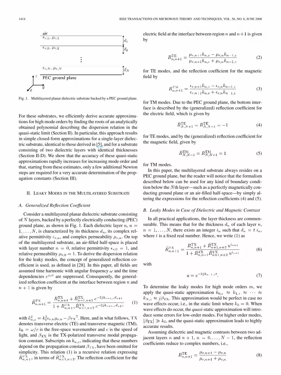
Fig. 1. Multilayered planar dielectric substrate backed by a PEC ground plane.
For these substrates, we efficiently derive accurate approxima-tions for high mode orders by finding the roots of an analyticallyobtained polynomial describing the dispersion relation in thequasi-static limit (Section II). In particular, this approach resultsin simple closed-form approximations for a single-layer dielec-tric substrate, identical to those derived in [5], and for a substrateconsisting of two dielectric layers with identical thicknesses(Section II-D). We show that the accuracy of these quasi-staticapproximations rapidly increases for increasing mode order andthat, starting from these estimates, only a few additional Newtonsteps are required for a very accurate determination of the prop-agation constants (Section III).
II. LEAKY MODES IN THE MULTILAYERED SUBSTRATE
A. Generalized Reflection Coefficient
Consider a multilayered planar dielectric substrate consistingof layers, backed by a perfectly electrically conducting (PEC)ground plane, as shown in Fig. 1. Each dielectric layer ,
, is characterized by its thickness , its complex rel-ative permittivity , and complex permeability . On topof the multilayered substrate, an air-filled half-space is placedwith layer number , relative permittivity , andrelative permeability . To derive the dispersion relationfor the leaky modes, the concept of generalized reflection co-efficient is used, as defined in [28]. In this paper, all fields areassumed time harmonic with angular frequency and the timedependencies are suppressed. Consequently, the general-ized reflection coefficient at the interface between region and
is given by
(1)
with . Here, and in what follows,denotes transverse electric (TE) and transverse magnetic (TM),
is the free-space wavenumber and is the speed oflight, and is the TX-polarized transverse modal propaga-tion constant. Subscripts on , indicating that these numbersdepend on the propagation constant , have been omitted forsimplicity. This relation (1) is a recursive relation expressing
in terms of . The reflection coefficient for the
electric field at the interface between region and is givenby
(2)
for TE modes, and the reflection coefficient for the magneticfield by
(3)
for TM modes. Due to the PEC ground plane, the bottom inter-face is described by the (generalized) reflection coefficient forthe electric field, which is given by
(4)
for TE modes, and by the (generalized) reflection coefficient forthe magnetic field, given by
(5)
for TM modes.In this paper, the multilayered substrate always resides on a
PEC ground plane, but the reader will notice that the formalismdescribed below can be used for any kind of boundary condi-tion below the th layer—such as a perfectly magnetically con-ducting ground plane or an air-filled half-space—by simply al-tering the expressions for the reflection coefficients (4) and (5).
B. Leaky Modes in Case of Dielectric and Magnetic Contrast
In all practical applications, the layer thickness are commen-surable. This means that for the thickness of each layer ,
, there exists an integer such that ,where is a fixed real number. Hence, we write (1) as
(6)
with
(7)
To determine the leaky modes for high mode orders , weapply the quasi-static approximation
. This approximation would be perfect in case nowave effects occur, i.e., in the static limit where . Whenwave effects do occur, the quasi-static approximation will intro-duce some errors for low-order modes. For higher order modes,
, and the quasi-static approximation leads to highlyaccurate results.
Assuming dielectric and magnetic contrasts between two ad-jacent layers and , , the reflectioncoefficients reduce to complex numbers, i.e.,
(8)
ROGIER AND GINSTE: FAST PROCEDURE TO ACCURATELY DETERMINE LEAKY MODES IN MULTILAYERED PLANAR DIELECTRIC SUBSTRATES 1415
for TE modes, and
(9)
for TM modes.We now proceed with the construction of the dispersion rela-
tion. Starting from the reflection coefficients at the bottom in-terface (4) and (5) and working our way up to the top layer bysuccessive application of (6) results in a reflection coefficient ofthe form
(10)
where and are polynomials of degree. The dispersion relation for the TX-polarized leaky
modes is given by . Hence, the leaky modes forhigh mode numbers may be found by finding the roots of thepolynomial . By applying an appropriate root-findingtechnique for polynomials, such as computing the eigenvaluesof the companion matrix or invoking fast polynomial root findertechniques [29], zeros , are found, after whichthe propagation constants of the leaky modes are determined by
(11)
It is clear that the above procedure applies when at least one ofthe reflection coefficients (8) for the TE modes or (9) for the TMmodes is different from zero.
C. Leaky Modes in Absence of Magnetic Contrast
In the absence of magnetic contrast, i.e., in case that all layershave relative permeability , , the re-flection coefficients (8) for the TE modes result in zero contri-butions for all layers, and hence, a more accurate approxima-tion for (2) is required. Using the second-order approximation
in the numerator of (2), thefirst-order quasi-static approximation in the de-nominator of (2), and given that , we obtain
(12)
for . These approximations are to be intro-duced into the polynomial equation expressing theTE-polarized dispersion relation. Construction of the reflectioncoefficient as described above [see (10)], leads to this polyno-mial , which is of the form
lower order terms (13)
or, by introducing (12),
lower order terms (14)
TABLE IMATERIAL PARAMETERS FOR THE SUBSTRATES CONSISTING
OF TWO DIELECTRIC LAYERS
We propose the following solution for the modal propagationconstants:
(15)
It is now shown a posteriori that (15) is a good choice and thatis indeed a constant, independent of the mode number .
Substitution of (15) into (7) leads to
(16)
where the constant remains to be determined. For the reflec-tion coefficients (12), we only retain the first two terms of thesolution proposed in (15), yielding
(17)
Introducing (16) and (17) into (13) results in
terms (18)
Since , we can neglect the terms of order forhigh mode orders , and (18) reduces to
(19)
yielding
(20)
and (15) becomes
(21)
A more accurate approximation is obtained by noting that, given(18), the lower order terms of order in (14) can beneglected for high mode orders , and (14) is rewritten as
(22)
1416 IEEE TRANSACTIONS ON MICROWAVE THEORY AND TECHNIQUES, VOL. 56, NO. 6, JUNE 2008
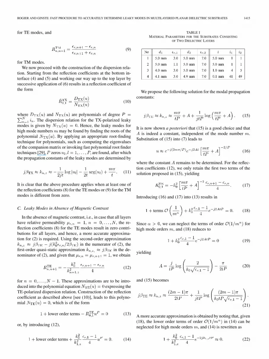
Fig. 2. Propagation constants � of the TM-polarized leaky modes of thenonmagnetic substrates 1 and 2 (Table I). Circles: quasi-static approximation.Crosses: exact locations. Plus signs: results obtained by using the techniquesdescribed in [22].
Fig. 3. Propagation constants � of the TM-polarized leaky modes of thenonmagnetic substrates 3 and 4 (Table I). Circles: quasi-static approximation.Crosses: exact locations. Plus signs: results obtained by using the techniquesdescribed in [22].
Closed-form solutions of this equation exist under the form ofLambert [30] functions
(23)
Fig. 4. Number of additional Newton steps required to obtain the propaga-tion constants � with ten digits of accuracy for the nonmagnetic substrate2 (Table I).
Fig. 5. Relative error on the estimated quasi-static propagation constants �of the nonmagnetic substrate 3 (Table I).
where each is integer and corresponds to a different branch ofthe Lambert function . Expression (22), with solution(23) is, in fact, an approximation that only takes the highestorder exponential into account. This approach correspondsto a multilayered medium with an effective refractive index
and total thickness , leading to an exponentialcontribution in (22), i.e., is replaced by .It can be readily seen—by successively applying the recursiverelationship (1) and by quasi-static approximation of —thatthe argument of this exponential can be approximated moreaccurately by
(24)
Solving the above (24) for yields
(25)
ROGIER AND GINSTE: FAST PROCEDURE TO ACCURATELY DETERMINE LEAKY MODES IN MULTILAYERED PLANAR DIELECTRIC SUBSTRATES 1417
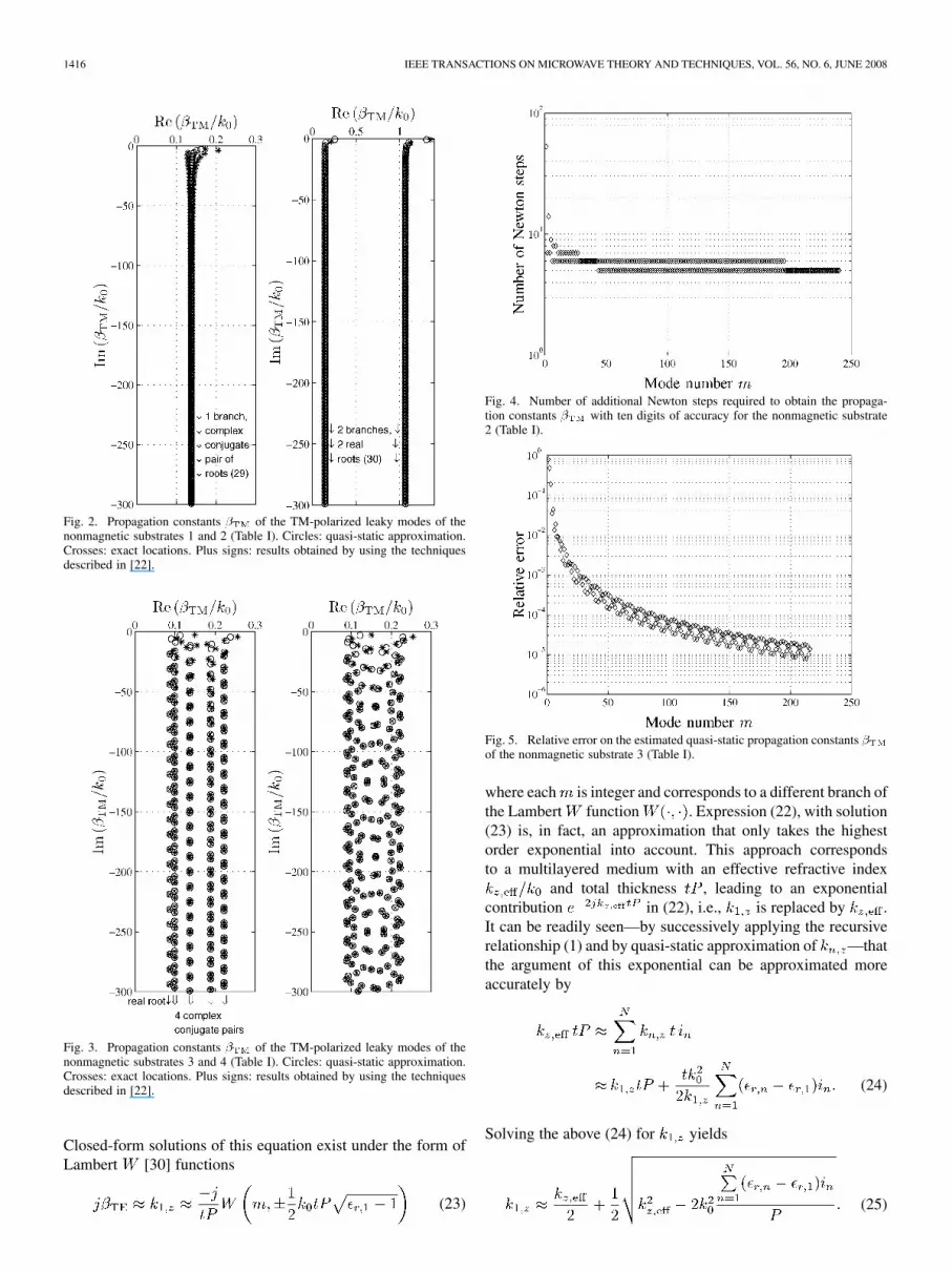
TABLE IICOMPARISON OF THE CPU TIMES FOR THE DETERMINATION OF THE TM-LEAKY WAVES OF THE NONMAGNETIC SUBSTRATES OF TABLE I
Substitution of , i.e., (23), into (25) results in abetter approximation for . If all layers have thesame dielectric constant, then we see from (25) that
,and this corresponds to the results obtained in [5] where theleaky modes were calculated for a single-layered substrate.
The reader notices that a similar procedure can be followed inthe case of magnetic contrast, but in absence of electric contrast
, .
D. Particular Cases
For the single-layered (microstrip) substrate backed by aperfectly conducting ground plane, the technique described inSection II-B corresponds to the results obtained in [5].
For the dielectric substrate consisting of two dielectric layersbacked by a perfectly conducting ground plane, the tech-nique described in Section II-B yields the dispersion relations
, i.e.,
(26)
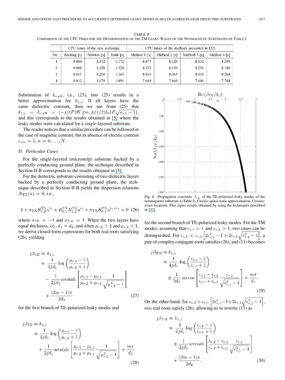
where and . When the two layers haveequal thickness, i.e., , and when and ,we derive closed-form expressions for both real roots satisfying(26), yielding
(27)
for the first branch of TE-polarized leaky modes and
(28)
Fig. 6. Propagation constants � of the TE-polarized leaky modes of thenonmagnetic substrate 4 (Table I). Circles: quasi-static approximation. Crosses:exact locations. Plus signs: results obtained by using the techniques describedin [22].
for the second branch of TE-polarized leaky modes. For the TMmodes, assuming that and , two cases can be
distinguished. For , apair of complex conjugate roots satisfies (26), and (11) becomes
(29)
On the other hand, for ,two real roots satisfy (26), allowing us to rewrite (11) as
(30)

1418 IEEE TRANSACTIONS ON MICROWAVE THEORY AND TECHNIQUES, VOL. 56, NO. 6, JUNE 2008
TABLE IIICOMPARISON OF THE CPU TIMES FOR THE DETERMINATION OF THE TE-LEAKY WAVES OF THE NONMAGNETIC SUBSTRATE 4 OF TABLE I
III. EXAMPLES
The above proposed technique is now extensively testedby means of several numerical examples. The accuracy ofthe method is validated and its computational efficiency isdemonstrated by comparing the new approach with the numer-ical techniques proposed in [22]. Emphasis is on showing thereader that the proposed procedure is indeed suited for a largevariety of multilayered substrates. We focus on nonmagneticsubstrates ( ) since these are the most currently used inplanar microwave circuits. All calculations were carried out inMathematica 6.0 on a Pentium T7400 Centrino Duo 2.16-GHzmachine with 2-GB RAM.
First, consider a substrate consisting of two dielectric layers.In order to investigate the different approximations proposedin Section II, four different scenarios are considered, with thelayer parameters for each scenario specified in Table I. The foursubstrates are all assumed to be nonmagnetic (
). The angular frequency is fixed to Hz.In Figs. 2 and 3, the location of the propagation constants
of the TM-polarized leaky modes are shown in the complex-plane for the first two substrates and second two substrates,
respectively. The quasi-static solutions, shown by the circlesin Figs. 2 and 3, are calculated based on (29) for substrate 1,leading to a single branch of zeros resulting from a complex con-jugate pair of roots satisfying (26). For substrate 2, (30) leads totwo branches of zeros resulting from two real roots satisfying(26). For substrates 3 and 4, the roots of the polynomialsof orders and , respectively, are determined andcombined with (11). The exact locations of the roots (crosses onFig. 3) are determined by performing extra Newton iterations(see e.g., [31])
(31)
starting from the quasi-static estimates. They coincide withleaky modes obtained with the root-finding techniques de-scribed in [22] (plus signs on Fig. 3). Observe that for substrate3, one branch of leaky modes corresponds to the real zero andfour branches result from the four complex conjugate pairs ofroots satisfying the polynomial of order .
Fig. 4 shows the number of additional Newton steps requiredfor substrate 2 to obtain propagation constants with tendigits of accuracy (crosses on Figs. 2 and 3), as a function ofmode order, where the zeros were ordered in descending orderbased on their imaginary part. Similar results are obtained forthe other substrates. In order to reach ten digits of accuracystarting from the quasi-static estimate, at most ten extra Newtonsteps are required when the mode order is larger than 3 for all
Fig. 7. Number of additional Newton steps required to obtain the propaga-tion constants � with ten digits of accuracy for the nonmagnetic substrate4 (Table I).
Fig. 8. Relative error on the estimated quasi-static propagation constants �of the nonmagnetic substrate 4 (Table I).
substrates. When the mode order exceeds 21 for substrate 1, 27for substrate 2, 23 for substrate 3, and 20 for substrate 4, tendigits of accuracy are obtained after, at most, six extra Newtonsteps.
Fig. 5 demonstrates the relative accuracy of the estimatedquasi-static propagation constants obtained for substrate 3.Similar results hold for the other substrates: for all estimates, atleast three digits of accuracy are obtained starting from modeorder 26 for substrates 1 and 3, 44 for substrate 2, and 28 forsubstrate 4. The estimates provide an accuracy up to four digitsstarting from zero number 82 for substrate 1, 142 for substrate2, and 87 for substrates 3 and 4. A robust process to determineall relevant propagation constants of the leaky and propagation

ROGIER AND GINSTE: FAST PROCEDURE TO ACCURATELY DETERMINE LEAKY MODES IN MULTILAYERED PLANAR DIELECTRIC SUBSTRATES 1419
TABLE IVRELATIVE ACCURACY OF THE QUASI-STATIC APPROXIMATIONS (23) AND THE CORRECTED ESTIMATES (25) FOR ALL FOUR SUBSTRATES OF TABLE I
TABLE VMATERIAL PARAMETERS FOR THE SUBSTRATES CONSISTING OF THREE DIELECTRIC LAYERS. (�) THE THIRD SUBSTRATE CONSISTS
OF THREE LAYERS OF DUROID, i.e., FROM BOTTOM TO TOP: RT/DUROID 5870, RT/DUROID 6006,AND RT/DUROID 6010 LM. THE UNIT “mil” CORRESPONDS TO ONE-THOUSANDTH
OF AN INCH, VIZ. 0.0254 mm, AND IS OFTEN USED FOR THIN SUBSTRATES
modes proceeds by combining the Newton procedure based onquasi-static estimates with a robust numerical technique [22] todetermine the zeros only in that area of the fourth quadrant ofthe complex plane where the normalized imaginary part is largerthan, say, 5.
In Table II, the efficiency of the proposed method is evalu-ated by comparing the CPU timings of several methods. Therooting of the polynomials happens very fast; determining thezeros of the polynomial of order takes less than1 s. For each substrate, the Newton process takes less than 1.4 sto converge to ten digits of accuracy for all propagation con-stants with a normalized imaginary part larger than 300. Forcomparison, the four optimized numerical techniques to deter-mine zeros of the dispersion relation in the complex plane, i.e.,the pencil-of-function method, the singular-value-decomposi-tion rank-based method, the Prony–Burrus–Parks method, andthe Neville-type interpolation proposed in [22], all require morethan 7.5 s to determine all propagation constants with a normal-ized imaginary part larger than 300, and again with ten digitsof accuracy. Moreover, a straightforward, but very robust im-plementation of the principal of the argument method requires1 min 44 s to find all zeros in that same region (this straightfor-ward method is not indicated in Table II).
Second, we turn our attention to the TE-polarized leakymodes for the nonmagnetic substrates specified in Table I.Due to the absence of magnetic contrast, we revert to thequasi-static approximation (23) for the TE-polarized leakymodes of all four substrates. To demonstrate the accuracy of(23), let us just study one substrate into detail, say, substrate4 in Table I. For this substrate, Fig. 6 demonstrates that thequasi-static solutions based on (23), shown by the circles, agreewell with the exact location of the propagation constants ,shown by means of crosses. These exact locations are againdetermined by performing additional Newton steps startingfrom the quasi-static estimates. Also on Fig. 6, the resultsobtained with the techniques described in [22] are indicatedwith plus signs.
Again, in Table III, the efficiency of the proposed method isevaluated. The rooting of the polynomial of ordertakes less than 1 s. The Newton process takes less than 1.4 s toconverge to ten digits of accuracy for all propagation constantswith a normalized imaginary part larger than 300, and hence,also even for the low-order modes with an imaginary part largerthan 5. For comparison, the four optimized numerical tech-niques to determine zeros of the dispersion relation in the com-plex plane proposed in [22] all require more than 7.5 s to de-termine all propagation constants with a normalized imaginarypart larger than 300, and again with ten digits of accuracy.
Furthermore, Fig. 7 clearly shows that starting from thecorrected estimates (25), the Newton process for obtainingpropagation constants with ten digits of accuracy consis-tently results in less Newton steps (shown via crosses in Fig. 7)than using the quasi-static approximation (23) as starting values(shown via diamonds in Fig. 7). Indeed, the corrected estimates(25) yield a higher relative accuracy than the quasi-staticapproximation (23) (Fig. 8).
Considering all four substrates, Table IV demonstrates the ac-curacy that is obtained using the estimates based on (23) and(25). Again it is immediately clear that the corrected estimates(25) yield a higher relative accuracy than the quasi-static ap-proximations (23). As expected, for increasing mode order, therelative accuracy also increases. This fast approach must onlybe completed by elaborate root finding in a limited portion ofthe fourth quadrant, i.e., where the normalized imaginary partis larger than, say, 5.
Finally, consider a substrate consisting of three dielectriclayers. Three different scenarios are considered, with the layerparameters for each scenario specified in Table V. The angularfrequency is fixed to Hz. The three substrates areassumed to be nonmagnetic. In Figs. 9 and 10, the location ofthe propagation constants of the TM-polarized leaky modes areshown in the complex -plane for the first two substrates andthird substrate, respectively. The quasi-static solutions, shownby the circles in Figs. 9 and 10, are all calculated by finding

1420 IEEE TRANSACTIONS ON MICROWAVE THEORY AND TECHNIQUES, VOL. 56, NO. 6, JUNE 2008
Fig. 9. Propagation constants � of the TM-polarized leaky modes of thenonmagnetic multilayered substrates 1 and 2 (Table V). Circles: quasi-static ap-proximation. Crosses: exact locations. Plus signs: results obtained by using thetechniques described in [22].
the roots of the polynomials of ordersand combined with (11) for substrates 1–3, respectively.The exact locations of the roots (crosses on Figs. 9 and 10)are determined by performing extra Newton iterations startingfrom the quasi-static estimates. They coincide with leakymodes obtained with the root-finding techniques described in[22] (plus signs on Figs. 9 and 10).
In Table VI, the efficiency of the proposed method is demon-strated by comparing the CPU timings. The rooting of the poly-nomial of order for substrate 2 takes less than2 s. The Newton process takes less than 3.2 s to converge to tendigits of accuracy for all propagation constants with a normal-ized imaginary part larger than 300, and hence, also even forthe low-order modes with an imaginary part larger than 5. Forcomparison, the four optimized numerical techniques to deter-mine zeros of the dispersion relation in the complex plane pro-posed in [22] for substrates 1 and 2 require approximately 15 sto determine all propagation constants with a normalized imag-inary part larger than 300, and again with ten digits of accu-racy, and require approximately 8 s to determine all propagationconstants of substrate 3 with a normalized imaginary part largerthan 300, and again with ten digits of accuracy. Of course,the CPU times for substrate 3 are smaller than for substrates 1and 2 because, for the thinner Duroid substrate, less modes arepresent with an imaginary part larger than 300. This is causedby the fact that the spacing between the modes increases withdecreasing substrate thickness.
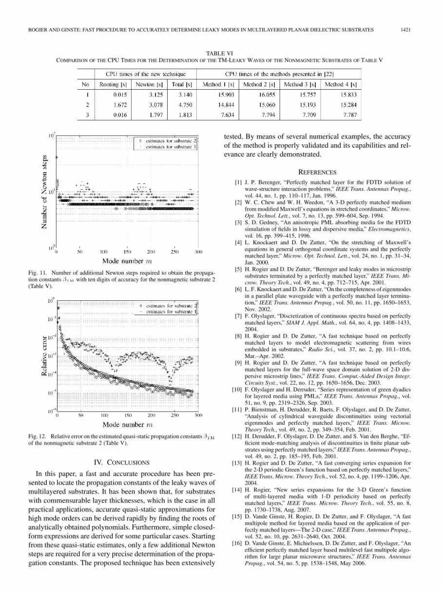
The number of additional Newton steps, required to deter-mine the exact location of the propagation constants withten digits of accuracy (dots in Figs. 9 and 10), are shown inFig. 11 for substrate 2 and as a function of mode order. Two
Fig. 10. Propagation constants � of the TM-polarized leaky modes of thenonmagnetic multilayered substrate 3 and 4 (Table V). Circles: quasi-static ap-proximation. Crosses: exact locations. Plus signs: results obtained by using thetechniques described in [22].
starting values for the Newton process are considered, the onesbased on the zeros of the polynomial of order , as wellas the starting values for substrate 1, resulting from the zerosof the polynomial of order . We notice that simpli-fying the ratio between the layer thicknesses for keeping thepolynomial order low still allows to determine the zeros withhigh accuracy, albeit by performing some extra Newton steps.Indeed, for mode orders larger than 3, the Newton process con-verges in, at most, 15 iterations starting from the estimates forsubstrate 1. This should be compared with the results for theNewton process starting from the quasi-static estimates of thegeometrically correct configuration. In order to reach ten digitsof accuracy starting from the quasi-static estimate, at most, tenextra Newton steps are required when the mode order is largerthan 4 for substrates 1 and 2. When the mode order exceeds 31for substrate 1 and 30 for substrate 2, ten digits of accuracy areobtained after, at most, six extra Newton steps. Fig. 12 demon-strates the relative accuracy of the estimated quasi-static propa-gation constants obtained for substrate 2.
The above examples demonstrate that the proposed techniqueis very efficient and accurate. Of course, the method is bestsuited to locate high-order modes since the accuracy of thequasi-static approximations is the best for high mode orders.The location of low-order modes, with an imaginary part thatis larger than, say, 5, can be found easily with the techniquesdescribed in [22]. When used in a PML-based formalism, thenew method is especially advantageous since the propagationconstants of many modes need to be accurately determinedand also because the method remains stable for high modeorders.
ROGIER AND GINSTE: FAST PROCEDURE TO ACCURATELY DETERMINE LEAKY MODES IN MULTILAYERED PLANAR DIELECTRIC SUBSTRATES 1421
TABLE VICOMPARISON OF THE CPU TIMES FOR THE DETERMINATION OF THE TM-LEAKY WAVES OF THE NONMAGNETIC SUBSTRATES OF TABLE V
Fig. 11. Number of additional Newton steps required to obtain the propaga-tion constants � with ten digits of accuracy for the nonmagnetic substrate 2(Table V).
Fig. 12. Relative error on the estimated quasi-static propagation constants �of the nonmagnetic substrate 2 (Table V).
IV. CONCLUSIONS
In this paper, a fast and accurate procedure has been pre-sented to locate the propagation constants of the leaky waves ofmultilayered substrates. It has been shown that, for substrateswith commensurable layer thicknesses, which is the case in allpractical applications, accurate quasi-static approximations forhigh mode orders can be derived rapidly by finding the roots ofanalytically obtained polynomials. Furthermore, simple closed-form expressions are derived for some particular cases. Startingfrom these quasi-static estimates, only a few additional Newtonsteps are required for a very precise determination of the propa-gation constants. The proposed technique has been extensively
tested. By means of several numerical examples, the accuracyof the method is properly validated and its capabilities and rel-evance are clearly demonstrated.
REFERENCES
[1] J. P. Berenger, “Perfectly matched layer for the FDTD solution ofwave-structure interaction problems,” IEEE Trans. Antennas Propag.,vol. 44, no. 1, pp. 110–117, Jan. 1996.
[2] W. C. Chew and W. H. Weedon, “A 3-D perfectly matched mediumfrom modified Maxwell’s equations in stretched coordinates,” Microw.Opt. Technol. Lett., vol. 7, no. 13, pp. 599–604, Sep. 1994.
[3] S. D. Gedney, “An anisotropic PML absorbing media for the FDTDsimulation of fields in lossy and dispersive media,” Electromagnetics,vol. 16, pp. 399–415, 1996.
[4] L. Knockaert and D. De Zutter, “On the stretching of Maxwell’sequations in general orthogonal coordinate systems and the perfectlymatched layer,” Microw. Opt. Technol. Lett., vol. 24, no. 1, pp. 31–34,Jan. 2000.
[5] H. Rogier and D. De Zutter, “Berenger and leaky modes in microstripsubstrates terminated by a perfectly matched layer,” IEEE Trans. Mi-crow. Theory Tech., vol. 49, no. 4, pp. 712–715, Apr. 2001.
[6] L. F. Knockaert and D. De Zutter, “On the completeness of eigenmodesin a parallel plate waveguide with a perfectly matched layer termina-tion,” IEEE Trans. Antennas Propag., vol. 50, no. 11, pp. 1650–1653,Nov. 2002.
[7] F. Olyslager, “Discretization of continuous spectra based on perfectlymatched layers,” SIAM J. Appl. Math., vol. 64, no. 4, pp. 1408–1433,2004.
[8] H. Rogier and D. De Zutter, “A fast technique based on perfectlymatched layers to model electromagnetic scattering from wiresembedded in substrates,” Radio Sci., vol. 37, no. 2, pp. 10.1–10.6,Mar.–Apr. 2002.
[9] H. Rogier and D. De Zutter, “A fast technique based on perfectlymatched layers for the full-wave space domain solution of 2-D dis-persive microstrip lines,” IEEE Trans. Comput.-Aided Design Integr.Circuits Syst., vol. 22, no. 12, pp. 1650–1656, Dec. 2003.
[10] F. Olyslager and H. Derruder, “Series representation of green dyadicsfor layered media using PMLs,” IEEE Trans. Antennas Propag., vol.51, no. 9, pp. 2319–2326, Sep. 2003.
[11] P. Bienstman, H. Derudder, R. Baets, F. Olyslager, and D. De Zutter,“Analysis of cylindrical waveguide discontinuities using vectorialeigenmodes and perfectly matched layers,” IEEE Trans. Microw.Theory Tech., vol. 49, no. 2, pp. 349–354, Feb. 2001.
[12] H. Derudder, F. Olyslager, D. De Zutter, and S. Van den Berghe, “Ef-ficient mode-matching analysis of discontinuities in finite planar sub-strates using perfectly matched layers,” IEEE Trans. Antennas Propag.,vol. 49, no. 2, pp. 185–195, Feb. 2001.
[13] H. Rogier and D. De Zutter, “A fast converging series expansion forthe 2-D periodic Green’s function based on perfectly matched layers,”IEEE Trans. Microw. Theory Tech., vol. 52, no. 4, pp. 1199–1206, Apr.2004.
[14] H. Rogier, “New series expansions for the 3-D Green’s functionof multi-layered media with 1-D periodicity based on perfectlymatched layers,” IEEE Trans. Microw. Theory Tech., vol. 55, no. 8,pp. 1730–1738, Aug. 2007.
[15] D. Vande Ginste, H. Rogier, D. De Zutter, and F. Olyslager, “A fastmultipole method for layered media based on the application of per-fectly matched layers—The 2-D case,” IEEE Trans. Antennas Propag.,vol. 52, no. 10, pp. 2631–2640, Oct. 2004.
[16] D. Vande Ginste, E. Michielssen, D. De Zutter, and F. Olyslager, “Anefficient perfectly matched layer based multilevel fast multipole algo-rithm for large planar microwave structures,” IEEE Trans. AntennasPropag., vol. 54, no. 5, pp. 1538–1548, May 2006.

1422 IEEE TRANSACTIONS ON MICROWAVE THEORY AND TECHNIQUES, VOL. 56, NO. 6, JUNE 2008
[17] D. Yevick and D. J. Thomson, “Impedance-matched absorbers for fi-nite-difference parabolic equation algorithms,” J. Acoust. Soc. Amer.,vol. 107, no. 3, pp. 1226–1234, 2000.
[18] H. Rogier and D. De Zutter, “Convergence behavior and acceleration ofthe Berenger and leaky modes series composing the 2-D Green’s func-tion for the microstrip substrate,” IEEE Trans. Microw. Theory Tech.,vol. 50, no. 7, pp. 1696–1704, Jul. 2002.
[19] J. Zhu and Y. Y. Lu, “Leaky modes of slab waveguides—Asymptoticsolutions,” J. Lightw. Technol., vol. 25, no. 3, pp. 1619–1623, Mar.2006.
[20] J. Zhu, Z. Chena, and S. Tang, “Leaky modes of optical waveguideswith varied refractive index for microchip optical interconnect appli-cations—Asymptotic solutions,” Microelectron. Reliab., vol. 48, no. 4,pp. 555–562, Apr. 2007.
[21] J. X. Zhu and Y. Y. Lu, “Asymptotic solutions of the leaky modes andPML modes in a Pekeris waveguide,” Wave Motion, vol. 45, no. 3, pp.207–216, Jan. 2008.
[22] L. Knockaert and H. Rogier, “An FFT-based signal identification ap-proach for obtaining the propagation constants of the leaky modes inlayered media,” Int. J. Electron. Commun., vol. 59, no. 4, pp. 230–238,Jun. 2005.
[23] M. Marin, S. Barkeshli, and P. H. Pathak, “Efficient analysis of planarmicrostrip geometries using a closed-form asymptotic representationof the grounded dielectric slab Green’s function,” IEEE Trans. Microw.Theory Tech., vol. 37, no. 4, pp. 669–679, Apr. 1989.
[24] P. Baccarelli, P. Burghignoli, F. Frezza, A. Galli, G. Lovat, and D.R. Jackson, “Uniform analytical representation of the continuousspectrum excited by dipole sources in a multilayer dielectric structurethrough weighted cylindrical leaky waves,” IEEE Trans. AntennasPropag., vol. 52, no. 3, pp. 653–665, Mar. 2004.
[25] C. G. Hsu, R. F. Harrington, J. R. Mautz, and T. K. Sarkar, “On the lo-cation of leaky wave poles for a grounded dielectric slab,” IEEE Trans.Microw. Theory Tech., vol. 39, no. 2, pp. 346–349, Feb. 1991.
[26] M. A. Marin, S. Barkeshli, and P. H. Pathak, “On the location of properand improper surface wave poles for the grounded dielectric slab,”IEEE Trans. Antennas Propag., vol. 38, no. 4, pp. 570–573, Apr. 1990.
[27] H. Rogier, L. Knockaert, and D. De Zutter, “Fast calculation of thepropagation constants of leaky and Berenger modes of planar and cir-cular dielectric waveguides terminated by a perfectly matched layer,”Microw. Opt. Technol. Lett., vol. 37, no. 3, pp. 167–171, May 2003.
[28] W. C. Chew, Waves and Fields in Inhomogeneous Media. New York:Van Nostrand, 1990.
[29] G. A. Sitton, C. S. Burrus, J. W. Fox, and S. Treite, “Factoring very-high-degree polynomials,” IEEE Signal Process. Mag., vol. 20, no. 6,pp. 27–42, Nov. 2003.
[30] R. M. Corless, G. H. Gonnet, D. E. G. Hare, D. J. Jeffrey, and D. E.Knuth, “On the Lambert� function,” Adv. Comput. Math., vol. 5, no.4, pp. 329–359, 1996.
[31] L. Yau and A. Ben-Israel, “The Newton and Halley methods for com-plex roots,” Amer. Math. Monthly, vol. 105, no. 9, pp. 806–818, Nov.1998.
Hendrik Rogier (S’96–A’99–M’00–SM’06) wasborn in 1971. He received the Electrical Engineeringand Ph.D. degrees from Ghent University, Gent,Belgium, in 1994 and in 1999, respectively.
He is currently a Post-Doctoral Research Fellow ofthe Fund for Scientific Research-Flanders (FWO-V),Department of Information Technology, GhentUniversity, where he is also a Part-Time Professorwith the Department of Information Technology.From October 2003 to April 2004, he was a Vis-iting Scientist with the Mobile Communications
Group, Vienna University of Technology. He has authored or coauthoredapproximately 40 papers in international journals and approximately 55 papersin conference proceedings. His current research interests are the analysisof electromagnetic (EM) waveguides, EM simulation techniques applied toelectromagnetic compatibility (EMC), and signal integrity problems, as wellas to indoor propagation and antenna design, and in smart antenna systems forwireless networks.
Dr. Rogier was a two-time recipient of the URSI Young Scientist Award pre-sented at the 2001 URSI Symposium on Electromagnetic Theory and at the 2002URSI General Assembly.
Dries Vande Ginste (A’07–M’07) was born in 1977.He received the M.S. degree and Ph.D. degree inelectrotechnical engineering from Ghent University,Gent, Belgium, in 2000 and 2005, respectively.
From October 2000 to March 2006, he was withthe Department of Information Technology (INTEC),Ghent University, as a Doctoral and Post-DoctoralResearcher, where his research focused on fast tech-niques for the modeling of layered media. In Juneand July 2004, he was a Visiting Scientist with theDepartment of Electrical and Computer Engineering,
University of Illinois at Urbana-Champaign (UIUC). From April 2006 to May2007, he was a Senior Consultant with Applied Logistics, where he was mainlyinvolved in feasibility studies and technical-economical evaluations for clients,and where he also had commercial responsibilities. In June 2007, he rejoined theDepartment of Information Technology, INTEC, as a Technology Developer in-volved in the field of high-frequency technologies and applications. His currentresearch interests include computational electromagnetics (CEM), antenna de-sign, electromagnetic compatibility (EMC), and signal integrity issues.
Related Documents