A failure study of housing of the gearboxes of series 2600 locomotives of the Portuguese Railway Company T.L.M. Morgado a, * , C.M. Branco b , V. Infante b a Department of Mechanical Engineering, Escola Superior de Tecnologia de Abrantes, Instituto Polite ´cnico de Tomar, Rua 17 de Agosto de 1808, 2200 Abrantes, Portugal b Department of Mechanical Engineering, Instituto Superior Te ´ cnico Av. Rovisco Pais, 1096 Lisboa Codex, Portugal Received 21 July 2006; accepted 20 November 2006 Available online 22 January 2007 Abstract This paper presents the results obtained in the study of the cracking problems on the driving gearboxes of series 2600 locomotives. These components were under big vibration and severe fatigue conditions. The cracks in these components appear in two distinct parts: in the upper zone of the cover and in the frontal central zone of the body of the housing. The loading data was obtained in service, in two routine journeys: Lisboa–Porto intercity train, with maximum speed of 160 km/h and Entroncamento–Guarda freight train, with a maximum speed of 120 km/h. Finally from a synthesis of all the data obtained a set of conclusions are presented to prevent further failures in the driving gearboxes. Ó 2006 Published by Elsevier Ltd. Keywords: Failure study; Housing of railway gearboxes; Fatigue analysis; Cracking problems; St22-3 1. Introduction Trains are complex machines, with many critical components. Structural design of the trains is based on the design standards, the function of the structure and the environmental conditions. The service condition includes the forces, vibration, environment, etc. For the design, strength analysis and testing of the structure, the service condition has to be taken into account. The simulated external loads for the strength analysis and testing of the structure are determined according to its practical service conditions [1,2]. Failure analysis in cast steel railway coupling of the freight trains (coal transportation) line has been con- ducted by the authors [3], where strain gauge data were analyzed and from those data fatigue cycles were derived. Calculation of the damage factors in several zones of the coupling and for the different stages of the journey and loading conditions were made. And the stress concentration factors were calculated from the computed stress distribution and for the critical areas of the coupling. 1350-6307/$ - see front matter Ó 2006 Published by Elsevier Ltd. doi:10.1016/j.engfailanal.2006.11.052 * Corresponding author. E-mail addresses: [email protected] (T.L.M. Morgado), [email protected] (C.M. Branco), [email protected] (V. Infante). www.elsevier.com/locate/engfailanal Engineering Failure Analysis 15 (2008) 154–164

Welcome message from author
This document is posted to help you gain knowledge. Please leave a comment to let me know what you think about it! Share it to your friends and learn new things together.
Transcript

www.elsevier.com/locate/engfailanal
Engineering Failure Analysis 15 (2008) 154–164
A failure study of housing of the gearboxes of series2600 locomotives of the Portuguese Railway Company
T.L.M. Morgado a,*, C.M. Branco b, V. Infante b
a Department of Mechanical Engineering, Escola Superior de Tecnologia de Abrantes, Instituto Politecnico de Tomar,
Rua 17 de Agosto de 1808, 2200 Abrantes, Portugalb Department of Mechanical Engineering, Instituto Superior Tecnico Av. Rovisco Pais, 1096 Lisboa Codex, Portugal
Received 21 July 2006; accepted 20 November 2006Available online 22 January 2007
Abstract
This paper presents the results obtained in the study of the cracking problems on the driving gearboxes of series 2600locomotives. These components were under big vibration and severe fatigue conditions. The cracks in these componentsappear in two distinct parts: in the upper zone of the cover and in the frontal central zone of the body of the housing. Theloading data was obtained in service, in two routine journeys: Lisboa–Porto intercity train, with maximum speed of160 km/h and Entroncamento–Guarda freight train, with a maximum speed of 120 km/h. Finally from a synthesis ofall the data obtained a set of conclusions are presented to prevent further failures in the driving gearboxes.� 2006 Published by Elsevier Ltd.
Keywords: Failure study; Housing of railway gearboxes; Fatigue analysis; Cracking problems; St22-3
1. Introduction
Trains are complex machines, with many critical components. Structural design of the trains is based on thedesign standards, the function of the structure and the environmental conditions. The service conditionincludes the forces, vibration, environment, etc. For the design, strength analysis and testing of the structure,the service condition has to be taken into account. The simulated external loads for the strength analysis andtesting of the structure are determined according to its practical service conditions [1,2].
Failure analysis in cast steel railway coupling of the freight trains (coal transportation) line has been con-ducted by the authors [3], where strain gauge data were analyzed and from those data fatigue cycles werederived. Calculation of the damage factors in several zones of the coupling and for the different stages ofthe journey and loading conditions were made. And the stress concentration factors were calculated fromthe computed stress distribution and for the critical areas of the coupling.
1350-6307/$ - see front matter � 2006 Published by Elsevier Ltd.
doi:10.1016/j.engfailanal.2006.11.052
* Corresponding author.E-mail addresses: [email protected] (T.L.M. Morgado), [email protected] (C.M. Branco), [email protected] (V. Infante).

Fig. 1. Gearbox connected with the motor.
T.L.M. Morgado et al. / Engineering Failure Analysis 15 (2008) 154–164 155
Housings of railway vehicle gearboxes are examples of components which are subjected to complex stressesduring operation. Stresses are mainly generated by mass forces transmitted from motor via the flanged con-nection to the housing neck (Fig. 1) and also by loading resulting from lateral drive and starting and brakingoperations. Moreover, the loads acting on gear wheels generate bearing forces which must be taken up by thegearbox housing, [4,5].
A significant number of failures have occurred in housings of railway vehicle gearboxes which led to greatlosses and disruption of service. The cracks appear to be fatigue cracks due to dynamic loads produced in theload wagons of freight trains or of the passenger trains. In this study, attention is devoted to analysis of thedamage of the housing gearboxes subjected to both operational and overspeed conditions and also to indicatecritical areas from the point of view of the stress analysis. The additional goal of this analysis is to improve thesafety and the reliability of these components.
In this paper, measurement procedure of the displacements in service and results are presented. For theaccomplishment of this work the following tasks were made:
� Evaluation of the mechanical characteristics of the steels of the two different parts of the driving gearboxes(cover and body), and determination of the elasticity modulus of the steels.� Measurement of the extensions in service of the housing (cover and body) of the box, using electric strain
gauge/rosette type, bonded in critical zones, where the cracks were detected.� Calculation of the stresses in the most highly requested supports of the driving gearbox.� Forecast of the fatigue damages at critical locations.� Final conclusions.
2. Material characterization of the housing of the gearbox
The housing of the driving gearbox is of welded construction; the body of the box is a structural steel of lowcarbon, with 8 mm thickness, according to ARMCO (St22-3) specification. The steel of the cover is St37-2DIN specification. In Table 1 are indicated the chemical compositions in weight of these two steels, obtainedin removed samples of one of the housings. The data showed in Table 1 gives a lower carbon content in thebody of the housing, but for the cover of the housing there is a higher amount of alloy elements. Therefore thisgives an increase in the carbon equivalent (0.26% for body and 0.20% for the cover).
Vickers hardness was obtained also for the two parts of the housing. In this procedure a load of 5 Kgf wasapplied during 15 s in polished steel samples. The equipment used was a digital macro hardness machine. Tenindentations were made. The results were following:
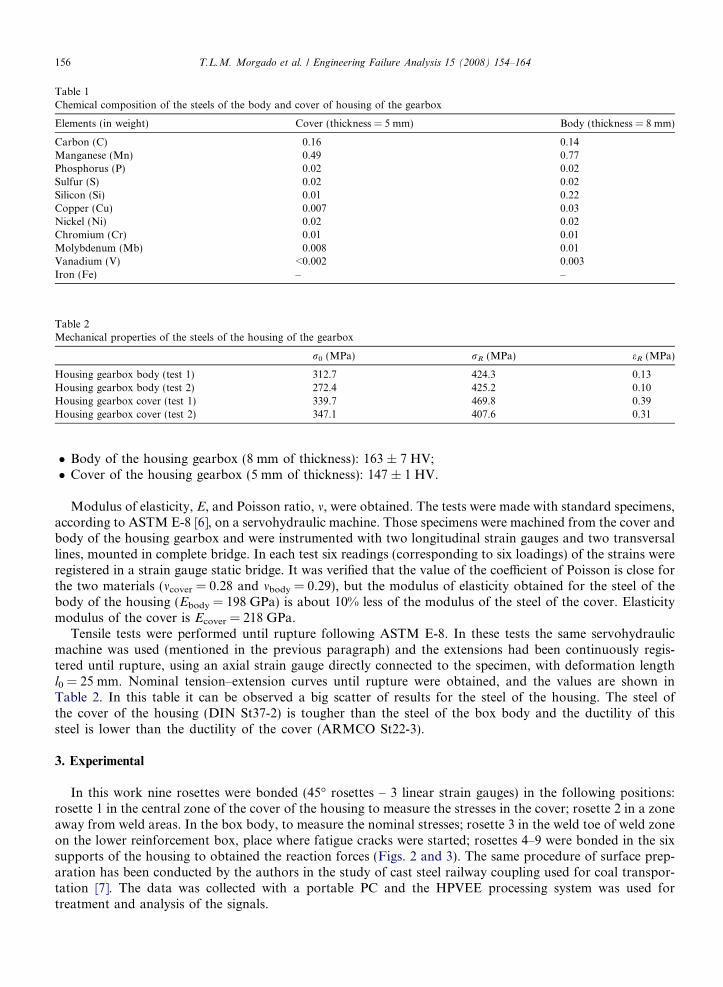
Table 1Chemical composition of the steels of the body and cover of housing of the gearbox
Elements (in weight) Cover (thickness = 5 mm) Body (thickness = 8 mm)
Carbon (C) 0.16 0.14Manganese (Mn) 0.49 0.77Phosphorus (P) 0.02 0.02Sulfur (S) 0.02 0.02Silicon (Si) 0.01 0.22Copper (Cu) 0.007 0.03Nickel (Ni) 0.02 0.02Chromium (Cr) 0.01 0.01Molybdenum (Mb) 0.008 0.01Vanadium (V) <0.002 0.003Iron (Fe) – –
Table 2Mechanical properties of the steels of the housing of the gearbox
r0 (MPa) rR (MPa) eR (MPa)
Housing gearbox body (test 1) 312.7 424.3 0.13Housing gearbox body (test 2) 272.4 425.2 0.10Housing gearbox cover (test 1) 339.7 469.8 0.39Housing gearbox cover (test 2) 347.1 407.6 0.31
156 T.L.M. Morgado et al. / Engineering Failure Analysis 15 (2008) 154–164
� Body of the housing gearbox (8 mm of thickness): 163 ± 7 HV;� Cover of the housing gearbox (5 mm of thickness): 147 ± 1 HV.
Modulus of elasticity, E, and Poisson ratio, m, were obtained. The tests were made with standard specimens,according to ASTM E-8 [6], on a servohydraulic machine. Those specimens were machined from the cover andbody of the housing gearbox and were instrumented with two longitudinal strain gauges and two transversallines, mounted in complete bridge. In each test six readings (corresponding to six loadings) of the strains wereregistered in a strain gauge static bridge. It was verified that the value of the coefficient of Poisson is close forthe two materials (mcover = 0.28 and mbody = 0.29), but the modulus of elasticity obtained for the steel of thebody of the housing (Ebody = 198 GPa) is about 10% less of the modulus of the steel of the cover. Elasticitymodulus of the cover is Ecover = 218 GPa.
Tensile tests were performed until rupture following ASTM E-8. In these tests the same servohydraulicmachine was used (mentioned in the previous paragraph) and the extensions had been continuously regis-tered until rupture, using an axial strain gauge directly connected to the specimen, with deformation lengthl0 = 25 mm. Nominal tension–extension curves until rupture were obtained, and the values are shown inTable 2. In this table it can be observed a big scatter of results for the steel of the housing. The steel ofthe cover of the housing (DIN St37-2) is tougher than the steel of the box body and the ductility of thissteel is lower than the ductility of the cover (ARMCO St22-3).
3. Experimental
In this work nine rosettes were bonded (45� rosettes – 3 linear strain gauges) in the following positions:rosette 1 in the central zone of the cover of the housing to measure the stresses in the cover; rosette 2 in a zoneaway from weld areas. In the box body, to measure the nominal stresses; rosette 3 in the weld toe of weld zoneon the lower reinforcement box, place where fatigue cracks were started; rosettes 4–9 were bonded in the sixsupports of the housing to obtained the reaction forces (Figs. 2 and 3). The same procedure of surface prep-aration has been conducted by the authors in the study of cast steel railway coupling used for coal transpor-tation [7]. The data was collected with a portable PC and the HPVEE processing system was used fortreatment and analysis of the signals.

Fig. 2. Identification of the strain gauges on the housing gearbox (motor side).
Fig. 3. Identification of the strain gauge on the gearbox outside side.
T.L.M. Morgado et al. / Engineering Failure Analysis 15 (2008) 154–164 157
The data was obtained in service, in the Lisbon–Porto Intercity passengers train, with a maximum speed of160 km/h and in the Entroncamento–Guarda freight train, with a maximum speed of 120 km/h (Table 3). Theprogram of the rosettes readings were made in order to get the best possible comparative information. Thosestages are the critical section of the journey, in what concerns speed, power and track oscillations.
For the Lisbon–Porto journey in the Intercity, the following 6 stages were selected:
� Entroncamento–Fatima: Acquisition time – 894 s; Number of km – 23.3 km;� Fatima–Pombal: Acquisition time – 1180 s; Number of km – 40 km;� Pombal–Alfarelos: Acquisition time – 1037 s; Number of km – 29 km;� Alfarelos–CoimbraB: Acquisition time – 900 s; Number of km – 18.7 km;

Table 3Entroncamento–Guarda freight train. Plan of the readings
Rosettes id. FirstreadingMortigua(73.5 km)(78.5 km)
Secondreading(84 km)
Third readingStaCombaDao(85.5 km)Castelejo(89.7 km)
FourthreadingCastelejo(89.7 km)Oliverinha(102.4 km)
FifthreadingOliverinha(102.4 km)Nelas(117.2 km)
Sixth readingMangualds(128.5 km)Contents(133.8 km)
SeventhreadingConteneas(133.8 km)Abrunhosa(139.9 km)
EighthreadingAbrunhosa(139.9 km)Gouveia(144.2 km)
Ros. 1 (1,2,3) X XRos. 2 (4,5,6) X X X XRos. 3 (7,8,9) X XRos. 4 (10,11,12) X XRos. 5 (13,14,15) X XRos. 6 (16,17,18) X XRos. 7 (19,20,21) X XRos. 8 (22,23,24) X XRos. 9 (25,26,27) X X
158 T.L.M. Morgado et al. / Engineering Failure Analysis 15 (2008) 154–164
� CoimbraB–Pampilhosa: Acquisition time – 508 s; Number of km – 14 km;� Pampilhosa–Aveiro: Acquisition time – 1214 s; Number of km – 41.5 km.
These data were supplied by CP railway company [8].
4. Stress spectra in service and analysis of fatigue damage
The measured strains for each rosette were ea, eb and ec. Where eb is the strain gauge making 45� with thedirections a and c, a the longitudinal or transverse direction in the coupling, and c the direction at 90� with a.On Fig. 4 is represented the most critical extension spectrum. It was verified that the highest values of exten-sions appeared on freight train spectrums and the most critical rosettes were rosette 6 and 7.
The fatigue stress cycles were obtained applying the stress range pair method in a descending order andusing the maximum stress criteria, r1, and the equivalent stress criteria, req. A cycle by cycle counting proce-dure was applied, and each cycle was defined by the stress amplitude, ra and the mean stress, rm [9]. Onlystresses were used since maximum stress obtained was below the yield stress of material. The Dr, ra andrm equations are:
Dr ¼ rmax � rmin; ð3Þ
ra ¼Dr2; ð4Þ
rm ¼rmax þ rmin
2ð5Þ
Fatigue damage was calculated using the linear Miner’s rule. The damage was then given by the relation:
Di ¼XNi
i¼1
1
N ri; ð6Þ
where Nri is the number of cycles for failure for the values Dr1 and rmi.This was calculated for the Ni cycles of each stages and rosette. In Eq. (6), Nri was obtained for each cycle
and stress ratio value, Ri using the following equations derived from Eqs. (3)–(5), the value 0.05 is the stressratio for which, fatigue data was obtained based on the Goodman diagram [10]:
r maxR¼0:05
1
rf0
1� 0:05
2
� �þ 1þ 0:05
2
� �1
rr
� �¼ 1; ð7aÞ

Fig. 4. Example of strain readings of one of rosette strain gauge 20. Reading 4 in freight train (rosette 7).
T.L.M. Morgado et al. / Engineering Failure Analysis 15 (2008) 154–164 159
rmaxRi
1
rf0
1� Ri
2
� �þ 1þ Ri
2
� �1
rr
� �¼ 1; ð7bÞ
where rfo is the constant fatigue limit for R = �1, and rr = 469.8 MPa is the ultimate tensile of the material(Table 2).
To solve Eqs. 7(a) and (b), Ri is given by
Ri ¼rmin i
rmax
ð8Þ
for each cycle.For the material of the body of the housing the following equations were used [11]:
log N ¼ log C � m log Dr ð9Þ
Typical of mild steels which for this type of material gives,DrR¼0:05 ¼1055:6
N 0:164ri
: ð10Þ
Eq. (10) is the mean curve with 95% probability of failure with a confidence interval level of 75% [12].The calculation sequence is first to obtain rmax for each Ri value (stress spectra), substitute in Eq. (7b) to get
rfo, substitute rfo in Eq. (7a), to get the equivalent rmax, R = 0.05, corresponding to rmax;Ri . Finally, Eq. (10) willgive the failure cycles, Nri, corresponding to the cycle with a set of Ri and rmax;Ri values taken from the fre-quency diagram. In the equations above, the stress values could either be the principal stress r1 or the equiv-alent stress, req.
Histogram of stress (amplitude and mean) against accumulated number of cycles is represented in Fig. 5.To obtain the frequency diagram a linear summation of cycles was assumed, with no history or sequenceeffects. The step interval chosen for stresses was 5 MPa.
For the damage calculation only rosettes 6 and 7 was assumed since these gave the highest values of stresses(principal and equivalent). The results for rosette 2 were also obtain since this are the nominal stress valuesaway from the stress concentration areas and can be used as comparison with the peak values of rosettes 6and 7.
A relationship was obtained between the equivalent stress (req) and stress ratio, (R). Linear fit method withan individual confidence interval of 95% was used as shown in Fig. 6. Was verified that the value of the cor-relation coefficient was very close of 1.0 (R2 = 0.982). Table 4 shows the results of R and req statistic analysis.

Fig. 6. req versus R for rosette 7 (readings 4 and 6) of freight train.
Fig. 5. Typical stress, accumulated cycle diagrams.
Table 4Statistics data values of R and req of rosette 7 reading 4 and 6 of freight train
Statistics R Sequence
Mean 0.6270 77.7579Median 0.6701 85.7978Standard deviation 0.27585 40.98437Variance 0.076 1679.718
160 T.L.M. Morgado et al. / Engineering Failure Analysis 15 (2008) 154–164
T.L.M. Morgado et al. / Engineering Failure Analysis 15 (2008) 154–164 161
Fig. 7(a) and (b) shows the probability density distribution of R and req, respectively. The Normal distributionis the best adopted distribution for this data (SPSS 13.0 program [13] was used).
Negligible differences were found between the two stress criteria for damage calculation, and the variationin results with the principal stress criteria or the equivalent stress criteria is also very small.
Considering the damage, D, equal 1 for the situation of crack initiation it the critical number of journeys forthe higher ratio damage/journey was calculated: and the results were:
� Intercity suburban train (4 journeys/day)
Rosette 2 35168 journeys = 29.3 yearsRosettes 6 and 7 31045 journeys = 25.8 years� Freight train (2 journeys/day)
Rosette 2 27647 journeys = 46.1 yearsRosettes 6 and 7 4042 journeys = 6.74 yearsThe value of D = 1 gives de lower safety factor for fatigue life which may not be adequate.For a safety factor of 2 (D = 0.5) the result obtained for relevant journeys (rosette 7) was of 2,39 years. This
value for service time is very close to the critical crack initiation time in service, when repaired weld joins car-ried out.
Fig. 7. (a) Probability density function of R data; (b) Probability density function.
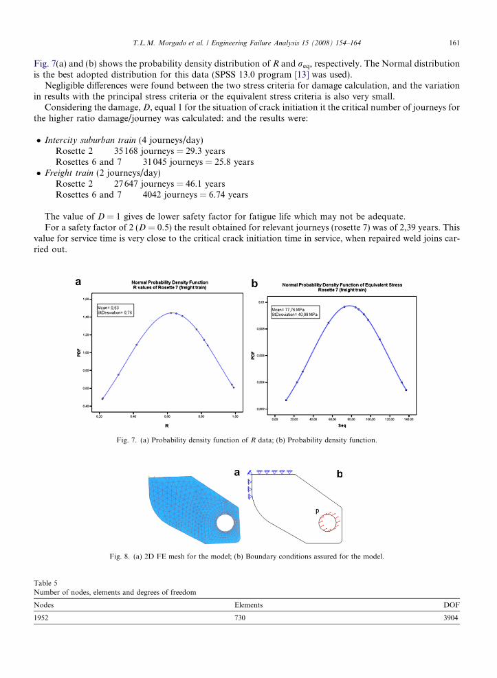
Fig. 8. (a) 2D FE mesh for the model; (b) Boundary conditions assured for the model.
Table 5Number of nodes, elements and degrees of freedom
Nodes Elements DOF
1952 730 3904

Table 6Data values of the supporting reaction force, R
Angle (�) Position Force (N)
90 Sl 33060690 Seq 225679
270 Sl 572320270 Seq 239132
0 Sl 2484720 Seq 241443
180 Sl Tensao = 0180 Seq 301804
45 Sl 23486145 Seq 212733
225 Sl Tensao = 0225 Seq 212733
135 Sl Tensao = 0135 Seq 260771
315 Sl 327298315 Seq 260771
30 Sl 23234230 Seq 219392
60 Sl 25032160 Seq 213219
120 Sl 619150120 Seq 252854
150 Sl Tensao = 0150 Seq 263330
210 Sl Tensao = 0210 Seq 219392
162 T.L.M. Morgado et al. / Engineering Failure Analysis 15 (2008) 154–164

Table 6 (continued)
Angle (�) Position Force (N)
240 Sl Tensao = 0240 Seq 213219
300 Sl 377126300 Seq 252854
330 Sl 294909330 Seq 263330
22.73 Sl 23142322.73 Seq 221790
T.L.M. Morgado et al. / Engineering Failure Analysis 15 (2008) 154–164 163
5. Numerical simulation
Fig. 8(a) shows a 2D Finite Elements mesh of the model. The finite elements code ANSYS was used and thetype of elements was the 8 nodes isoparametric. Near the support eye the mesh was refined.
The boundary conditions of the computational model are identified in Fig. 8(b). The loading, p, as appliedof form to obtain the values of principal and equivalent peak stresses, measured in service. Table 5 gives thedetails of the mesh that produced more consistent results.
Since the support force, in operation, is revolving in order of time it was admitted that reaction resultantwill have values to occur with a direction, h, changing in the plan of support joint. In this way, was obtainedthe supporting reaction force in support eye, R, for h of 30 in 30� and for the direction angle of principal stress,22.73� using the following equations:
R ¼ Ap; ð11ÞA ¼ 2prl; ð12Þ
where p is the load applied in FE simulation, A is the contact surface area of the bore with the pin, r is the boreradius and l is the support pin thickness.
Table 6 presents the data values of the supporting reaction force, R, obtained for each angular position andfor the principal and equivalent stresses measured in service (rosette 7). The results of supporting reactionforces are significantly independent of h until angle of 60� and are high for forces between 220 kN and230 kN (experimental results).
6. Conclusions
Of the values of the supports reactions and the fatigue behaviour of the driving gearbox, the following con-clusions can be taken off:
� The steel to carbon of the box body (St22-3) does not possess the level of resistance and the ductilityadjusted for this application.� Although the steel of the box cover (St37-2) to possess better mechanical characteristics than St22-3 steel, is
neither indicated for this type of application.� Tensions level measured in the driving gearbox with the electric strain gauges is raised, what originates
problems of fatigue cracking, especially in the critical zones (weld zones).� Reactions in the superior lateral supports had given very high values.

164 T.L.M. Morgado et al. / Engineering Failure Analysis 15 (2008) 154–164
� The results of supporting reaction forces are significantly independent of h until angle of 60� and are highfor forces between 220 kN and 230 kN.� Fatigue damage presented high values.� Calculations of safe life gave values very close to the life values obtained in service for the driving gearboxes
where fatigue cracks were detected.
Acknowledgements
The authors are thankful to CP (Portuguese Railways Company) and to EMEF, S.A. (company of the CPGroup).
References
[1] Weihua Zhang, Pingbo Wu, Xuejie Wu, Jing Zeng. An investigation into structural failures of Chinese high-speed trains. Eng FailureAnal 2006;13(3):427–41.
[2] Gu Diankang. Test analysis of frame intensity of 209 serie bogie. Railway Locomotive Car 2002;22(4):11–2.[3] Infante V, Branco CM, Brito AS, Morgado TL. Failure Analysis of cast steel railway couplings used for coal transportation. Eng
Failure Anal 2003;10(4):475–89. Agosto.[4] Sonsino CM. Structural durability of cast aluminium gearbox housings of underground railway vehicles under variable amplitude
loadings. Int J Fatigue 2005;27:944–53.[5] Sonsino CM, Kaufmann H, Foth J, Jauch F. Fatigue strength of driving shafts of automatic transmission gearboxes under
operational torques. SAE paper 970706 (1997); SAE Transactions Section 5. J Mater Manufact, USA 1997, 635–48.[6] ASTM, Specification for tensile testing of cast ferrous materials. American Society for Testing and Materials, USA, E8 specification,
1992.[7] Branco CM, Ascencao L, Infante V, Costa C, Morgado TL. A failure analysis study of cast steel railway couplings used for coal
transportation – Part I: Analysis of fatigue Damage and Stress Analysis. In: Proc Eighth Portuguese Conf on Fracture, Setubal,Portugal 2002, 449–61.
[8] Ascencao L. Private report from UMAT/CP, Engineering Department, Lisbon, 2002.[9] Branco CM, Ferreira JA, Costa JD, Ribeiro AA. Design of Machine Elements. Lisbon: Calouste Gulbenkian Foundation; 2005 [in
Portuguese].[10] Radaj D. Design and analysis of fatigue resistant welded structures. Cambridge, UK: Abington Publishing; 1994.[11] Maddox SJ. Fatigue Strength of welded Structures. second ed. UK: Woodhead Publishing; 1991.[12] Eurocode 3, Section 9, Regras de projecto a fadiga de estruturas soldadas de aco. 2001.[13] SPSS Advanced Models 6.13, 2004 SPSS Inc.
Related Documents