
Welcome message from author
This document is posted to help you gain knowledge. Please leave a comment to let me know what you think about it! Share it to your friends and learn new things together.
Transcript

8/8/2019 A Evaluation of the Duration of Fly Through Obtained When Tracking with the Speed Ring Sight on the M-55 Weapon
http://slidepdf.com/reader/full/a-evaluation-of-the-duration-of-fly-through-obtained-when-tracking-with-the 1/28

8/8/2019 A Evaluation of the Duration of Fly Through Obtained When Tracking with the Speed Ring Sight on the M-55 Weapon
http://slidepdf.com/reader/full/a-evaluation-of-the-duration-of-fly-through-obtained-when-tracking-with-the 2/28
L
DEFENSE TECHNICAL INFORMATION CENTER 8725 JOHN J. KINGMAN RD. STE 0944
FT. BELVOIR, VA 22060-6218
"""... Il DLY
,. DTIC-R (FOIA 2010-70) JUl 23 2010
Mr. John Greenewald, Jr.
Dear Mr. Greenewald:
This is in response to your email dated July 14,2010 (enclosure I) requesting information under
the Freedom of Information Act (FOIA). Under Department of Defense rules implementing the
FOIA, published at 32 CFR 286, your request was categorized as "other."
Document ADB95 171 7 is approved for public release and provided at enclosure 2. For your
information, we have initiated action to have the document processed in order to enable it to be
viewed and/or downloaded in full text through the DTIC Online Public Technical Reports
website at http://www.dtic.mil/dtic/searchitr/index.html. Once that process is completed, you
can visit the above site and fo llow the following instructions: In the "Search for" box, type the
full document number as it's written above (ADB951717), then click the "Search" button; last, in
the Accession Number field, click on the link "View Full Text (pdf)".
To date, there are no assessable fees for services from the Defense Technical Information Center
(DTIC). Please understand that other members ofthe public may submit a FOIA request forcopies ofFOIA requests received by this office, or the names of those who have submitted
requests. Should such occur, your name and, if asked for, a copy of your request will be
released; however, your home address and home telephone number will not be released. Other
private citizens who have obtained your name by using such a request may contact you;
however, correspondence from the Defense Department about your request will be on official
letterhead. Please contact me at (703) 767-9204 if you have any questions. Thank you for your
. interest in obtaining information from DTIC.
Sincerely,
UJ2 Enclosures MICHAEL A. HAMILTON
Acting FOIA Program Manager
8/8/2019 A Evaluation of the Duration of Fly Through Obtained When Tracking with the Speed Ring Sight on the M-55 Weapon
http://slidepdf.com/reader/full/a-evaluation-of-the-duration-of-fly-through-obtained-when-tracking-with-the 3/28
UNCLASSIFIED ADB951
Evaluation of the Duration of Fly Through Obtained
When Tracking with the Speed Ring Sight on the M-55
Weapon
HUMAN RESOURCES RESEARCH ORGANIZATION ALEXANDRIA VA
DEC 1968
Approved fo r public release; distribution is unlimited.
8/8/2019 A Evaluation of the Duration of Fly Through Obtained When Tracking with the Speed Ring Sight on the M-55 Weapon
http://slidepdf.com/reader/full/a-evaluation-of-the-duration-of-fly-through-obtained-when-tracking-with-the 4/28
UNCLASSIFIED
Redistribution Of OTIC-Supplied Information Notice
Al l information received from DTIC, not clearly marked "for public release" may
be used only to bid on or to perform work under a U.S. Government contract or
grant fo r purposes specifically authorized by the U.S. Government agency that
is sponsoring access OR by U.S. Government employees in the performance of
their duties.
Information no t clearly marked "for public release" may not be distributed on the
public/open Internet in any form, published fo r profit or offered fo r sale in any
manner.
Non-compliance could result in termination of access.
Reproduction Quality Notice
DTIC's Technical Reports collection spans documents from 1900 to the present.
We ·employ 100 percent quality control at each stage of the scanning and reproduction process to ensure that our document reproduction is as true to the
original as current scanning and reproduction technology allows.
However, occasionally the original quality does no t allow a better copy.
If you are dissatisfied with the reproduction quality of any document that we
provide,please free to contact our Directorate of User Services at
(703) 767-9066/9068 or DSN 427-9066/9068 fo r refund or replacement.
Do Not Return This Document To OTIC

8/8/2019 A Evaluation of the Duration of Fly Through Obtained When Tracking with the Speed Ring Sight on the M-55 Weapon
http://slidepdf.com/reader/full/a-evaluation-of-the-duration-of-fly-through-obtained-when-tracking-with-the 5/28
UNCLASSIFIED
AD NUMBER
ADB951717
NEW LIMITATION CHANGE
TO
Approved fo r pub l ic r e l ease , d i s t r i bu t i on
unl imi ted
FROM
Dis t r ibu t ion author ized to u.s. Gov ' t .
agenc ies and t h e i r con t rac to rs ;
Adminis t ra t ive /Opera t iona l Use; DEC 1968.
Other r e q u ~ s t s sha l l be re fe r red to
Depa+tment o f the Army, Attn: Publ ic
Affa i r s Off ice , Washington, DC 20310.
AUTHORITY
HUMRRO D/A ltr 8 Ju l 1980
THIS PAGE IS UNCLASSIFIED

8/8/2019 A Evaluation of the Duration of Fly Through Obtained When Tracking with the Speed Ring Sight on the M-55 Weapon
http://slidepdf.com/reader/full/a-evaluation-of-the-duration-of-fly-through-obtained-when-tracking-with-the 6/28
TH!S REPORT HAS BEEN DELIMITED
AND CLEARED FOR PUBLIC RELIASE
. . UNDER DOD DIRECTIVE 5200,20 AND
NO AESYRICTIONSAREIMPOSED UPON
ITS USE AND D I S C L ~ S U R E o .
DISTRIBU!ION STATEMENT A
APPROVED FOR PUILIC RELIASEJ
DISTRIBUTION UNLIMITEDe

8/8/2019 A Evaluation of the Duration of Fly Through Obtained When Tracking with the Speed Ring Sight on the M-55 Weapon
http://slidepdf.com/reader/full/a-evaluation-of-the-duration-of-fly-through-obtained-when-tracking-with-the 7/28
. , . -; . . - " ..• • "
, ,
I UNANNOUNCED - j)
I
Ii,
DnmRROl '
<· ,. I
,, , .
I 'f""'f
...
·<, i. - .- I l"""!
!
I
I t:Q
0 <:(
,; ' .
[ \\
I(\/DTlC'-1SELECTED
JUN 4 1980 <
B
....vThe George WashinglQn IJniversityl'J 'IIml/\N m:SOUIlCIlS IlIlSMIlCIl OF(1U;Ef
operating nnder contract with
TIlIl DEPAIlTMENT OF TUE AlUir
o,
U80 5 '1f23 014
LLJ r-- ' , ,Li; Approved for public release;
dist ribution unlimlled
,

8/8/2019 A Evaluation of the Duration of Fly Through Obtained When Tracking with the Speed Ring Sight on the M-55 Weapon
http://slidepdf.com/reader/full/a-evaluation-of-the-duration-of-fly-through-obtained-when-tracking-with-the 8/28
, .
]1"T
Th is material hos been prepared for review by appropria te
research or militot), age ncies, or to record research inComotion ,on 0 11 interim basis.
The contents do not necess arily reHe ct the oHicial opinion
or policy of either the lIulUoli c s o u ~ c e s Research OUiee or the
Department of th e Anny. . "
]
} ] ,... I
I ) I"..;; I
]I.
I
I
I
I•
Ii
r
Tile lIuman Resources Rescarch OHice is a nongovernmenta l. ..,.
ngency of T he George Washington Un ivers ity. operating under
contract with the Department of the Army . llumnnO's mission Ii'is to conduct research in the fi elds of lroioin.8. motivation,
' .1••d leadership.
:)
Ii
,I'

8/8/2019 A Evaluation of the Duration of Fly Through Obtained When Tracking with the Speed Ring Sight on the M-55 Weapon
http://slidepdf.com/reader/full/a-evaluation-of-the-duration-of-fly-through-obtained-when-tracking-with-the 9/28
• . ...
~ ; :
•
TVPE OF REPORl' b PEUIOD COVERED
OF,J..LY .!..HROUGH Staff Paper
InTH THE SPEED RING [lGH!:.:I..-PEiiFOiiiiiiH""GOiiiG."iiEP;;;;;rtiiiiiBirn-l..... ""- '"
d I H ; ; r o l d ~ ~ ; l C h ~ i s t e n ~ e n .
~ ~ ~ ; ; ; ; ; ~ ~ ~ ~ ; ~ : . : . - - = ~ / ~ ~ ~ ~ D A - 4 4 - l 8 8 - A R d - 2 ' ~ = - - /.. ; ; ; ~ ; . = = - /""",
Human Resources Research Organization (HumRRO)
300 N. Washington Street
11. CONTROLLING OFFICE NAME AND ADDRESS
Department of the Army
Unclassified
,.
•>:;
. .. Approved fo r public release; distribution unlimited .
•
17. OISTRIBUTIOH STA TEM ENT 70.
:..:.'
Research performed under HumRRO Project SKYFIRE .
. n llmb er)KEY WORDS on ,.".rslt
firing techniqueslead f ~ r i n g technique
antiaircraft weapons
gun sightstracking
(ConllfJUe Dr! r . Y . r ~ ! , In studying the various firing or strategies that might be used
opera ting conventional antiaircraft weapons, saveral strategies might be en-
umerated. One of th e more commonly used is the constant lead firing tech-·
, niq\\c . This report presents an evaluation of th e effectiveness of the constant lead technique on the bas1s of the "eapon s peed ring characteristicsof th e M-l8 Reflex sight mounted on th e quad .50 caliber M-55 weapon,ing optimum tracking performance.
DD I ~ ~ ~ 3 1473 EDlnO" OF I nov 65 IS OOSOLETE
SECURITY CLASSIFIChYrON 0': TillS PAGE ("""on D.,. Enlorcod)

8/8/2019 A Evaluation of the Duration of Fly Through Obtained When Tracking with the Speed Ring Sight on the M-55 Weapon
http://slidepdf.com/reader/full/a-evaluation-of-the-duration-of-fly-through-obtained-when-tracking-with-the 10/28
., ... . ..,
J(!)
.." . .
"
LI\.
I
fStaff Paper
J EVALUATION OF THE DURATION OF FLY THROUOH
O B ~ I r l E D WHEN TRACKING WITH THE SPEED RING SIGHTION THE M-55 WEAPoN
I by
Albert L. Kubala
[ and
Harol d E. Christensen
OeCe'7l1BE1R.. I &i6q
[r.-
2:This Staff Paper has been prepared for dissemin. t 1cn within HumRRO fo r purposes of information or t i o n internal to the organization. I t does not nece ssarily [represent official opinion or policy of either th e HumanResources Research Office or the Department of t ~ e Army .
r.
, .. December 1968
rHumRRO Division No. 5 (Air Defense)
OTIC...
...
ELECTEDThe George ,Iashington University
JUN4 1980 :[ ilUMAN HESOURCES RESEARCH OFFICE operating under contract With SHE DEPARTlo!ENT OF TIlE ARMY
! B
[ A p P ~ o v e d for public release .
dIstribution un lim ited .
-- ._

8/8/2019 A Evaluation of the Duration of Fly Through Obtained When Tracking with the Speed Ring Sight on the M-55 Weapon
http://slidepdf.com/reader/full/a-evaluation-of-the-duration-of-fly-through-obtained-when-tracking-with-the 11/28
- - - - - - ------- --- - - -,
, .
l
I
•
PREFACE
-
., The data presented in the paper were collected in connection','ith research being conducted under HumRRO Work 'Jnit SKYFlRE •. -'
In studying the various firing techniques or strategies which
l might be employed in the operation of conventional anti-aircraft
I
weapons, several strategies might be enumerated. One of the morecommonly used is the constant lead firing technique. This reportpresents an evaluation of the effectiveness of the constant lead
technique on the basis of the weapon speed ring characteristicsof the ~ 1 - 1 8 Reflex sight mounted on the quad .50 caliber 14-55weapon, assuming optimum traCking performance.
I
I I [
[
l i
[
[
[
r..
[i i i
, [
[
I.CCESSION lor
NllS White Section 0
one Duff Section 0
UN,NHOU:iCEO
!USll, IC-" ION - --- -1....... .... ...._............. .._-""" BY ,. ,
O ~ 1 i ! r n U l I O H f A V A I U m U i Y ctrom,l. AVAIL. ,nd/or Sl'f.CI!l.

8/8/2019 A Evaluation of the Duration of Fly Through Obtained When Tracking with the Speed Ring Sight on the M-55 Weapon
http://slidepdf.com/reader/full/a-evaluation-of-the-duration-of-fly-through-obtained-when-tracking-with-the 12/28
- --- '.;:,:
IINTRODUCTION
[.Obtaining hits with an anti-aircraft gun is primarily a function
of tracking accuracy, proper elevation adjustment of the sight, andchoice of proper lead angle . This report is concerned >lith examiningone methoc. which has been 'lsed to solve the problem of detern:iningproper lead angle- -the speei ring sight, The M18 reflex sight ~ r o -jects .. reticle image ur 'O:I an . inclined glass plate. As the gunner
[ looks through the inclined plate he sees the target and the reticleimage. The reticle image contains four concentric circles termedthe 100, 200; 300 and 400 miles per hour speed_ ril,gs. Figure 1 repl'e
I·
sents a target as i t m i ~ h t be viewed through the reticle . The speed[ rings have been labeled in the f;gure fo r clal·ity. The rings are not, labeled on the sight i tself. When only a z i ~ u t h is being conSidered,
the center line of sight is equal to the bore sight ("enter of sight)
[of the weapon. The a n g ~ e between tha center line of ,-igh. and the
l i n ~ of sight through any speed ring is a1>lays a constant value.
The purpose of th e speed ring is , of course, to d e t ~ r m i n e theJ. amount of lead anrle necessary to compensate fo r the differences
between the time of flight of both target and round so that the, rounds fired " i l l have an optimum chance of hittir,g the target.. UnfortunateLY, no constant lead angle can be o p ~ i m l ~ at a l l pOints
along the target 's path. As the target approaches crvssover, fo rexample, the angular velocity of the target, relatiVe to the glli1
[ position, increases. Stated another way, as the targot approachescrossover, i t travels a continually decreasing a m c u ~ t of actualdistance when passing through a given angular distance relative
I: to the weapon. In pr..lctice, as a target is acquired, the gunner
may select a certain fixed lead angle (speed ring). Ilben he f i rs tbegins to fire at the target, the lead ap.,le se lecte ': r.t'l:; cause the
fire to lead the target. Assuming the target continues at the same[ speed and direction, i t should reach a point at "hi ·o;' the lead apgleselected will place the fire (theoretically, at l e ~ o t risht on thenose of the target . As the target continues, the preni cted point
[ of fire will follow down the target until i t reaches tbe tai l andeventually, as the target continue" toward crossover (midpoi.nt),the firing point may lag the target. This same pre:ess is essentiallyrepeated in reverse as the gunner continues to track the target after[ crossover . Thus, whell the speed ring sight is used, the rounds firedwould be predicted to hit the target during only a limited amount of
the time in which the target can be tracked . This period, during
1:which target hits would be predicted, is termed a "fly through". Theterm "adequate . fly through" is used in this study te indicate a flythrough whic'h occurs within the effective range of the weapon.
r
I:r..,
- -- - .. . -- - -- --------

8/8/2019 A Evaluation of the Duration of Fly Through Obtained When Tracking with the Speed Ring Sight on the M-55 Weapon
http://slidepdf.com/reader/full/a-evaluation-of-the-duration-of-fly-through-obtained-when-tracking-with-the 13/28
.-100 200 300 400
i
a:
I
'"
•[ ,,"
"
•• r [
[
, I.:
[
LFigure 1. Schematic Representation of Target as Viewed Through
Speed Ring Sight
[
r.
r:
2

8/8/2019 A Evaluation of the Duration of Fly Through Obtained When Tracking with the Speed Ring Sight on the M-55 Weapon
http://slidepdf.com/reader/full/a-evaluation-of-the-duration-of-fly-through-obtained-when-tracking-with-the 14/28
" : .--
I:I. If an inappropriate speed ring is selected, . the lead an!;).e may
be either too large or too small , sO that fire will lead or lag thetarget at all tintes and no through will be obtained. Targetspeed obviously has a very great effect on the selection of an cpti mum speed ring. However, since range of target, as well as speeu,affects the lead angle r e q ~ i r e d , i t cannot be c a t e g o r i c a l ~ stated~ h a t an aircraft t r a v ~ l H n g at a given speed should always be trackedusing the same s,:,,,ed ring.
On +!.e ~ 1 - 1 8 sight, the :niles per hour values. of the speed rings• [ arp ..at to be interpreted d i r e c t ~ . Firing doctrine states that~ a r g e t s should be tracked with· a speed ring equal to 3/4 of the targetspeed.l I There is , however, some question as to whether an adequate
[ through can be ·obtained at all ranges following this doctrine. .
The question as to how much latitude is allowable in the estimation of target speed also further complicates the firing problem.
[
r I f , fo r example, there are some situations in which only a l ' e l a t i ' l e ~ small error in target speed estimation would result in not obtaining a f ly through, this would impose serious limitations . .
To evaluate e f f e ~ t " v e n e s s of a speed ring sight, i t was considerednecessary to compute the location on the target path where throughwould occur undo:. various conditions of crossover range, target speed,and choice of speed ring . Three questions wer£ of primary concern :(1) Under what conditions "i l l through be obtaine,,? (2) What i sthe duration of through? (3) ~ 1 h e r e along the tracking course,with respect to crossover, does the through occur?
The kind of information needed was obtained by plotting the angulardistance at which a fly through will occur under various combinationsof target speeds, crossover ranges and speed rings .
r·, Conditions of fly through were predicted by the formula
[
YDepartment of the Army, Field Manual 44-57, Service of the Piece Multiple Caliber .50 ~ A c h i n e Gun, 7 September 1951, p. 100 .
r3
(
I.

8/8/2019 A Evaluation of the Duration of Fly Through Obtained When Tracking with the Speed Ring Sight on the M-55 Weapon
http://slidepdf.com/reader/full/a-evaluation-of-the-duration-of-fly-through-obtained-when-tracking-with-the 15/28
where R = Crossover ::ange.
= angle between crossover and line of sight usingthe chosen speed ring (when tracking the nose of
the target).
Q = engle between crossover and bore sight (center ofL sight) •
V = velocity of target •. t
• T = time required for round fired to reach predicted
intercept.
The first half of the equation--R(Tan - Tan Q) --represents the. .'.
;.
,.L
.
R
distance which the target must travel from fire to intercept asdetermined by the l ead angle of the speed ring sight. The secondI . half of the equation--V,,(T ) - - represents , he distance which the;1 Rtarget will travel based on target speed and weapon ballistic data.Using assumed values of target spe,ed , crossover range and speedring, the value for angle Q was obtained. The value of Q was used
o to determine the distance from crossover at which the fl y throughwould be predicted to cvromence . To predict the end of the fly
j:. through, the quantity of 16 yds. (representing the target length)
'. was added to the product on the left side of the equation. Thevalue 16 yds . is, of course, arbitrary and is not intended to implyany actual .aircraft length. I t should be noted that computations! were based on tracking the nose of ·the target, while weapon doctrineadvocates tracking center of mass . This was done because center of
mass is not an easily measurable quantity, differing as i t does from
I. one aircraft type to another. Angular areas of fly through using .{ ' center mass tracking will differ sl ightly from those reported in
this study.
I. T;.e angles between speed rings and the center line of sight were
L; deternined empirically by two d i f f ~ r e n t observers. The speed ring
values used in this study were as follows:
Ana le from Center Line of SightSlleed Ril;a
3.655°1000
7.516
200
11.92003000
16.918
400
r[-
4

8/8/2019 A Evaluation of the Duration of Fly Through Obtained When Tracking with the Speed Ring Sight on the M-55 Weapon
http://slidepdf.com/reader/full/a-evaluation-of-the-duration-of-fly-through-obtained-when-tracking-with-the 16/28
I,
J..
I
I
I
I. L [
[
r !
Crossover ranges were selected (within the effective range of
the weapon) and fl y through 'paths computed fo r a sample of speedring-target speed combinations,
RESULTS
Figure 2 presents an example of three tracking plots using the300 speed ring to track targets at a crossover range of 500 meters .Assuming perfect tracking, the figure shows where rounds fired atvarious angular distances prior to crossover would be predicted tolead, lag, or hit the target. For instance, assume a weapon is tracking a 404 mph target at this range with the 300 speed ring; at 25
0
before crossover the round would be gredicted to lead the target
by approximately 9-1/2 meters, at 20 the round should just hitthe nose of the target, at crossover (0
0) the round should hit the
ta i l of the target. ( ~ n e target was assumed to be 16 meters longin computations.) Again, using the same speed ring to track a 624mph target flying at the same range, a round fired at 43
0prior to
.:,'ossover would be predicted to lag the 'nose of the target by appraximatcly 27 meters. It can be noted that if a target slower than 355mph W· ," tracked, using this speed ring, the fire would alllays leadthe t a r g ~ If targets at speeds greater than 624 mph are tracked,the range' t" ·,he aircraft at the time of fly through will be beyondweapon effecti\', range. The three tracking plots in Figure (355mph, 404 mPh, aDa mph) illustrate respectively, a minimum, optimum,and maximum targ(t ..peed. The minimum seed for fly thrOugh was defined
here as the slolles target speed at a given crossover range) at whicht h ~ speed ring usen will obtain a hit. Under this condition, the projectiles would be predicted to just hit the nose of the target atcrossover (assuming perfect tracking; . :;:he optimum speed for f ly
through was defined as that target speed which Yields a complete fl ythrough surrounding crossover. This is the longest fly ' through obtainable in terms of both time duration and angular distance. Themaximum speed fo r 'fly th:-ough was the maximum target speed at whicha fly through can be obtained within the weapon's effective rangewhich, fo r the computations performed, was assumed to be Boo meters .Figure 2 illustrates the minimum, optimum, and maximum target speedsfor obtaining fly through under only one set of range-speed ringconditions. Since variation in range of target had an effect onfly through, i t was felt that, fl y through data should, be examinedacross several target crossover ranges .
~ I i n i m u m , optimum, and maximum target speeds for obtaining f ly
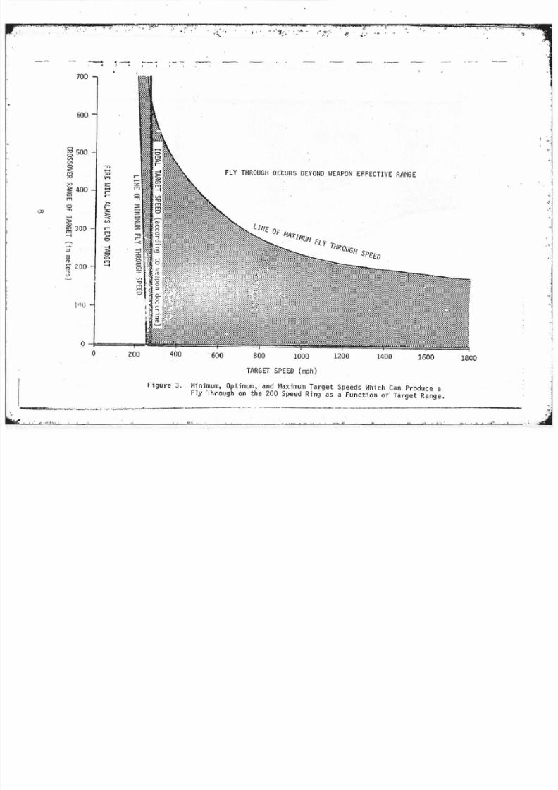
through at several target rangeR are presented in Table 1. InFigures 3: 4, and 5, the minimum and maximum target speeds which
5

8/8/2019 A Evaluation of the Duration of Fly Through Obtained When Tracking with the Speed Ring Sight on the M-55 Weapon
http://slidepdf.com/reader/full/a-evaluation-of-the-duration-of-fly-through-obtained-when-tracking-with-the 17/28
. ,.
'.
"."
'"j :
.
•
" . '
I
!L, \, I,
:.,
L·
r:
l
l[
[
[
[
r, 'r- .
'r
AREA OF PREDICTED FLY THROUGH
.,..E'
.:l
.c:0E.,.
r-----'Al..._---.
N- = : = : : : : : ~ ' " - L . . ~ _ - - - ! APPROXIMATE tIM!! OF THE EFFECTTVtRANG Ur.THE WEAPON
r - - - - - - ~ I - - - - - - ~ - - - - - - ~ - - - - - - ~ - - - - ~ ~ - - - - - - ~ O g 0 S ~ ~ + + + I I I
01 FFERENCE (i n meters1 BETWEEN THE PREDICTED POSITIONS OF ROUND AND TARGET
6
-- -,,-. . _.. -. -. -
o.,.
oM
oN
o...
o....8'
'"..'"c:
. c " ,; ' : "0..OJ. ,'" QC:'"
'""''''J. .o"0 >J. .
0'"" '>''' 0
O J ' ~
....."J. .o
J.. ....'"
U....">UJ
.... '". . J..:>: ",
V) t '" 0
u'" ",u
'">: .... J..0
"'
" ' t -
Il: .co
::> ....UJ 0",'"
J..C:.c<!>..
...,'" ... '"CI >.""0.' . Cl.
..... .,
..Q
"0 '"
.... 0uo' ~ MOJ""...c:
Co. ....
N
.. J..
0>
.....
~ ' - - ' - -

8/8/2019 A Evaluation of the Duration of Fly Through Obtained When Tracking with the Speed Ring Sight on the M-55 Weapon
http://slidepdf.com/reader/full/a-evaluation-of-the-duration-of-fly-through-obtained-when-tracking-with-the 18/28
- - - : : ~ . . . -.
II,
Il'.\
: I, I
L
TABLE 1Characteristics of Fly Through: as Determined by
Range and Aircraft Speeds
l.Crossing Range Minimum Optimum Haximum Target Speed Which
and Target Target Allows a Fly ThroughSpeed Ring Speed Speed Within an 800 yd Slant Range
700M - 2 209 mph 242 mph 226 mph[ 3 334 mph 368 mph
g
371 mph
4 482 mph 515 mph 551 mph
500M - 2 222 mph 271 mph 358 mphJ 3 355 mph 404 mph 624 mph 4 511 mph 560 mph . . 1041 mph
I
1 3 0 0 ~ 1 - 2 235 mph 322 mph 716 mph
3 376 mph 463 mph 1525 mph · 4 542 mph 629 mph 3537 mph
l.200M - 2 243 mph 378 mph 1373 mph
3 390 mph 541 mph 3500 +mph4 561 mph 697 mph 3500 +mph
100M - 2 245 mpl> 517 mph 3500 +mph3 393 mph 665 mph 3500 +mph[ 4 566 mph 838 mph 3500 +mph
[
[
[ Computed optimum target speed produces a fly through which is
beyond effective range of the weapon.
7
8/8/2019 A Evaluation of the Duration of Fly Through Obtained When Tracking with the Speed Ring Sight on the M-55 Weapon
http://slidepdf.com/reader/full/a-evaluation-of-the-duration-of-fly-through-obtained-when-tracking-with-the 19/28
• " . 1,. .,:.- , . ' ,. """;. ' • ..f'.:1. .," '.
~ - ' I • . - • •
700
600
o I o 200 400 ' 600 800 1000
FLY THROUGH OCCURS DEVONO WEAPON EFFECTIVE RANGE
LINE OF I1I1XINUN
FL Y 'THROUGH SPEED
1200 1400 1600 1800
TARGET SPEED (mph)
Figure 3 , Minimum, Optimum, and Maximum Targ et Speeds Which Can Produce a
- _ '_ _ . ny " co"," ' " ' " ' " ' " " : ~ " ' ' ' ' " " , , , , , , eo"", ,
- .!.. -, :.',. . ,""----<------ . " ~ - ' - __

8/8/2019 A Evaluation of the Duration of Fly Through Obtained When Tracking with the Speed Ring Sight on the M-55 Weapon
http://slidepdf.com/reader/full/a-evaluation-of-the-duration-of-fly-through-obtained-when-tracking-with-the 20/28
• ,
a;"
-I
L o"'".I.
o .. "'":; '" .. "
-0,'"0'",.. '""-f'" ... . t
t.> ...."N 0:0
U
- - ":0::::::;;
" 'u-oe
"'''"'''-'" VI'"'"-" ...
0 .
'"·1 "'''': f'",.
" ,e.5- ... .e '"
w , , -0'"e'"
"-"w
"I xc .Xl'" "'VI
t -W "'0
-00
'" ,,'"'"'"-
'" "0:e ...
0 " "e0
'" ...0 . 0 :
0'"
_0".., , 0 :eo-~ ~ ~ ~ ~ ~ ~ :fG:
MIN1I1UM FLY THROUGH SPEEO
o
r
l. ,-
1.
FIRE LEAOS TARGET
<>....r0
0'"'"o o o . g
o o g8M N'"
CROSSOVER R A ~ ~ E OF TARGET (in meters)
9

8/8/2019 A Evaluation of the Duration of Fly Through Obtained When Tracking with the Speed Ring Sight on the M-55 Weapon
http://slidepdf.com/reader/full/a-evaluation-of-the-duration-of-fly-through-obtained-when-tracking-with-the 21/28
700
" " ',.' - , ,..
"'
"
FLY THROUGH OCCURS BEYOND vlEAPDN EFFECTIVE RANGE00
n:; 0
V>
V>
0500
0< :
.".....
:; 0-" .....,..r-".....'" 400
.....'"V>"
."-t
0 ,.t : ; 0
G'> '"".....'" -t
..... 300"-t
"3<1)
rt - 2001)
-.
IDEAL TARGET SPEE D ( a C C O r d i n ~ to ' , e a p o
100 -1doctrine
o I I ,io 200 400 600 800 1000 1200 1400 1600 1800
TARGET SPEED (mph)
Figure 5, Minimum, Optimum, dnd Maximum Target Speeds Which Can Produce aFly Through on the 400 Speed Ring as a Function of Target Range.

8/8/2019 A Evaluation of the Duration of Fly Through Obtained When Tracking with the Speed Ring Sight on the M-55 Weapon
http://slidepdf.com/reader/full/a-evaluation-of-the-duration-of-fly-through-obtained-when-tracking-with-the 22/28
••
,. c' ·
" ,
L
L are predicted to produce a fly through are plotted as a f ~ ~ c t i o n oftarget crossover range. These three figures present the information
[ separately fo r the 200, 300, and 400 speed rings.
An examination of Figure 3, fo r example, will indicate that if
the 200 speed ring is selected for tracking a target which is travel-
r
[ ling at 300 mph, an adequate fly through will occur at the closer
midpoint ranges. Hmlever, if the target is beyond 600 meters atc r o s s o v e ~ the fly through will occur auring a portion of the targetspath which is beyond effective range. In Figure 5 i t should be .noted that, i f the 400 speed ring' is selected for tracking a targettravelling at 500 mph (an apparently reasonable choice), no flythrough would be predicted to occur.
During an actual engagement of a target by the weapon a situation
exists in which the gunner is required to select a speed ring based[ on his estimation of target speed. Figure 6 presents such a situation
to allow comparison of the results obtained from the various speedring choices which might be made. The target represented in Figure 6is travelling a ' ~ 460 ·mph with a midpoint range of 500 meters from ther. w ~ ~ ~ o n pOSition. The figure illustrates the results ~ h i c h would bepredicted fe r each of three possible speed ring choices. If the 400speed ring is chosen fo r tracking, no fly through would be predicted
r
r to occur. Predicted fire would always lead the target b)' at least16 meters. If th e 300 speed ring is seLected, a fly through "ould bepredicted to occur between 310 and 22 0 before crossover . If th e 200s p ~ e d
ring .is
selected, a fly through should occurb e t ~ e e n
580
and 560
before crossover. However, this would plaCE the !lj' through at appro-Ximately 1000 meters, which is beyond the effect:"e range limi t assume.din this study. At the 1090 meter range, while hits would cer-r tainly be pOSSible, the likelihood of hits would be scbstantially reduced. .
[ I t should be noted that a ll computations were ~ d e using only the portion of the target path prior to crossover . A comparable fly through pattern will also occur after crossover, but the BnBle and duration will not be .precisely the same as for the fly through which occurred before crossover.
r DISCUSSION
r The information derived "is summarized as follows:"'"
1. Under what conditions will no f l ~ through be obtained?t"I.
11

8/8/2019 A Evaluation of the Duration of Fly Through Obtained When Tracking with the Speed Ring Sight on the M-55 Weapon
http://slidepdf.com/reader/full/a-evaluation-of-the-duration-of-fly-through-obtained-when-tracking-with-the 23/28
,
JAREA OF PREDICTED FLY THROUGH.L
L· I:
. Lr
'
1:
[
r - APPROXIMATE LIMIT OF THE
A
. -~ '"t;=:UJ
0 -
VI
oo'N
o.....
.,..
0 '-"<0
>
. c ; " ,0 . " ,
'"
E co · ~ <0 ' ".,.
0"' ."..
..
" , 0 ."'", CV l
UJ
>""0o vo
EFFECTIVE RANGE OF THE IIEAPON VI " ' . , .VI ' -0>-'"
'" cI: u c '" '.'°5VlOO : : : - ~ . r J o
u.
VI " .UJ . .'" 0
UJ '" 0- I: '"J'..,...o . , . c ;
10 u.,M
'". =,r ....
"-'"
'".'0 ...[N, ",
, '".
[ ". .
0
r4.
[. r - - - - - - , - - - - - . - - - - - _ - - - - - - _ r - - _ - - , _ - - - - - -o o o <0 0oM N
+ + I I I+J2
DIFFERENCE (in meters) BEThlEEN THE PREDICTED POSITIONS OF ROUND Aim TARGET.
12

8/8/2019 A Evaluation of the Duration of Fly Through Obtained When Tracking with the Speed Ring Sight on the M-55 Weapon
http://slidepdf.com/reader/full/a-evaluation-of-the-duration-of-fly-through-obtained-when-tracking-with-the 24/28
.
T IL
I
I I .
t.
l. I
II .I . .
I':
[
C.
r
,
a. No fly through will result when target speed is too
slow fo r the speed ring selected. From observingthe line of minimum fly through speed in Figures 3,
4, and 5, i t can be seen that the minimum target speedto obtain fly through appearn to be linearly related
to range. Although there i s some variation at differ-ent ranges, roughly speaking, fly through will not beobtained if speed rings are used for targets slowerthan the folloWing:
Speed Ring ~ u Target SpeedRecommended Speed£!
200 215 mph(267 mph)
300 370 mph (400 mph)400 530 mph
(533 mph)
b. At the opposite extreme, in which target speed is too
fast for t h ~ speed ring selected, there is sharpcutoff point at which the fly through wi l l not OCcur .The limiting factor is generally the slant range tothe target during fly through. Thus, high speedtargets at greater crossover range are likely to bebeyond effective range when fly through O ~ c u r s . As
target speed increases, the fly through will Occurfurther away from crossover; thus, u n d e r e t i ~ a t i n g target speed will be a problem primarill' "'ith highspeed targets flying at the n,ore distar.t crossoverranges, while overestimating target speea ~ A y be a
critical error at all ranges. Since urecc:r..mcnded"ideal traokin& speeds (shown in p",·enthesi. above)are quite ,close to the minimum speeds) 511 .... ".. '='ver-estimation of target speed may cause the se le ctionof a speed ring which will obtain no f l : ; through.In fact, if one Uses the fourth speed ri nE Rceordingto weapon doctrine, no fly through would b. obta inedat the crossover ranges ~ l o s e r than 400 meters (seeFigure 5) .
2. What is the duration of fly through?
g/Recommended speed figures are based on the weapon doctrine thata
speed ring equal to 3/ 4 of estimated target speed should b" used .
13
. - - ' -.--- - - . _ - --_._--

8/8/2019 A Evaluation of the Duration of Fly Through Obtained When Tracking with the Speed Ring Sight on the M-55 Weapon
http://slidepdf.com/reader/full/a-evaluation-of-the-duration-of-fly-through-obtained-when-tracking-with-the 25/28
. E
" -- ' - - - - - -- - ,- ,._- -- - - - - - -_--(I
J[
I t was found that both the angular distance and the time
duration of fl y through decreased as the distance from[ • crossover at fly through increased. Fly through durationwas also found to increase as crossover range decreased.
flbere does. the fl y through occur?. 3.
rIn terms of angular distance from crossover, using a givenspeed ring, distance at fly through will increase as target
". speed increases. Distance of the fly through from crossoveralso increases slightly as crossover range increases . .
[• SUMl<1ARY·
I 1. Speculation on the adequacy of the weapon doctrine fo rchoosing the prGper speed ring.
As implied under 1 b. of the discussion section, the weapondoctrine may be instrumental in causing speed ring .se l ectionerrors. When doctrine was followed, ~ h e speed rings selectedproduced, in most cases, mini ll'.al fly through, and under someconditions no fly through at all . Based ' on the data in< Table 1, this "recommended" procedure for choo&ing speedring will produce a near ideal selection at somewhere between
500 and 600 meter crossover ranges . This doctrine is also• very adequate for al l ranges greater t han 500 meters. With
,• ranges closer than 500 meters, however, the procedure producesextremely inadequate speed ring select i on. The vertical liJ;es
i,
representing "recommendedlt
choices \Iere inserted in Figures3, ,4, and 5 so that this problem could be seen graphically.
, ' One factor of potential significance is that when the gunneroverestimates the target speed (chooses too high a speed
; ring) there is virtually no margin for error and i t becomesvery likely that no fly through will be obtained. On the
L other hand, there appears to be a good deal of latitude in
underestimating (choosing too low a speed ring). This mustbe viewed with some concern, especially since i t may be
[ humanly impossible fo r observers to avoid making thesecritical overestill'.ates of target speed .
r 2. ' Difficulties involved in the use of the speed ring methodc. • to estimate lead angle.
[
r14

8/8/2019 A Evaluation of the Duration of Fly Through Obtained When Tracking with the Speed Ring Sight on the M-55 Weapon
http://slidepdf.com/reader/full/a-evaluation-of-the-duration-of-fly-through-obtained-when-tracking-with-the 26/28
- - - - -
• ,.$ •
·
(_, ------.•.
.[
: 1"7·. The findings suggest that at least two general problems .
exist in using the speed ring sight. First, since an
J inter-action between target speed and target range affectss21ection of the proper speed ring, i t may not be possible to
i formulate a rule for speed ring selection which is simpleenough to be usable, yet at the same time comprehensive,[ . enough to apply to the wide variety of potential engagementconditi ons. Second, the p r e d i c ~ e d duration of fl y through. i l l be relatively arrall under most conditions, and thegunner will have no way of knowing where along the targetpath the predicted fly through is supposed to occur. Thegunner will not be able to coordinate his tracking andfiring with the fly through pattern which controls his hitprobability . A consideration of the problems involved in
using the speed ring sight would suggeGt that alternativemethods of adjusting lead angle should be sought andimplemented whenever possible.
, .
Ii
L
[
[:
[
r 15

8/8/2019 A Evaluation of the Duration of Fly Through Obtained When Tracking with the Speed Ring Sight on the M-55 Weapon
http://slidepdf.com/reader/full/a-evaluation-of-the-duration-of-fly-through-obtained-when-tracking-with-the 27/28
UNCLASSIFIED
[ This page is intentionally left blank. 1

8/8/2019 A Evaluation of the Duration of Fly Through Obtained When Tracking with the Speed Ring Sight on the M-55 Weapon
http://slidepdf.com/reader/full/a-evaluation-of-the-duration-of-fly-through-obtained-when-tracking-with-the 28/28
UNCLASSIFIED
Distributed ByD TieInformation For The Defense Community
Related Documents


