Top Banner
A Dynamic GHz-Band Switching Technique for RF CMOS VCO K, Shibata. ; H, Sato. ; N, Ishihara. ; Silicon Monolithic Integrated Circuits in RF Systems, 20 07 Topical Meeting on Jan.10-12 2007 Page(s):273 - 276 積積積積積積積 積積積積積積積 積積積積 積積積積 : : 積積積 積積 積積積 積積 積積 積積 : : 積積積 積積積
18

A Dynamic GHz-Band Switching Technique for RF CMOS VCO K, Shibata. ; H, Sato. ; N, Ishihara. ; Silicon Monolithic Integrated Circuits in RF Systems, 2007.

Dec 23, 2015

Download

Documents

Warren Harper
Welcome message from author
This document is posted to help you gain knowledge. Please leave a comment to let me know what you think about it! Share it to your friends and learn new things together.
Transcript
Page 1: A Dynamic GHz-Band Switching Technique for RF CMOS VCO K, Shibata. ; H, Sato. ; N, Ishihara. ; Silicon Monolithic Integrated Circuits in RF Systems, 2007.

A Dynamic GHz-Band Switching Technique for RF CMOS VCO

K, Shibata. ; H, Sato. ; N, Ishihara. ;Silicon Monolithic Integrated Circuits in RF Systems, 2007 Topical Meeting on

Jan.10-12 2007 Page(s):273 - 276

積體電路設計研究所積體電路設計研究所

指導教授 指導教授 : : 林志明 教授林志明 教授

學生 學生 : : 郭峻瑋郭峻瑋

Page 2: A Dynamic GHz-Band Switching Technique for RF CMOS VCO K, Shibata. ; H, Sato. ; N, Ishihara. ; Silicon Monolithic Integrated Circuits in RF Systems, 2007.

OutlineOutline

• Abstract

• Introduction

• Conventional VCO

• VCO circuit using simultaneous LC switching

• Experimental results and discussions

• Conclusion

Page 3: A Dynamic GHz-Band Switching Technique for RF CMOS VCO K, Shibata. ; H, Sato. ; N, Ishihara. ; Silicon Monolithic Integrated Circuits in RF Systems, 2007.

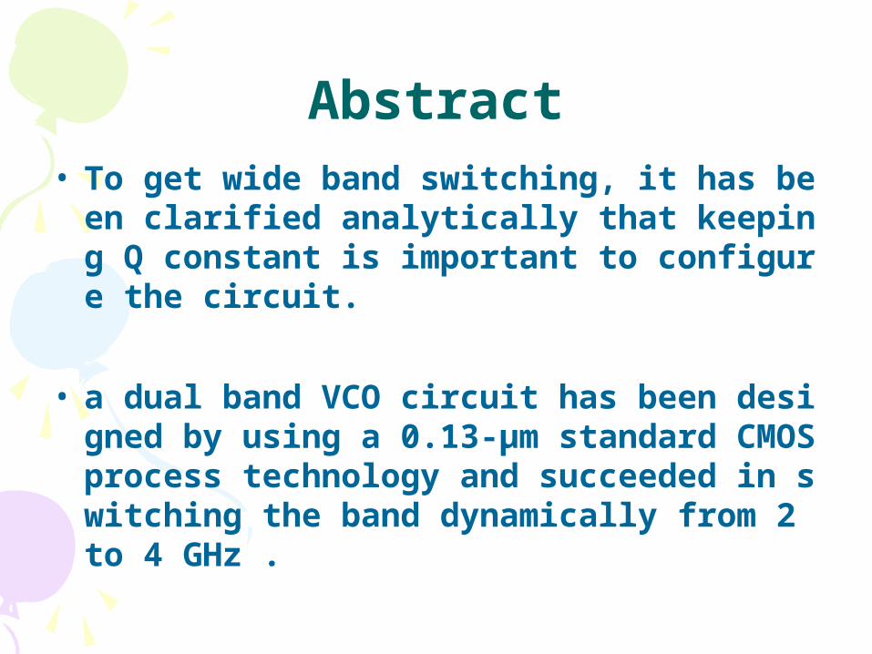
Abstract• To get wide band switching, it has been clarified a

nalytically that keeping Q constant is important to configure the circuit.

• a dual band VCO circuit has been designed by using a 0.13-μm standard CMOS process technology and succeeded in switching the band dynamically from 2 to 4 GHz .

Page 4: A Dynamic GHz-Band Switching Technique for RF CMOS VCO K, Shibata. ; H, Sato. ; N, Ishihara. ; Silicon Monolithic Integrated Circuits in RF Systems, 2007.

Introduction

• A circuit which can switch capacitors and inductors simultaneously has been suggested.

• The chip fabricated was operated with a power supply voltage of 1.7 V.

Page 5: A Dynamic GHz-Band Switching Technique for RF CMOS VCO K, Shibata. ; H, Sato. ; N, Ishihara. ; Silicon Monolithic Integrated Circuits in RF Systems, 2007.

Conventional VCOConventional VCO

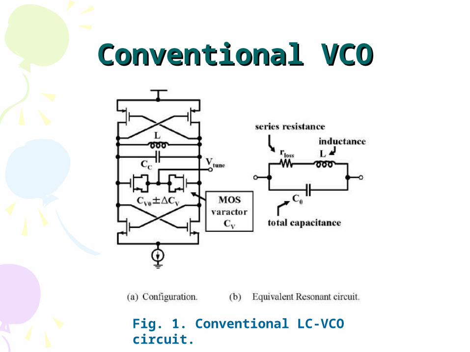
Fig. 1. Conventional LC-VCO circuit.

Page 6: A Dynamic GHz-Band Switching Technique for RF CMOS VCO K, Shibata. ; H, Sato. ; N, Ishihara. ; Silicon Monolithic Integrated Circuits in RF Systems, 2007.

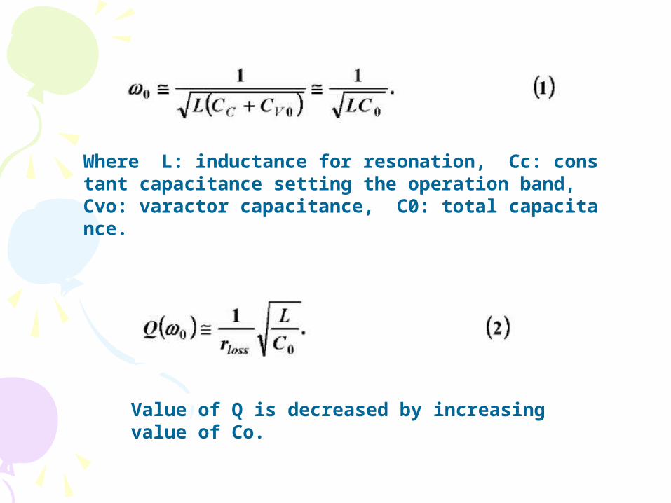
Where L: inductance for resonation, Cc: constant capacitance setting the operation band, Cvo: varactor capacitance, C0: total capacitance.

Value of Q is decreased by increasing value of Co.

Page 7: A Dynamic GHz-Band Switching Technique for RF CMOS VCO K, Shibata. ; H, Sato. ; N, Ishihara. ; Silicon Monolithic Integrated Circuits in RF Systems, 2007.

VCO circuit using simultaneous VCO circuit using simultaneous LC switching LC switching

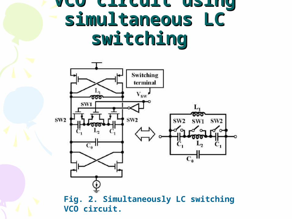
Fig. 2. Simultaneously LC switching VCO circuit.

Page 8: A Dynamic GHz-Band Switching Technique for RF CMOS VCO K, Shibata. ; H, Sato. ; N, Ishihara. ; Silicon Monolithic Integrated Circuits in RF Systems, 2007.

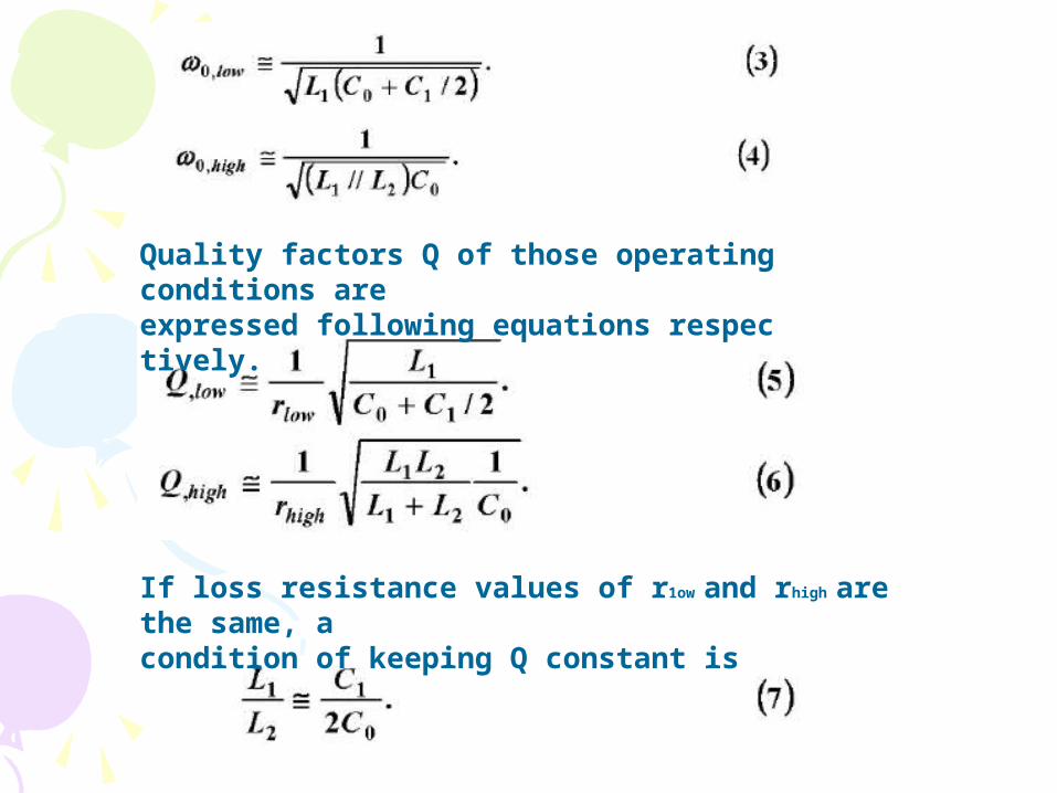
Quality factors Q of those operating conditions areexpressed following equations respectively.

If loss resistance values of r1ow and rhigh are the same, acondition of keeping Q constant is

Page 9: A Dynamic GHz-Band Switching Technique for RF CMOS VCO K, Shibata. ; H, Sato. ; N, Ishihara. ; Silicon Monolithic Integrated Circuits in RF Systems, 2007.

• Loss resistances are expressed by following equations respectively.

• If L1 is equals to L2 to simplify the discussion, a condition that r1ow becomes equal to rhigh to keep value of Q constant is

Page 10: A Dynamic GHz-Band Switching Technique for RF CMOS VCO K, Shibata. ; H, Sato. ; N, Ishihara. ; Silicon Monolithic Integrated Circuits in RF Systems, 2007.

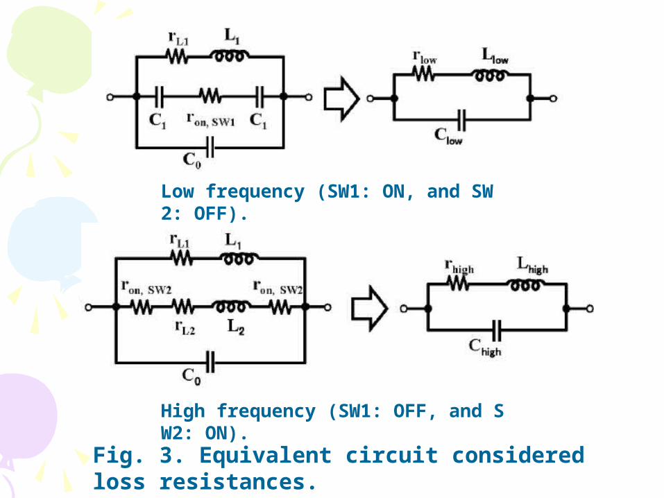
Low frequency (SW1: ON, and SW2: OFF).

High frequency (SW1: OFF, and SW2: ON).

Fig. 3. Equivalent circuit considered loss resistances.

Page 11: A Dynamic GHz-Band Switching Technique for RF CMOS VCO K, Shibata. ; H, Sato. ; N, Ishihara. ; Silicon Monolithic Integrated Circuits in RF Systems, 2007.

Fig. 4. Resonant frequency switching characteristics simulated.

Page 12: A Dynamic GHz-Band Switching Technique for RF CMOS VCO K, Shibata. ; H, Sato. ; N, Ishihara. ; Silicon Monolithic Integrated Circuits in RF Systems, 2007.

Experimental results and Experimental results and discussionsdiscussions

• Signal output buffers which can drive 50 Ω are added to the core LC-VCO circuit.

• The sizeis 1.8 mm x 1.7 mm.

• The chip packaged was measured by using a spectrum analyzer.

Page 13: A Dynamic GHz-Band Switching Technique for RF CMOS VCO K, Shibata. ; H, Sato. ; N, Ishihara. ; Silicon Monolithic Integrated Circuits in RF Systems, 2007.

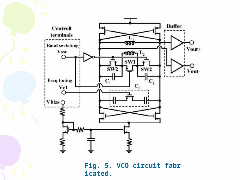
Fig. 5. VCO circuit fabricated.

Page 14: A Dynamic GHz-Band Switching Technique for RF CMOS VCO K, Shibata. ; H, Sato. ; N, Ishihara. ; Silicon Monolithic Integrated Circuits in RF Systems, 2007.

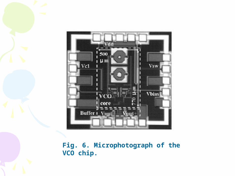
Fig. 6. Microphotograph of the VCO chip.

Page 15: A Dynamic GHz-Band Switching Technique for RF CMOS VCO K, Shibata. ; H, Sato. ; N, Ishihara. ; Silicon Monolithic Integrated Circuits in RF Systems, 2007.

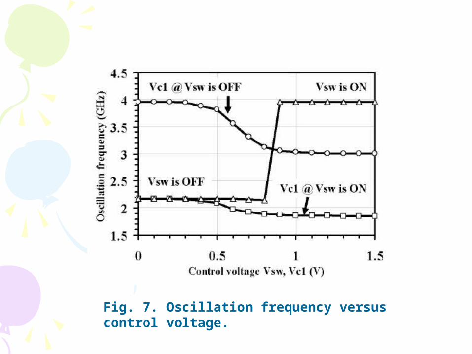
Fig. 7. Oscillation frequency versus control voltage.

Page 16: A Dynamic GHz-Band Switching Technique for RF CMOS VCO K, Shibata. ; H, Sato. ; N, Ishihara. ; Silicon Monolithic Integrated Circuits in RF Systems, 2007.

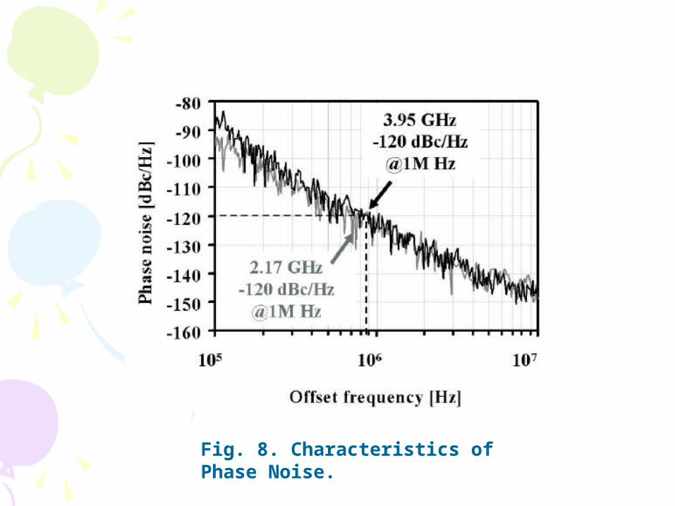
Fig. 8. Characteristics of Phase Noise.

Page 17: A Dynamic GHz-Band Switching Technique for RF CMOS VCO K, Shibata. ; H, Sato. ; N, Ishihara. ; Silicon Monolithic Integrated Circuits in RF Systems, 2007.

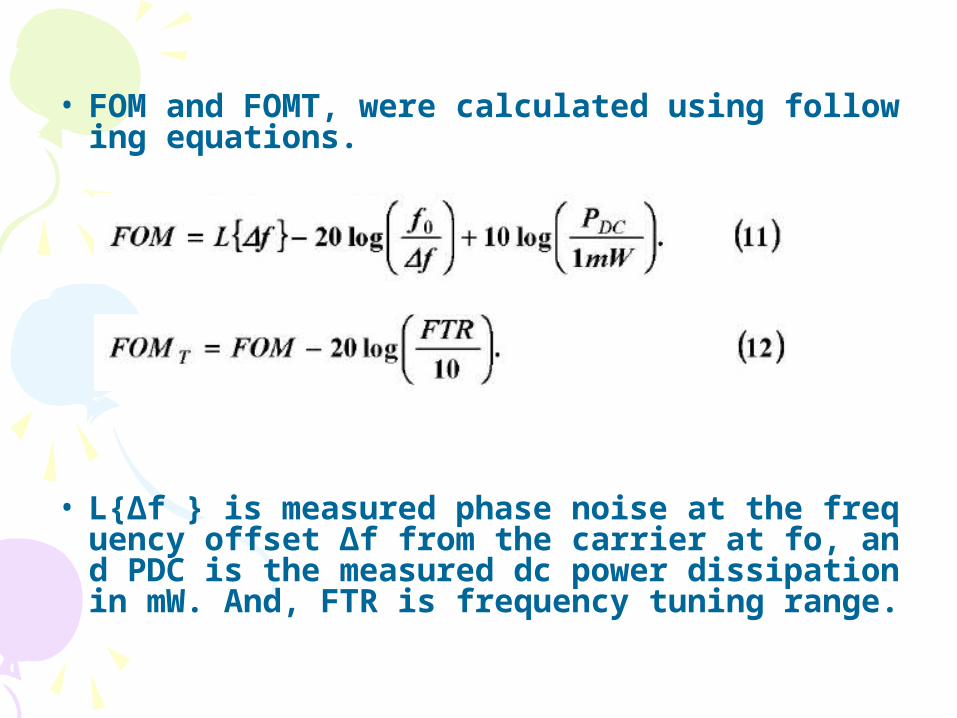
• FOM and FOMT, were calculated using following equations.

• L{Δf } is measured phase noise at the frequency offset Δf from the carrier at fo, and PDC is the measured dc power dissipation in mW. And, FTR is frequency tuning range.

Page 18: A Dynamic GHz-Band Switching Technique for RF CMOS VCO K, Shibata. ; H, Sato. ; N, Ishihara. ; Silicon Monolithic Integrated Circuits in RF Systems, 2007.

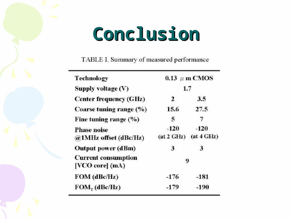
ConclusionConclusion