Dublin Institute of Technology ARROW@DIT Conference papers School of Electrical Engineering Systems 2011-05-10 A Discussion of Anti-islanding Protection Schemes Incorporated in a Inverter Based DG Mohamed Moin Hanif Dublin Institute of Technology, [email protected] Malabika Basu Dublin Institute of Technology, [email protected] Kevin Gaughan Dublin Institute of Technology, [email protected] is Conference Paper is brought to you for free and open access by the School of Electrical Engineering Systems at ARROW@DIT. It has been accepted for inclusion in Conference papers by an authorized administrator of ARROW@DIT. For more information, please contact [email protected], [email protected]. is work is licensed under a Creative Commons Aribution- Noncommercial-Share Alike 3.0 License Recommended Citation M. Hanif, M. Basu and K. Gaughan,: “A Discussion of Anti-islanding Protection Schemes Incorporated in a Inverter Based DG”, International Conference on Environment and Electrical Engineering (EEEIC) 2011, 10th International, 8-11 May 2011

Welcome message from author
This document is posted to help you gain knowledge. Please leave a comment to let me know what you think about it! Share it to your friends and learn new things together.
Transcript
Dublin Institute of TechnologyARROW@DIT
Conference papers School of Electrical Engineering Systems
2011-05-10
A Discussion of Anti-islanding Protection SchemesIncorporated in a Inverter Based DGMohamed Moin HanifDublin Institute of Technology, [email protected]
Malabika BasuDublin Institute of Technology, [email protected]
Kevin GaughanDublin Institute of Technology, [email protected]
This Conference Paper is brought to you for free and open access by theSchool of Electrical Engineering Systems at ARROW@DIT. It has beenaccepted for inclusion in Conference papers by an authorized administratorof ARROW@DIT. For more information, please [email protected], [email protected].
This work is licensed under a Creative Commons Attribution-Noncommercial-Share Alike 3.0 License
Recommended CitationM. Hanif, M. Basu and K. Gaughan,: “A Discussion of Anti-islanding Protection Schemes Incorporated in a Inverter Based DG”,International Conference on Environment and Electrical Engineering (EEEIC) 2011, 10th International, 8-11 May 2011
A Discussion of Anti-islanding Protection Schemes
Incorporated in a Inverter Based DG
M. Hanif
M. Basu, Member,IEEE
K.Gaughan
Department of Electrical Engineering Systems
Dublin Institute of Technology
Kevin Street, Dublin 8, Ireland
Abstract— The discussion in this paper is about the local anti-
islanding protection techniques that are incorporated in a
inverter based DG. The most widely used passive and active
techniques along with their suitability to reduce the on-
detection zone (DZ) are explained here. The most recent work
using wavelet transform which actually reduces the DZ to zero
is also introduced in the last section of the paper.
Keywords- Anti-islanding Schemes, Islanding Protection using
wavelet transform, on-Detection Zone
I. INTRODUCTION
Islanding of grid-connected inverters occurs when the local network containing such inverters is disconnected from the main utility, but the inverters continue energizing the local load without control and/or supervision of utility. This phenomenon can result in a number of potential hazards and therefore needs to be detected and protected from islanding.
Basic passive protection schemes include over current, over- and under-voltage, and over- and under-frequency (OV/UV and OF/UF) functions to remove a grid connected inverter from the utility grid for the abnormal condition in the grid. Also, anti-islanding schemes must be incorporated into protection control. The above OV/UV/OF/UF schemes are able to detect islanding operation of the grid connected inverter.
In case of DG, however, inverter generation being balanced with local load, it is impossible to detect the formation of island with the basic passive schemes creating a NDZ. Therefore passive detection methods on its own are not sufficient for anti islanding protection hence at least one active anti-islanding scheme must be included in protection (to eliminate NDZ).
Active islanding scheme usually injects certain signals (perturbation to variables like voltage and frequency) in order to detect the islanding situation which degrades the output power quality.
In response to the above mentioned problem, a detailed literature survey is conducted and the paper discusses the present islanding detection schemes which can be classified as passive, active and other methods.
Other methods include: Reactance Insertion, Power Line Carrier Communication and Supervisory Control & Data Acquisition methods. These methods are implemented at utility level and since they are beyond the scope of this paper (the
inverter to be built needs its own protection against islanding according to the standards) they will not be discussed.
The islanding schemes below are discussed in terms of their
capability to reduce the NDZ, significant strengths and
weaknesses.
II. PASSIVE METHODS
A. Under/over Voltage and Under/over Frequency Detection
In over/under voltage and over/under frequency detection,
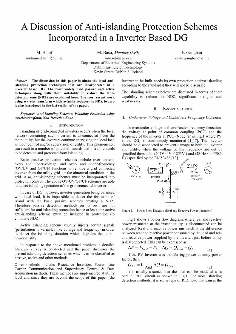
the voltage at point of common coupling (PCC) and the frequency of the inverter at PCC (Node ‘a’ in Fig.1 where PV is the DG) is continuously monitored [1-17]. The inverter should be disconnected to prevent damage to both the inverter and utility, when the voltage or the frequency are out of specified thresholds (207V ≤ V ≤ 253V ) and (48 Hz ≤ f ≤50.5 Hz) specified by the EN 50438 [13].
Figure 1. Power Flow Diagram (Real and Reactive Power mismatch)
Fig.1 shows a power flow diagram, where real and reactive
power mismatch at the instant utility is disconnected can be
analyzed. Real and reactive power mismatch is the difference
between real and reactive power consumed by the load and real
and reactive power supplied by the inverter, just before utility
is disconnected. This can be expressed as:
PVLoad PPP −=∆, PVLoad QQQ −=∆
(1)
If the PV Inverter was transferring power at unity power
factor, then
0=PVQ And LoadQQ =∆
(2) It is usually assumed that the load can be modeled as a
parallel RLC circuit as shown in Fig.1. For most islanding detection methods, it is some type of RLC load that causes the
most difficulty in detection. General nonlinear loads such as harmonic-producing loads or constant-power loads do not exhibit as much difficulty in islanding prevention.
RLC loads with a high q (Quality factor) are most problematic for islanding detection. The quality factor can be expressed as:
L
CRq =
(3) Parameters R, L and C give the relative amounts of energy storage and energy dissipation.
Real and reactive power of the load can be expressed as:
R
VP PVLoad
2
=,
)1
(2
CL
VQ PVLoad ωω
−= (4)
Real and Reactive power supplied by the PV Inverter can be
expressed as:
θCosIVP PVPVPV = , θSinIVQ PVPVPV = (5)
Where VPV and IPV are RMS values and Cosθ is the power
factor
From [3, 12 and 18] it can be noted, at instant when island is formed (utility is disconnected), the system behavior depends on ∆P and ∆Q as follows:
(∆P>0): The inverter terminal voltage will increase above the nominal system voltage.
(∆P<0): The inverter terminal voltage will decrease below the nominal system voltage.
(∆Q>0): The frequency will increase until reactive power supplied by the capacitor C balances with that consumed by the inductor L.
(∆Q<0): The frequency will decrease below nominal system frequency.
Generally the power mismatches are large (∆P > ±20% or ∆Q > ±5%), causing the voltage or frequency to go out of the nominal range detecting islanding. But if the mismatch is quite small leaving the voltage and frequency within the nominal range would make the islanding detection impossible causing a large non detection zone (NDZ). Also, if the threshold range is set small, nuisance tripping could occur, hence this detection method on its on is not sufficient for anti islanding protection [1-15].
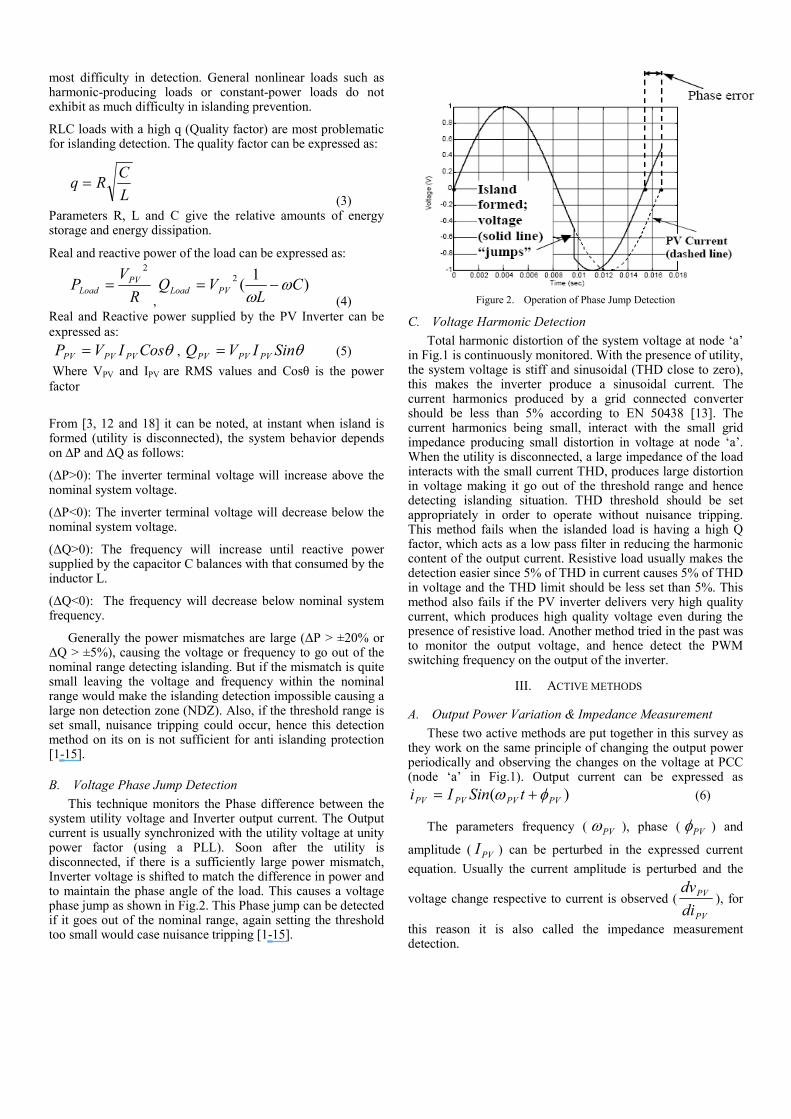
B. Voltage Phase Jump Detection
This technique monitors the Phase difference between the system utility voltage and Inverter output current. The Output current is usually synchronized with the utility voltage at unity power factor (using a PLL). Soon after the utility is disconnected, if there is a sufficiently large power mismatch, Inverter voltage is shifted to match the difference in power and to maintain the phase angle of the load. This causes a voltage phase jump as shown in Fig.2. This Phase jump can be detected if it goes out of the nominal range, again setting the threshold too small would case nuisance tripping [1-15].
Figure 2. Operation of Phase Jump Detection
C. Voltage Harmonic Detection
Total harmonic distortion of the system voltage at node ‘a’ in Fig.1 is continuously monitored. With the presence of utility, the system voltage is stiff and sinusoidal (THD close to zero), this makes the inverter produce a sinusoidal current. The current harmonics produced by a grid connected converter should be less than 5% according to EN 50438 [13]. The current harmonics being small, interact with the small grid impedance producing small distortion in voltage at node ‘a’. When the utility is disconnected, a large impedance of the load interacts with the small current THD, produces large distortion in voltage making it go out of the threshold range and hence detecting islanding situation. THD threshold should be set appropriately in order to operate without nuisance tripping. This method fails when the islanded load is having a high Q factor, which acts as a low pass filter in reducing the harmonic content of the output current. Resistive load usually makes the detection easier since 5% of THD in current causes 5% of THD in voltage and the THD limit should be less set than 5%. This method also fails if the PV inverter delivers very high quality current, which produces high quality voltage even during the presence of resistive load. Another method tried in the past was to monitor the output voltage, and hence detect the PWM switching frequency on the output of the inverter.
III. ACTIVE METHODS
A. Output Power Variation & Impedance Measurement
These two active methods are put together in this survey as they work on the same principle of changing the output power periodically and observing the changes on the voltage at PCC (node ‘a’ in Fig.1). Output current can be expressed as
)( PVPVPVPV tSinIi φω += (6)
The parameters frequency ( PVω ), phase ( PVφ ) and
amplitude ( PVI ) can be perturbed in the expressed current
equation. Usually the current amplitude is perturbed and the
voltage change respective to current is observed (
PV
PV
di
dv), for
this reason it is also called the impedance measurement detection.
Impedance measurement: If impedance is observed specifically rather than the output voltage, then a threshold for impedance needs to be set, a small value since the grid impedance is not exactly zero. Any impedance observed below the set value indicates grid is still connected unless the impedance of the load is below the set point which is very rare unless the load is a high power load (approaching a short circuit)
Output power variation: Change in current amplitude ( PVI )
causes a change in output power. Change in current or power causes a change in voltage at PCC, which when islanded shows a significant change and gets out of the nominal threshold range. This behavior can be used to detect the islanded situation.
The minimum current shift required for islanding detection is equal to the full UVP/ OVP (Under Voltage Protection/ Over Voltage Protection) window size. For instance, with grid connected UVP/OVP at +/-10% of rated voltage, a 20% change in current is required.
This method works quite well with a single grid connected inverter reducing the NDZ close to zero, but fails with multiple inverters connected. When multiple inverters are connected, change in current from one inverter is not significant and effectiveness of this method decreases, unless the variation from all the inverters is some how synchronized (which degrades the power quality greatly) [1-15].
B. Sliding Mode Frequency Shift (SMS)
The three parameters of the voltage at node ‘a’ in Fig.1, to which positive feedback can be applied are amplitude, frequency, and phase. SMS applies positive feedback to the phase of the voltage at PCC (to the reference waveform in practical implementation) as a method to shift the phase.
The phase angle between the inverter output current and the PCC voltage is controlled to be zero (or as close to it as possible) usually in a PV inverter (unity power factor operation). But with SMS applied, the current-voltage phase angle of the inverter is made to be a function of the frequency of the PCC voltage, instead of being controlled to zero.
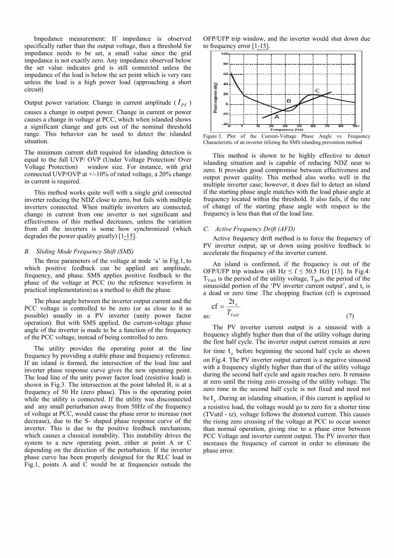
The utility provides the operating point at the line frequency by providing a stable phase and frequency reference. If an island is formed, the intersection of the load line and inverter phase response curve gives the new operating point. The load line of the unity power factor load (resistive load) is shown in Fig.3. The intersection at the point labeled B, is at a frequency of 50 Hz (zero phase). This is the operating point while the utility is connected. If the utility was disconnected and any small perturbation away from 50Hz of the frequency of voltage at PCC, would cause the phase error to increase (not decrease), due to the S- shaped phase response curve of the inverter. This is due to the positive feedback mechanism, which causes a classical instability. This instability drives the system to a new operating point, either at point A or C depending on the direction of the perturbation. If the inverter phase curve has been properly designed for the RLC load in Fig.1, points A and C would be at frequencies outside the
OFP/UFP trip window, and the inverter would shut down due to frequency error [1-15].
Figure 3. Plot of the Current-Voltage Phase Angle vs. Frequency
Characteristic of an inverter itilizing the SMS islanding prevention method
This method is shown to be highly effective to detect islanding situation and is capable of reducing NDZ near to zero. It provides good compromise between effectiveness and output power quality. This method also works well in the multiple inverter case; however, it does fail to detect an island if the starting phase angle matches with the load phase angle at frequency located within the threshold. It also fails, if the rate of change of the starting phase angle with respect to the frequency is less than that of the load line.
C. Active Frequency Drift (AFD)
Active frequency drift method is to force the frequency of PV inverter output, up or down using positive feedback to accelerate the frequency of the inverter current.
An island is confirmed, if the frequency is out of the OFP/UFP trip window (48 Hz ≤ f ≤ 50.5 Hz) [13]. In Fig.4: TVutil is the period of the utility voltage, TIpvis the period of the sinusoidal portion of the ‘PV inverter current output’, and tz is a dead or zero time .The chopping fraction (cf) is expressed
as: VutilT
z2tcf =
(7)
The PV inverter current output is a sinusoid with a frequency slightly higher than that of the utility voltage during the first half cycle. The inverter output current remains at zero
for time zt before beginning the second half cycle as shown
on Fig.4. The PV inverter output current is a negative sinusoid with a frequency slightly higher than that of the utility voltage during the second half cycle and again reaches zero. It remains at zero until the rising zero crossing of the utility voltage. The zero time in the second half cycle is not fixed and need not
be zt .During an islanding situation, if this current is applied to
a resistive load, the voltage would go to zero for a shorter time (TVutil - tz), voltage follows the distorted current. This causes the rising zero crossing of the voltage at PCC to occur sooner than normal operation, giving rise to a phase error between PCC Voltage and inverter current output. The PV inverter then increases the frequency of current in order to eliminate the phase error.
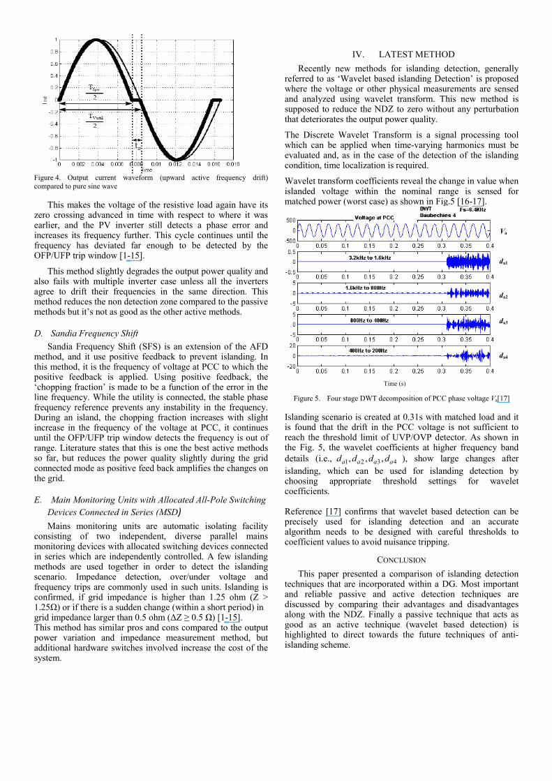
Figure 4. Output current waveform (upward active frequency drift)
compared to pure sine wave
This makes the voltage of the resistive load again have its zero crossing advanced in time with respect to where it was earlier, and the PV inverter still detects a phase error and increases its frequency further. This cycle continues until the frequency has deviated far enough to be detected by the OFP/UFP trip window [1-15].
This method slightly degrades the output power quality and also fails with multiple inverter case unless all the inverters agree to drift their frequencies in the same direction. This method reduces the non detection zone compared to the passive methods but it’s not as good as the other active methods.
D. Sandia Frequency Shift
Sandia Frequency Shift (SFS) is an extension of the AFD method, and it use positive feedback to prevent islanding. In this method, it is the frequency of voltage at PCC to which the positive feedback is applied. Using positive feedback, the ‘chopping fraction’ is made to be a function of the error in the line frequency. While the utility is connected, the stable phase frequency reference prevents any instability in the frequency. During an island, the chopping fraction increases with slight increase in the frequency of the voltage at PCC, it continues until the OFP/UFP trip window detects the frequency is out of range. Literature states that this is one the best active methods so far, but reduces the power quality slightly during the grid connected mode as positive feed back amplifies the changes on the grid.
E. Main Monitoring Units with Allocated All-Pole Switching
Devices Connected in Series (MSD)
Mains monitoring units are automatic isolating facility consisting of two independent, diverse parallel mains monitoring devices with allocated switching devices connected in series which are independently controlled. A few islanding methods are used together in order to detect the islanding scenario. Impedance detection, over/under voltage and frequency trips are commonly used in such units. Islanding is confirmed, if grid impedance is higher than 1.25 ohm (Z > 1.25Ω) or if there is a sudden change (within a short period) in grid impedance larger than 0.5 ohm (∆Z ≥ 0.5 Ω) [1-15]. This method has similar pros and cons compared to the output power variation and impedance measurement method, but additional hardware switches involved increase the cost of the system.
IV. LATEST METHOD
Recently new methods for islanding detection, generally referred to as ‘Wavelet based islanding Detection’ is proposed where the voltage or other physical measurements are sensed and analyzed using wavelet transform. This new method is supposed to reduce the NDZ to zero without any perturbation that deteriorates the output power quality.
The Discrete Wavelet Transform is a signal processing tool which can be applied when time-varying harmonics must be evaluated and, as in the case of the detection of the islanding condition, time localization is required.
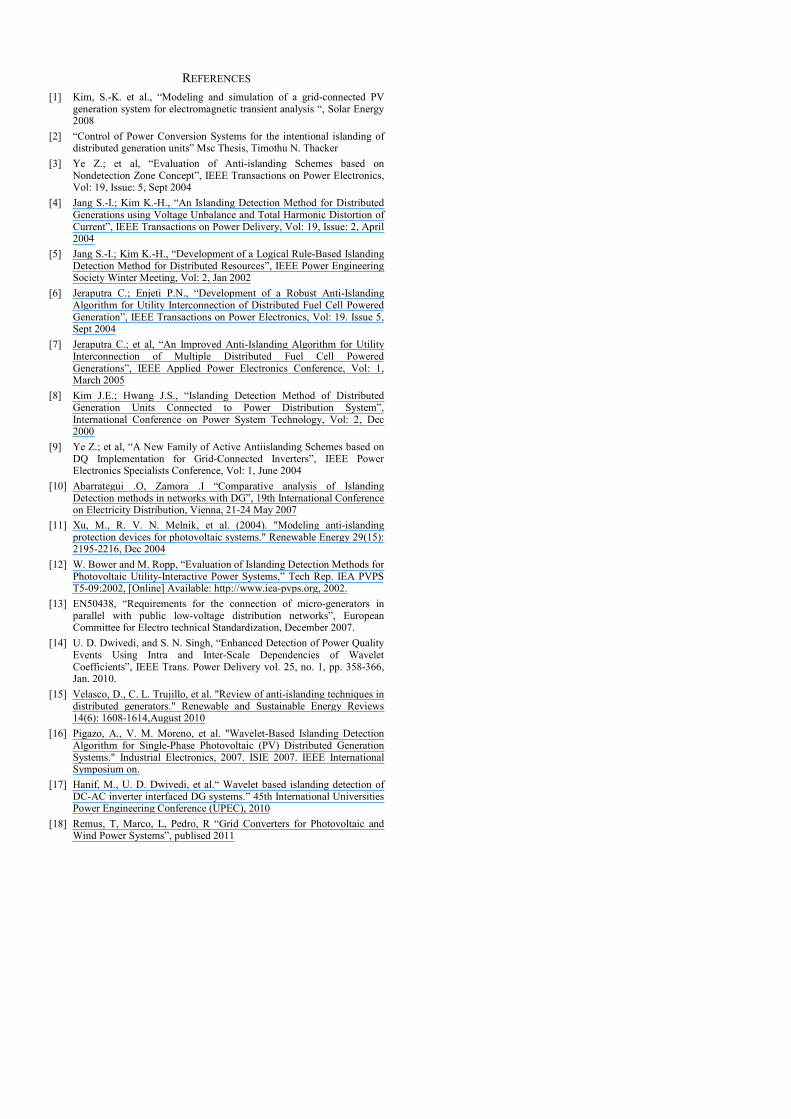
Wavelet transform coefficients reveal the change in value when islanded voltage within the nominal range is sensed for matched power (worst case) as shown in Fig.5 [16-17].
Figure 5. Four stage DWT decomposition of PCC phase voltage Va[17]
Islanding scenario is created at 0.31s with matched load and it is found that the drift in the PCC voltage is not sufficient to reach the threshold limit of UVP/OVP detector. As shown in the Fig. 5, the wavelet coefficients at higher frequency band
details (i.e., 1 2 3 4, , ,a a a ad d d d ), show large changes after
islanding, which can be used for islanding detection by choosing appropriate threshold settings for wavelet coefficients. Reference [17] confirms that wavelet based detection can be precisely used for islanding detection and an accurate algorithm needs to be designed with careful thresholds to coefficient values to avoid nuisance tripping.
CONCLUSION
This paper presented a comparison of islanding detection techniques that are incorporated within a DG. Most important and reliable passive and active detection techniques are discussed by comparing their advantages and disadvantages along with the NDZ. Finally a passive technique that acts as good as an active technique (wavelet based detection) is highlighted to direct towards the future techniques of anti-islanding scheme.
Va
da1
da2
da3
da4
Time (s)
REFERENCES
[1] Kim, S.-K. et al., “Modeling and simulation of a grid-connected PV generation system for electromagnetic transient analysis “, Solar Energy 2008
[2] “Control of Power Conversion Systems for the intentional islanding of distributed generation units” Msc Thesis, Timothu N. Thacker
[3] Ye Z.; et al, “Evaluation of Anti-islanding Schemes based on Nondetection Zone Concept”, IEEE Transactions on Power Electronics, Vol: 19, Issue: 5, Sept 2004
[4] Jang S.-I.; Kim K.-H., “An Islanding Detection Method for Distributed Generations using Voltage Unbalance and Total Harmonic Distortion of Current”, IEEE Transactions on Power Delivery, Vol: 19, Issue: 2, April 2004
[5] Jang S.-I.; Kim K.-H., “Development of a Logical Rule-Based Islanding Detection Method for Distributed Resources”, IEEE Power Engineering Society Winter Meeting, Vol: 2, Jan 2002
[6] Jeraputra C.; Enjeti P.N., “Development of a Robust Anti-Islanding Algorithm for Utility Interconnection of Distributed Fuel Cell Powered Generation”, IEEE Transactions on Power Electronics, Vol: 19. Issue 5, Sept 2004
[7] Jeraputra C.; et al, “An Improved Anti-Islanding Algorithm for Utility Interconnection of Multiple Distributed Fuel Cell Powered Generations”, IEEE Applied Power Electronics Conference, Vol: 1, March 2005
[8] Kim J.E.; Hwang J.S., “Islanding Detection Method of Distributed Generation Units Connected to Power Distribution System”, International Conference on Power System Technology, Vol: 2, Dec 2000
[9] Ye Z.; et al, “A New Family of Active Antiislanding Schemes based on DQ Implementation for Grid-Connected Inverters”, IEEE Power Electronics Specialists Conference, Vol: 1, June 2004
[10] Abarrategui .O, Zamora .I “Comparative analysis of Islanding Detection methods in networks with DG”, 19th International Conference on Electricity Distribution, Vienna, 21-24 May 2007
[11] Xu, M., R. V. N. Melnik, et al. (2004). "Modeling anti-islanding protection devices for photovoltaic systems." Renewable Energy 29(15): 2195-2216, Dec 2004
[12] W. Bower and M. Ropp, “Evaluation of Islanding Detection Methods for Photovoltaic Utility-Interactive Power Systems,” Tech Rep. IEA PVPS T5-09:2002, [Online] Available: http://www.iea-pvps.org, 2002.
[13] EN50438, “Requirements for the connection of micro-generators in parallel with public low-voltage distribution networks”, European Committee for Electro technical Standardization, December 2007.
[14] U. D. Dwivedi, and S. N. Singh, “Enhanced Detection of Power Quality Events Using Intra and Inter-Scale Dependencies of Wavelet Coefficients”, IEEE Trans. Power Delivery vol. 25, no. 1, pp. 358-366, Jan. 2010.
[15] Velasco, D., C. L. Trujillo, et al. "Review of anti-islanding techniques in distributed generators." Renewable and Sustainable Energy Reviews 14(6): 1608-1614,August 2010
[16] Pigazo, A., V. M. Moreno, et al. "Wavelet-Based Islanding Detection Algorithm for Single-Phase Photovoltaic (PV) Distributed Generation Systems." Industrial Electronics, 2007. ISIE 2007. IEEE International Symposium on.
[17] Hanif, M., U. D. Dwivedi, et al.“ Wavelet based islanding detection of DC-AC inverter interfaced DG systems.” 45th International Universities Power Engineering Conference (UPEC), 2010
[18] Remus, T, Marco, L, Pedro, R “Grid Converters for Photovoltaic and Wind Power Systems”, publised 2011
Related Documents


![SMART GRID ISLANDING, FAULT DETECTION AND …€¦ · Narayana presented a scheme on a priority based load shedding to detect islanding in case of multiple DG units [15].Ahmad G.](https://static.cupdf.com/doc/110x72/5ea3dfb794b1c3448357d81b/smart-grid-islanding-fault-detection-and-narayana-presented-a-scheme-on-a-priority.jpg)