A Design Procedure for Control Systems of Inverter- based DG in Microgrids Toshihisa Funabashi, Shota Igarashi, Yusuke Manabe, Muneaki Kurimoto, Takeyoshi Kato Abstract-- In constructing microgrids with only inverter-based DGs, fast transient response and robust stability are required in inverter control system. However, it is difficult to design a control system of the inverter with those abilities because of non-linearity of inverter control system and loads in microgrids. This paper studies a design method for an inverter control system of a microgrid at an isolated mode. Keywords: microgrid, isolated operation, inverter, PI controller, stability. I. INTRODUCTION n electrification of a remote area such as remote islands and rural villages, it is necessary to construct autonomous systems. In such places, implementation of an isolated microgrid, a network of generators and loads, is assumed. Conventionally, the autonomous system was constructed using rotary machines such as diesel generators. In recent years, due to the high penetration of renewable energy sources into power systems, microgrids can be constructed with only inverter- based distributed generations (DGs). However, because microgrids are small systems, it is difficult to maintain voltage and frequency within a proper range and to suppress harmonics in microgrids at isolated operation, when a disturbance occurs [1], [2]. Furthermore, in microgrids composed with only inverter-based DGs, these problems become more serious since there are no rotating machines with inertia. In constructing microgrids, fast transient response, reference following characteristic and robust stability are required in inverter control systems to solve these problems. Simulation and verification tests of microgrids with only inverter-based DGs at isolated operation have been performed [3], [4]. Parameters of control systems in previous approaches have been determined by trial and error using simulation tool. Otherwise, inverter output current has been regarded as disturbance and parameters have been designed to suppress the influence of the disturbance in individual inverters [5], [6]. However, control systems are designed without considering whole microgrids including controller performance in isolated operation. Therefore, they might have been underestimated. Furthermore, to design control systems considering whole microgrids, it is necessary to represent nonlinear plant models such as DGs and nonlinear loads in microgrids by a transfer function or a state-space function. By linearization of these components, controllers can be designed to have a performance We would like to thank grant for Environmental Research Projects from The Sumitomo Foundation. Toshihisa Funabashi, Shota Igarashi, Yusuke Manabe, Muneaki Kurimoto, and Takeyoshi Kato are with Nagoya University, Chikusa-ku, Nagoya city, Japan (e-mail: [email protected]). of fast response and robust stability near an operating point. However, in above method, it is difficult to linearize all control targets properly. In this paper, system identification of the plant model for a microgrid including only inverter-based DGs was performed using perturbation signals. An inverter control system was designed considering the whole microgrid. Concrete design procedures are as follows. (1) The microgrid was modeled using XTAP (eXpandable Transient Analysis Program) [7]. (2) A Bode diagram of the non-linear plant model was calculated by adding a perturbation signal to a voltage reference of the inverter control system. (3) The plant model was identified from the Bode diagram and a controller in the inverter control system was designed using MATLAB. (4) Controller performance was confirmed by simulation using XTAP. The validity of this design method is confirmed by transient simulations with both designed control systems by the proposed method and by the conventional method. II. MICROGRID MODEL The microgrid model in this paper includes an Energy Storage System (ESS) rated 150kVA, a Photovoltaic System (PVS) rated 100kW and an RL load rated 50kW (PF=0.8). Fig. 1 shows a single-line layout of the microgrid system and Table 1 shows main parameters values of microgrid components. The ESS is a voltage-control-type storage system and it controls voltage and frequency in the microgrid. The PVS is a current- control-type generation system and it generates active/reactive power output. RMS(Rated Mean Square) voltage and frequency in the microgrid are 6600V and 60Hz respectively. Details of each component in the microgrid are as follows. A. ESS A Battery energy storage system is presented by the DC voltage source. It is interconnected to the PCC (Point of Common Coupling) through an inverter, a transformer, and a filter. Fig. 2 shows the control system of the ESS. Where, ref V is voltage reference (1 p.u.), V is inverter output RMS line voltage which is calculated by (1) using dq transformation and m is modulation signal. Frequency is fixed at 60Hz. Paper submitted to the International Conference on Power Systems Transients (IPST2017) in Seoul, Republic of Korea June 26-29, 2017 I

Welcome message from author
This document is posted to help you gain knowledge. Please leave a comment to let me know what you think about it! Share it to your friends and learn new things together.
Transcript

A Design Procedure for Control Systems of Inverter-based DG in Microgrids
Toshihisa Funabashi, Shota Igarashi, Yusuke Manabe, Muneaki Kurimoto, Takeyoshi Kato
Abstract-- In constructing microgrids with only inverter-based
DGs, fast transient response and robust stability are required in inverter control system. However, it is difficult to design a control system of the inverter with those abilities because of non-linearity of inverter control system and loads in microgrids. This paper studies a design method for an inverter control system of a microgrid at an isolated mode.
Keywords: microgrid, isolated operation, inverter, PI
controller, stability.
I. INTRODUCTION n electrification of a remote area such as remote islands and rural villages, it is necessary to construct autonomous
systems. In such places, implementation of an isolated microgrid, a network of generators and loads, is assumed. Conventionally, the autonomous system was constructed using rotary machines such as diesel generators. In recent years, due to the high penetration of renewable energy sources into power systems, microgrids can be constructed with only inverter-based distributed generations (DGs).
However, because microgrids are small systems, it is difficult to maintain voltage and frequency within a proper range and to suppress harmonics in microgrids at isolated operation, when a disturbance occurs [1], [2]. Furthermore, in microgrids composed with only inverter-based DGs, these problems become more serious since there are no rotating machines with inertia. In constructing microgrids, fast transient response, reference following characteristic and robust stability are required in inverter control systems to solve these problems.
Simulation and verification tests of microgrids with only inverter-based DGs at isolated operation have been performed [3], [4]. Parameters of control systems in previous approaches have been determined by trial and error using simulation tool. Otherwise, inverter output current has been regarded as disturbance and parameters have been designed to suppress the influence of the disturbance in individual inverters [5], [6]. However, control systems are designed without considering whole microgrids including controller performance in isolated operation. Therefore, they might have been underestimated. Furthermore, to design control systems considering whole microgrids, it is necessary to represent nonlinear plant models such as DGs and nonlinear loads in microgrids by a transfer function or a state-space function. By linearization of these components, controllers can be designed to have a performance
We would like to thank grant for Environmental Research Projects from The Sumitomo Foundation. Toshihisa Funabashi, Shota Igarashi, Yusuke Manabe, Muneaki Kurimoto, and Takeyoshi Kato are with Nagoya University, Chikusa-ku, Nagoya city, Japan (e-mail: [email protected]).
of fast response and robust stability near an operating point. However, in above method, it is difficult to linearize all control targets properly.
In this paper, system identification of the plant model for a microgrid including only inverter-based DGs was performed using perturbation signals. An inverter control system was designed considering the whole microgrid. Concrete design procedures are as follows. (1) The microgrid was modeled using XTAP (eXpandable Transient Analysis Program) [7]. (2) A Bode diagram of the non-linear plant model was calculated by adding a perturbation signal to a voltage reference of the inverter control system. (3) The plant model was identified from the Bode diagram and a controller in the inverter control system was designed using MATLAB. (4) Controller performance was confirmed by simulation using XTAP.
The validity of this design method is confirmed by transient simulations with both designed control systems by the proposed method and by the conventional method.
II. MICROGRID MODEL The microgrid model in this paper includes an Energy
Storage System (ESS) rated 150kVA, a Photovoltaic System (PVS) rated 100kW and an RL load rated 50kW (PF=0.8). Fig. 1 shows a single-line layout of the microgrid system and Table 1 shows main parameters values of microgrid components. The ESS is a voltage-control-type storage system and it controls voltage and frequency in the microgrid. The PVS is a current-control-type generation system and it generates active/reactive power output. RMS(Rated Mean Square) voltage and frequency in the microgrid are 6600V and 60Hz respectively. Details of each component in the microgrid are as follows.
A. ESS A Battery energy storage system is presented by the DC
voltage source. It is interconnected to the PCC (Point of Common Coupling) through an inverter, a transformer, and a filter. Fig. 2 shows the control system of the ESS. Where, refV is voltage reference (1 p.u.), V is inverter output RMS line voltage which is calculated by (1) using dq transformation and m is modulation signal. Frequency is fixed at 60Hz.
Paper submitted to the International Conference on Power Systems Transients (IPST2017) in Seoul, Republic of Korea June 26-29, 2017
I
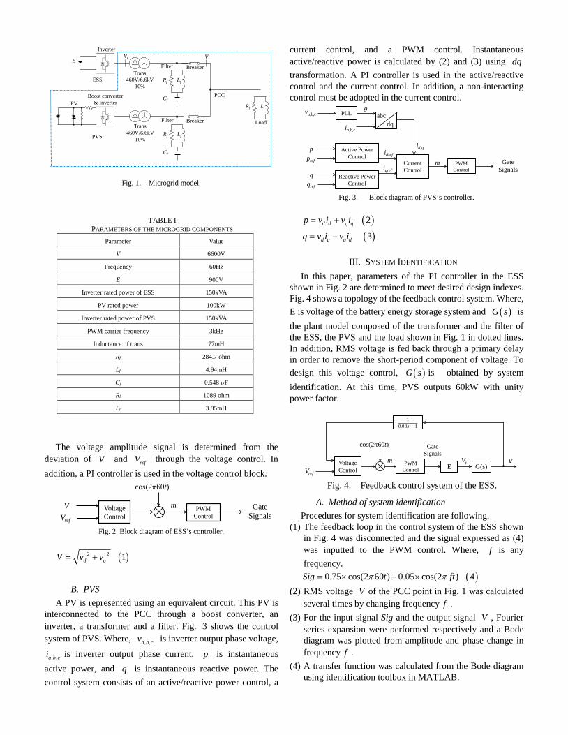
Fig. 1. Microgrid model.
The voltage amplitude signal is determined from the
deviation of V and refV through the voltage control. In addition, a PI controller is used in the voltage control block.
Fig. 2. Block diagram of ESS’s controller.
( )2 2 1d qV v v= +
B. PVS A PV is represented using an equivalent circuit. This PV is
interconnected to the PCC through a boost converter, an inverter, a transformer and a filter. Fig. 3 shows the control system of PVS. Where, , ,a b cv is inverter output phase voltage,
, ,a b ci is inverter output phase current, p is instantaneous active power, and q is instantaneous reactive power. The control system consists of an active/reactive power control, a
current control, and a PWM control. Instantaneous active/reactive power is calculated by (2) and (3) using dq transformation. A PI controller is used in the active/reactive control and the current control. In addition, a non-interacting control must be adopted in the current control.
Fig. 3. Block diagram of PVS’s controller.
( )2d d q qp v i v i= +
( )3d q q dq v i v i= −
III. SYSTEM IDENTIFICATION In this paper, parameters of the PI controller in the ESS
shown in Fig. 2 are determined to meet desired design indexes. Fig. 4 shows a topology of the feedback control system. Where, E is voltage of the battery energy storage system and ( )G s is the plant model composed of the transformer and the filter of the ESS, the PVS and the load shown in Fig. 1 in dotted lines. In addition, RMS voltage is fed back through a primary delay in order to remove the short-period component of voltage. To design this voltage control, ( )G s is obtained by system identification. At this time, PVS outputs 60kW with unity power factor.
Fig. 4. Feedback control system of the ESS.
A. Method of system identification Procedures for system identification are following.
(1) The feedback loop in the control system of the ESS shown in Fig. 4 was disconnected and the signal expressed as (4) was inputted to the PWM control. Where, f is any frequency.
( )0.75 cos(2 60 ) 0.05 cos(2 ) 4Sig t ftπ π= × + × (2) RMS voltage V of the PCC point in Fig. 1 was calculated
several times by changing frequency f . (3) For the input signal Sig and the output signal V , Fourier
series expansion were performed respectively and a Bode diagram was plotted from amplitude and phase change in frequency f .
(4) A transfer function was calculated from the Bode diagram using identification toolbox in MATLAB.
Inverter
ESS
Filter
Lf
Cf
Rf
Load
Rl Ll
E
Trans460V/6.6kV
10%
PV
Filter
Lf
Cf
Rf
Trans460V/6.6kV
10%
Breaker
Breaker
Boost converter& Inverter
PVS
PCC
Vt V
VoltageControl
VVref
cos(2π60t)
PWMControl
Gate Signals
m
PLL
CurrentControl
PWMControl
Active PowerControl
Reactive PowerControl
pref
p
qref
q
va,b,c
ia,b,c
θabc
dq
id,q
Gate Signals
idref
iqrefm
VoltageControl
VVref
cos(2π60t)
PWMControl
Gate Signals
G(s)EVtm
TABLE I
PARAMETERS OF THE MICROGRID COMPONENTS Parameter Value
V 6600V
Frequency 60Hz
E 900V
Inverter rated power of ESS 150kVA
PV rated power 100kW
Inverter rated power of PVS 150kVA
PWM carrier frequency 3kHz
Inductance of trans 77mH
Rf 284.7 ohm
Lf 4.94mH
Cf 0.548 υF
Rl 1089 ohm
Ll 3.85mH

B. Identification results The plant model ( )G s was identified as the third-order
transfer function from simulation results and expressed as (5). Fig. 5 shows the Bode diagram of the identified model of (5) and simulation results of above step (3). Fit rate expressed as (6) was 68%. Where, ( )y k is the Bode diagram of simulation results, avey is its average and ( )my k is the Bode diagram of
( )G s . However, those were consistent in medium-frequency
from 100rad/sw = to 6000rad/s . Therefore, the controller can be designed using this plant model ( )G s .
( )3 2 6 10
3 3 2 7 10
2.62 10 9.62 10 6.15 10( ) 55.68 10 1.76 10 6.33 10
s sG ss s s
× + × + ×=
+ × + × + ×
a. Gain diagram.
b. Phase diagram.
Fig. 5. Bode diagram of the plant model.
( )
2
1
2
1
[ ( ) ( )]1 100 6
[ ( ) ]
N
mk
N
avek
y k y kFit
y k y
=
=
− = − × −
∑
∑
IV. CONTROLLER DESIGN The controller of ESS’s inverter is designed using the plant
model ( )G s so that the control system has quick response time reference following characteristic and robust stability.
They are design indexes. Robust stability is to keep stability even if parameters of the plant model ( )G s change by PVS output fluctuation or load fluctuation. In addition, the controller is designed using SISO design tool in MATLAB.
A. Sensitivity analysis for robust stability design A plant model is represented by a set of models expressed in
(7). Where, ( )s∆ is a stable transfer function which
represents the uncertainty of the model and ( )nG s is nominal model and it is assumed as (5) in this paper. A weighting function ( )W s , which satisfies (8), is decided by performing a sensitivity analysis to represent the nominal model as a set of models. Furthermore, a control system has a robust stability if it satisfied (9). Where, ( )C s is a controller.
( ) ( )~
( ) 1 ( ) ( ) 7nG s s G s= + ∆
( )( ) ( ) 8j W jω ω∆ ≤
( )( ) ( ) ( )1, 9
1 ( ) ( )n
n
W j C j G jC j G jω ω ω
ωω ω
< ∀+
The plant model ( )G s changes according to load and PVS
output state in the microgrid. Therefore, the variation of the Bode diagram is examined by performing sensitivity analysis shown in Table II. The Bode diagrams are calculated in the same way as section Ⅲ.
Fig. 6 shows the Bode diagram of sensitivity analysis results.
From Fig. 6, it can be seen that an impact, that PVS output gave to the nominal model, was small. However, an impact, which load fluctuation gave to the nominal model, was large. Especially, fluctuation of the Bode diagram became large when PVS was disconnected. Fig. 7 shows Bode diagram of ( )s∆ which plotted the maximum value of the uncertainty of the sensitivity analysis results of each case and ( )W s . In addition,
( )W s is determined as (10) from sensitivity analysis.
-50
-40
-30
-20
-10
0
10
1 10 100 1000 10000 100000
Mag
nitu
de[d
B]
Frequency[rad/s]
Simulation result Identified model G(s)
-200
-150
-100
-50
0
50
1 10 100 1000 10000 100000
Phas
e[de
g]
Frequency[rad/s]
Simulation result Identified model G(s)
TABLE II SENSITIVITY ANALYSIS CONDITIONS FOR CALCULATING THE WEIGHTING
FUNCTION Case Magnitude of load[kVA] PVS output[kW]
1
150
100
2 0
3 0(PVS disconnection)
4
1
100
5 0
6 0(PVS disconnection)

Fig. 6. Bode diagram of sensitivity analysis results.
Fig. 7. Bode diagram of ( )W s and ( )s∆ .
( )0.025 1( ) 100.00025 1
sW ss+
=+
B. Design results PI controller was designed as (11) considering design
indexes. Fig. 8 shows a step response of closed loop. Settling time was 0.197s. Fig. 9 shows Bode diagram of the left side of (9). From these figures, it was confirmed that all design indexes are met.
( )1( ) 0.74(1 ) 110.073
C ss
= +
Fig. 8. Step response of the closed loop.
Fig. 9. Bode diagram of the left side of (9).
V. SIMULATION RESULTS The designed controller performance is confirmed by the
simulation. The PI controller of (11) is implemented in ESS’s control system as shown in Fig. 2. Furthermore, it is compared to the design by using ultimate sensitivity method.
A. Ultimate sensitivity method Parameters of the PI controller is determined using ultimate
sensitivity method expressed as in (12). Where, uK is the critical gain using only proportional control, uP is the oscillation period, pK is proportional gain, IT is integral time. uK and uP were calculated by the XTAP simulation. As a result, the controller was obtained with (13) ( uK =115, uP=2.18ms).
( )0.45 ; 0.83 12p u I uK K T P= =
( )1( ) 51.75(1 ) 130.0018uC s
s= +
B. Simulation Results The simulation model is same as that of Fig. 1 and the PVS
outputs is 60kW (PF=1.0). The Load decreases from 50kVA to 1kVA at t=1.0s from the start of simulation and the PVS is disconnected at t=1.5s.
Fig. 10 shows the active power, the reactive power, and the frequency in the microgrid, the instantaneous voltage and RMS voltage at the PCC, respectively using the controller of (11). Fig. 11 shows RMS voltage at the PCC point using the controller of (13).
From Fig. 10, it was confirmed that simulation was performed correctly. In addition, from Fig. 10(d), the designed control system had feedback stability and reference following characteristic. In addition, it had a fast response since the settle time is within 0.2s. Furthermore, voltage continued to be stable even if load fluctuation and PVS disconnection had occurred. Thus, this control system has a robust stability. On the other hand, when using a controller of (13), the voltage was unstable from t=1.5s as in Fig. 11. When using the ultimate sensitivity method, the gain margin was 8.55dB. However, the maximum value of uncertainty ( )max s∆ is 36dB. The circuit configuration was changed largely by PVS disconnection and uncertainty increased. As a result, voltage became unstable
-60-50-40-30-20-10
010203040
1 10 100 1000 10000 100000 1000000
Mag
nitu
de[d
B]
Frequency[rad/s]
Plant model Case1 Case2 Case3 Case4 Case5 Case6
-30-20-10
01020304050
1 10 100 1000 10000 100000
Mag
nitu
de[d
B]
Frequency[rad/s]
Δ(s) W(s)
0
0.2
0.4
0.6
0.8
1
1.2
0 0.1 0.2 0.3 0.4
Ampl
itude
Time[s]
-80-70-60-50-40-30-20-10
0
0.1 1 10 100 1000 10000 100000
Mag
nitu
de[d
B]
Frequency[rad/s]

since robust stability was not considered in the ultimate sensitive method.
Fig. 10. Simulation results using the proposed method.
Fig. 11. Simulation result using the conventional method.
VI. CONCLUSION In this paper, assuming the microgrid composed only
inverter-based DGs in isolated operation, a system identification of the plant model was performed using the perturbation signals. The inverter control system of the ESS was designed in order to have feedback stability, reference following characteristic, fast response, and robust stability considering the whole microgrid. The performance of the designed controller was confirmed by simulation.
Voltage in the microgrid continued to be stable even if load fluctuation and PVS disconnection occurred. It was validated that the control system has desired performance. Thus, this design method is feasible.
VII. REFERENCES [1] F. Liu and J. Haodong, "Comprehensive Study about Stability Issues of
Multi-module Distributed System," IPEC2014, Hiroshima, Japan, 2014. [2] M. Tachibana, M. Palmer, A. Yona, T. Senjyu, and T. Funabashi,
"Voltage Stability Analysis and (P, Q)-V Characteristics of Multi-bus System," CIGRE AORC Technical Meeting, Tokyo, Japan, 2014.
[3] J. Sumita, K. Nishioka, Y. Noro, Y. Ito, M. Yabuki, and N. Kawakami, "A Verification Test Result of Isolated Operation of a Microgrid Configured with New Energy Generators and a Study of Improvement of Voltage Control," IEEJ Trans.PE, vol. 129, no. 1, pp.57-65, 2009.
[4] J. Arai, "New inverter control in an isolated microgrid composed of inverter power sources without synchronous generator," IEEJ-IEEE PES Thailand Joint Symposium, 2015.
[5] Y. W. Li, D. M. Vilathgamuwa, and P. C. Loh, "Design, analysis and real-time testing of controllers for multi-bus micro-grid system," IEEE Trans. Power Electron. , vol. 19 , no. 5 , pp.1195 -1204 , 2004.
[6] Vasquez, J. M. Guerrero, M. Savaghebi, J. Eloy-Garcia, and R. Teodorescu, "Modeling, Analysis, and Design of Stationary Reference Frame Droop Controlled Parallel Three-Phase Voltage Source Inverters," IEEE Trans. Ind. Electron., vol.60, no.4, pp.1271-1280, 2013.
[7] T. Noda and A. Ametani, "XTAP, chapter 5 of the book Numerical Analysis of Power System Transients and Dynamics," IET, 2015.
0.5 0.6 0.7 0.8 0.9 1 1.1 1.2 1.3 1.4 1.5 1.6 1.7 1.8 1.9 2
-0.6
-0.4
-0.2
0
0.2
0.4
0.6
0.8
Time[s](a) Active power
Act
ive
pow
er [P
.U.]
(Bas
e:10
0kW
)PVS
Load
ESS
Time[s](b) Reactive power
Rea
ctiv
e po
wer
[P.U
.](B
ase:
100k
var)
0.5 0.6 0.7 0.8 0.9 1 1.1 1.2 1.3 1.4 1.5 1.6 1.7 1.8 1.9 2
-0.1
0
0.1
0.2
0.3
0.4
PVS
Load ESS
Time[s](c) Frequency
Freq
uenc
y [H
z]
0.5 0.6 0.7 0.8 0.9 1 1.1 1.2 1.3 1.4 1.5 1.6 1.7 1.8 1.9 259.8
59.9
60
60.1
60.2
0.5 0.51 0.52 0.53 0.54 0.55 0.56 0.57 0.58 0.59 0.6
-6000
-4000
-2000
0
2000
4000
6000
Time[s](d) Instantaneous voltage at PCC
Volta
ge[V
]
Time[s](e) RMS voltage at PCC
Volta
ge [P
.U.]
(Bas
e:66
00V
)
0 0.1 0.2 0.3 0.4 0.5 0.6 0.7 0.8 0.9 1 1.1 1.2 1.3 1.4 1.5 1.6 1.7 1.8 1.9 20
0.2
0.4
0.6
0.8
1
1.2
1.4
Time[s]
Volta
ge [P
.U.]
(Bas
e:66
00V
)
0 0.1 0.2 0.3 0.4 0.5 0.6 0.7 0.8 0.9 1 1.1 1.2 1.3 1.4 1.5 1.6 1.7 1.8 1.9 20
0.5
1
1.5
2
2.5
Related Documents