A-CR-CCP-701/PF-001 CHAPTER 11 PO 122 – IDENTIFY LOCATION USING A MAP

Welcome message from author
This document is posted to help you gain knowledge. Please leave a comment to let me know what you think about it! Share it to your friends and learn new things together.
Transcript

A-CR-CCP-701/PF-001
CHAPTER 11
PO 122 – IDENTIFY LOCATION USING A MAP

A-CR-CCP-701/PF-001
11-1-1
ROYAL CANADIAN ARMY CADETS
GREEN STAR
INSTRUCTIONAL GUIDE
SECTION 1
EO M122.01 – IDENTIFY TYPES OF MAPS
Total Time: 30 min
INTRODUCTION
PRE-LESSON INSTRUCTIONS
The instructor shall review the lesson content, and become familiar with the material prior to instruction of thislesson.
A complete list of resources needed for the instruction of this EO is located at Chapter 4 of the QSP. Specificuses for said stores are identified throughout the Instructional Guide, within the teaching point for which theyare required.
PRE-LESSON ASSIGNMENT
N/A.
APPROACH
This lesson will be presented using the interactive lecture method for TP1 to TP3, and the demonstration andperformance method for TP4. The interactive lecture method was chosen as it best allows the instructor tomake a semi-formal presentation of the material allowing the cadets to participate by asking or respondingto questions, commenting on the material, or participating in short activities. This method appeals to auditorylearners, with the potential for active participation in activities that appeal to tactile/kinaesthetic learners. Thedemonstration and performance method was chosen to allow cadets to participate in supervised explorationof practical instructional material. This method provides the instructor the opportunity to introduce the subjectmatter, demonstrate and explain procedures, and supervise the cadets while they imitate the skill. This methodappeals to all learning styles.
REVIEW
N/A.
OBJECTIVES
By the end of this period the cadet shall be expected to identify different types of maps, care for maps, andproperly fold a topographical map sheet.
IMPORTANCE
It is important to know the different map types and their uses in order to select the correct map for the task.Also, knowing how to fold and maintain these maps properly will keep them serviceable and in good condition.
A-CR-CCP-701/PF-001
11-1-2
Teaching Point 1 Explain the Purpose of a Map
Time: 2 min Method: Interactive Lecture
PURPOSE OF A MAP
The purpose of a map is to pass on specific information. A map is a scale, or proportionately smaller,representation of the ground that uses internationally accepted symbols to represent both physical and man-made features found on the ground. They identify locations such as towns, lakes, and rivers by name. Mapdesigns reflect the individual needs of the users (e.g. urban planners, travelers, education and cadets).
The art and science of making maps is called cartography. The oldest known maps arepreserved on Babylonian clay tablets from about 2300 B.C.
CONFIRMATION OF TEACHING POINT 1
QUESTIONS
Q1. The purpose of a map is to present a picture of what?
ANTICIPATED ANSWERS
A1. The ground as it exists.
Teaching Point 2 Describe the Various Types of Maps
Time: 6 min Method: Interactive Lecture
During this lesson, the first four map types (denoted with an asterisk) are a must know, asthey are the ones cadets will use most often. The remainder are additional maps to which acadet may be exposed.
* TOPOGRAPHICAL MAP
This type of map is commonly used by the military. The purpose of a topographical map is to present a picture ofthe ground as it really exists. Topographical maps show as much detail as the scale allows, generally 1:25 000,1:50 000, or 1:250 000.
Physical features of the ground, such as natural features (i.e. rivers, woods, and hills with the heights andshapes) as well man-made features (i.e. roads, railways, towns, villages and buildings etc.) are shown.
The names of specific features such as towns, villages, rivers, and descriptive names of general featuressuch as railways, fords and post offices are also found on topographical maps.
* ORIENTEERING MAP
Through the International Orienteering Federation (IOF), specific rules and standards have been set for theproduction of orienteering maps, including colour, symbols, and scales. They are much more detailed thanregular topographic maps, both with reference to vegetation and landforms.
A-CR-CCP-701/PF-001
11-1-3
* STREET AND ROAD MAP
Street and road maps are designed to assist commuters and tourists to locate key site such as roads andhighways, police stations, fire halls, hospitals, schools, parks and more.
* RELIEF MAP
Relief maps are a three dimensional representation, usually of terrain. The terrain elevation is usuallyexaggerated by a factor between five and ten. This helps to visually recognise the terrain features.
DIGITAL MAP
Digital maps, such as those found on computer programs and when using a GPS, are useful as reference toolsas they are updated regularly. This allows for a generally more accurate reference.
POLITICAL MAP
Political maps show countries, provinces or other political borders (e.g. globes and atlases).
STATISTICAL MAP
Statistical maps show statistical information such as the production levels of crops or minerals across a country.
OUTLINE MAP
Outline maps show only borders, rivers, coastlines, etc.
AIR PHOTO MAP
Air photomaps are actual pictures used in reconnaissance or to create many of the maps listed.
Where local resources are available, the instructor may show actual copies of the abovelisted types of maps to cadets.
CONFIRMATION OF TEACHING POINT 2
QUESTIONS
Q1. What type of map is most commonly used by the military?
Q2. Orienteering maps are similar to, though more detailed with references to vegetation and landformsthan, what other type of map?
Q3. What is a street and road map used for?
ANTICIPATED ANSWERS
A1. Topographical maps.
A2. Topographical maps.
A3. Assist commuters and tourists to locate key sites.
A-CR-CCP-701/PF-001
11-1-4
Teaching Point 3 Describe the Care of a Topographical Map
Time: 5 min Method: Interactive Lecture
CARE OF THE MAP
Some maps being produced are already waterproof; however, most maps are printed on normal paper. Papermaps are expensive and easily damaged. You must take precautions to protect them from water, dirt and wind.Maps, when exposed to water, will become soggy, deteriorate and tear.
Waterproofing a Map. Preparing a map for the elements is a vital step to prolong the life of the map. Waysto prepare a map for waterproofing include:
Zipper Bag Method. This method requires a large heavy weight zipper bag and waterproof tape (duct orpacking tape). Cut enough tape to completely adhere to one edge of the bag from corner to corner. Stickone half of the tape from corner to corner. Flip the bag over and fold the tape down on itself and the otherside of the bag. Perform each step twice more to the other sides of the bag.
Contact Paper (Map Tac). Covering the map with contact paper will waterproof the map; however, it willbecome very stiff. A permanent marker or grease pencil will be required to write on the map. Use rubbingalcohol to remove permanent marker from the contact paper.
Chemical Coatings. Chemical coatings will be effective in waterproofing maps; however, they must behandled carefully in a well-ventilated area. They are applied with a brush, to a map on a flat surface, andmust be allowed to fully dry before attempting to use them.
Drying a Map. If a map gets wet, let it dry completely on a flat clean surface.
Opening a Map. A map should never be fully opened in a strong wind. It should be opened to the area youare using, and refolded along the original fold lines.
Writing on a Map. Use only pencil to mark your maps and erase all markings gently. Maps that are protectedby plastic can be marked using grease pencils or fine tipped markers.
Storing a Map. Maps should be stored in a dry place, rolled, folded, or laid flat.
Instructors should demonstrate examples of waterproofed maps, as resources permit.
CONFIRMATION OF TEACHING POINT 3
QUESTIONS
Q1. What are three things we should protect maps from?
Q2. What can we use to write on maps?
Q3. How are maps to be stored?
ANTICIPATED ANSWERS
A1. Water, dirt and wind.
A-CR-CCP-701/PF-001
11-1-5
A2. Pencil, if protected with plastic, then grease, pencil or erasable marker.
A3. Maps should be stored in a dry place, rolled, folded, or laid flat.
Teaching Point 4 Explain and Demonstrate How to Fold a Map
Time: 12 min Method: Demonstration and Performance
FOLDING A MAP
To properly fold a map, the following steps are to be followed:
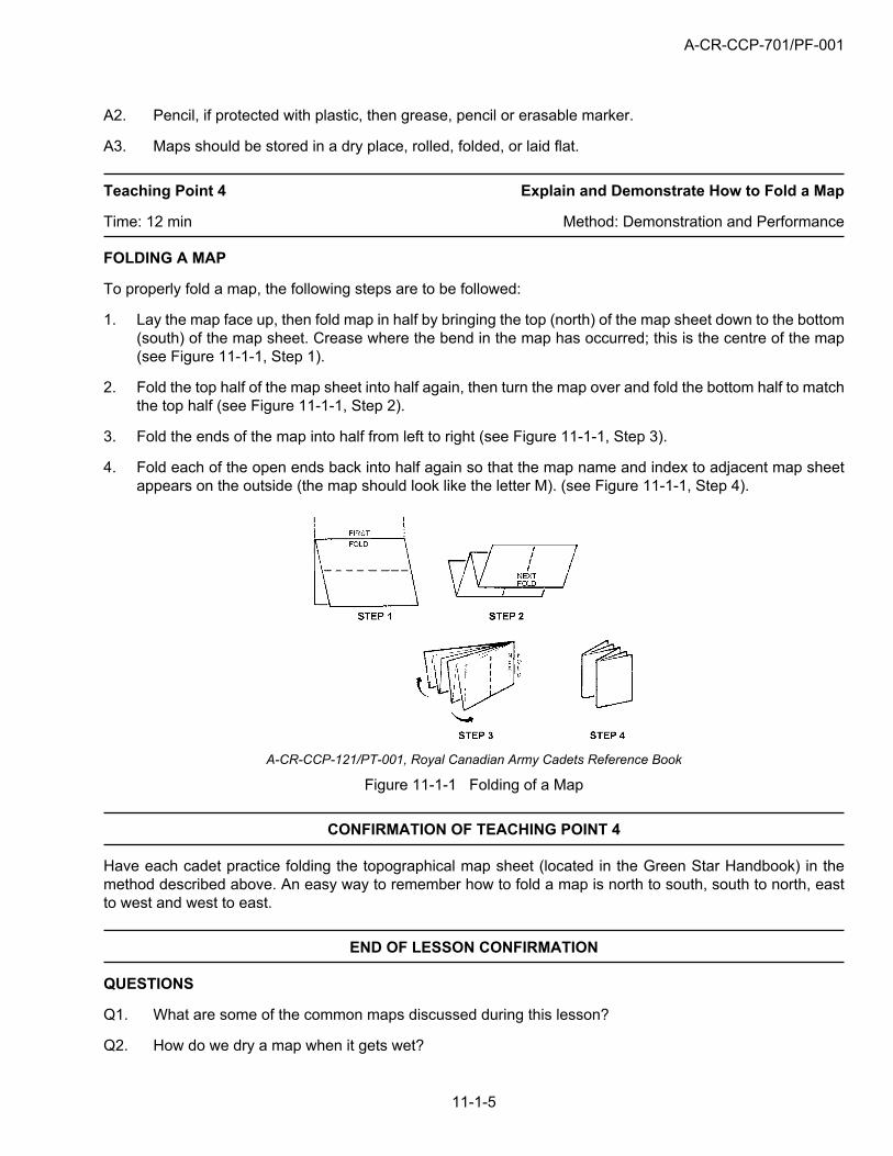
1. Lay the map face up, then fold map in half by bringing the top (north) of the map sheet down to the bottom(south) of the map sheet. Crease where the bend in the map has occurred; this is the centre of the map(see Figure 11-1-1, Step 1).
2. Fold the top half of the map sheet into half again, then turn the map over and fold the bottom half to matchthe top half (see Figure 11-1-1, Step 2).
3. Fold the ends of the map into half from left to right (see Figure 11-1-1, Step 3).
4. Fold each of the open ends back into half again so that the map name and index to adjacent map sheetappears on the outside (the map should look like the letter M). (see Figure 11-1-1, Step 4).
A-CR-CCP-121/PT-001, Royal Canadian Army Cadets Reference Book
Figure 11-1-1 Folding of a Map
CONFIRMATION OF TEACHING POINT 4
Have each cadet practice folding the topographical map sheet (located in the Green Star Handbook) in themethod described above. An easy way to remember how to fold a map is north to south, south to north, eastto west and west to east.
END OF LESSON CONFIRMATION
QUESTIONS
Q1. What are some of the common maps discussed during this lesson?
Q2. How do we dry a map when it gets wet?
A-CR-CCP-701/PF-001
11-1-6
Q3. Using a piece of paper, fold it as you would a map.
ANTICIPATED ANSWERS
A1. Topographical, orienteering, street and road, relief, political, statistical, outline and air photo.
A2. Lay flat on a dry clean surface, and let dry completely.
A3. Demonstrate.
CONCLUSION
HOMEWORK/READING/PRACTICE
The instructor shall have cadets’ practice folding a piece of paper as they would a map.
METHOD OF EVALUATION
N/A.
CLOSING STATEMENT
It is important to know the different map types and their uses, so that cadets can select the correct map for theirneeds. Also, knowing how to fold and maintain maps properly will keep them in good condition for a long time.
INSTRUCTOR NOTES/REMARKS
N/A.
REFERENCES
A2-004 B-GL-382-005/FP-001 Canadian Forces. (1976). Maps, Fields, Sketching, and Compasses(Vol. 8). Ottawa, ON: National Defence.
A-CR-CCP-701/PF-001
11-2-1
ROYAL CANADIAN ARMY CADETS
GREEN STAR
INSTRUCTIONAL GUIDE
SECTION 2
EO M122.02 – IDENTIFY MARGINAL INFORMATION AND CONVENTIONAL SIGNS
Total Time: 60 min
INTRODUCTION
PRE-LESSON INSTRUCTIONS
The instructor shall review the lesson content, and become familiar with the material prior to instruction of thislesson.
A complete list of resources needed for the instruction of this EO is located at Chapter 4 of the QSP. Specificuses for said stores are identified throughout the Instructional Guide, within the teaching point for which theyare required.
PRE-LESSON ASSIGNMENT
N/A.
APPROACH
This lesson will be presented using the interactive lecture method. The interactive lecture method was chosen asit best allows the instructor to make a semi-formal presentation of the material allowing the cadets to participateby asking or responding to questions, commenting on the material, or participating in short activities. Thismethod appeals to auditory learners, with the potential for active participation in activities that appeal to tactile/kinaesthetic learners. During TP2 to TP4, the instructor will have an opportunity to confirm the material througha practical exercise.
REVIEW
The pertinent review for this lesson, from EO M122.01 (Section 1), Identify Types of Maps, will include:
Q1. What type of map is most commonly used by the military?
Q2. What are three things we should protect maps from?
Q3. How are maps to be stored?
ANTICIPATED ANSWERS
A1. Topographical.
A2. Water, dirt, and wind.
A3. Maps should be stored in a dry place, and rolled, folded, or laid flat.
A-CR-CCP-701/PF-001
11-2-2
OBJECTIVES
By the end of this lesson the cadet shall be expected to identify map features to include: marginal information,and conventional signs found on a topographical map.
IMPORTANCE
Cadets shall be able to identify features on the map as they relate to objects on the ground. The cadets willapply this knowledge during training where any type of map is to be used.
Teaching Point 1 Identify Marginal Information Found on a Topographical Map
Time: 20 min Method: Interactive Lecture
MARGINAL INFORMATION
The margins provide information important to the full understanding and use of the map. Before using anyunfamiliar map, it is important to have a good look at the information contained in its margins. The layout andcontents of the marginal information should be in relatively the same area for all topographical maps. Thisinformation includes:
name of map sheet;
number of the map and index of adjoining maps;
date of map data;
map scale;
scale bars or graphic linear scales;
contour interval,
military index number, normally found at the top right corner of the map sheet, which is used for orderingadditional maps;
declination diagram;
Universal Transverse Merecator Grid System (UTM); and
legend of conventional signs.
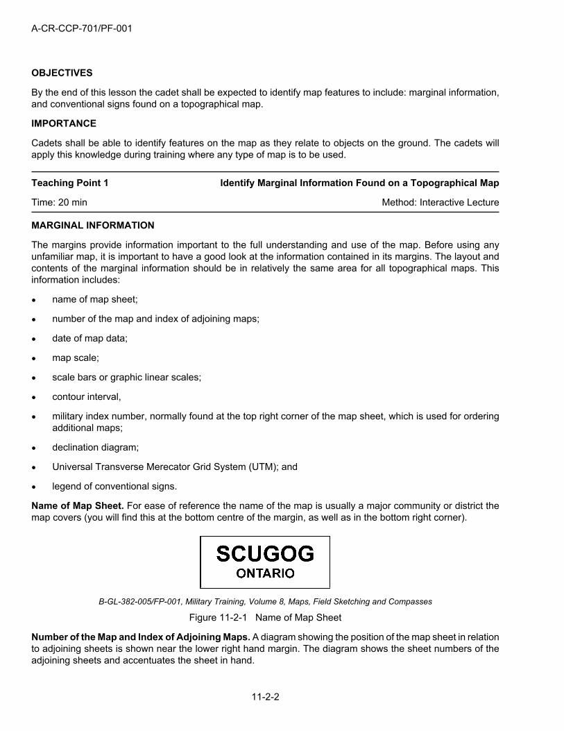
Name of Map Sheet. For ease of reference the name of the map is usually a major community or district themap covers (you will find this at the bottom centre of the margin, as well as in the bottom right corner).
B-GL-382-005/FP-001, Military Training, Volume 8, Maps, Field Sketching and Compasses
Figure 11-2-1 Name of Map Sheet
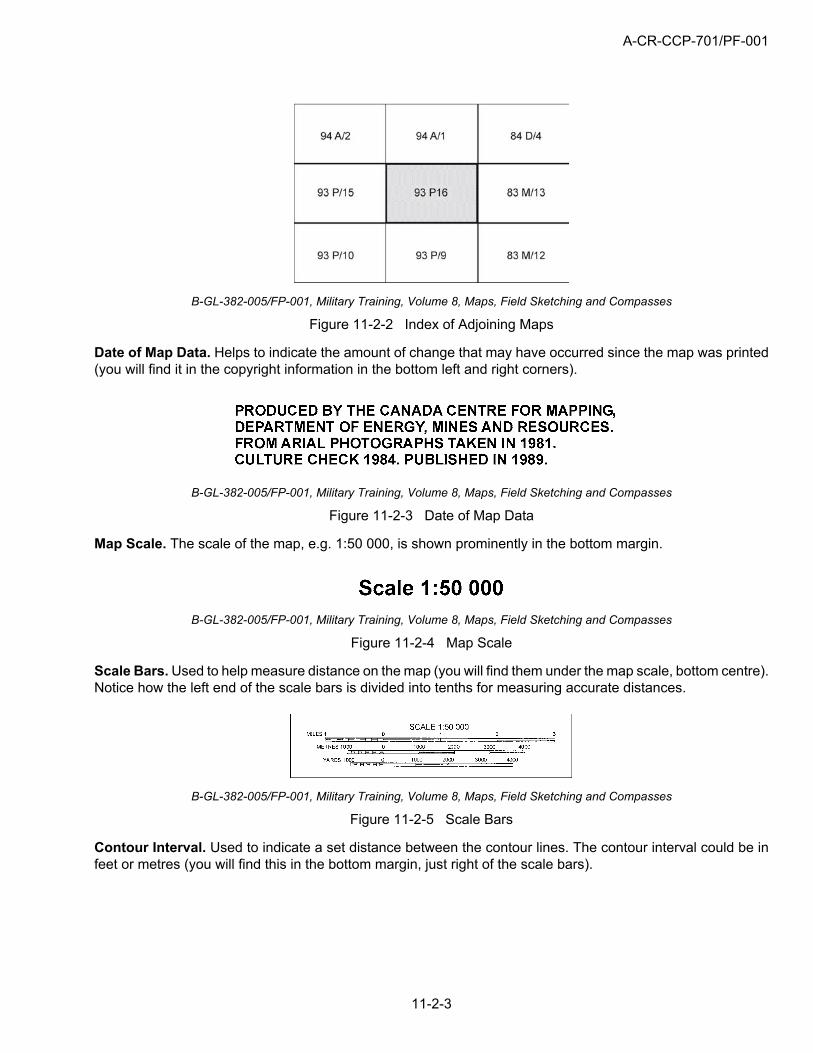
Number of the Map and Index of Adjoining Maps. A diagram showing the position of the map sheet in relationto adjoining sheets is shown near the lower right hand margin. The diagram shows the sheet numbers of theadjoining sheets and accentuates the sheet in hand.
A-CR-CCP-701/PF-001
11-2-3
B-GL-382-005/FP-001, Military Training, Volume 8, Maps, Field Sketching and Compasses
Figure 11-2-2 Index of Adjoining Maps
Date of Map Data. Helps to indicate the amount of change that may have occurred since the map was printed(you will find it in the copyright information in the bottom left and right corners).
B-GL-382-005/FP-001, Military Training, Volume 8, Maps, Field Sketching and Compasses
Figure 11-2-3 Date of Map Data
Map Scale. The scale of the map, e.g. 1:50 000, is shown prominently in the bottom margin.
B-GL-382-005/FP-001, Military Training, Volume 8, Maps, Field Sketching and Compasses
Figure 11-2-4 Map Scale
Scale Bars. Used to help measure distance on the map (you will find them under the map scale, bottom centre).Notice how the left end of the scale bars is divided into tenths for measuring accurate distances.
B-GL-382-005/FP-001, Military Training, Volume 8, Maps, Field Sketching and Compasses
Figure 11-2-5 Scale Bars
Contour Interval. Used to indicate a set distance between the contour lines. The contour interval could be infeet or metres (you will find this in the bottom margin, just right of the scale bars).
A-CR-CCP-701/PF-001
11-2-4
B-GL-382-005/FP-001, Military Training, Volume 8, Maps, Field Sketching and Compasses
Figure 11-2-6 Contour Interval
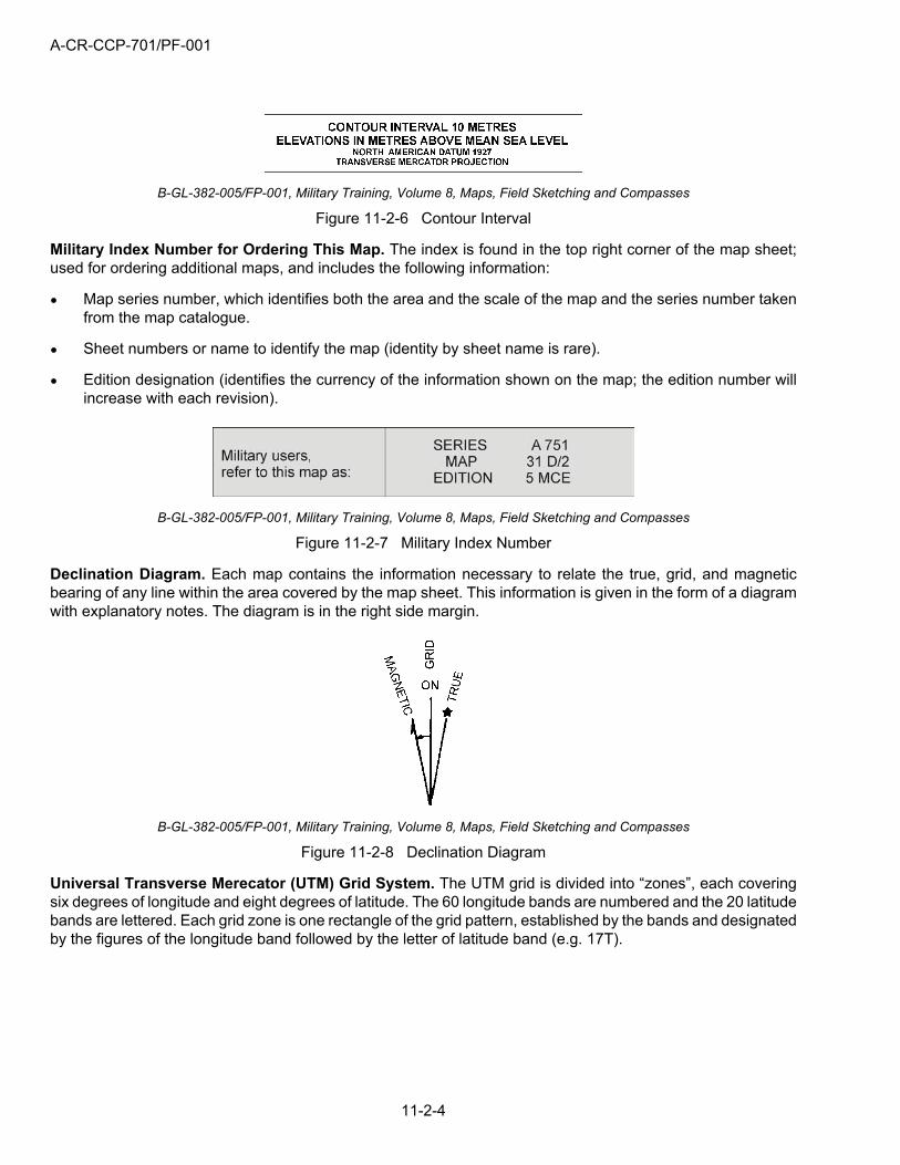
Military Index Number for Ordering This Map. The index is found in the top right corner of the map sheet;used for ordering additional maps, and includes the following information:
Map series number, which identifies both the area and the scale of the map and the series number takenfrom the map catalogue.
Sheet numbers or name to identify the map (identity by sheet name is rare).
Edition designation (identifies the currency of the information shown on the map; the edition number willincrease with each revision).
B-GL-382-005/FP-001, Military Training, Volume 8, Maps, Field Sketching and Compasses
Figure 11-2-7 Military Index Number
Declination Diagram. Each map contains the information necessary to relate the true, grid, and magneticbearing of any line within the area covered by the map sheet. This information is given in the form of a diagramwith explanatory notes. The diagram is in the right side margin.
B-GL-382-005/FP-001, Military Training, Volume 8, Maps, Field Sketching and Compasses
Figure 11-2-8 Declination Diagram
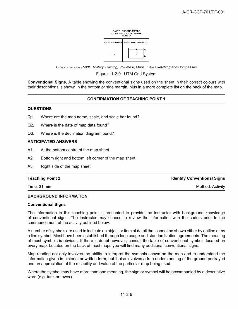
Universal Transverse Merecator (UTM) Grid System. The UTM grid is divided into “zones”, each coveringsix degrees of longitude and eight degrees of latitude. The 60 longitude bands are numbered and the 20 latitudebands are lettered. Each grid zone is one rectangle of the grid pattern, established by the bands and designatedby the figures of the longitude band followed by the letter of latitude band (e.g. 17T).
A-CR-CCP-701/PF-001
11-2-5
B-GL-382-005/FP-001, Military Training, Volume 8, Maps, Field Sketching and Compasses
Figure 11-2-9 UTM Grid System
Conventional Signs. A table showing the conventional signs used on the sheet in their correct colours withtheir descriptions is shown in the bottom or side margin, plus in a more complete list on the back of the map.
CONFIRMATION OF TEACHING POINT 1
QUESTIONS
Q1. Where are the map name, scale, and scale bar found?
Q2. Where is the date of map data found?
Q3. Where is the declination diagram found?
ANTICIPATED ANSWERS
A1. At the bottom centre of the map sheet.
A2. Bottom right and bottom left corner of the map sheet.
A3. Right side of the map sheet.
Teaching Point 2 Identify Conventional Signs
Time: 31 min Method: Activity
BACKGROUND INFORMATION
Conventional Signs
The information in this teaching point is presented to provide the instructor with background knowledgeof conventional signs. The instructor may choose to review the information with the cadets prior to thecommencement of the activity outlined below.
A number of symbols are used to indicate an object or item of detail that cannot be shown either by outline or bya line symbol. Most have been established through long usage and standardization agreements. The meaningof most symbols is obvious. If there is doubt however, consult the table of conventional symbols located onevery map. Located on the back of most maps you will find many additional conventional signs.
Map reading not only involves the ability to interpret the symbols shown on the map and to understand theinformation given in pictorial or written form, but it also involves a true understanding of the ground portrayedand an appreciation of the reliability and value of the particular map being used.
Where the symbol may have more than one meaning, the sign or symbol will be accompanied by a descriptiveword (e.g. tank or tower).
A-CR-CCP-701/PF-001
11-2-6
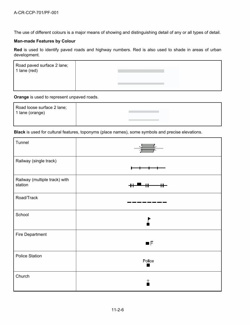
The use of different colours is a major means of showing and distinguishing detail of any or all types of detail.
Man-made Features by Colour
Red is used to identify paved roads and highway numbers. Red is also used to shade in areas of urbandevelopment.
Road paved surface 2 lane;1 lane (red)
Orange is used to represent unpaved roads.
Road loose surface 2 lane;1 lane (orange)
Black is used for cultural features, toponyms (place names), some symbols and precise elevations.
Tunnel
Railway (single track)
Railway (multiple track) withstation
Road/Track
School
Fire Department
Police Station
Church
A-CR-CCP-701/PF-001
11-2-7
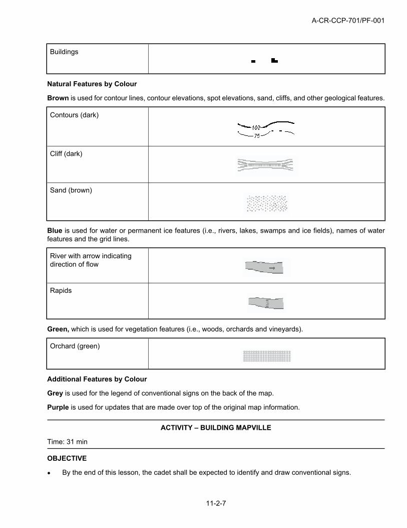
Buildings
Natural Features by Colour
Brown is used for contour lines, contour elevations, spot elevations, sand, cliffs, and other geological features.
Contours (dark)
Cliff (dark)
Sand (brown)
Blue is used for water or permanent ice features (i.e., rivers, lakes, swamps and ice fields), names of waterfeatures and the grid lines.
River with arrow indicatingdirection of flow
Rapids
Green, which is used for vegetation features (i.e., woods, orchards and vineyards).
Orchard (green)
Additional Features by Colour
Grey is used for the legend of conventional signs on the back of the map.
Purple is used for updates that are made over top of the original map information.
ACTIVITY – BUILDING MAPVILLE
Time: 31 min
OBJECTIVE
By the end of this lesson, the cadet shall be expected to identify and draw conventional signs.
A-CR-CCP-701/PF-001
11-2-8
RESOURCES
Flipchart/whiteboard.
Markers/dry erase markers.
ACTIVITY LAYOUT
This activity will be a participative exercise designed to involve the cadets, while teaching the variousconventional signs found on a topographical map. The cadets will design and draw the map for a new towncalled Mapville.
Activity Instructions:
The instructor will draw a large outline of a topographical map on the flipchart/whiteboard at the front ofthe room.
The cadets will be asked to approach the front, one at a time, and draw a conventional sign on thedeveloping map of Mapville.
The cadets must explain what the sign is for and why they chose to put it where they did.
No sign may be used more than once.
The instructor may choose to take a photograph of the finished product, to display around the parade area.
SAFETY
This is a supervised activity.
INSTRUCTOR GUIDELINES
Instructors are to continuously supervise and monitor the activity to ensure the material being presentedis being utilized correctly.
In the event of misplaced or misused conventional signs, the instructor shall stop the cadets, correct theproblem, and have the cadets return to their seats. Have the cadets attempt another sign at the end ofthe activity.
The instructor is to observe carefully, as this activity will constitute the final confirmation of the lesson.
CONFIRMATION OF TEACHING POINT 2
The activity outlined above will serve as the confirmation of this teaching point.
END OF LESSON CONFIRMATION
The activity at the end of TP2 will serve as the confirmation of this lesson.
CONCLUSION
HOMEWORK/READING/PRACTICE
N/A.
A-CR-CCP-701/PF-001
11-2-9
METHOD OF EVALUATION
The cadet will be required to properly identify marginal information and conventional signs found on atopographical map.
CLOSING STATEMENT
The information presented in this lesson will enable the cadet to identify features on the map as they relateto objects on the ground. The cadets will apply this knowledge during any training where any type of map isto be used.
INSTRUCTOR NOTES/REMARKS
Instructors are encouraged to confirm material throughout this lesson with the use of interactive activitiesdesigned to encourage participation while gauging comprehension.
REFERENCES
A2-004 B-GL-382-005-FP-001 Canadian Forces. (1976). Maps, Fields, Sketching, and Compasses(Vol. 8). Ottawa, ON: National Defence.

A-CR-CCP-701/PF-001
THIS PAGE INTENTIONALLY LEFT BLANK
11-2-10
A-CR-CCP-701/PF-001
11-3-1
ROYAL CANADIAN ARMY CADETS
GREEN STAR
INSTRUCTIONAL GUIDE
SECTION 3
EO M122.03 – INTERPRET CONTOUR LINES
Total Time: 30 min
INTRODUCTION
PRE-LESSON INSTRUCTIONS
The instructor shall review the lesson content, and become familiar with the material prior to instruction of thislesson.
PRE-LESSON ASSIGNMENT
N/A.
APPROACH
This lesson will be presented using the demonstration and performance method. The demonstration andperformance method was chosen to allow cadets to participate in supervised exploration of practicalinstructional material. This method provides the instructor the opportunity to introduce the subject matter,demonstrate and explain procedures, and supervise the cadets while they imitate the skill. This method appealsto all learning styles.
REVIEW
The pertinent review for this lesson will include a review of EO M122.02 (Section 2).
Q1. What kind of information is found in the margin of a map?
Q2. What is a conventional sign?
Q3. Which natural features are shown in brown on a map?
ANTICIPATED ANSWERS
A1. Any from the list below:
name of map sheet;
number of the map and index of adjoining maps;
date of map data;
map scale;
scale bars or graphic linear scales;
contour interval;
military index number;
A-CR-CCP-701/PF-001
11-3-2
declination diagram;
Universal Transverse Merecator Grid System (UTM); and
legend of conventional signs.
A2. A symbol used to indicate an object or item of detail that cannot be shown either by outline or by aline symbol.
A3. Brown is used for contour lines, contour elevations, spot elevations, sand, cliffs, and other geologicalfeatures.
OBJECTIVES
By the end of this lesson the cadet shall be expected to interpret contour lines in order to identify the shapeof the ground as depicted on a map.
IMPORTANCE
This information allows the cadet to be able to identify features on the map as they relate to the shape andelevation of the ground. Cadets will apply this knowledge during training where any type of map is to be used.Knowing the shape of the ground will allow cadets to identify major landforms that may be nearby, therebyhelping to identify their position on the map.
Teaching Point 1 Explain and Demonstrate How Contour Lines Indicate theShape of the Ground
Time: 26 min Method: Demonstration and Performance
The teaching of relief on a blackboard or plane surface should be avoided if at all possible.The construction of simple three-dimensional models such as those made out of putty orsoft earth can help, but there is no substitute for outdoor instruction.
DEFINITION OF RELIEF ON A MAP
“Relief,” or elevation, is the shape of the ground in a vertical plane. Relief on a map is the showing of the heightsand shapes of the ground, above mean sea level, in feet or metres.
There are two distinct elements in the representation of relief. These are:
Representation of Height. This is a fact-based representation of the height of the land and of landforms.Differences in appearance on the map will arise from the type, density and accuracy of the informationprovided.
Representation of Shape. This may be largely artistic, and the methods used will vary between maps.
CONTOUR LINES AND INTERVALS
A contour is a line on the map joining points of equal elevation in relationship to sea level, and is the standardmethod of showing relief on topographical maps.
Contours are shown at a regular vertical interval (difference in height between contours lines) that is called thecontour interval. The contour interval is always stated in the margin of the map, normally near the graphic scales.
A-CR-CCP-701/PF-001
11-3-3
Contours are normally drawn as continuous brown lines. Every fourth or fifth contour is called an “Index Contour”and is shown by a thicker brown line; this helps in reading and counting the contours to determine a height.
INTERPRETING CONTOUR LINES
Interpreting contour lines provides a visualization of the shape of the ground, which is shown on the map bycontour lines and contour intervals. Correct interpretation of the shape of the ground from contour lines requirespractice and practical experience on the ground. It is essential to study various features, comparing the mapto the ground in each case.
SLOPES
The instructor shall explain the following landforms by identifying the depiction on the map,followed by showing the landform in the field. In the event that models are being used inplace of real ground, the model shall be introduced as the respective landform is presented.Where putty is used, fishing line can be used to slice through the landform model illustratingthe concept of a contour line.
The distance between contour lines on the map will indicate to you the type of slope on the ground.
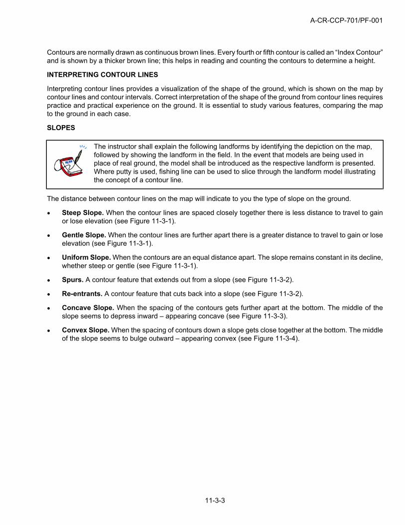
Steep Slope. When the contour lines are spaced closely together there is less distance to travel to gainor lose elevation (see Figure 11-3-1).
Gentle Slope. When the contour lines are further apart there is a greater distance to travel to gain or loseelevation (see Figure 11-3-1).
Uniform Slope. When the contours are an equal distance apart. The slope remains constant in its decline,whether steep or gentle (see Figure 11-3-1).
Spurs. A contour feature that extends out from a slope (see Figure 11-3-2).
Re-entrants. A contour feature that cuts back into a slope (see Figure 11-3-2).
Concave Slope. When the spacing of the contours gets further apart at the bottom. The middle of theslope seems to depress inward – appearing concave (see Figure 11-3-3).
Convex Slope. When the spacing of contours down a slope gets close together at the bottom. The middleof the slope seems to bulge outward – appearing convex (see Figure 11-3-4).
A-CR-CCP-701/PF-001
11-3-4
Basic Map Using A-CR-CCP-108/PT-001
Figure 11-3-1 Gentle/Steep SlopesMap Field Sketch and Compass B-GL-382–005–FP-001
Figure 11-3-2 Spur and Re-entrant
Map Field Sketch and Compass B-GL-382–005–FP-001
Figure 11-3-3 Concave SlopeMap Field Sketch and Compass B-GL-382–005–FP-001
Figure 11-3-4 Convex Slope
CONFIRMATION OF TEACHING POINT 1
QUESTIONS
Q1. The relief on a map shows what two elements?
Q2. What is the name given to the difference in height between contours lines?
Q3. What are some of the different types of slopes identified on a map?
ANTICIPATED ANSWERS
A1. The height and shape of the ground.
A2. The contour interval.
A3. Steep, gentle, uniform, concave and convex.
A-CR-CCP-701/PF-001
11-3-5
END OF LESSON CONFIRMATION
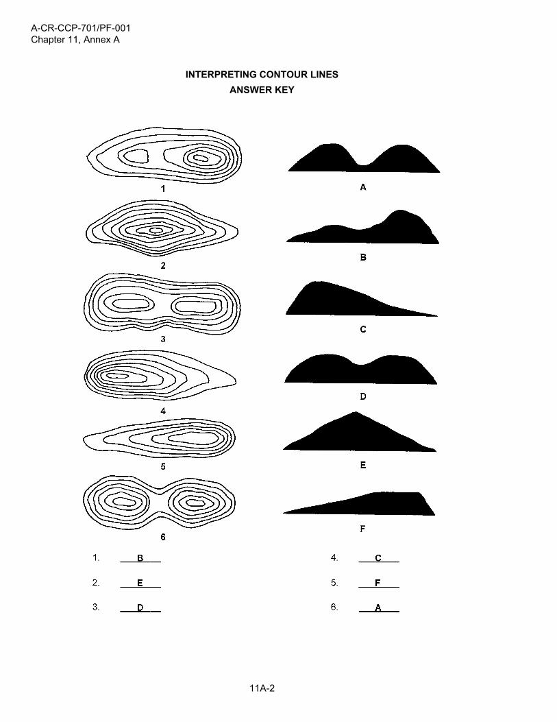
The information learned in this is EO can be practiced with the activity found at Annex A. Allow cadets tocomplete the activity found at Annex A, then have them switch sheets for correcting.
Alternately, the instructor may choose to have the cadets identify the respective features on a map of an areabeing used for an upcoming exercise.
A correctly labelled diagram is located at Page 11-A-2 of Annex A.
CONCLUSION
HOMEWORK/READING/PRACTICE
N/A.
METHOD OF EVALUATION
During the confirmation activity for EO M122.CA, Follow a Route Led by a Section Commander (A-CR-CCP-701/PG-001, Chapter 4, Section 11), the cadets shall be expected to identify their positions by relating majorlandmarks in the immediate vicinity to what is portrayed on the map. Relief types and landforms are excellentpoints of reference for this task.
CLOSING STATEMENT
Knowing how to interpret contour lines allows cadets to visualize the shape of the ground by reading a map.
INSTRUCTOR NOTES/REMARKS
This skill is learned by practice, and is best taught in the outdoors.
REFERENCES
A2-004 B-GL-382-005-FP-001 Canadian Forces. (1976). Maps, Fields, Sketching, and Compasses(Vol. 8). Ottawa, ON: National Defence.

A-CR-CCP-701/PF-001
THIS PAGE INTENTIONALLY LEFT BLANK
11-3-6
A-CR-CCP-701/PF-001
11-4-1
ROYAL CANADIAN ARMY CADETS
GREEN STAR
INSTRUCTIONAL GUIDE
SECTION 4
EO M122.04 – ORIENT A MAP BY INSPECTION
Total Time: 30 min
INTRODUCTION
PRE-LESSON INSTRUCTIONS
The instructor shall review the lesson content and become familiar with the material prior to instruction of thelesson.
A complete list of resources needed for the instruction of this EO is located at Chapter 4 of the QSP. Specificuses for said stores are identified throughout the Instructional Guide, within the teaching point for which theyare required.
PRE-LESSON ASSIGNMENT
N/A.
APPROACH
This lesson will be presented using the interactive lecture method for TP1 and the demonstration andperformance method for TP2. The interactive lecture method was chosen as it best allows the instructor tomake a semi-formal presentation of the material allowing the cadets to participate by asking or respondingto questions, commenting on the material, or participating in short activities. This method appeals to auditorylearners, with the potential for active participation in activities that appeal to tactile/kinaesthetic learners. Thedemonstration-performance method was chosen to allow cadets to participate in supervised exploration ofpractical instructional material. This method provides the instructor the opportunity to introduce the subjectmatter, demonstrate and explain procedures, and supervise the cadets while they imitate the skill. This methodappeals to all learning styles.
REVIEW
The pertinent review for this lesson from EO M122.03 (Section 3) will include:
QUESTIONS
Q1. The relief on a map represents what two elements above mean sea level?
Q2. What is the difference in height between contours lines called?
ANTICIPATED ANSWERS
A1. The height and shape of the ground.
A2. The contour interval.
A-CR-CCP-701/PF-001
11-4-2
OBJECTIVES
By the end of this lesson the cadet shall be expected to properly orient a map by inspection.
IMPORTANCE
Orienting a map by inspection makes it easy to relate information on the map to features on the ground. It isimportant to have the map oriented when moving over a complex route in order to reach your destination.
Teaching Point 1 Explain the Purpose of Orienting a Map by Inspection
Time: 3 min Method: Interactive Lecture
ORIENT A MAP BY INSPECTION
Orienting a map by inspection means to turn the map so that, visually, the map directions and map detailcorrespond with that which is on the ground. This is the simplest and quickest way of orienting a map, providedyou have a general idea of your own position.
Orienting the map does a number of things:
it makes it easy to relate the map to the ground when direction and distance on the map correspondsto the ground;
it helps you find your location or direction if you are in doubt; and
when moving over a complex route, or when traveling over long distances, orienting the map will keepyou on the right track.
CONFIRMATION OF TEACHING POINT 1
QUESTIONS
Q1. What does “orienting a map” by inspection mean?
Q2. What three things does orienting a map do?
ANTICIPATED ANSWERS
A1. To turn the map so that visually the map directions and map detail corresponds with that which is onthe ground.
A2. Three things are:
it makes it easy to relate the map to the ground when direction and distance on the map correspondsto the ground;
it helps you find your location or direction if you are in doubt; and
when moving over a complex route, or when traveling over long distances, orienting the map willkeep you on the right track.
A-CR-CCP-701/PF-001
11-4-3
Teaching Point 2 Explain and Demonstrate How to Orient a Map
Time: 22 min Method: Demonstration and Performance
ORIENT A MAP
In order to orient your map by inspection the following steps should be followed:
1. identify your approximate location on the map;
2. identify two or three prominent objects or landmarks on the ground and find them on the map. Try to uselandmarks in different directions;
3. rotate your map until all identified objects on the map line-up with the direction in which objects are locatedon the ground; and
4. check visually to ensure that all features to your front are in front of your position on the map.
CONFIRMATION OF TEACHING POINT 2
The cadets shall practice orienting their maps by inspection. In the event of inclementweather, a mock field environment can be simulated to practice this skill (e.g. placingpictures depicting prominent objects on the walls corresponding to their location on themap).
END OF LESSON CONFIRMATION
QUESTIONS
Q1. What are the four steps to orienting a map by inspection?
ANTICIPATED ANSWERS
A1. In order to orient your map by inspection, you would:
1. identify your approximate location on the map;
2. identify two or three prominent objects or landmarks on the ground and find them on the map. Tryto use landmarks in different directions;
3. rotate your map until all identified objects on the map line up with the direction in which objectsare located on the ground; and
4. check visually to ensure that all features to your front are in front of your position on the map.
CONCLUSION
HOMEWORK/READING/PRACTICE
N/A.
A-CR-CCP-701/PF-001
11-4-4
METHOD OF EVALUATION
The cadet will be required to orient a map by inspection using a topographical map during a field navigationexercise.
CLOSING STATEMENT
Knowing how to visually set your map so that features on the map match those on the ground is important asit enables you to determine the location of an object, or oneself.
INSTRUCTOR NOTES/REMARKS
N/A.
REFERENCES
A2-004 B-GL-382-005-FP-001 Canadian Forces. (1976). Maps, Fields, Sketching, and Compasses(Vol. 8). Ottawa, ON: National Defence.
A-CR-CCP-701/PF-001
11-5-1
ROYAL CANADIAN ARMY CADETS
GREEN STAR
INSTRUCTIONAL GUIDE
SECTION 5
EO M122.05 – DETERMINE A GRID REFERENCE
Total Time: 60 min
INTRODUCTION
PRE-LESSON INSTRUCTIONS
A complete list of resources needed for the instruction of this EO is located at Chapter 4 of the QSP. Specificuses for said stores are identified throughout the Instructional Guide, within the teaching point for which theyare required.
Prior to instructing this lesson the instructor shall:
review the lesson content, and become familiar with the material; and
pre-select grid references to be used in the practical components of this lesson.
PRE-LESSON ASSIGNMENT
N/A.
APPROACH
This lesson will be presented using the interactive lecture method for TP1 and TP3 and the demonstration andperformance methods for TP2 and TP4 to TP6. The interactive lecture method was chosen as it best allowsthe instructor to make a semi-formal presentation of the material allowing the cadets to participate by asking orresponding to questions, commenting on the material, or participating in short activities. This method appealsto auditory learners, with the potential for active participation in activities that appeal to tactile/kinaestheticlearners. The demonstration and performance method was chosen to allow cadets to participate in supervisedexploration of practical instructional material. This method provides the instructor the opportunity to introducethe subject matter, demonstrate and explain procedures, and supervise the cadets while they imitate the skill.This method appeals to all learning styles.
REVIEW
The pertinent review for this lesson from EO M122.04 (Section 4) will include:
Q1. What are the vertical (X-axis) blue lines on a map called?
Q2. What are the horizontal (Y-axis) blue lines on a map called?
Q3. When the writing on a map is the right way up, where is north normally located?
ANTICIPATED ANSWERS
A1. Eastings.
A2. Northings.
A-CR-CCP-701/PF-001
11-5-2
A3. At the top of the map.
OBJECTIVES
By the end of this lesson the cadet shall be expected to determine four and six figure Grid Reference (GR)(within +/- 1000 and 100 metres accuracy, respectively), for a series of features on a topographical map.
IMPORTANCE
As an army cadet it is important to know how to use the grid system. Since the grid system is the basis of mapreading, the concept of a four-figure and six-figure GR will be a stepping stone to becoming a strong map-reader.A GR details the location of a grid square on a map, and prevents confusion about location. Communicationabout exact locations over the radio is made possible with an understanding of a GR.
Teaching Point 1 Explain the Use of Grid Lines
Time: 5 min Method: Interactive Lecture
USE OF GRID SYSTEM
The grid system is a rectangular network of intersecting vertical and horizontal blue lines superimposed on atopographical map. Maps are normally printed so that north is at the top of the sheet when the writing is theright way up. The lines of the grid system are drawn evenly spaced so that one set of lines run north to south(vertically) and the second set of lines run east to west (horizontally). These lines are assigned a sequentialnumber starting in the bottom left corner. The intersecting grid lines at the lower left corner designate a gridsquare.
EASTINGS
Because the vertical lines are numbered from east to west, they are called eastings. Eastings are a seriesof parallel lines plotted as an overlay to the map sheet, with a two-digit number at the top and bottom end ofeach line in the margins.
NORTHINGS
Because the horizontal lines are numbered from the equator toward the north, they are called northings.Northings are a series of parallel lines plotted as an overlay to the map sheet, with a two-digit number at theleft and right end of each line in the margins.
The most southerly point of Canada is Middle Island in Lake Erie, approximately4 620 000 metres from the equator at latitude 41° 41’ north.
CONFIRMATION OF TEACHING POINT 1
QUESTIONS
Q1. When the writing on a map is the right way up, where is north normally located?
Q2. What are the vertical blue lines on a map called?
Q3. What are the horizontal blue lines on a map called?
A-CR-CCP-701/PF-001
11-5-3
ANTICIPATED ANSWERS
A1. At the top of the map.
A2. Eastings.
A3. Northings.
Teaching Point 2 Explain and Demonstrate a Four-figure GR
Time: 12 min Method: Interactive Lecture
GRID REFERENCE
The military traditionally identify grid lines by stating the two-digit number of each grid line. When a location isidentified using the grid system it is call a “Grid Reference” (GR). When giving a GR to a square, the referenceis always to the southwest (bottom left) corner of the square. GRs are always given with the easting value first,followed by the northing value.
FOUR-FIGURE GR
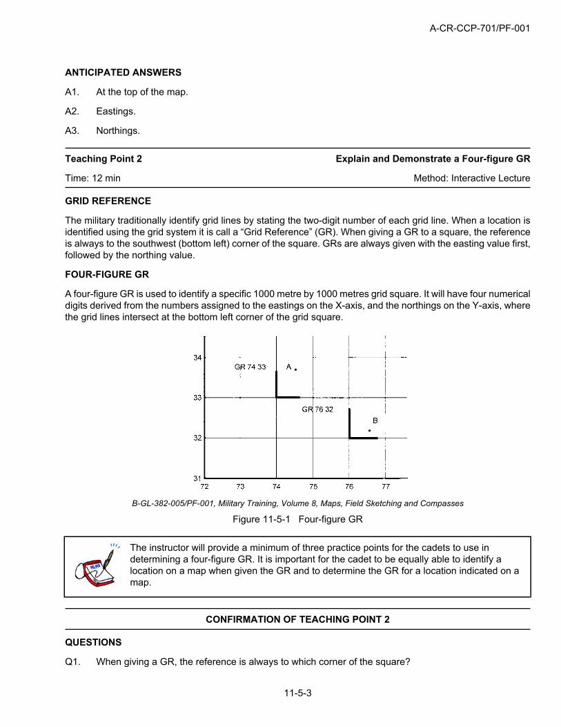
A four-figure GR is used to identify a specific 1000 metre by 1000 metres grid square. It will have four numericaldigits derived from the numbers assigned to the eastings on the X-axis, and the northings on the Y-axis, wherethe grid lines intersect at the bottom left corner of the grid square.
B-GL-382-005/PF-001, Military Training, Volume 8, Maps, Field Sketching and Compasses
Figure 11-5-1 Four-figure GR
The instructor will provide a minimum of three practice points for the cadets to use indetermining a four-figure GR. It is important for the cadet to be equally able to identify alocation on a map when given the GR and to determine the GR for a location indicated on amap.
CONFIRMATION OF TEACHING POINT 2
QUESTIONS
Q1. When giving a GR, the reference is always to which corner of the square?
A-CR-CCP-701/PF-001
11-5-4
Q2. When giving a four-figure GR, in what order are the numbers given?
Q3. A four-figure GR identifies a grid square of what size?
ANTICIPATED ANSWERS
A1. Southwest or bottom left corner.
A2. Eastings then northings, or X-axis then Y-axis.
A3. 1000 metres by 1000 metres.
Teaching Point 3 Explain and Demonstrate How to Determine a Six-figure GR
Time: 12 min Method: Demonstration and Performance
ACCURACY OF A GRID REFERENCE
The accuracy of a four-figure GR on a map sheet with a 1:50 000 scale is 1000 metres. When a more preciselocation is required, a six-figure GR is used which is accurate to 100 metres.
SIX-FIGURE GR
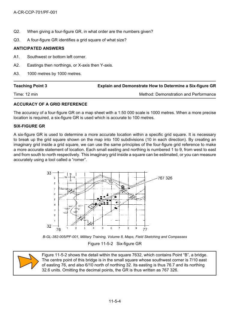
A six-figure GR is used to determine a more accurate location within a specific grid square. It is necessaryto break up the grid square shown on the map into 100 subdivisions (10 in each direction). By creating animaginary grid inside a grid square, we can use the same principles of the four-figure grid reference to makea more accurate statement of location. Each small easting and northing is numbered 1 to 9, from west to eastand from south to north respectively. This imaginary grid inside a square can be estimated, or you can measureaccurately using a tool called a “romer”.
B-GL-382-005/PF-001, Military Training, Volume 8, Maps, Field Sketching and Compasses
Figure 11-5-2 Six-figure GR
Figure 11-5-2 shows the detail within the square 7632, which contains Point “B”, a bridge.The centre point of this bridge is in the small square whose southwest corner is 7/10 eastof easting 76, and also 6/10 north of northing 32. Its easting is thus 76.7 and its northing32.6 units. Omitting the decimal points, the GR is thus written as 767 326.
A-CR-CCP-701/PF-001
11-5-5
Using Figure 11-5-2, the instructor will provide three points for the cadets to use to estimatea six-figure GR and give three six-figure GR cadets can use to locate a point on the map.
CONFIRMATION OF TEACHING POINT 3
QUESTIONS
Q1. Is a six-figure GR more accurate than a four-figure GR?
Q2. To get a six-figure GR, the grid square is divided into how many smaller squares?
Q3. In what order are the numbers given?
ANTICIPATED ANSWERS
A1. Yes.
A2. 100.
A3. Eastings then northings.
Teaching Point 4 Define a Romer and its Use
Time: 8 min Method: Demonstration and Performance
ROMER
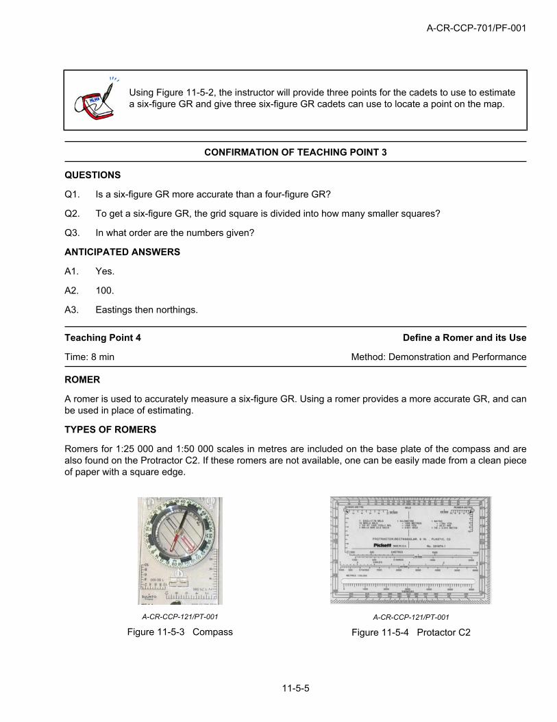
A romer is used to accurately measure a six-figure GR. Using a romer provides a more accurate GR, and canbe used in place of estimating.
TYPES OF ROMERS
Romers for 1:25 000 and 1:50 000 scales in metres are included on the base plate of the compass and arealso found on the Protractor C2. If these romers are not available, one can be easily made from a clean pieceof paper with a square edge.
A-CR-CCP-121/PT-001
Figure 11-5-3 CompassA-CR-CCP-121/PT-001
Figure 11-5-4 Protactor C2
A-CR-CCP-701/PF-001
11-5-6
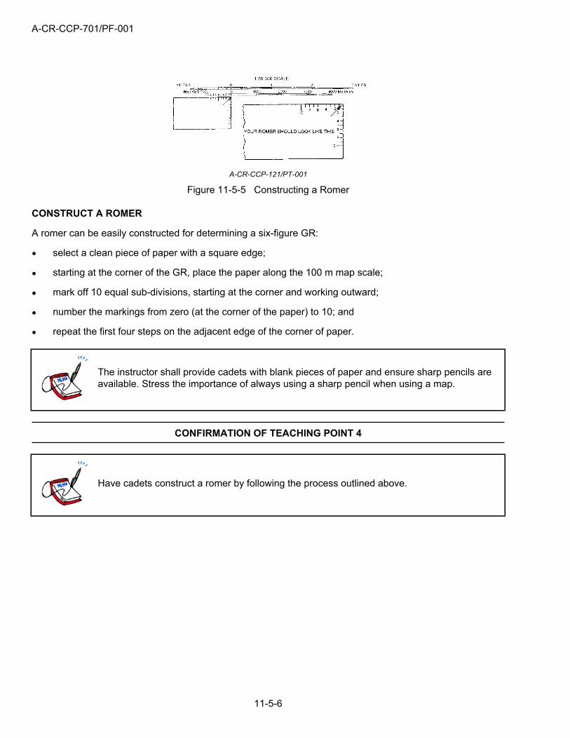
A-CR-CCP-121/PT-001
Figure 11-5-5 Constructing a Romer
CONSTRUCT A ROMER
A romer can be easily constructed for determining a six-figure GR:
select a clean piece of paper with a square edge;
starting at the corner of the GR, place the paper along the 100 m map scale;
mark off 10 equal sub-divisions, starting at the corner and working outward;
number the markings from zero (at the corner of the paper) to 10; and
repeat the first four steps on the adjacent edge of the corner of paper.
The instructor shall provide cadets with blank pieces of paper and ensure sharp pencils areavailable. Stress the importance of always using a sharp pencil when using a map.
CONFIRMATION OF TEACHING POINT 4
Have cadets construct a romer by following the process outlined above.
A-CR-CCP-701/PF-001
11-5-7
Teaching Point 5 Explain and Demonstrate How to Determine a Six-figure GRwith a Constructed Romer
Time: 14 min Method: Demonstration and Performance
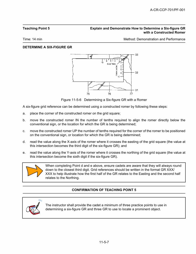
DETERMINE A SIX-FIGURE GR
Figure 11-5-6 Determining a Six-figure GR with a Romer
A six-figure grid reference can be determined using a constructed romer by following these steps:
a. place the corner of the constructed romer on the grid square;
b. move the constructed romer IN the number of tenths required to align the romer directly below theconventional sign, or the location for which the GR is being determined;
c. move the constructed romer UP the number of tenths required for the corner of the romer to be positionedon the conventional sign, or location for which the GR is being determined;
d. read the value along the X-axis of the romer where it crosses the easting of the grid square (the value atthis intersection becomes the third digit of the six-figure GR); and
e. read the value along the Y-axis of the romer where it crosses the northing of the grid square (the value atthis intersection become the sixth digit if the six-figure GR).
When completing Point d and e above, ensure cadets are aware that they will always rounddown to the closest third digit. Grid references should be written in the format GR XXX/XXX to help illustrate how the first half of the GR relates to the Easting and the second halfrelates to the Northing.
CONFIRMATION OF TEACHING POINT 5
The instructor shall provide the cadet a minimum of three practice points to use indetermining a six-figure GR and three GR to use to locate a prominent object.
A-CR-CCP-701/PF-001
11-5-8
END OF LESSON CONFIRMATION
1. The instructor shall provide two points for the cadets to use in determining four-figure GRs.
2. The instructor shall provide two points to use in determining six-figure GRs.
CONCLUSION
HOMEWORK/READING/PRACTICE
N/A.
METHOD OF EVALUATION
The cadet will be required to determine a four-figure GR and a six-figure GR using a constructed romer ona topographical map, as part of the confirmation activity for EO M122.CA, Follow a Route Led by a SectionCommander (A-CR-CCP-701/PG-001, Chapter 4, Section 11).
CLOSING STATEMENT
Knowing how to determine a four-figure and a six-figure GR is essential for functioning safely in the field, fordetermining the accurate location of an object or oneself, and for communicating that position to others.
INSTRUCTOR NOTES/REMARKS
N/A.
REFERENCES
A2-004 B-GL-382-005-FP-001 Canadian Forces. (1976). Maps, Fields, Sketching, and Compasses(Vol. 8). Ottawa, ON: National Defence.
A-CR-CCP-701/PF-001
11-6-1
ROYAL CANADIAN ARMY CADETS
GREEN STAR
INSTRUCTIONAL GUIDE
SECTION 6
EO C122.01 – PRACTICE NAVIGATION AS A MEMBER OF A SMALL GROUP
Total Time: 90 min
INTRODUCTION
PRE-LESSON INSTRUCTIONS
The instructor shall review the lesson content, and become familiar with the material prior to instruction of thislesson.
A complete list of resources needed for the instruction of this EO is located at Chapter 4 of the QSP. Specificuses for said stores are identified throughout the Instructional Guide, within the teaching point for which theyare required.
PRE-LESSON ASSIGNMENT
N/A.
APPROACH
This lesson will be presented using the experiential method. The experiential method was chosen to allowcadets to develop knowledge and skills through a process whereby concepts are derived from, and continuouslymodified by, their own experience. The experiential method combines a short initial activity briefing, a structuredor semi-structured activity, and a reflective group discussion. The instructor supervises the activity and thenleads a group discussion to draw out reflection and connections between the experience and future applicationsof the learning outcomes. This method appeals to tactile/kinaesthetic learners.
REVIEW
The pertinent review for this lesson will include:
a. A review of EO M122.01 (Section 1), Identify Types of Maps.
Q1. What are some common types of maps used?
Q2. What can we use to write on maps?
b. A review of EO M122.02 (Section 2), Identify Marginal Information and Conventional Signs.
Q1. What is the purpose of marginal information?
Q2. What is the purpose of conventional signs?
ANTICIPATED ANSWERS
a. Review of EO M122.01 (Section 1)
A1. Topographical, orienteering, street and road, relief, political, outline, and air photo.
A-CR-CCP-701/PF-001
11-6-2
A2. Pencil (If protected with plastic, grease pencil or erasable marker).
b. Review of EO M122.02 (Section 2)
A1. Marginal information gives information important to the understanding and use of the map.
A2. A symbol used to indicate an object or item of detail that cannot be shown either by outline or bya line symbol.
OBJECTIVES
By the end of this lesson the cadet shall be expected to be better prepared to participate in a short navigationexercise under the supervision of a senior cadet.
IMPORTANCE
The experience of practicing the skills learned in previous lessons will help to enhance the cadets’ navigationskills. Map reading is a skill, which must be learned by practice on the ground. This practice is essential tobuilding up experience, and developing a “feel” for maps, which will allow map reading to become instinctive.
BACKGROUND KNOWLEDGE
ACTIVITY 1 – NAVIGATION USING A STREET MAP
The EO’s covering the information required to conduct this exercise are EO M122.01 (Section 1), Identify Typesof Maps, EO M122.02 (Section 2), Identify Marginal Information and Conventional Signs, and EO M122.05(Section 5), Determine a Grid Reference. Refer to the specified Instructional Guides for further information.
ACTIVITY 2 – NAVIGATION SCAVENGER HUNT
The EO’s covering the information required to conduct this exercise are EO M122.01 (Section 1), Identify Typesof Maps, EO M122.02 (Section 2), Identify Marginal Information and Conventional Signs, and EO M122.04(Section 4), Orient a Map by Inspection. Refer to the specified Instructional Guides for further information.
ACTIVITY 3 – PHOTO NAVIGATION HUNT
The EO’s covering the information required to conduct this exercise are EO M122.01 (Section 1), Identify Typesof Maps, EO M122.02 (Section 2), Identify Marginal information and Conventional Signs, and EO M122.04(Section 4), Orient a Map by Inspection. Refer to the specified Instructional Guides for further information.
ACTIVITY 4 – TRAIL MAP NAVIGATION
The EO’s covering the information required to conduct this exercise are EO M122.01 (Section 1), Identify Typesof Maps, EO M122.03 (Section 3), Interpret Contour Lines, and EO M122.05 (Section 5), Determine a GridReference. Refer to the specified Instructional Guides for further information.
ACTIVITY 1 – NAVIGATION USING A STREET MAP
Time: 90 min
OBJECTIVE
By the end of this activity the cadet shall be expected to be able to navigate using a street map.
RESOURCES
Localized street maps for an optimal group size of four to six cadets.
A-CR-CCP-701/PF-001
11-6-3
Detailed task placard for each checkpoint.
Compass.
ACTIVITY LAYOUT
Using a street map, groups of four to six cadets will navigate within a 2 km radius of the corps location.Predetermined checkpoints set out on prominent objects, located 150 to 250 m apart, will have detailednavigation tasks at each point (e.g. fold a map, identify conventional signs, identify landform, relief typeindicated, ect.), allowing cadets to practice skills taught. This activity shall be conducted in three 30 minuteperiods, allowing for a 15 minute debrief session.
SAFETY
Some rules are to be put in place to ensure the safety of cadets in populated areas with vehicle traffic, as thisexercise will be conducted during evening hours. They shall include; but not be limited to:
have set boundaries determined so cadets do not get lost;
cadets shall obey all local laws and respect personal property;
a staff member shall be present at each checkpoint; and
have a set end time to return for debrief.
INSTRUCTOR GUIDELINES
At this point the instructor shall brief the cadets on any safety rules or any other guidelinespertaining to the activity.
The instructor, with the assistance from senior cadets, shall supervise the cadets.
A staff member shall be present at each checkpoint.
Roaming advisor(s) shall move along the route to allow cadets to seek assistance if required.
ACTIVITY 2 – NAVIGATION SCAVENGER HUNT
Time: 90 min
OBJECTIVE
By the end of this activity the cadet should be more comfortable with navigating with a topographical map.
RESOURCES
Topographical map.
Compass.
ACTIVITY LAYOUT
Using a topographic map, groups of three to four cadets shall navigate to identified points on the map, andhave the task of collecting items/information from these points (e.g. a napkin from a fast food location (withstore’s permission), river rock, phone number from a sign, etc.). Cadets are assigned points based on what
A-CR-CCP-701/PF-001
11-6-4
items/information they are able to obtain. This activity shall be conducted in three 30 minute periods, allowingfor a 15 minute debrief session.
SAFETY
Some rules are to be put in place to ensure the safety of cadets in populated areas with vehicle traffic, as thisexercise will be conducted during evening hours. They shall include but not be limited to:
have set boundaries determined so cadets do not get lost;
cadets shall obey all local laws and respect personal property;
a staff member shall be present at each checkpoint; and
have a set end time to return for debrief.
INSTRUCTOR GUIDELINES
At this point the instructor shall brief the cadets on any safety rules or any other guidelinespertaining to the activity.
The instructor, with the assistance from senior cadets, shall supervise the cadets.
A staff member shall be present at each checkpoint.
Roaming advisor(s) shall move along the route to allow cadets to seek assistance if required.
ACTIVITY 3 – PHOTO NAVIGATION HUNT
Time: 90 min
OBJECTIVE
By the end of this activity the cadet should be more comfortable navigating with a topographical map.
RESOURCES
Topographical map.
Compass.
Romer.
ACTIVITY LAYOUT
Using a topographic map, groups of three to four cadets are given a handout showing a series of photos(e.g. sign, door, bridge, unique tree) taken in the local area. Cadets search out the location of the object in thephoto, and record the six-figure grid reference of that location. Points are assigned based on difficulty of findingthe object. This activity shall be conducted in three 30 minute periods, allowing for a 15 minute debrief session.
SAFETY
Some rules are to be put in place to ensure the safety of cadets in populated areas with vehicle traffic, as thisexercise will be conducted during evening hours. They shall include but not be limited to:
have set boundaries determined so cadets do not get lost;
A-CR-CCP-701/PF-001
11-6-5
cadets shall obey all local laws and respect personal property;
a staff member shall be present at each checkpoint; and
have a set end time to return for debrief.
INSTRUCTOR GUIDELINES
At this point the instructor shall brief the cadets on any safety rules or any other guidelinespertaining to the activity.
The instructor, with the assistance from senior cadets, shall supervise the cadets.
A staff member shall be present at each checkpoint.
Roaming advisor(s) shall move along the route to allow cadets to seek assistance if required.
ACTIVITY 4 – TRAIL MAP NAVIGATION
Time: 90 min
OBJECTIVE
By the end of this activity the cadet shall be expected to understand the layout and use of trail maps.
RESOURCES
Localized map showing an organized trail system.
Compass.
ACTIVITY LAYOUT
Using a trail section of a map, groups of three to six cadets follow a route along an organized trail system. Thisactivity shall be conducted in three 30 minute periods, allowing for a 15 minute debrief session.
SAFETY
Some rules are to be put in place to ensure the safety of cadets if in areas with hiking and cycling traffic, as thisexercise may be conducted during evening hours. They shall include but not be limited to:
have set boundaries determined so cadets do not get lost;
have a set safety bearing;
cadets shall obey all local laws and respect personal property;
a staff member shall be present at each checkpoint; and
have a set end time to return for debrief.
A-CR-CCP-701/PF-001
11-6-6
INSTRUCTOR GUIDELINES
At this point the instructor shall brief the cadets on any safety rules or any other guidelinespertaining to the activity.
The instructor, with the assistance from senior cadets, shall supervise the cadets.
A staff member shall be present at each checkpoint.
Roaming advisor(s) shall move along the route to allow cadets to seek assistance if required.
REFLECTION
Time: 15 min
GROUP DISCUSSION
Instructors shall ensure that all lesson objectives are drawn out towards the end of thereflection stage.
DISCUSSION QUESTIONS
TIPS FOR ANSWERING/FACILITATING DISCUSSION
Ask questions that help facilitate discussion; in other words, avoid questions with yesor no answers.
Prepare questions ahead of time.
Be flexible (you are not bound to only the prepared questions).
Encourage cadets to participate by using praise such as “great idea” or “excellentresponse, can anyone add to that?”
Try to involve everyone by directing questions to non-participants.
SUGGESTED QUESTIONS
Q1. What did this activity teach you about navigation?
Q2. What did you enjoy most about this activity?
Q3. What skills did you feel most comfortable using?
Q4. What skills do you feel you require more practice with?
A-CR-CCP-701/PF-001
11-6-7
Other questions and answers will develop throughout the reflection stage. The discussionshould not be limited to only those suggested. Cadets should be given sufficient time to tellstories of their adventures, and ask questions about any navigation issues that came upduring the activity.
CONCLUSION
REVIEW
Upon completion of the group discussion, the instructor will conclude by summarizing to ensure that all pointshave been covered. The instructor must also take this opportunity to explain how the cadet will apply thisknowledge and/or skill in the future.
MAIN TEACHING POINTS
N/A.
HOMEWORK/READING/PRACTICE
N/A.
METHOD OF EVALUATION
During these activities, the cadet will be required to use skills learned during PO 122 (Identify Location Using aMap), such as types of maps, orient a map by inspection, identify conventional signs, and four and six figure GR.
CLOSING STATEMENT
Map reading is a skill, and true proficiency will only be achieved by practice on the ground. The skills you havelearned during this PO can be used in situations outside of the Cadet Program as well. Practice makes perfect!
INSTRUCTOR NOTES/REMARKS
The checkpoints shall be manned by staff and the cadets are to be asked to record exactly what they see whenthey get there. This will allow the accuracy of the routes to be checked once the activity has been conducted.
REFERENCES
A2-004 B-GL-382-005-FP-001 Canadian Forces. (1976). Maps, Fields, Sketching, and Compasses(Vol. 8). Ottawa, ON: National Defence.

A-CR-CCP-701/PF-001
THIS PAGE INTENTIONALLY LEFT BLANK
11-6-8
A-CR-CCP-701/PF-001Chapter 11, Annex A
11A-1
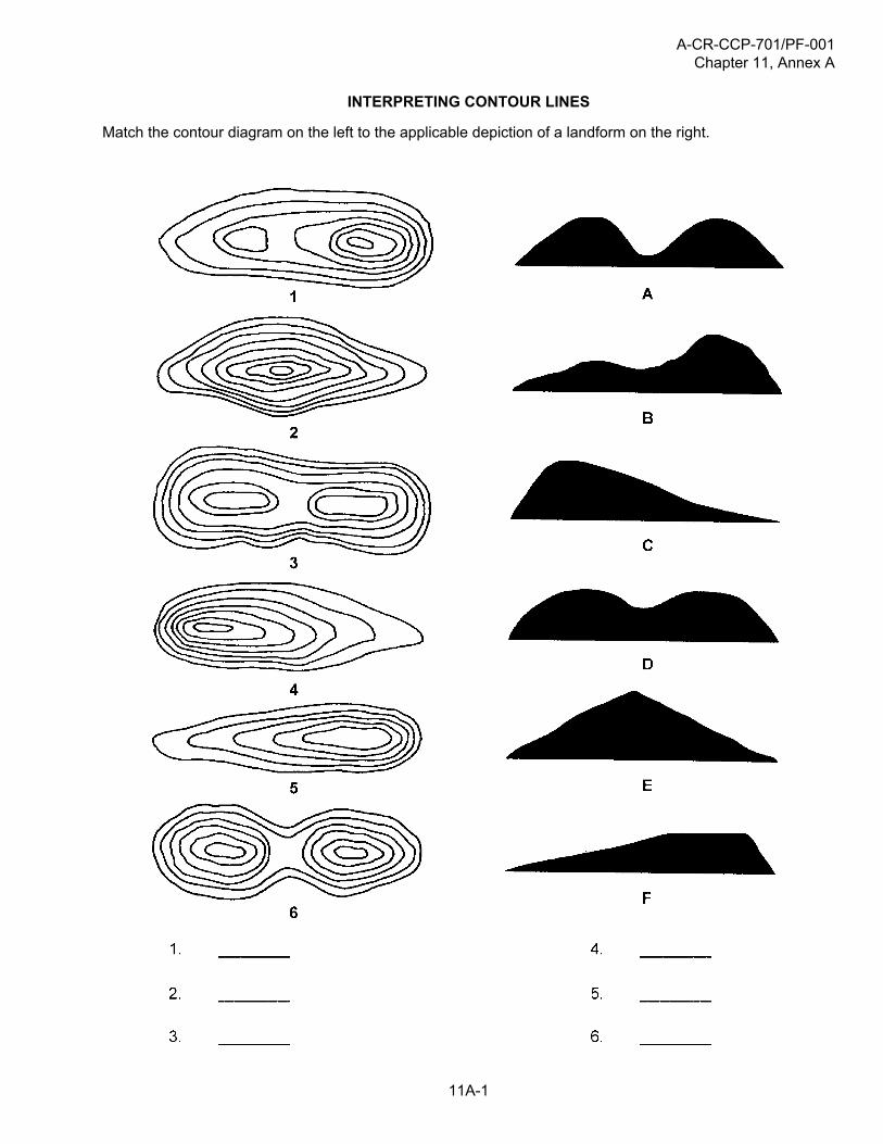
INTERPRETING CONTOUR LINES
Match the contour diagram on the left to the applicable depiction of a landform on the right.
A-CR-CCP-701/PF-001Chapter 11, Annex A
11A-2
INTERPRETING CONTOUR LINESANSWER KEY
Related Documents