LE-SPEED GENERATORS WTW FLUX kk Fardoun, E.F. Fuchs P.W. CarIin Department of Electrical and National Renewable Energy Labomtoy Computer Engineering Golden, C 0 80401 I University of Colorado Boulder, C 0 80309 A cost-competitive, permanent-magnet 20 kW generator is designed such that &e following criteria are satisfied: an (over) load capability of at least 30 kW over the entire speed range of 60-120 rpm, generator weight of about 550 lbs with a maximum radial stator flux density of 0.82 T at low speed, unity power factor operation, acceptably small synchronous reactances and operation without a gear box. To justify his final design four different generator designs are investigated: the first two designs are studied to obh a speed range from 20 to 200 rprn employing rotor field weakening, and the latter two are investigated to ebb a maximum speed range of 40 to 160 rprn based on field weakening via the stator excitation. The generator reactances and induced voltages are computed using finite elementldifference solutions. Generator losses and efficiencies are presented for all four designs at rated temperature of TF1200C. INTRODUCTION Most generator choices for wind turbines sized in the 50-3000 kW range are of the synckp-onous,squhel- cage induction and wound-rotor induction machine type. These generators have limitations on speed range: (constant, or + 20%), and some have a relatively low power factor (e.g., p.f. c 0.9) on the m a c h e md power system sides of the plant [1,2]. Others attempt to increase the speed range by operating a wound-rotor hd~cblogu machine as a doubly fed generator [3]; the cost and complexity of this type make it undesirable. Also, cment harmonics on the power system side are not controlled which degrade the quality of power, rherefore, irequmg passive filters and power factor correction capacitors. Moreover, all wind generators that have been built rely heavily on gear boxes. Since the gear box of a wind power plant needs to be maintained at appreciable cost about every five years [4], and is an expensive part of a wind power system, it would be advantageous to build a plant without one. In Figure 1, a novel variable-speed wind power train is imoduced. It will have the foliiowhg characteristics: A permanent-magnet machine (PMM) with a speed range of 60-120 rpm with minimum weight, size md wmber of poles. A newly developed buck-type rectifier [5] --which maintains a high power factor as well, as a low totd nic current distortion-- utilizing only one active switch will be used to rectify the generator output volibge. voltage will then be converted to ac via an inverter. The output inverter current is controlled to produce a desired power factor as well as any desired harmonic content and thus acts as an active filter. inverter current will be controlled such that noninteger harmonics do not exist and selected eliminated to prevent resonance phenomena. Since PMMs have inherent advantages over induction and synchronous machines --such as Kgher efficiency, no brushes, no excitation losses and no field coils or virtually no rotor losses [6]-- a pemmewt-magnet generator is chosen for this wind power plant application. Four different permanent-magnet m a c h e desig~ns generating a minimum no-load voltage of ~ ~ - ~ = d 3 . 1 8 5 V= 320.4 V, are explored. The speed rmge for these machines varies from 60-120 rprn (design #3) to 20-200 rprn (design #2). The main objective of this paper is to investigate and design a Ph4M for wind power applications. The PMM should generate 1.5 times the rated ouput power over the desired speed range. To produce the maximum real output power the machine is opemted at unity power factor. To approximately optimize the Ph4M design, the "chosen" configuration is compaed with thee other designs having different speed ranges and control schemes. A comparison of the four designs baed upon magnet costs (volume), efficiency, weight and machine size is performed. DESIGN OF 20 kW GENERATOR WITH FLUX WEAKENING Two alternative three-phase permanent-magnet machine types for the generator design are considered. h the first one the flux weakening is achieved via an additional rotor coil counteracting the penramewt-magnet excitation as speed increases. For this type two alternative designs (design # 1 and design # 2) are compaed. The reason for studying two different designs is to investigate the possibility of a machine with a 1:10 speed mge.

Welcome message from author
This document is posted to help you gain knowledge. Please leave a comment to let me know what you think about it! Share it to your friends and learn new things together.
Transcript
LE-SPEED GENERATORS WTW FLUX
kk Fardoun, E.F. Fuchs P.W. CarIin Department of Electrical and National Renewable Energy Labomtoy Computer Engineering Golden, C 0 80401 I
University of Colorado Boulder, C 0 80309
A cost-competitive, permanent-magnet 20 kW generator is designed such that &e following criteria are satisfied: an (over) load capability of at least 30 kW over the entire speed range of 60-120 rpm, generator weight of about 550 lbs with a maximum radial stator flux density of 0.82 T at low speed, unity power factor operation, acceptably small synchronous reactances and operation without a gear box. To justify h i s final design four different generator designs are investigated: the first two designs are studied to o b h a speed range from 20 to 200 rprn employing rotor field weakening, and the latter two are investigated to ebb a maximum speed range of 40 to 160 rprn based on field weakening via the stator excitation. The generator reactances and induced voltages are computed using finite elementldifference solutions. Generator losses and efficiencies are presented for all four designs at rated temperature of TF1200C.
INTRODUCTION Most generator choices for wind turbines sized in the 50-3000 kW range are of the synckp-onous, squhel-
cage induction and wound-rotor induction machine type. These generators have limitations on speed range: (constant, or + 20%), and some have a relatively low power factor (e.g., p.f. c 0.9) on the m a c h e md power system sides of the plant [1,2]. Others attempt to increase the speed range by operating a wound-rotor hd~cblogu machine as a doubly fed generator [3]; the cost and complexity of this type make it undesirable. Also, cment harmonics on the power system side are not controlled which degrade the quality of power, rherefore, irequmg passive filters and power factor correction capacitors. Moreover, all wind generators that have been built rely heavily on gear boxes. Since the gear box of a wind power plant needs to be maintained at appreciable cost about every five years [4], and is an expensive part of a wind power system, it would be advantageous to build a plant without one.
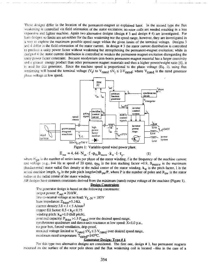
In Figure 1, a novel variable-speed wind power train is imoduced. It will have the foliiowhg characteristics: A permanent-magnet machine (PMM) with a speed range of 60-120 rpm with minimum weight, size m d wmber of poles. A newly developed buck-type rectifier [5] --which maintains a high power factor as well, as a low totd
nic current distortion-- utilizing only one active switch will be used to rectify the generator output volibge. voltage will then be converted to ac via an inverter. The output inverter current is controlled to produce a
desired power factor as well as any desired harmonic content and thus acts as an active filter. inverter current will be controlled such that noninteger harmonics do not exist and selected eliminated to prevent resonance phenomena.
Since PMMs have inherent advantages over induction and synchronous machines --such as Kgher efficiency, no brushes, no excitation losses and no field coils or virtually no rotor losses [6]-- a pemmewt-magnet generator is chosen for this wind power plant application. Four different permanent-magnet m a c h e desig~ns generating a minimum no-load voltage of ~ ~ - ~ = d 3 . 1 8 5 V= 320.4 V, are explored. The speed rmge for these machines varies from 60-120 rprn (design #3) to 20-200 rprn (design #2). The main objective of this paper is to investigate and design a Ph4M for wind power applications. The PMM should generate 1.5 times the rated ouput power over the desired speed range. To produce the maximum real output power the machine is opemted at unity power factor. To approximately optimize the Ph4M design, the "chosen" configuration is compaed with thee other designs having different speed ranges and control schemes. A comparison of the four designs baed upon magnet costs (volume), efficiency, weight and machine size is performed.
DESIGN OF 20 kW GENERATOR WITH FLUX WEAKENING Two alternative three-phase permanent-magnet machine types for the generator design are considered. h
the first one the flux weakening is achieved via an additional rotor coil counteracting the penramewt-magnet excitation as speed increases. For this type two alternative designs (design # 1 and design # 2) are compaed. The reason for studying two different designs is to investigate the possibility of a machine with a 1:10 speed m g e .
These designs differ in the location of the permanent-magnet as explained later. In the second type the flux we&e~ng is controlled via field orientation of the stator excitation; no rotor coils are needed resulting in a less expensive and lighter machine. Again two alternative designs (design # 3 and design # 4) are investigated. For both designs no limits are set neither for the flux weakening nor the speed range, however, they are investigated in a way to explore the maximum possible speed range within the given limits-of the terminal-voltage. ~ e s i ~ n s 3 and 4 differ in the field orientation of the stator current. In design # 3 the stator current distribution is controlled 80 produce a unity power factor without weakening but strengthening the permanent-magnet excitation; while in design .ji 4 the stator current distribution is controlled to weaken the permanent-magnet excitation disregarding the unity power factor constraint. Because neodymium-iron-boron permanent-magnet material has a larger coercivity and a greater energy product than other permanent-magnet materials and thus a higher powerlweight ratio [6] , it is used for this generator. Since the machine speed is proportional to the phase voltage (Eq. 1). using flux we,a&;ehg will bound the terminal voltage (Vt) to Vrated 5Vt 5 2'Vrated; where Vrated is the rated generator phase voltage at low speed.
m
synchrooous circuit
generator
control signals
-L=240V
power system
Figure 1: Variable-speed wind power plant.
Em =4.44 .Np, . f -9 ,B ,,,, -k, . 1 - ~ , , (1) where Nph is the number of series turns per phase of the stator winding, f is the frequency of the machine current ;m,ad voltage (e.g., f=4 Hz at speed of 20 rpm), M;, is the iron stacking factor =0.9, BmmW is the maximum (fmdmenail) stator radial flux density at the radial center of the stator winding, kw is the pitch factor, 1 is the actual m a c ~ e length, -cp is the pole pitch length=2nRsw/P, where P is the number of poles and Rsw is the stator radius at the radial center of the stator winding. MI designs have common constraints derived from the minimum (rated) output voltage of the machine (Figure 1).
The generator design is based on the following constraints: ouQur power: Pout = 20 kW, Ihnse-to-neutral voltage at no load: VL-N = 185V base impedance: zbse=5. 14Q, caaarent densify3.8 < J < 5 Nmm2 copper fill factor: 0.5 < ks< 0.75 w h b g pitch: kw=l.O (full pitch), overload capacity: Pm, > 1.5 Prated over the desired speed range, spclaronous quadrature and direct-axis reactance at low speed: X<1.0 p.u., no gear box, forced ventilation, drip-proof, t e m h d voltage limited to Vrated 5Vt 5 2.Vrated over desired speed range, m a h u m rated temperature: Trated= 140°C.
FOP this type two alternative designs are considered. The first one, design # 1, has permanent magnets momted on the surface of the rotor pole shoes and the flux weakening coil is located --like in the case of a
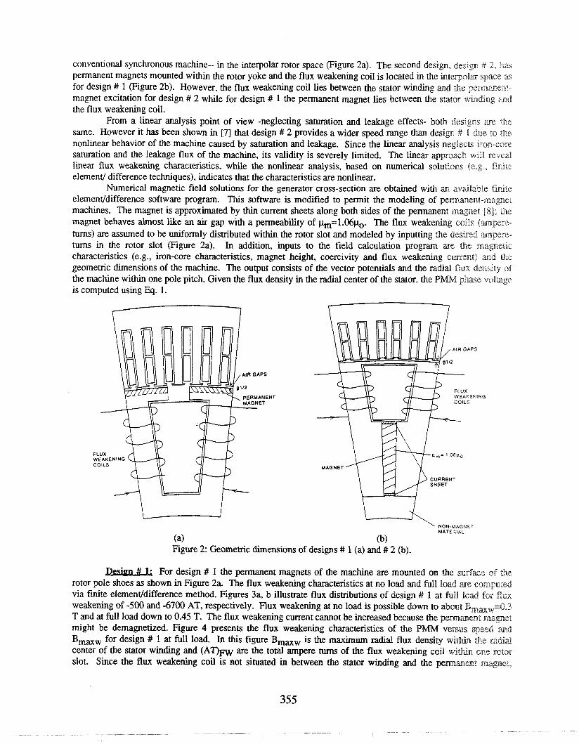
conventional synchronous machine-- in the interpolar rotor space (Figure 2a). The second design, des~gn 4 2. has permanent magnets mounted within the rotor yoke and the flux weakening coil is located in the i n t e ~ o l s space a for design # 1 (Figure 2b). However, the flux weakening coil lies between the stator winding and the pemment- magnet excitation for design # 2 while for design # 1 the permanent magnet lies between the stator w h d k g 'and the flux weakening coil.
From a linear analysis point of view -neglecting saturation and leakage effects- both designs are the same. However it has been shown in [7] that design # 2 provides a wider speed range than design # 1 due to the nonlinear behavior of the machine caused by saturation and leakage. Since the linear analysis neglects iron-core saturation and the leakage flux of the machine, its validity is severely limited. The linear approach will reved linear flux weakening characteristics, while the nonlinear analysis, based on numerical solutnons (e.g . finlre element/ difference techniques), indicates that the characteristics are nonlinear.
Numerical magnetic field solutions for the generator cross-section are obtained with an avdlable fimte elemenvdifference software program. This software is modified to permit the modeling of pernameeat-magnet machines. The magnet is approximated by thin current sheets along both sides of the permanent magnet 183; the magnet behaves almost like an air gap with a permeability of p,,,=1.06po. The flux weakening coils Qmpere- turns) are assumed to be uniformly distributed within the rotor slot and modeled by inputting the desired m p e s e - turns in the rotor slot (Figure 2a). In addition, inputs to the field calculation program are the magnetic characteristics (e.g., iron-core characteristics, magnet height, coercivity and flux weakening current) m d the geometric dimensions of the machine. The output consists of the vector potentials and the radial flux density of the machine within one pole pitch. Given the flux density in the radial center of the stator, the P M phase voiiuge is computed using Eq. 1.
NON-MAGNET MATERIAL
(a) (b) Figure 2: Geometric dimensions of designs # 1 (a) and # 2 (b).
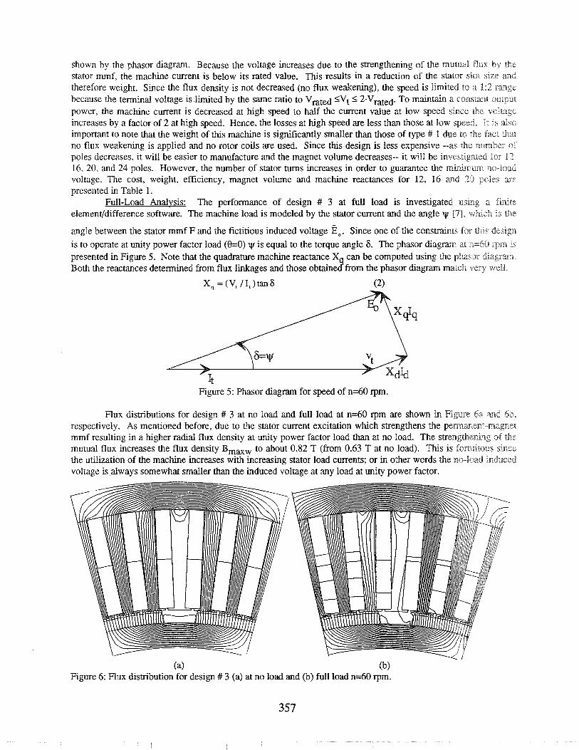
For design # 1 the permanent magnets of the machine are mounted on the w f z e sf the rotor pole shoes as shown in Figure 2a. The flux weakening characteristics at no load and full load are computed via frnite element/difference method. Figures 3a, b illustrate flux distributions of design # 1 at full load for flux weakening of -500 and -6700 AT, respectively. Flux weakening at no load is possible down to about Bmm,=0.3 T and at full load down to 0.45 T. The flux weakening current cannot be increased because the pemmuaena mznignet might be demagnetized. Figure 4 presents the flux weakening characteristics of the PMM versus sped m d BmmW for design # 1 at full load. In this figure BmaW is the maximum radial flux density w i w the radial center of the stator winding and (AT)Fw are the total ampere turns of the flux weakening coil w i w one meor slot. Since the flux weakening coil is not situated in between the stator winding and the pemment magnet,
m a t u r e reaceion and leakage flux effects limit the flux density reduction to 0.45 T and one achieves a speed rwge of 1:4.
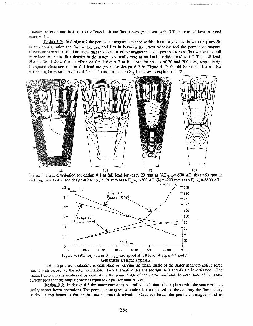
In design # 2 the permanent magnet is placed within the rotor yoke as shown in Figures 2b. h this co~gwat ion the flux weakening coil lies in between the stator winding and the permanent magnet. Nonahex nm~eriical solutions show that this location of the magnet makes it possible for the flux weakening coil HO reduce the radial flux density in the stator to virtually zero at no load condition and to 0.2 T at full load. Figmes 3c, d show flux distributions for design # 2 at full load for speeds of 20 and 200 rpm, respectively. Computed ch~acteristics at full load are given for design # 2 in Figure 4. It should be noted that as flux we&eter.ging increases the value of the quadrature reactance (X,) increases as explainxi !I '
(a) (b) (c) ( 4 Figme 3: Field distribution for design # 1 at full load for (a) n=20 rprn at ( A T ) w - 5 0 0 AT, (b) n=80 rpm at jAT)m=-67i704) AT, and design # 2 for (c) n=20 rpm at (AT)FW=-500 AT, (b) n=200 rpm at (AT)rn=-6600 AT .
200
180
160
140
120
100
80
60
40
20
0 1000 2000 3000 4000 5000 6000 7000
Figure 4: ( A T ) w versus Bmw and speed at full load (designs # 1 and 2).
lhna this type flux weakening is c angle of the stator magnetomotive force (mf) with respect to the rotor excitation. Two alternative designs (designs # 3 and 4) are investigated. The magnet exciation is weakened by controlling the phase angle of the stator mmf and the amplitude of the stator cment mch that the output power is equal to or greater than 20 kW.
In design # 3 the stator current is controlled such that it is in phase with the stator voltage ( ~ t y power factor operation). The permanent-magnet excitation is not opposed, on the contrary the flux density in the air gap increases due to the stator current distribution which reinforces the permanent-magnet mmf as
shown by the phasor diagram. Because the voltage increases due to the strengthening of the ~ n u t u d flux by the stator mmf, the machine current is below its rated value. This results in a reduction of the stator slot srze and therefore weight. Since the flux density is not decreased (no flux weakening), the speed is limited to a B:2 range because the terminal voltage is limited by the same ratio to Vwted <Vt 5 2'Vrated. To maintain a ConsLant output power, the machine current is decreased at high speed to half the current value at low speed since the volmge increases by a factor of 2 at high speed. Hence, the losses at high speed are less than those at low speed. It 1s dss impofimt to note that the weight of this machine is significantly smaller than those of type # 1 due to fie fact that no flux weakening is applied and no rotor coils are used. Since this design is less expensive --as the number of poles decreases, it will be easier to manufacture and the magnet volume decreases-- it will be investigated for 13. 16, 20. and 24 poles. However, the number of stator turns increases in order to guarantee the manhum no-load voltage. The cost, weight, efficiency, magnet volume and machine reactances for 12, 16 and 20 p i e s are presented in Table 1.
Full-Load Analvsis: The performance of design # 3 at full load is investigated using a f i t e element/difference software. The machine load is modeled by the stator current and the angle [7], which is ~ h e
angle between the stator nunf F and the fictitious induced voltage E,. Since one of the consrrainrs for this design is to operate at unity power factor load (8=0) y is equal to the torque angle 6 . The phasor diagrm at n=60 Trn is presented in Figure 5. Note that the quadrature machine reactance X can be computed using the phasor diagram. Both the reactances determined from flux linkages and those obtainec?from the phasor diagram match very well.
Figure 5: Phasor diagram for speed of n=60 rpm.
Flux distributions for design # 3 at no load and full load at n=60 rpm are shown in Figure 6a and 6b, respectively. As mentioned before, due to the stator current excitation which strengthens the pemmene-magnet mmf resulting in a higher radial flux density at unity power factor load than at no load. The s m e n g h e ~ g of the mutual flux increases the flux density BmGw to about 0.82 T (from 0.63 T at no load). This is fomisous sknce the utilization of the machine increases with increasing stator load currents; or in other words the no-load induced voltage is always somewhat smaller than the induced voltage at any load at unity power factor.
( 4 (b) Figure 6: Flux distribution for design # 3 (a) at no load and (b) full load n=60 rpm.
Calculation of Direct and Quadrature Svnchronous Inductances: The direct (Ld) and quadrature (Lq) nnducezulces of one phase of the stator winding of the machine are defined as
Ld'Lmd+Ldl+Lde and Lq=Lmq+Lql+Lqe, (3a, b) where Ldl and Lde are the mutual, le'akage and end leakage direct inductances, respectively; Lmq, Lql and Lqe ;ire the mutual, leakage and end leakage quadrature inductances. Note that all inductance values for the direct and qua&amre inductances are computed using the same flux linkage method explained below, except that v=90° for Ld while y=OO for Lq.
S-inchronous Self Inductunce without LC: The synchronous inductance is computed using the flux- limkiage anerhod [9]
L = Y / I , (4)
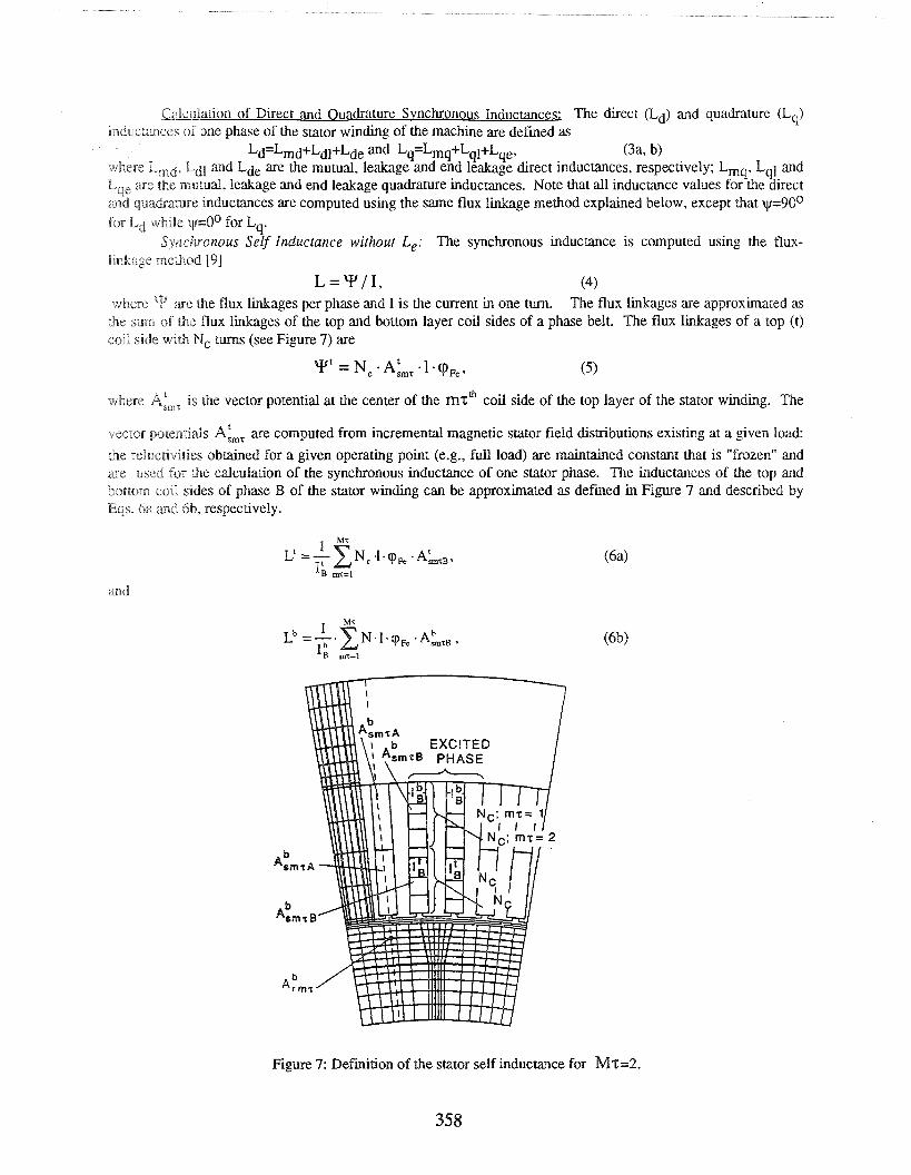
where are the flux linkages per phase and I is the current in one turn. The flux linkages are approximated as the sum of the flux linkages of the top and bottom layer coil sides of a phase belt. The flux linkages of a top (t) coil side with Nc turns (see Figure 7) are
where A:,,, is the vector potential at the center of the r n ~ ' coil side of the top layer of the stator winding. The
vector potendals A:,, are computed from incremental magnetic stator field distributions existing at a given load:
the reYuctivities obtained for a given operating point (e.g., full load) are maintained constant that is "frozen" and are used for the calculation of the synchronous inductance of one stator phase. The inductances of the top and bottom coil sides of phase B of the stator winding can be approximated as defined in Figure 7 and described by Eqs. 6a and bib, respectively.
Figure 7: Definition of the stator self inductance for M7=2.
358
where M7 is the number of coils per pole, A&,, is the vector potential at the center of the rn?' boetom~ layer
coil side of the &%tor winding of phase B and 1; is the current in one turn of the coil side. The surn of Eqs. ($;a)
;md (6b) is the inductance of a phasebelt L~ for i=A, B and C. The direct (Xd) or quadrature (Xq) reacuece of phase can now be computed as
xs =2nf - P ( L ~ + L ~ + ~ ~ ) / a . m , , (7) where p is the number of phasebelts in series which is equal to the number of poles P for the connection at hand. a is the number of phasebelts in parallel which is 1 for the given application, and ms is the number of sracor phases. The direct and quadrature synchronous reactance values per phase of the machine are listed in Table I .
Armuture Leakage Reac.tunces: The leakage flux linkages are computed using Eq. 4. Since she flux linkages for the leakage inductance are those that link the stator and do not link the rotor (see Figure 7). Equation 5 is modified as
b where y, are the total flux linkages (top and bottom coils) for the leakage inductance, A:,, and A,,, aJe the
vector potentials within the top and bottom layers of the mzth coil in the stator and A, is the comesponding
rotor vector potential as shown in Figure 7. Again y=90° for Ldl while v=OO for Lql. Assuming that the top and. bottom layers of the stator coil (phase B) have the same current the leakage inductance corresponding to phase B is
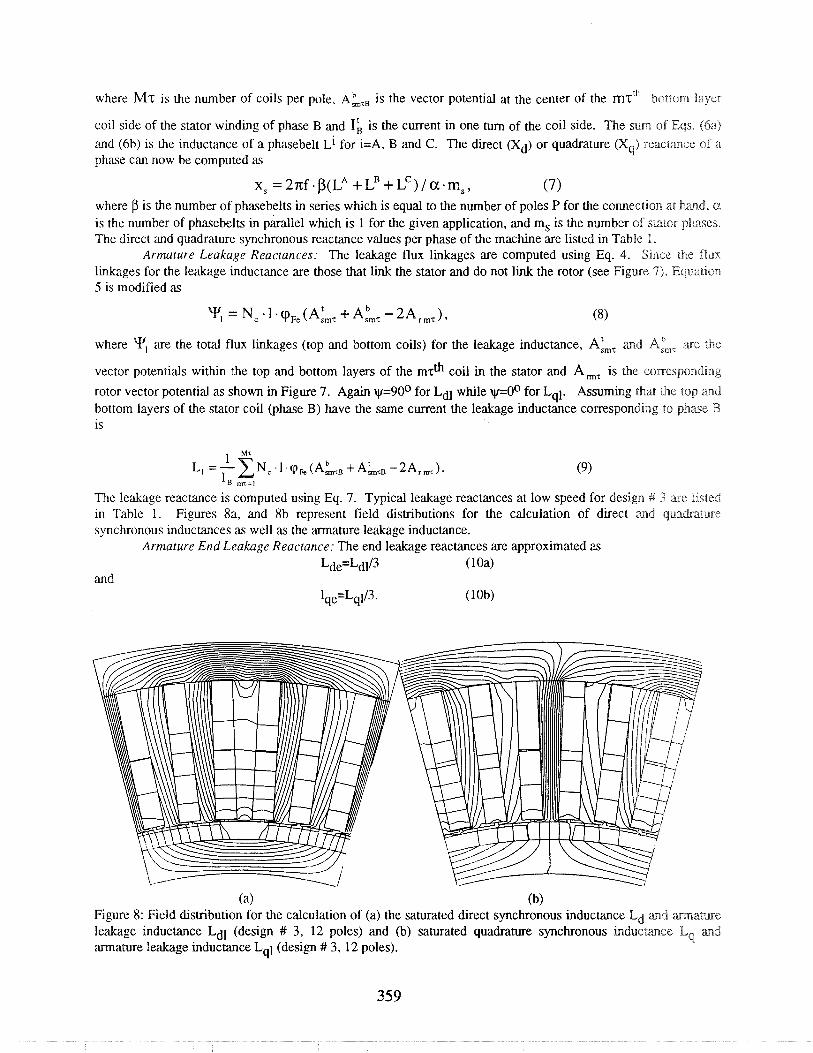
The leakage reactance is computed using Eq. 7. Typical leakage reactances at low speed for design # 3 are listed in Table 1. Figures 8a, and 8b represent field distributions for the calculation of direct ,and quadsatuse synchronous inductances as well as the armature leakage inductance.
Armature End Leakage Reuctance: The end leakage reactances are approximated as Lde'Ldl/3 ( 10a)
and Iqe=Lq1/3. (1 0b)
(a) (b) Figure 8: Field distribution for the calculation of (a) the saturated direct synchronous inductance Ld and m a m e leakage inductance L ~ J (design # 3, 12 poles) and (b) saturated quadrature synchronous inducmce Eq marad annature leakage inductance Lql (design # 3, 12 poles).
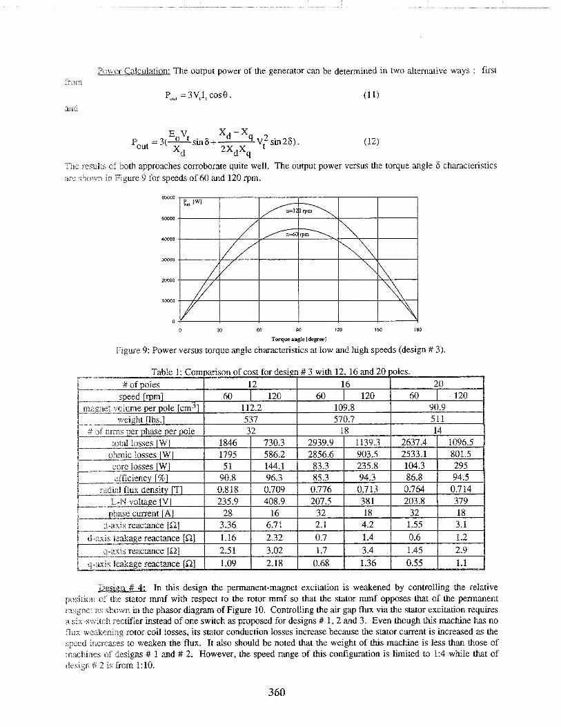
Power Calculation: The output power of the generator can be determined in two alternative ways : first horn
Po,, = 3V,11 cos8, (1 1) <W d
The results of both approaches corroborate quite well. The output power versus the torque angle 6 characteristics ; r e shown in Figure 9 for speeds of 60 ,and 120 rpm.
0
0 30 60 90 120 150 180
Torque angle [degree]
Figure 9: Power versus torque angle characteristics at low and high speeds (design It 3).
In this design the permanent-magnet excitation is weakened by controlling the relative pcssit~on of the stator mmf with respect to the rotor mmf so that the stator mmf opposes that of the pemanent magnet 2s shown in the phasor diagram of Figure 10. Controlling the air gap flux via the stator excitation requires a six-switch rectifier instead of one switch as proposed for designs # 1,2 and 3. Even though this machine has no flux wera4tening rotor coil losses, its stator conduction losses increase because the stator current is increased as the speed increaises to weaken the flux. It also should be noted that the weight of this machine is less than those of macichmes of designs # 1 and # 2. However, the speed range of this configuration is limited to 1:4 while that of design # 2 1s froan 1: 10.
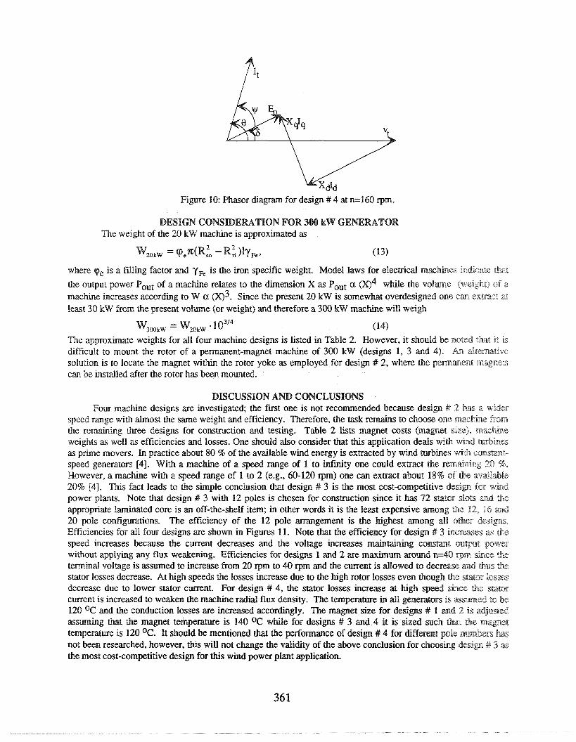
Figure 10: Phasor diagram for design # 4 at n=160 rpm.
DESIGN CONSDERATION FOR 300 kW GENERATOR The weight of the 20 kW machine is approximated as
where cpe is a filling factor and YF, is the iron specific weight. Model laws for electrical machhes a?m&caue &at
the output power Pout of a machine relates to the dimension X as Pout a (w4 wGle the volme (weight) of a machine increases according to W a (w3. Since the present 20 kW is somewhat overdesigned one can extract at least 30 kW from the present volume (or weight) and therefore a 300 kW machine will weigh
Y O O k W = K O k W .1 o3I4 (14)
The approximate weights for all four machine designs is listed in Table 2. However, it should be noted that it rs difficult to mount the rotor of a pemanent-magnet machine of 300 kW (designs 1, 3 and 4). An dteewative solution is to locate the magnet within the rotor yoke as employed for design # 2, where the pem~ment magnets can be installed after the rotor has been mounted.
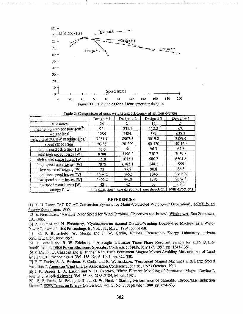
DISCUSSION AND CONCLUSIONS Four machine designs are investigated; the first one is not recommended because design # 2 has a wider
speed range with almost the same weight and efficiency. Therefore, the task remains to choose one m a c k e Prom the remaining three designs for construction and testing. Table 2 lists magnet costs (magnet size), m a c h e weights as well as efficiencies and losses. One should also consider that this application deals with wind mbbes as prime movers. In practice about 80 % of the available wind energy is extracted by wind turbines with cornmu- speed generators 141. With a machine of a speed range of 1 to infmity one could extract the rem~hg 20 %. However, a machine with a speed range of 1 to 2 (e.g., 60-120 rpm) one can extract about 18% of the av~lable 20% [4]. This fact leads to the simple conclusion that design # 3 is the most cost-competitive diesign if01 wind power plants. Note that design # 3 with 12 poles is chosen for consauction since it has 72 s(at(ar slots and the appropriate lminated core is an off-the-shelf item; in other words it is the least expensive m n g the 12, 16 and 20 pole configurations. The efficiency of the 12 pole ement is the highest mong d l other desim. Efficiencies for all four designs are shown in Figures 11. Note that the efficiency for design # 3 h c r a e s as the speed increases because the current decreases and the voltage increases mainh ing consme output power without applying any flux weakening. Efficiencies for designs 1 and 2 are maximm around n--40 vrn shee the terminal voltage is assumed to increase from 20 rpm to 40 rpm and the current is allowed to decreae md thus the stator losses decrease. At high speeds the losses increase due to the high rotor losses even though the $&tor losses decrease due to lower stator current. For design # 4, the stator losses increase at high speed shee the stator current is increased to weaken the machine radial flux density. The temperature in all generators is = w e d to be 120 OC and the conduction losses are increased accordingly. The magnet size for designs # 1 aod 2 is adjusted assurning that the magnet temperature is 140 OC while for designs # 3 and 4 it is sized such that lhe nragnet temperature is 120 OC. It should be mentioned that the performance of design # 4 for different pole n w k s B"m;BP; not been researched, however, this will not change the validity of the above conclusion for choosing design # 3 as the most cost-competitive design for this wind power plant application.
REFERENCES 111 T. H. Lauw, "AC-DC-AC Conversion Systems for Mains-Connected Windpower Generation", ASME Wind
,1988. , 'Variable Rotor Speed for Wind Turbines, Objectives and Issues", Winduower, San Francisco,
CA, 1985. [3] P, Hohes and N. Elsonbatty, "Cycloconverter-Excited Divided-Winding Doubly-Fed Machine as a Wind- Power Convehter", IEEi Proceedings-B, Vol. 131, March 1984, pp. 61-68. 4 C. P. Butterfield, W. Musial and P. W. Carlin, National Renewable Energy Laboratory, private c o m ~ c a s i o n , June 1992. [5] E, Is& and R. W. Erickson, " A Single Transistor Three Phase Resonant Switch for High Quality
, July 1-7,1992, pp. 1341-1351. -Magnet Motors Avoiding Measurement of Load
s with Large Speed
t Magnet Devices",
. Neal, " Starting Performance of Saturable Three-Phase Induction , Vol. 3, No. 3, September 1988, pp. 624-633.
20
10
--
--
0 u speed [fpml , I
0 20 40 60 80 100 120 140 160 180 200
Figure 11: Efficiencies for all four generator designs.
Related Documents