INTERNATIONAL JOURNAL FOR NUMERICAL METHODS IN ENGINEERING Int. J. Numer. Meth. Engng 2005; 62:579–599 Published online 2 December 2004 in Wiley InterScience (www.interscience.wiley.com). DOI: 10.1002/nme.1211 A conforming unified finite element formulation for the vibration of thick beams and frames Spyridon E. Hirdaris 1, ‡ and Arthur W. Lees 2, ∗, † 1 Lloyd’s Register, 71 Fenchurch Street, London, EC3M 4BS, U.K. 2 School of Engineering, University of Wales Swansea, Singleton Park, Swansea, SA2 8PP, U.K. SUMMARY Beams and frames are common features in many engineering structures and in this paper an approach is given to model their dynamic behaviour adequately. Whilst the eigen-frequencies of continuous systems comprising of slender beams can be identified, in most cases of practical interest, by means of Euler or Timoshenko beam theory, for structures comprising of thick beam models this is not necessarily true since such idealizations constrain the cross-sections to remain planar. This paper suggests an alternative approach by means of a unified fully conforming plane stress rectangular finite element which is believed to allow for more realistic representation of the shear effects and hence the strain field around the joints of such structures. The usefulness and functionality of this improved numerical approach is explored via comparison against a non-conforming two-dimensional plate as well as one-dimensional Euler–Bernoulli and Timoshenko finite element formulations corresponding to a variety of beam aspect ratios representing the structures of a rotor and a portal frame. The idealization is shown to be particularly advantageous for simulating the effects of shear distortion where beams join at right angles and the transverse forces in one member interact with the extensional forces of the adjoining structure. Copyright 2004 John Wiley & Sons, Ltd. KEY WORDS: Timoshenko beams; rotors; portal frames; conforming finite elements; dynamic analysis INTRODUCTION Many engineering structures such as ships, aeroplanes, rotors etc. can be modelled with suffi- cient accuracy using beam models and extensive research on the basic theory has spanned almost three centuries. Most of the work is based on the so-called Bernoulli hypothesis according to which structural cross-sections remain planar in the deformed state of the beam ∗ Correspondence to: A. W. Lees, School of Engineering, University of Wales Swansea, Singleton Park, Swansea, SA2 8PP, U.K. † E-mail: [email protected] ‡ This paper describes work undertaken while the first author was engaged in research at the University of Wales Swansea. The paper is published with the permission of Lloyd’s Register but does not necessarily reflect the views of Lloyd’s Register. Received 9 April 2003 Revised 21 April 2004 Copyright 2004 John Wiley & Sons, Ltd. Accepted 5 July 2004

Welcome message from author
This document is posted to help you gain knowledge. Please leave a comment to let me know what you think about it! Share it to your friends and learn new things together.
Transcript
INTERNATIONAL JOURNAL FOR NUMERICAL METHODS IN ENGINEERINGInt. J. Numer. Meth. Engng 2005; 62:579–599Published online 2 December 2004 in Wiley InterScience (www.interscience.wiley.com). DOI: 10.1002/nme.1211
A conforming unified finite element formulation for thevibration of thick beams and frames
Spyridon E. Hirdaris1,‡ and Arthur W. Lees2,∗,†
1Lloyd’s Register, 71 Fenchurch Street, London, EC3M 4BS, U.K.2School of Engineering, University of Wales Swansea, Singleton Park, Swansea, SA2 8PP, U.K.
SUMMARY
Beams and frames are common features in many engineering structures and in this paper an approachis given to model their dynamic behaviour adequately. Whilst the eigen-frequencies of continuoussystems comprising of slender beams can be identified, in most cases of practical interest, by meansof Euler or Timoshenko beam theory, for structures comprising of thick beam models this is notnecessarily true since such idealizations constrain the cross-sections to remain planar. This papersuggests an alternative approach by means of a unified fully conforming plane stress rectangular finiteelement which is believed to allow for more realistic representation of the shear effects and hencethe strain field around the joints of such structures. The usefulness and functionality of this improvednumerical approach is explored via comparison against a non-conforming two-dimensional plate aswell as one-dimensional Euler–Bernoulli and Timoshenko finite element formulations correspondingto a variety of beam aspect ratios representing the structures of a rotor and a portal frame. Theidealization is shown to be particularly advantageous for simulating the effects of shear distortionwhere beams join at right angles and the transverse forces in one member interact with the extensionalforces of the adjoining structure. Copyright � 2004 John Wiley & Sons, Ltd.
KEY WORDS: Timoshenko beams; rotors; portal frames; conforming finite elements; dynamic analysis
INTRODUCTION
Many engineering structures such as ships, aeroplanes, rotors etc. can be modelled with suffi-cient accuracy using beam models and extensive research on the basic theory has spannedalmost three centuries. Most of the work is based on the so-called Bernoulli hypothesisaccording to which structural cross-sections remain planar in the deformed state of the beam
∗Correspondence to: A. W. Lees, School of Engineering, University of Wales Swansea, Singleton Park, Swansea,SA2 8PP, U.K.
†E-mail: [email protected]‡This paper describes work undertaken while the first author was engaged in research at the University ofWales Swansea. The paper is published with the permission of Lloyd’s Register but does not necessarily reflectthe views of Lloyd’s Register.
Received 9 April 2003Revised 21 April 2004
Copyright � 2004 John Wiley & Sons, Ltd. Accepted 5 July 2004
580 S. E. HIRDARIS AND A. W. LEES
but differ in the way the relationships between the displacements, rotations and correspondingstrain measures are defined.
Euler’s ‘Elastica’ [1] denotes a planar beam with no axial and shear strains so that thebending stresses couple, being proportional to the curvature, while the Kirchhoff’s beam [2]consists a spatial generalization of the former with the torsional stress couple being proportionalto the torsional curvature. When some small axial strain is added the Kirchhoff–Love beamtheory [3] is being used to simulate the structure sufficiently. Due to the absence of shear strainsat the centroid of each plane of the structure in all of these theories the cross-sections remainorthogonal to the neutral axis of the beam. In contrast, the presence of shear strains introducesa change of the angle between a cross-section and the centroidal axis, so that the deformedconfiguration of a beam is defined by the deformed centroidal axis and the set of orientationsof cross-sections with respect to their un-deformed position. Such a beam, in which the fieldsof lateral displacements and rotations are considered as independent, is generally referred asthe Timoshenko beam [4, 5].
Although the Euler equation comprises a good representation of the modal behaviour of aslender beam, at lower aspect ratios the Timoshenko theory, involving shear and rotary inertiaeffects, provides a better description. But even this improved representation has only a limitedrange of applications for continuous systems comprising of thick beam models. At lower aspectratios the structure deviates from its fundamental beam properties and the accuracy of the so-called shear correction coefficient (k), introduced to account for the shear stress distributionover the cross-section of the beam, is dependent upon the material and geometric parametersas well as the loading and boundary conditions of the structure under consideration [6].
A first cure of that problem could be the introduction of a consistent higher-order beamtheory accounting for the parabolic distribution of the transverse shear strain via expansionof the axial displacement of a point on the beam cross-section as a cubic function of thebeam thickness co-ordinate. Such analytical formulations have been introduced in the past byJemielita [7], Levinson [8], Bickford [9] and Reddy [10, 11]. Since the displacement field usedin these theories accommodates for the quadratic variation and the vanishing of transverse shearstrain on the top and bottom planes of the beam, there is no need to use shear correctionfactors.
However, the solution of complicated problems in beam bending by means of analyticalmodels is particularly tedious and understanding is frequently improved by means of approx-imate and numerical techniques. The finite element equations for the Bernoulli–Euler andTimoshenko theories are well established in literature [12–14]. Some interesting higher-orderone-dimensional beam finite element formulations have also been proposed initially by Thomaset al. [15, 16] and Lees and Thomas [17] and later by Heyliger and Reddy [18]. Without anydoubt the representation by means of beams gives considerable savings in the dimensionalityof the problems as compared to the study of a fully three-dimensional system. However, thesesavings are made at a price and it is important to appreciate the approximations involved andtheir range of applicability. Such an understanding is important in both the original modellingof a system and in the application of updating techniques to match a model with the observedbehaviour.
Based on the experience gained from preliminary investigations [19–21], in this paper it issuggested that the use of a unified, fully conforming, four noded, plate finite element formula-tion with 32 degrees of freedom could improve our understanding with regards to the dynamicbehaviour of continuous systems comprising of thick beam models. The idealization is used to
Copyright � 2004 John Wiley & Sons, Ltd. Int. J. Numer. Meth. Engng 2005; 62:579–599
CONFORMING UNIFIED FINITE ELEMENT FORMULATION 581
analyse two systems which although simple, have wide practical application. The first of theseis a stepped cantilever. The motivation for this example comes from rotor dynamics wherereal rotors are, almost invariably, composed of lengths with varying cross-section. The secondarea explored is the case in which beams meet at right angles and hence the transverse forcesin one member interact with the extensional forces of the adjoining beam. The most trivialinstance of this is the case of a portal frame. This is simple yet of wide general importancein structural dynamics, not least in the supporting structures for large rotating machines. Two-dimensional conforming and non-conforming finite element idealizations are compared againstone-dimensional beam element models of Euler–Bernoulli and Timoshenko forms for a vari-ety of aspect ratios. From the analyses it becomes apparent that that at those nodal locationsand slenderness aspect ratios where shear effects become important, two-dimensional ideal-izations could become necessary to achieve reliable results. In particular a fully conformingfinite element idealization could become particularly beneficial in approximating successfullythe fundamental modal values of frame models where the shear distortion causes significantdiscrepancies between the angles of rotation of the adjoining structural members.
EULER–BERNOULLI AND TIMOSHENKO BEAM THEORIES
In the Bernoulli–Euler theory of flexural vibrations of beams only the transverse inertia andelastic forces due to bending deflections are considered [22]. However, as the ratio of thedepth of the beam to the wavelength of vibration increases this mathematical model tends tooverestimate the frequency and consequently, Timoshenko’s beam theory, which assumes thatthe rotation of the cross-section is considered as the sum of the shearing angle and the rotationof the neutral axis [15, 17, 22, 23], is employed. Being concerned only with the extraction ofthe natural frequencies and principal modes and by excluding all forcing and damping terms,the equations of motion describing the dynamics of a uniform Timoshenko takes the form
EI�4
u
�x4+ �2
[Iz +
EI�kAG
]�2
u
�x2− EI�z�2
r
kAG
�2�
�x2− ��2
r[u − z�] +�Iz�4
r
kAG[u − z�] = 0 (1)
where, Iz(= �I) is the rotary inertia term, I the vertical moment of inertia of the system, Gthe shear modulus, A the cross-sectional area, and k the Timoshenko’s shear coefficient whichtakes account of the shape of the cross-section. The terms EI and kAG are known as flexuraland shear rigidity respectively, while z represents the distance between the shear and gravitycentres.
BASIC TIMOSHENKO BEAM ELEMENTS
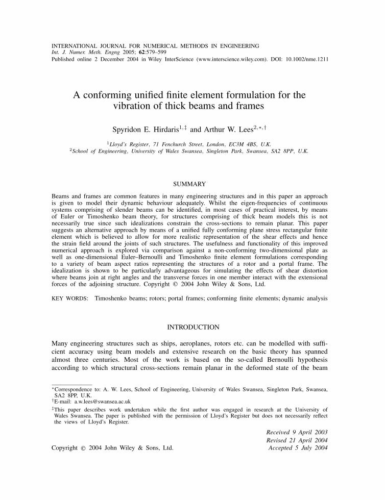
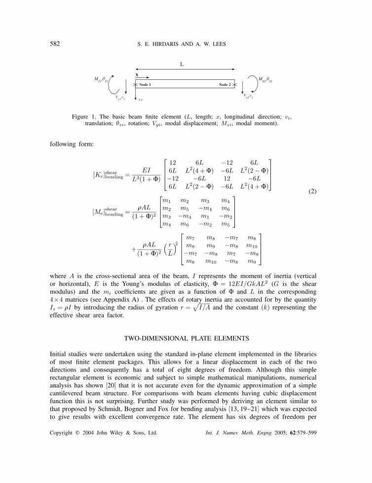
In literature the simplest beam element derived by following this approach is the one simulatinga uniform Euler beam with two nodal points and two degrees of freedom (one translation andone rotation) per node as shown in Figure 1.
Przemieniecki [12,13] provides a derivation of the stiffness and mass matrices of a uniformTimoshenko beam via inclusion of the effects of rotary inertia and shear deformation in the
Copyright � 2004 John Wiley & Sons, Ltd. Int. J. Numer. Meth. Engng 2005; 62:579–599
582 S. E. HIRDARIS AND A. W. LEES
L
MZ1
,�Z1
MZ2
,�Z2
Vy2
,v2V
y1,v
1
x
y,v
Node 1 Node 2
Figure 1. The basic beam finite element (L, length; x, longitudinal direction; vi,translation; �zi, rotation; Vyi, modal displacement; Mzi, modal moment).
following form:
[Ke]shearbending =
EI
L3(1 + �)
12 6L −12 6L6L L2(4 + �) −6L L2(2 − �)−12 −6L 12 −6L6L L2(2 − �) −6L L2(4 + �)
(2)
[Me]shearbending =
�AL
(1 + �)2
m1 m2 m3 m4m2 m5 −m4 m6m3 −m4 m1 −m2m4 m6 −m2 m5
+�AL
(1 + �)2( r
L
)2
m7 m8 −m7 m8m8 m9 −m8 m10
−m7 −m8 m7 −m8m8 m10 −m8 m9
where A is the cross-sectional area of the beam, I represents the moment of inertia (verticalor horizontal), E is the Young’s modulus of elasticity, � = 12EI/GkAL2 (G is the shearmodulus) and the mi coefficients are given as a function of � and L in the corresponding4×4 matrices (see Appendix A) . The effects of rotary inertia are accounted for by the quantityIz = �I by introducing the radius of gyration r =
√I/A and the constant (k) representing the
effective shear area factor.
TWO-DIMENSIONAL PLATE ELEMENTS
Initial studies were undertaken using the standard in-plane element implemented in the librariesof most finite element packages. This allows for a linear displacement in each of the twodirections and consequently has a total of eight degrees of freedom. Although this simplerectangular element is economic and subject to simple mathematical manipulations, numericalanalysis has shown [20] that it is not accurate even for the dynamic approximation of a simplecantilevered beam structure. For comparisons with beam elements having cubic displacementfunction this is not surprising. Further study was performed by deriving an element similar tothat proposed by Schmidt, Bogner and Fox for bending analysis [13, 19–21] which was expectedto give results with excellent convergence rate. The element has six degrees of freedom per
Copyright � 2004 John Wiley & Sons, Ltd. Int. J. Numer. Meth. Engng 2005; 62:579–599
CONFORMING UNIFIED FINITE ELEMENT FORMULATION 583
Assumptions
Equilibrium Compatibility
Stress-strain Law
Relationship between applied forces and stresses
Relationship between displacements and strains
1
23
4
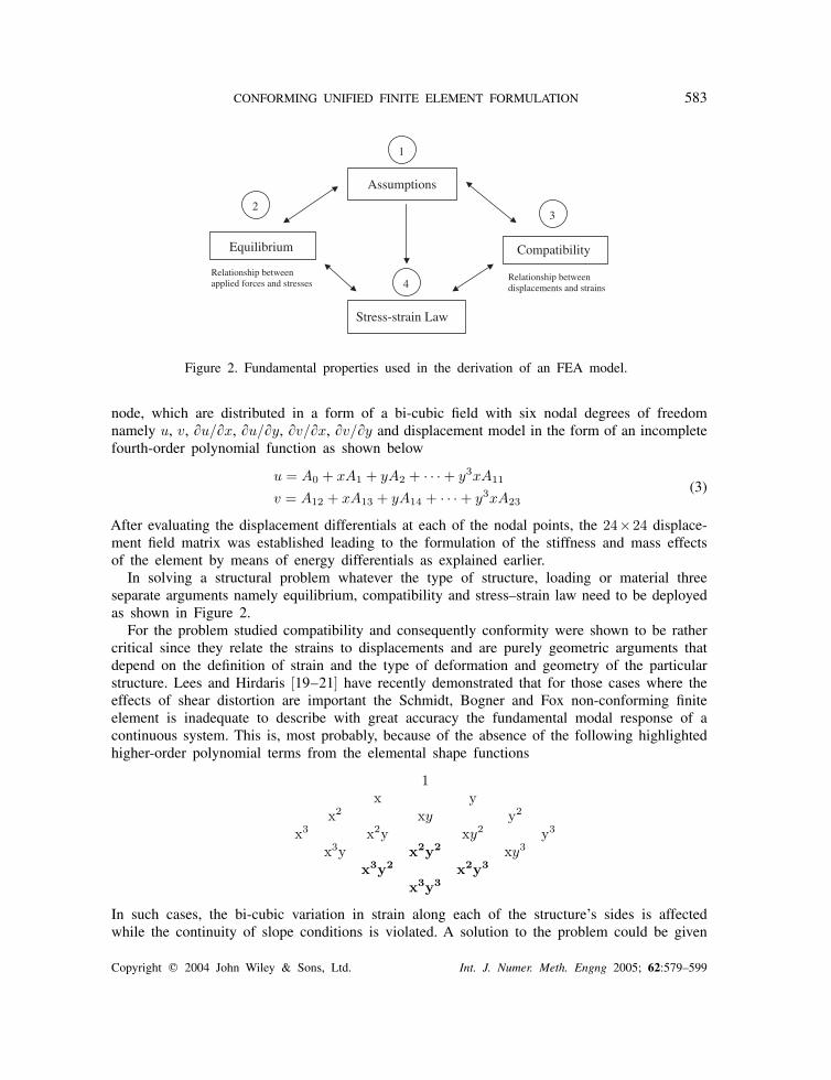
Figure 2. Fundamental properties used in the derivation of an FEA model.
node, which are distributed in a form of a bi-cubic field with six nodal degrees of freedomnamely u, v, �u/�x, �u/�y, �v/�x, �v/�y and displacement model in the form of an incompletefourth-order polynomial function as shown below
u = A0 + xA1 + yA2 + · · · + y3xA11
v = A12 + xA13 + yA14 + · · · + y3xA23(3)
After evaluating the displacement differentials at each of the nodal points, the 24×24 displace-ment field matrix was established leading to the formulation of the stiffness and mass effectsof the element by means of energy differentials as explained earlier.
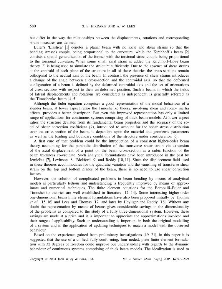
In solving a structural problem whatever the type of structure, loading or material threeseparate arguments namely equilibrium, compatibility and stress–strain law need to be deployedas shown in Figure 2.
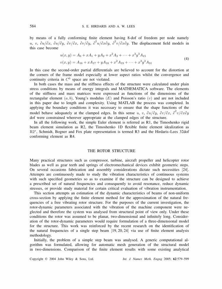
For the problem studied compatibility and consequently conformity were shown to be rathercritical since they relate the strains to displacements and are purely geometric arguments thatdepend on the definition of strain and the type of deformation and geometry of the particularstructure. Lees and Hirdaris [19–21] have recently demonstrated that for those cases where theeffects of shear distortion are important the Schmidt, Bogner and Fox non-conforming finiteelement is inadequate to describe with great accuracy the fundamental modal response of acontinuous system. This is, most probably, because of the absence of the following highlightedhigher-order polynomial terms from the elemental shape functions
1x y
x2 xy y2
x3 x2y xy2 y3
x3y x2y2 xy3
x3y2 x2y3
x3y3
In such cases, the bi-cubic variation in strain along each of the structure’s sides is affectedwhile the continuity of slope conditions is violated. A solution to the problem could be given
Copyright � 2004 John Wiley & Sons, Ltd. Int. J. Numer. Meth. Engng 2005; 62:579–599
584 S. E. HIRDARIS AND A. W. LEES
by means of a fully conforming finite element having 8-dof of freedom per node namelyu, v, �u/�x, �u/�y, �v/�x, �v/�y, �2
u/�x�y, �2v/�x�y. The displacement field models in
this case become
u(x, y) = A0 + xA1 + yA2 + x2A3 + · · · + x3y3A15
v(x, y) = A16 + xA17 + yA18 + x2A19 + · · · + x3y3A31(4)
In this case the second-order partial differentials are believed to account for the distortion atthe corners of the frame model especially at lower aspect ratios whilst the convergence andcontinuity criteria in C0 space are not violated.
In both cases the mass and the stiffness effects of the structure were calculated under plainstress conditions by means of energy integrals and MATHEMATICA software. The elementsof the stiffness and mass matrices were expressed as functions of the dimensions of therectangular element (a, b), Young’s modulus (E) and Poisson’s ratio (v) and are not includedin this paper due to length and complexity. Using MATLAB the process was completed. Inapplying the boundary conditions it was necessary to ensure that the shape functions of themodel behave adequately at the clamped edges. In this sense u, v, �u/�y, �v/�x, �2
v/�x�ydof were constrained wherever appropriate at the clamped edges of the structure.
In all the following work, the simple Euler element is referred as R1, the Timoshenko rigidbeam element simulation as R2, the Timoshenko 1D flexible finite element idealization asR2∗, Schmidt, Bogner and Fox plate representation is termed R3 and the Hirdaris–Lees 32dofconforming element as R4.
THE ROTOR STRUCTURE
Many practical structures such as compressor, turbine, aircraft propeller and helicopter rotorblades as well as gear teeth and springs of electromechanical devices exhibit geometric steps.On several occasions fabrication and assembly considerations dictate such necessities [24].Attempts are continuously made to study the vibration characteristics of continuous systemswith such specified geometries so as to examine if the structure can be designed to achievea prescribed set of natural frequencies and consequently to avoid resonance, reduce dynamicstresses, or provide study material for certain critical evaluation of vibration instrumentation.
This section attempts an estimation of the dynamic characteristics of beams of non-uniformcross-section by applying the finite element method for the approximation of the natural fre-quencies of a free vibrating rotor structure. For the purposes of the current investigation, therotor-dynamic parameters associated with the vibration of the machine component were ne-glected and therefore the system was analysed from structural point of view only. Under theseconditions the rotor was assumed to be planar, two-dimensional and infinitely long. Consider-ation of the rotor-dynamic parameters would require formulation of a three-dimensional modelfor the structure. This work was reinforced by the recent research on the identification ofthe natural frequencies of a single step beam [19, 20, 24] via use of finite element analysismethodology.
Initially, the problem of a simple step beam was analysed. A generic computational al-gorithm was formulated, allowing for automatic mesh generation of the structural modelin two-dimensions. Comparison of the finite element results with some existing analytical
Copyright � 2004 John Wiley & Sons, Ltd. Int. J. Numer. Meth. Engng 2005; 62:579–599
CONFORMING UNIFIED FINITE ELEMENT FORMULATION 585
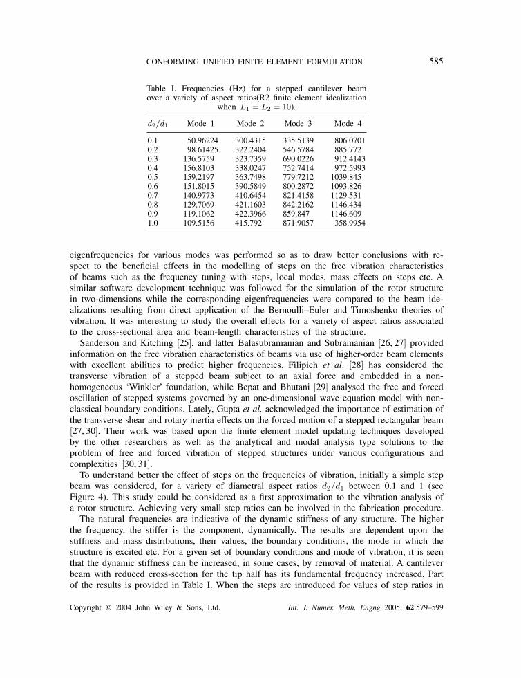
Table I. Frequencies (Hz) for a stepped cantilever beamover a variety of aspect ratios(R2 finite element idealization
when L1 = L2 = 10).
d2/d1 Mode 1 Mode 2 Mode 3 Mode 4
0.1 50.96224 300.4315 335.5139 806.07010.2 98.61425 322.2404 546.5784 885.7720.3 136.5759 323.7359 690.0226 912.41430.4 156.8103 338.0247 752.7414 972.59930.5 159.2197 363.7498 779.7212 1039.8450.6 151.8015 390.5849 800.2872 1093.8260.7 140.9773 410.6454 821.4158 1129.5310.8 129.7069 421.1603 842.2162 1146.4340.9 119.1062 422.3966 859.847 1146.6091.0 109.5156 415.792 871.9057 358.9954
eigenfrequencies for various modes was performed so as to draw better conclusions with re-spect to the beneficial effects in the modelling of steps on the free vibration characteristicsof beams such as the frequency tuning with steps, local modes, mass effects on steps etc. Asimilar software development technique was followed for the simulation of the rotor structurein two-dimensions while the corresponding eigenfrequencies were compared to the beam ide-alizations resulting from direct application of the Bernoulli–Euler and Timoshenko theories ofvibration. It was interesting to study the overall effects for a variety of aspect ratios associatedto the cross-sectional area and beam-length characteristics of the structure.
Sanderson and Kitching [25], and latter Balasubramanian and Subramanian [26, 27] providedinformation on the free vibration characteristics of beams via use of higher-order beam elementswith excellent abilities to predict higher frequencies. Filipich et al. [28] has considered thetransverse vibration of a stepped beam subject to an axial force and embedded in a non-homogeneous ‘Winkler’ foundation, while Bepat and Bhutani [29] analysed the free and forcedoscillation of stepped systems governed by an one-dimensional wave equation model with non-classical boundary conditions. Lately, Gupta et al. acknowledged the importance of estimation ofthe transverse shear and rotary inertia effects on the forced motion of a stepped rectangular beam[27, 30]. Their work was based upon the finite element model updating techniques developedby the other researchers as well as the analytical and modal analysis type solutions to theproblem of free and forced vibration of stepped structures under various configurations andcomplexities [30, 31].
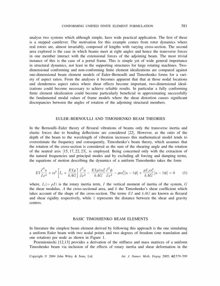
To understand better the effect of steps on the frequencies of vibration, initially a simple stepbeam was considered, for a variety of diametral aspect ratios d2/d1 between 0.1 and 1 (seeFigure 4). This study could be considered as a first approximation to the vibration analysis ofa rotor structure. Achieving very small step ratios can be involved in the fabrication procedure.
The natural frequencies are indicative of the dynamic stiffness of any structure. The higherthe frequency, the stiffer is the component, dynamically. The results are dependent upon thestiffness and mass distributions, their values, the boundary conditions, the mode in which thestructure is excited etc. For a given set of boundary conditions and mode of vibration, it is seenthat the dynamic stiffness can be increased, in some cases, by removal of material. A cantileverbeam with reduced cross-section for the tip half has its fundamental frequency increased. Partof the results is provided in Table I. When the steps are introduced for values of step ratios in
Copyright � 2004 John Wiley & Sons, Ltd. Int. J. Numer. Meth. Engng 2005; 62:579–599
586 S. E. HIRDARIS AND A. W. LEES
E1, I
1E
2, I
2
L1
L 2 = L / 2
L
d2d
1
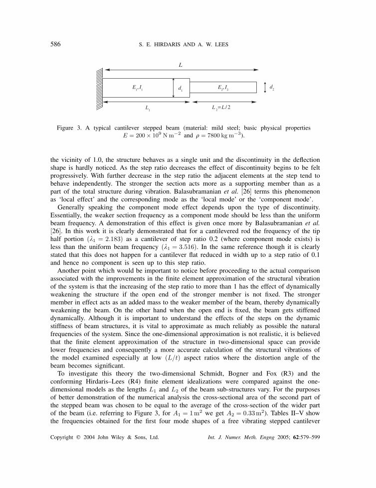
Figure 3. A typical cantilever stepped beam (material: mild steel; basic physical propertiesE = 200 × 109 N m−2 and � = 7800 kg m−3).
the vicinity of 1.0, the structure behaves as a single unit and the discontinuity in the deflectionshape is hardly noticed. As the step ratio decreases the effect of discontinuity begins to be feltprogressively. With further decrease in the step ratio the adjacent elements at the step tend tobehave independently. The stronger the section acts more as a supporting member than as apart of the total structure during vibration. Balasubramanian et al. [26] terms this phenomenonas ‘local effect’ and the corresponding mode as the ‘local mode’ or the ‘component mode’.
Generally speaking the component mode effect depends upon the type of discontinuity.Essentially, the weaker section frequency as a component mode should be less than the uniformbeam frequency. A demonstration of this effect is given once more by Balasubramanian et al.[26]. In this work it is clearly demonstrated that for a cantilevered rod the frequency of the tiphalf portion (�1 = 2.183) as a cantilever of step ratio 0.2 (where component mode exists) isless than the uniform beam frequency (�1 = 3.516). In the same reference though it is clearlystated that this does not happen for a cantilever flat reduced in width up to a step ratio of 0.1and hence no component is seen up to this step ratio.
Another point which would be important to notice before proceeding to the actual comparisonassociated with the improvements in the finite element approximation of the structural vibrationof the system is that the increasing of the step ratio to more than 1 has the effect of dynamicallyweakening the structure if the open end of the stronger member is not fixed. The strongermember in effect acts as an added mass to the weaker member of the beam, thereby dynamicallyweakening the beam. On the other hand when the open end is fixed, the beam gets stiffeneddynamically. Although it is important to understand the effects of the steps on the dynamicstiffness of beam structures, it is vital to approximate as much reliably as possible the naturalfrequencies of the system. Since the one-dimensional approximation is not realistic, it is believedthat the finite element approximation of the structure in two-dimensional space can providelower frequencies and consequently a more accurate calculation of the structural vibrations ofthe model examined especially at low (L/t) aspect ratios where the distortion angle of thebeam becomes significant.
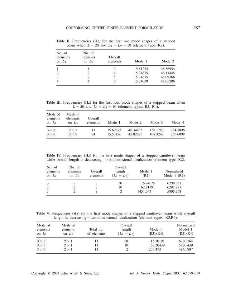
To investigate this theory the two-dimensional Schmidt, Bogner and Fox (R3) and theconforming Hirdaris–Lees (R4) finite element idealizations were compared against the one-dimensional models as the lengths L1 and L2 of the beam sub-structures vary. For the purposesof better demonstration of the numerical analysis the cross-sectional area of the second part ofthe stepped beam was chosen to be equal to the average of the cross-section of the wider partof the beam (i.e. referring to Figure 3, for A1 = 1m2 we get A2 = 0.33m2). Tables II–V showthe frequencies obtained for the first four mode shapes of a free vibrating stepped cantilever
Copyright � 2004 John Wiley & Sons, Ltd. Int. J. Numer. Meth. Engng 2005; 62:579–599
CONFORMING UNIFIED FINITE ELEMENT FORMULATION 587
Table II. Frequencies (Hz) for the first two mode shapes of a steppedbeam when L = 20 and L1 = L2 = 10 (element type: R2).
No. of No. ofelements elements Overallon L1 on L2 elements Mode 1 Mode 2
1 1 2 15.81234 48.569542 2 4 15.74675 48.114453 2 5 15.74675 48.093664 4 8 15.74039 48.05206
Table III. Frequencies (Hz) for the first four mode shapes of a stepped beam whenL = 20 and L1 = L2 = 10 (element types: R3, R4).
Mesh of Mesh ofelements elements Overallon L1 on L2 elements Mode 1 Mode 2 Mode 3 Mode 4
3 × 3 2 × 1 11 15.69873 46.34835 138.1789 284.70963 × 6 3 × 2 24 15.53126 45.82925 108.3247 265.6008
Table IV. Frequencies (Hz) for the first mode shapes of a stepped cantilever beamwhile overall length is decreasing—one-dimensional idealization (element type: R2).
No. of No. of Overallelements elements Overall length Mode 1 Normalizedon L1 on L2 elements (L1 = L2) (R2) Mode 1 (R2)
3 2 8 20 15.74675 6298.6513 2 8 10 62.81791 6281.7913 2 8 2 1451.343 5805.368
Table V. Frequencies (Hz) for the first mode shapes of a stepped cantilever beam while overalllength is decreasing—two-dimensional idealization (element types: R3,R4).
Mesh of Mesh of Overall Normalizedelements elements Total no. length Mode 1 Model 1on L1 on L2 of elements (L1 = L2) (R3),(R4) (R3),(R4)
3 × 3 2 × 1 11 20 15.70191 6280.7643 × 3 2 × 1 11 10 59.20439 5920.4393 × 3 2 × 1 11 2 1236.473 4945.887
Copyright � 2004 John Wiley & Sons, Ltd. Int. J. Numer. Meth. Engng 2005; 62:579–599
588 S. E. HIRDARIS AND A. W. LEES
L1
L2
L3
d
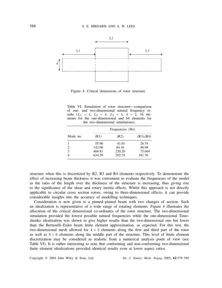
Figure 4. Critical dimensions of rotor structure.
Table VI. Simulation of rotor structure—comparisonof one- and two-dimensional natural frequency re-sults (L1 = 4, L2 = 8, L3 = 4, d = 2, 16 ele-ments for the one-dimensional and 64 elements for
the two-dimensional simulations).
Frequencies (Hz)
Mode no. (R1) (R2) (R3),(R4)
1 55.96 41.01 26.742 142.96 84.16 40.983 404.81 220.20 75.0444 634.59 292.74 181.76
structure when this is discretized by R2, R3 and R4 elements respectively. To demonstrate theeffect of increasing beam thickness it was convenient to evaluate the frequencies of the modelas the ratio of the length over the thickness of the structure is increasing, thus giving riseto the significance of the shear and rotary inertia effects. Whilst this approach is not directlyapplicable to circular cross section rotors, owing to three-dimensional effects, it can provideconsiderable insights into the accuracy of modelling techniques.
Consideration is now given to a pinned–pinned beam with two changes of section. Suchan idealization is representative of a wide range of rotating elements. Figure 4 illustrates theallocation of the critical dimensional co-ordinates of the rotor structure. The two-dimensionalsimulation provided the lowest possible natural frequencies while the one-dimensional Timo-shenko idealization was shown to give higher results than the two-dimensional one but lowerthan the Bernoulli–Euler beam finite element approximation, as expected. For this test, thetwo-dimensional mesh allowed for 4 × 2 elements along the first and third part of the rotoras well as 8 × 6 elements along the middle part of the structure. This level of finite elementdiscretization may be considered as realistic from a numerical analysis point of view (seeTable VI). It is rather interesting to note that conforming and non-conforming two-dimensionalfinite element idealizations provided identical results even at lower aspect ratios.
Copyright � 2004 John Wiley & Sons, Ltd. Int. J. Numer. Meth. Engng 2005; 62:579–599
CONFORMING UNIFIED FINITE ELEMENT FORMULATION 589
THE FRAME STRUCTURE
The problem of flexural vibrations of frames is of primary importance in engineering designpractice. As expected, there has been extensive research into the vibration of such systemsin many different configurations and complexities. The majority of the work has been in thearea of what is described as closed frames [32]. Some representative examples include theRayleigh–Ritz treatment of a portal frame under support conditions that range from clampedor pinned [32–34] to elastically supported. The latter is due to Filipich et al. [35], in case ofsymmetric vibrations and to Laura and Valerga de Greco [36], in the case of anitisymmetricdynamics. These cases have also been treated by using a more analytical approach by Filipichand Laura [37]. Portal frames with cross bracing including axial deformation in the memberswere investigated by Chang et al. [38], while Mottershead et al. [39] have reported on theexperimental identification of portal frame dynamics. More recently, Lee and Ng [40] haveused the Rayleigh–Ritz method to treat portal frames, H frames and T frames. Clough andPenzien [14] include a two member closed frame as an example. Alexandropoulos et al. [41]analysed the free vibration of a closed two bar frame carrying a concentrated mass capturingthe dynamic couplings of the system precisely.
In considering the effects of longitudinal vibration on the lateral vibration eigen-frequenciesthe mass of the portal frame joints as well as the shear effects have to be considered. For thosecases where beams join at right angles three significant factors namely (i) the mass distribution,(ii) the shear distortion of the joints and (iii) the shear coefficient for the rigid structure shouldbe considered in the one-dimensional simulations. The first one is associated with the designand manufacturing of the structure and it should be realistically justified when comparing theone-dimensional rigid frame against the two-dimensional planar frame finite element model.
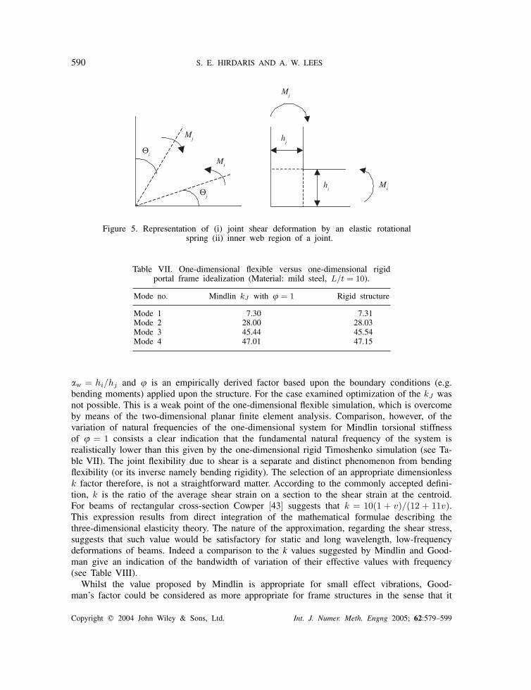
The shear distortion of the joints is a measure of the extent to which the representation ofthe distortion angles at the frame corners is realistic. Physically frames are not rigid in thesense that a bending moment is transmitted at the corners of the structure. Hence, the sheardistortion causes a discrepancy between the angles of rotation of the two beam ends, thusfailing to fulfil the assumption of a unique value of nodal rotation. To a first approximation themagnitude of the discrepancy in the angles is equal to the overall mean value of shear strainat the web region, �w. If the beams are relatively short the joint flexibility arising from sheardistortion contributes significantly to the overall flexibility of the frame, and must be accountedfor in order to obtain accurate values of bending moments, especially at the vicinity of thejoints. For the simple, (unbraced) structure examined, an insertion of a very stiff rotationalspring connecting the two beams could provide a linear elastic moment resisting any increaseor decrease in the angle of the joint. The spring is not an ‘element’ in the usual sense, becauseit has no physical size, but it does connect two independent degrees of freedom (�i, �j) andit supplies rotational stiffness between them (see Figure 5). It therefore may be incorporatedin the 1D finite element model by means of a 2 × 2 stiffness matrix having the same form of
that of a linear spring k = kJ
[1 −1
−1 1
], where kJ is the spring stiffness of the joint defined
as the net total moment acting on the joint divided by the resulting shear angle.Although the exact distribution shear strain would depend on the local geometry, an approx-
imate qualitative estimate of the joint stiffness on the basis of the mean value of shear stresswithin the joint region could be obtained. Hughes [42], has shown that for a joint subject toapplied moments Mi, Mj the joint stiffness is given by kJ = �Gtwhihj/(w + (1/w)), where
Copyright � 2004 John Wiley & Sons, Ltd. Int. J. Numer. Meth. Engng 2005; 62:579–599
590 S. E. HIRDARIS AND A. W. LEES
Θi
Θj
Mj
Mi
Mj
Mi
hj
hi
Figure 5. Representation of (i) joint shear deformation by an elastic rotationalspring (ii) inner web region of a joint.
Table VII. One-dimensional flexible versus one-dimensional rigidportal frame idealization (Material: mild steel, L/t = 10).
Mode no. Mindlin kJ with � = 1 Rigid structure
Mode 1 7.30 7.31Mode 2 28.00 28.03Mode 3 45.44 45.54Mode 4 47.01 47.15
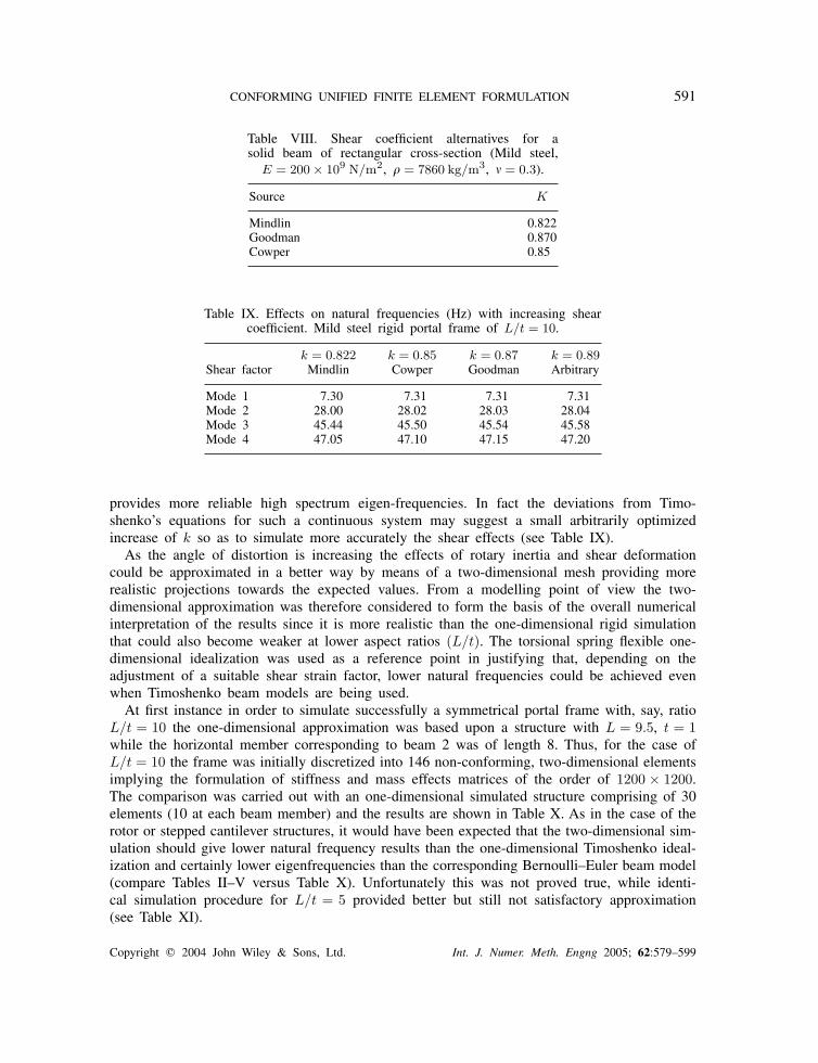
w = hi/hj and � is an empirically derived factor based upon the boundary conditions (e.g.bending moments) applied upon the structure. For the case examined optimization of the kJ wasnot possible. This is a weak point of the one-dimensional flexible simulation, which is overcomeby means of the two-dimensional planar finite element analysis. Comparison, however, of thevariation of natural frequencies of the one-dimensional system for Mindlin torsional stiffnessof � = 1 consists a clear indication that the fundamental natural frequency of the system isrealistically lower than this given by the one-dimensional rigid Timoshenko simulation (see Ta-ble VII). The joint flexibility due to shear is a separate and distinct phenomenon from bendingflexibility (or its inverse namely bending rigidity). The selection of an appropriate dimensionlessk factor therefore, is not a straightforward matter. According to the commonly accepted defini-tion, k is the ratio of the average shear strain on a section to the shear strain at the centroid.For beams of rectangular cross-section Cowper [43] suggests that k = 10(1 + v)/(12 + 11v).This expression results from direct integration of the mathematical formulae describing thethree-dimensional elasticity theory. The nature of the approximation, regarding the shear stress,suggests that such value would be satisfactory for static and long wavelength, low-frequencydeformations of beams. Indeed a comparison to the k values suggested by Mindlin and Good-man give an indication of the bandwidth of variation of their effective values with frequency(see Table VIII).
Whilst the value proposed by Mindlin is appropriate for small effect vibrations, Good-man’s factor could be considered as more appropriate for frame structures in the sense that it
Copyright � 2004 John Wiley & Sons, Ltd. Int. J. Numer. Meth. Engng 2005; 62:579–599
CONFORMING UNIFIED FINITE ELEMENT FORMULATION 591
Table VIII. Shear coefficient alternatives for asolid beam of rectangular cross-section (Mild steel,
E = 200 × 109 N/m2, � = 7860 kg/m3, = 0.3).
Source K
Mindlin 0.822Goodman 0.870Cowper 0.85
Table IX. Effects on natural frequencies (Hz) with increasing shearcoefficient. Mild steel rigid portal frame of L/t = 10.
k = 0.822 k = 0.85 k = 0.87 k = 0.89Shear factor Mindlin Cowper Goodman Arbitrary
Mode 1 7.30 7.31 7.31 7.31Mode 2 28.00 28.02 28.03 28.04Mode 3 45.44 45.50 45.54 45.58Mode 4 47.05 47.10 47.15 47.20
provides more reliable high spectrum eigen-frequencies. In fact the deviations from Timo-shenko’s equations for such a continuous system may suggest a small arbitrarily optimizedincrease of k so as to simulate more accurately the shear effects (see Table IX).
As the angle of distortion is increasing the effects of rotary inertia and shear deformationcould be approximated in a better way by means of a two-dimensional mesh providing morerealistic projections towards the expected values. From a modelling point of view the two-dimensional approximation was therefore considered to form the basis of the overall numericalinterpretation of the results since it is more realistic than the one-dimensional rigid simulationthat could also become weaker at lower aspect ratios (L/t). The torsional spring flexible one-dimensional idealization was used as a reference point in justifying that, depending on theadjustment of a suitable shear strain factor, lower natural frequencies could be achieved evenwhen Timoshenko beam models are being used.
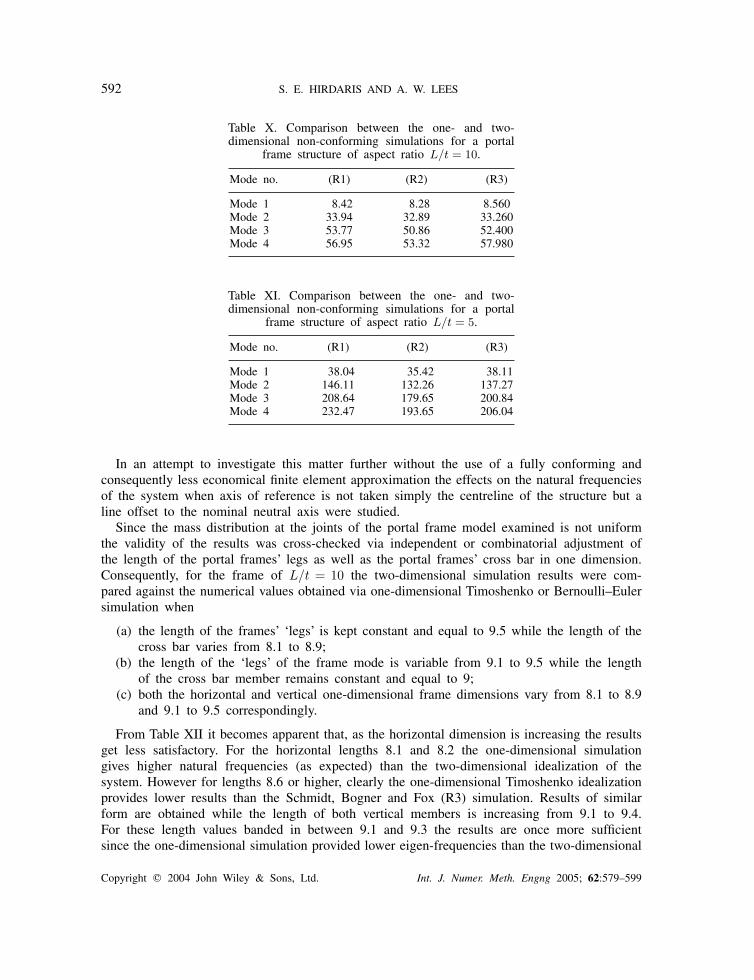
At first instance in order to simulate successfully a symmetrical portal frame with, say, ratioL/t = 10 the one-dimensional approximation was based upon a structure with L = 9.5, t = 1while the horizontal member corresponding to beam 2 was of length 8. Thus, for the case ofL/t = 10 the frame was initially discretized into 146 non-conforming, two-dimensional elementsimplying the formulation of stiffness and mass effects matrices of the order of 1200 × 1200.The comparison was carried out with an one-dimensional simulated structure comprising of 30elements (10 at each beam member) and the results are shown in Table X. As in the case of therotor or stepped cantilever structures, it would have been expected that the two-dimensional sim-ulation should give lower natural frequency results than the one-dimensional Timoshenko ideal-ization and certainly lower eigenfrequencies than the corresponding Bernoulli–Euler beam model(compare Tables II–V versus Table X). Unfortunately this was not proved true, while identi-cal simulation procedure for L/t = 5 provided better but still not satisfactory approximation(see Table XI).
Copyright � 2004 John Wiley & Sons, Ltd. Int. J. Numer. Meth. Engng 2005; 62:579–599
592 S. E. HIRDARIS AND A. W. LEES
Table X. Comparison between the one- and two-dimensional non-conforming simulations for a portal
frame structure of aspect ratio L/t = 10.
Mode no. (R1) (R2) (R3)
Mode 1 8.42 8.28 8.560Mode 2 33.94 32.89 33.260Mode 3 53.77 50.86 52.400Mode 4 56.95 53.32 57.980
Table XI. Comparison between the one- and two-dimensional non-conforming simulations for a portal
frame structure of aspect ratio L/t = 5.
Mode no. (R1) (R2) (R3)
Mode 1 38.04 35.42 38.11Mode 2 146.11 132.26 137.27Mode 3 208.64 179.65 200.84Mode 4 232.47 193.65 206.04
In an attempt to investigate this matter further without the use of a fully conforming andconsequently less economical finite element approximation the effects on the natural frequenciesof the system when axis of reference is not taken simply the centreline of the structure but aline offset to the nominal neutral axis were studied.
Since the mass distribution at the joints of the portal frame model examined is not uniformthe validity of the results was cross-checked via independent or combinatorial adjustment ofthe length of the portal frames’ legs as well as the portal frames’ cross bar in one dimension.Consequently, for the frame of L/t = 10 the two-dimensional simulation results were com-pared against the numerical values obtained via one-dimensional Timoshenko or Bernoulli–Eulersimulation when
(a) the length of the frames’ ‘legs’ is kept constant and equal to 9.5 while the length of thecross bar varies from 8.1 to 8.9;
(b) the length of the ‘legs’ of the frame mode is variable from 9.1 to 9.5 while the lengthof the cross bar member remains constant and equal to 9;
(c) both the horizontal and vertical one-dimensional frame dimensions vary from 8.1 to 8.9and 9.1 to 9.5 correspondingly.
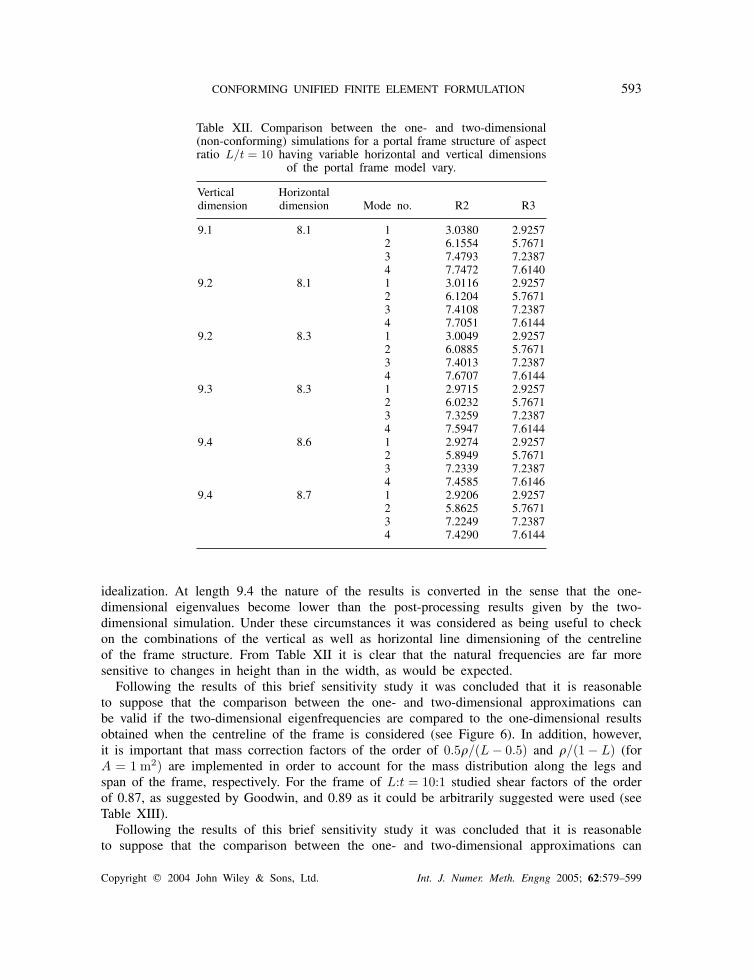
From Table XII it becomes apparent that, as the horizontal dimension is increasing the resultsget less satisfactory. For the horizontal lengths 8.1 and 8.2 the one-dimensional simulationgives higher natural frequencies (as expected) than the two-dimensional idealization of thesystem. However for lengths 8.6 or higher, clearly the one-dimensional Timoshenko idealizationprovides lower results than the Schmidt, Bogner and Fox (R3) simulation. Results of similarform are obtained while the length of both vertical members is increasing from 9.1 to 9.4.For these length values banded in between 9.1 and 9.3 the results are once more sufficientsince the one-dimensional simulation provided lower eigen-frequencies than the two-dimensional
Copyright � 2004 John Wiley & Sons, Ltd. Int. J. Numer. Meth. Engng 2005; 62:579–599
CONFORMING UNIFIED FINITE ELEMENT FORMULATION 593
Table XII. Comparison between the one- and two-dimensional(non-conforming) simulations for a portal frame structure of aspectratio L/t = 10 having variable horizontal and vertical dimensions
of the portal frame model vary.
Vertical Horizontaldimension dimension Mode no. R2 R3
9.1 8.1 1 3.0380 2.92572 6.1554 5.76713 7.4793 7.23874 7.7472 7.6140
9.2 8.1 1 3.0116 2.92572 6.1204 5.76713 7.4108 7.23874 7.7051 7.6144
9.2 8.3 1 3.0049 2.92572 6.0885 5.76713 7.4013 7.23874 7.6707 7.6144
9.3 8.3 1 2.9715 2.92572 6.0232 5.76713 7.3259 7.23874 7.5947 7.6144
9.4 8.6 1 2.9274 2.92572 5.8949 5.76713 7.2339 7.23874 7.4585 7.6146
9.4 8.7 1 2.9206 2.92572 5.8625 5.76713 7.2249 7.23874 7.4290 7.6144
idealization. At length 9.4 the nature of the results is converted in the sense that the one-dimensional eigenvalues become lower than the post-processing results given by the two-dimensional simulation. Under these circumstances it was considered as being useful to checkon the combinations of the vertical as well as horizontal line dimensioning of the centrelineof the frame structure. From Table XII it is clear that the natural frequencies are far moresensitive to changes in height than in the width, as would be expected.
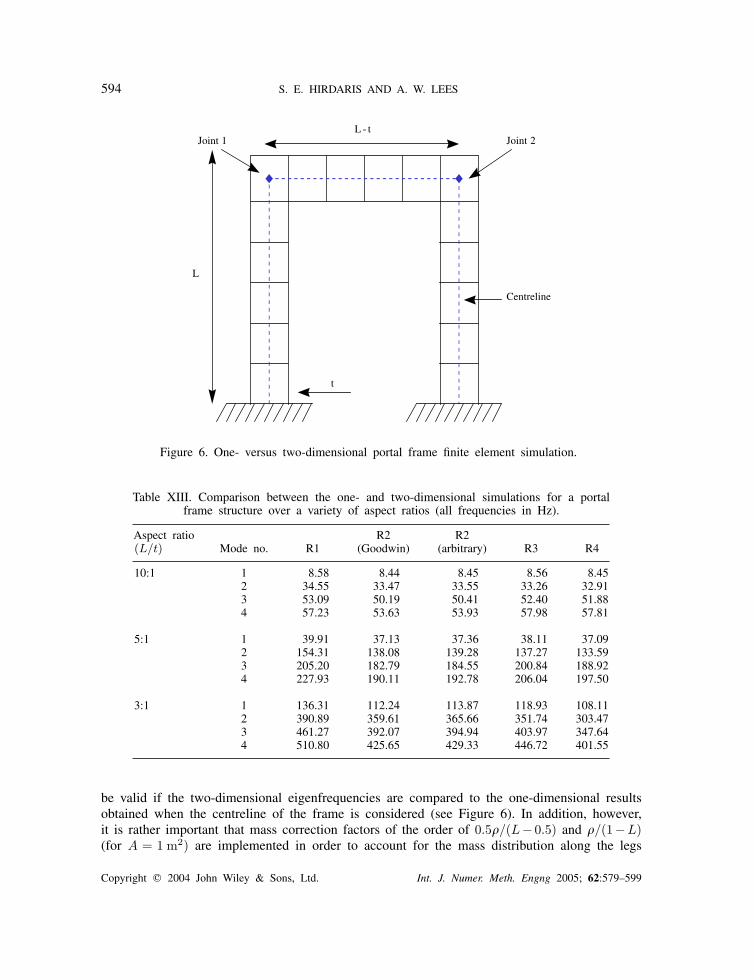
Following the results of this brief sensitivity study it was concluded that it is reasonableto suppose that the comparison between the one- and two-dimensional approximations canbe valid if the two-dimensional eigenfrequencies are compared to the one-dimensional resultsobtained when the centreline of the frame is considered (see Figure 6). In addition, however,it is important that mass correction factors of the order of 0.5�/(L − 0.5) and �/(1 − L) (forA = 1 m2) are implemented in order to account for the mass distribution along the legs andspan of the frame, respectively. For the frame of L:t = 10:1 studied shear factors of the orderof 0.87, as suggested by Goodwin, and 0.89 as it could be arbitrarily suggested were used (seeTable XIII).
Following the results of this brief sensitivity study it was concluded that it is reasonableto suppose that the comparison between the one- and two-dimensional approximations can
Copyright � 2004 John Wiley & Sons, Ltd. Int. J. Numer. Meth. Engng 2005; 62:579–599
594 S. E. HIRDARIS AND A. W. LEES
Joint 2Joint 1
Centreline
L - t
t
L
Figure 6. One- versus two-dimensional portal frame finite element simulation.
Table XIII. Comparison between the one- and two-dimensional simulations for a portalframe structure over a variety of aspect ratios (all frequencies in Hz).
Aspect ratio R2 R2(L/t) Mode no. R1 (Goodwin) (arbitrary) R3 R4
10:1 1 8.58 8.44 8.45 8.56 8.452 34.55 33.47 33.55 33.26 32.913 53.09 50.19 50.41 52.40 51.884 57.23 53.63 53.93 57.98 57.81
5:1 1 39.91 37.13 37.36 38.11 37.092 154.31 138.08 139.28 137.27 133.593 205.20 182.79 184.55 200.84 188.924 227.93 190.11 192.78 206.04 197.50
3:1 1 136.31 112.24 113.87 118.93 108.112 390.89 359.61 365.66 351.74 303.473 461.27 392.07 394.94 403.97 347.644 510.80 425.65 429.33 446.72 401.55
be valid if the two-dimensional eigenfrequencies are compared to the one-dimensional resultsobtained when the centreline of the frame is considered (see Figure 6). In addition, however,it is rather important that mass correction factors of the order of 0.5�/(L− 0.5) and �/(1−L)(for A = 1 m2) are implemented in order to account for the mass distribution along the legs
Copyright � 2004 John Wiley & Sons, Ltd. Int. J. Numer. Meth. Engng 2005; 62:579–599
CONFORMING UNIFIED FINITE ELEMENT FORMULATION 595
and span of the frame, respectively. For the frame of L:t = 10:1 shear factors of the order of0.87, as suggested by Goodwin, and 0.89 as it could be arbitrarily suggested were used (seeTable XIII).
As expected, the effects of rotary inertia and shear deformation become more importantfor lower aspect ratios. From Table XIII it is apparent that the fully conforming planar finiteelement simulation (R4) approximates the frequency of the system at the first mode of vibrationmuch better than the non-conforming (R3) element. This effect becomes more apparent as theframe aspect ratio is decreasing and the effects of shear, particularly at the corners of the framemodel become more significant. An arbitrary increase of the order of 0.02 of the Goodwinshear factor may lead to better results even for slender frame aspect ratios of the order of 10:1.The results of R4 idealization are apparently becoming more beneficial (compared to R3) asthe slenderness frame ratio is becoming of lower order.
DISCUSSION
In this paper, the need has been illustrated for the accurate modelling of important yet fairlysimple structures. In particular, whilst the theory of Timoshenko permits the use of his modifiedbeam theory for low aspect ratios, as these ratios reduce there comes a point where the wholeconcept of beam theory breaks down and resort has to be made to two- or three-dimensionalmodels. This does impose a very high overhead in terms of computation. In particular ithas been shown how a simple portal frame, even with a relatively large aspect ratio requiresmodelling with fully compatible elements, such as that proposed here.
It can be argued that if an adequate understanding of joints were developed, then themajority of a structure such as a portal frame could still be modelled with one-dimensionalelements. In [37] Filipich and Laura analysed the dynamics of a portal frame by consideringthe continuous equation for each component beam them applying the appropriate continuityconstraints. Euler–Bernoulli beam theory was used. A similar analysis could be carried outusing the Timoshenko beam equation, but the authors’ are not aware that such a study hasyet been reported. However, as shown above, this extension has only a fairly narrow range ofapplicability: the real requirement is for a full plane strain analysis of a thick portal frame,or indeed, a full three-dimensional model. This is believed to be an important area of studyas an understanding of the stress field of a full representation may enable the judicious useof smaller models. At the time of writing, it is unclear to the authors whether any analyticsolution for the portal frame is possible but an alternative approach may be to study a largethree dimensional idealization and use the results of this to gain insight into the cross-sectiondistortions at various locations. It is hoped to pursue this type of study in the near future.
CONCLUSIONS
The present work presents a new fully conforming, 32dof, planar finite element formulationthat could be used for the approximation of the natural frequencies of complex free vibratingcontinuous systems comprising of beam models. Special reference has been attributed to theimportance of Timoshenko’s beam theory of vibration which becomes important as the thicknessof the sub-beam components comprising a continuous system is increasing, leading to significantincrease of the effects of rotary inertia and shear deformation.
Copyright � 2004 John Wiley & Sons, Ltd. Int. J. Numer. Meth. Engng 2005; 62:579–599
596 S. E. HIRDARIS AND A. W. LEES
Since the dynamic behaviour of thick beam structures is not adequately described via eitherBernoulli–Euler or Timoshenko theories the planar elements of conforming or non-conformingform have been shown to provide effective means of gaining insight into the problems ofmodelling beam-like structures. It is important, however, to realize that two distinct but relatedmodelling problems arise when using beam elements. First, because only transverse displacementand slope are normally continuous at a node, shear force and bending moment distributionsmay become distorted. This may be overcome by use of higher-order beam elements but thepenalty is some difficulty in placing such elements within a global representation. The secondproblem is more difficult and concerns the cross-section displacement profile at the change ofsection. This may only be resolved by the use of either two- or three-dimensional element sincethe basic hypothesis of beam theory is challenged. Special care is needed in choosing the mostappropriate shear factor in beam model representations. It has been shown that two-dimensionaleffects can become important in the analysis of structures with non-uniform beams.
Along these lines, the new fully conforming, two-dimensional 32dof finite element wasshown to be particularly advantageous for the case of a portal frame structure where thickbeam structures join at right angles although at higher discretization levels the formulationcould become slightly ‘uneconomic’. Inevitably, the use of in-plane elements involves a highernumber of degrees of freedom. In the two studies with the stepped beams, the plate modelsperformed in satisfactory manner, showing in some cases substantial difference from beamtype behaviour. In specific for the case of a portal frame appears that the use of a the newfully conforming finite element idealization is rather important. This is perhaps to be expectedsince shear effects will have very strong influence at the corners and it is not surprising thatit is important to reflect that by using a fully conforming element. An eigenvalue reductiontechnique could be used in order to make the element more economic. However, this technique[44] that reduces freedoms out on static basis by using certain master freedoms, will haveraised the frequencies slightly from their value for the model taken.
Since most problems of such nature are degree of freedom limited future work will beconcentrated in comparing the present finite element model with alternative two-dimensionalplate elements having the same total number of degrees of freedom. The fact that most non-academic finite element practitioners may prefer, at the moment, to resolve such problems bymeans of three-dimensional solid finite element idealizations is also acknowledged. Along theselines comparison of the new conforming idealization over the commercial three-dimensionalsolid models will be performed especially for the cases of lower aspect ratio. An experimentalverification of the model will also be carried out so that the finite element model can bevalidated and appropriately updated.
APPENDIX A
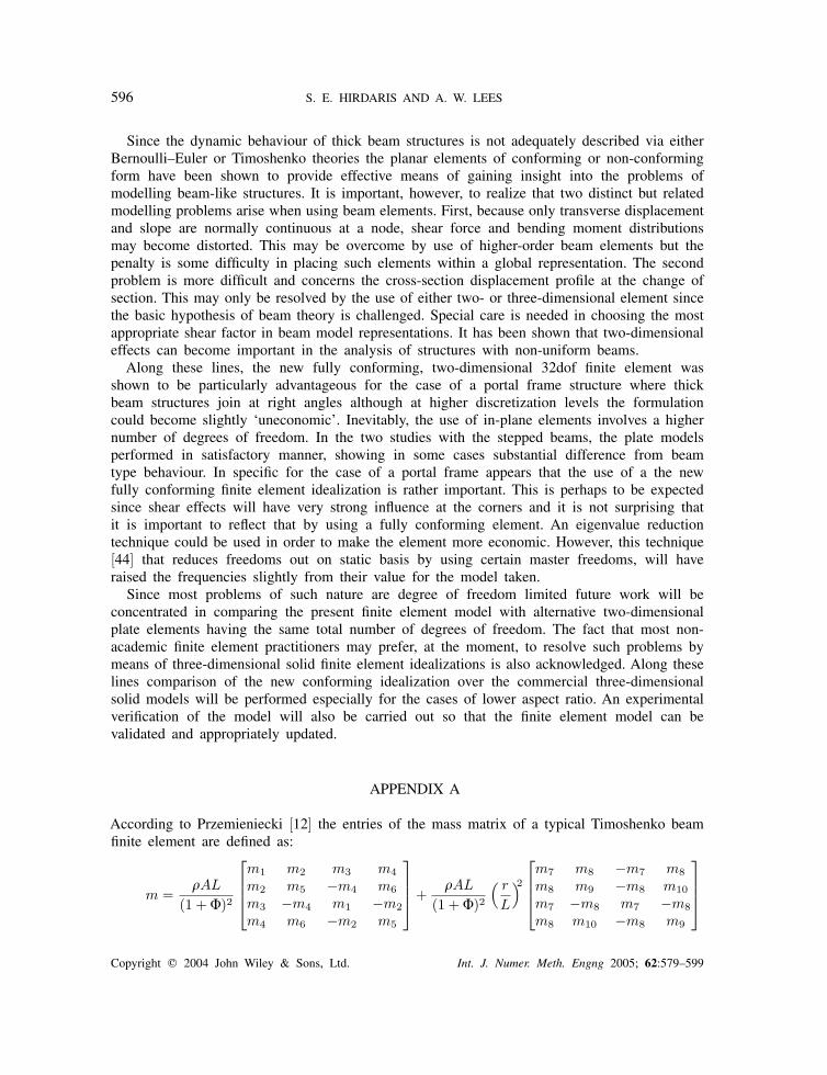
According to Przemieniecki [12] the entries of the mass matrix of a typical Timoshenko beamfinite element are defined as:
m =�AL
(1 + �)2
m1 m2 m3 m4m2 m5 −m4 m6m3 −m4 m1 −m2m4 m6 −m2 m5
+
�AL
(1 + �)2( r
L
)2
m7 m8 −m7 m8m8 m9 −m8 m10m7 −m8 m7 −m8m8 m10 −m8 m9
Copyright � 2004 John Wiley & Sons, Ltd. Int. J. Numer. Meth. Engng 2005; 62:579–599
CONFORMING UNIFIED FINITE ELEMENT FORMULATION 597
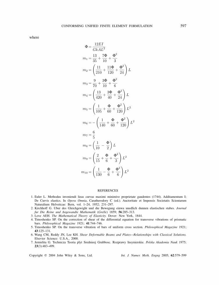
where
� =12EI
GkAL2
m1 =1335
+7�10
+�2
3
m2 =
(11210
+11�120
+�2
24
)L
m3 =970
+3�10
+�2
6
m4 =
(13420
+3�40
+�2
24
)L
m5 =
(1
105+
�60
+�2
120
)L2
m6 = −(
1140
+�60
+�2
120
)L2
m7 =65
m8 =(
110
− �2
)L
m9 =
(215
+�6
+�2
3
)L2
m10 =
(1
130− �
6+
�2
6
)L2
REFERENCES
1. Euler L. Methodus inveniendi lieas curvas maximi minimive proprietate gaudentes (1744). Additamentum I;De Curvis elastics. In Opera Omnia, Caratherodory C (ed.). Auctoritate et Impensis Societatis ScientarumNaturalium Helveticae: Bern, vol. 1–24, 1952; 231–297.
2. Kirchhoff G. Uber des Gleichgewight und die Bewegung einwa unedlich dunnen elastischen stabes. Journalfur Die Reine und Angewandte Mathematik (Grelle) 1859; 56:285–313.
3. Love AEH. The Mathematical Theory of Elasticity. Dover: New York, 1844.4. Timoshenko SP. On the correction of shear of the differential equation for transverse vibrations of prismatic
bars. Philosophical Magazine 1921; 41:744–746.5. Timoshenko SP. On the transverse vibration of bars of uniform cross section. Philosophical Magazine 1921;
43:125–131.6. Wang CM, Reddy JN, Lee KH. Shear Deformable Beams and Plates—Relationships with Classical Solutions.
Elsevier Science: U.S.A., 2000.7. Jemielita G. Technicza Teoria plyt Srednieej Grubbosc. Rozprawy Insynierskie. Polska Akademia Nauk 1975;
23(3):483–499.
Copyright � 2004 John Wiley & Sons, Ltd. Int. J. Numer. Meth. Engng 2005; 62:579–599
598 S. E. HIRDARIS AND A. W. LEES
8. Levinson M. A new rectangular beam theory. Journal of Sound and Vibration 1981; 74:81–87.9. Bickford WB. A consistent higher order beam theory. Developments of Theoretical and Applied Mechanics
1982; 11:137–150.10. Reddy JN. A simple higher order theory for laminated composite plates. Journal of Applied Mechanics
1984; 51:745–752.11. Reddy JN. Energy and Variational Methods in Applied Mechanics. Wiley: New York, 1984.12. Przemieniecki JS. Theory of Matrix Structural Analysis (2nd edn). McGraw-Hill: New York, 1970.13. Dawe DJ. Matrix and Finite Element Displacement Analysis of Structures (1st edn). Oxford Engineering
Science Series: U.K., 1988.14. Clough RW, Penzien J. Dynamics of Structures. McGraw-Hill: New York, 1975.15. Thomas DL, Wilson JM, Wilson RR. Timoshenko beam finite elements. Journal of Sound and Vibration
1973; 31(3):315–330.16. Thomas DL, Abbas BA. Finite element model for the dynamic analysis of Timoshenko beams. Journal of
Sound and Vibration 1975; 41:291–299.17. Lees AW, Thomas DL. A unified Timoshenko beam finite element. Journal of Sound and Vibration 1982;
80:355–366.18. Heyliger PR, Reddy JN. A higher order beam finite element for bending and vibration problems. Journal
of Sound and Vibration 1988; 126(2):309–326.19. Hirdaris SE. Finite element modelling of free vibrating continuous systems. MSc (Eng.) Dissertation,
University of Wales Swansea, UK, 1998.20. Lees AW, Hirdaris SE. Models for thick beams and frames. 17th International Modal Analysis Conference
(IMAC), Kissimmee, FL, U.S.A., 1999; 1:1531–1537.21. Hirdaris SE, Lees AW. On the identification of natural frequencies of thick portal frames. 7th International
Conference on Recent Advances in Structural Dynamics 2002. Finite elements and applications, vol. 2.Institute of Sound and Vibration Research (ISVR), Southampton, U.K., 2002, 887–899.
22. Rao SS. Mechanical Vibrations (3rd edn). Addison-Wesley: U.K., 1992.23. Hirdaris SE. Hydroelastic modelling for the prediction of wave induced loads on bulk carriers. Ph.D. Thesis,
University of Southampton, U.K., 2002.24. Gupta RS, Rao SS. Finite element eigenvalue analysis of tapered and twisted beam systems. Journal of
Sound and Vibration 1971; 14(2):215–227.25. Sanderson N, Kitching R. Flexibility of shafts with abrupt changes of section. International Journal of
Mechanical Sciences 1978; 20:189–199.26. Balasubramanian TS, Subramanian G. Beneficial effects of steps on the free vibration characteristics of
beams. Journal of Sound and Vibration 1987; 118(3):555–560.27. Gupta AP, Sharma N. Effect of shear and rotary inertia on the forced motion of a stepped rectangular
beam. Journal of Sound and Vibration 1998; 209(5):811–820.28. Filipich CP, Laura PAA, Sonenblum M, Gill E. Transverse vibrations of a stepped beam subject to an
axial force embedded in a non-homogeneous Winkler foundation. Journal of Sound and Vibration 1988;126(1):1–8.
29. Bepat CN, Bhutani N. General approach for free and forced vibration of stepped systems governed bythe one dimensional wave equation with non-classical boundary conditions. Journal of Sound and Vibration1994; 172(1):1–22.
30. Gupta AP, Sharma N. Forced motion of a stepped semi-infinite plate. Journal of Sound and Vibration 1997;203:697–705.
31. Jang SK, Bert CW. Free vibration of a stepped beam: exact and numerical solutions. Journal of Sound andVibration 1989; 130(2):342–346.
32. Oguamanam DCD, Hansen JS, Heppler GR. Vibration of arbitrarily oriented two member open frames withtip mass. Journal of Sound and Vibration 1998; 107:652–669.
33. Rieger NF, McCallion H. The natural frequencies of portal frames—I. International Journal of MechanicalSciences 1965; 7:253–261.
34. Rieger NF, McCallion H. The natural frequencies of portal frames—II. International Journal of MechanicalSciences 1965; 7:253–261.
35. Filipich CP, Valegra de Greco BH, Laura PAA. A note on the analysis of symmetric mode of vibrations ofportal frames. Journal of Sound and Vibration 1987; 117:198–201.
36. Laura PAA, Valerga de Greco BH. In plane vibrations of frames carrying concentrated masses. Journal ofSound and Vibration 1987; 117:447–458.
Copyright � 2004 John Wiley & Sons, Ltd. Int. J. Numer. Meth. Engng 2005; 62:579–599
CONFORMING UNIFIED FINITE ELEMENT FORMULATION 599
37. Filipich CP, Laura PAA. In plane vibrations of portal frames with end supports elastically restrained againstrotation and translation. Journal of Sound and Vibration 1987; 117:467–474.
38. Chang CH, Wang PY, Lin YW. Vibration of X-braced portal frames. Journal of Sound and Vibration 1987;117:233–248.
39. Mottershead JE, Tee TK, Foster CD. An experiment to identify the structural dynamics of a portal frame.Journal of Vibration and Acoustics 1990; 112:78–83.
40. Lee HP, Ng TY. In plane vibration of planar frame structures. Journal of Sound and Vibration 1994;172:420–427.
41. Alexandropoulos A, Michaliatsos G, Koundis K. The effect of longitudinal motion and other parameters onthe bending eigenfrequencies of a simple frame. Journal of Sound and Vibration 1986; 106:153–159.
42. Hughes R. Ship Structural Design an Optimised Rationally Based Approach. The Society of Naval Architectsand Marine Engineers, SNAME Publications: New York, 1992.
43. Cowper GR. The shear coefficient in Timoshenko’s beam theory. Journal of Applied Mechanics (ASME)1966; 33:335–339.
44. Bathe KJ. Finite Element Procedures (3rd edn). Prentice-Hall Inc.: U.S.A., 1996.
Copyright � 2004 John Wiley & Sons, Ltd. Int. J. Numer. Meth. Engng 2005; 62:579–599
Related Documents