HAL Id: hal-02651095 https://hal-univ-rennes1.archives-ouvertes.fr/hal-02651095 Submitted on 12 Jun 2020 HAL is a multi-disciplinary open access archive for the deposit and dissemination of sci- entific research documents, whether they are pub- lished or not. The documents may come from teaching and research institutions in France or abroad, or from public or private research centers. L’archive ouverte pluridisciplinaire HAL, est destinée au dépôt et à la diffusion de documents scientifiques de niveau recherche, publiés ou non, émanant des établissements d’enseignement et de recherche français ou étrangers, des laboratoires publics ou privés. A Conformal Ultrawideband Antenna with Monopole-Like Radiation Patterns Bahare Mohamadzade, Roy B. V. B. Simorangkir, Raheel M. Hashmi, Ali Lalbakhsh To cite this version: Bahare Mohamadzade, Roy B. V. B. Simorangkir, Raheel M. Hashmi, Ali Lalbakhsh. A Confor- mal Ultrawideband Antenna with Monopole-Like Radiation Patterns. IEEE Transactions on Anten- nas and Propagation, Institute of Electrical and Electronics Engineers, 2020, 68 (8), pp.6383-6388. 10.1109/TAP.2020.2969744. hal-02651095

Welcome message from author
This document is posted to help you gain knowledge. Please leave a comment to let me know what you think about it! Share it to your friends and learn new things together.
Transcript
HAL Id: hal-02651095https://hal-univ-rennes1.archives-ouvertes.fr/hal-02651095
Submitted on 12 Jun 2020
HAL is a multi-disciplinary open accessarchive for the deposit and dissemination of sci-entific research documents, whether they are pub-lished or not. The documents may come fromteaching and research institutions in France orabroad, or from public or private research centers.
L’archive ouverte pluridisciplinaire HAL, estdestinée au dépôt et à la diffusion de documentsscientifiques de niveau recherche, publiés ou non,émanant des établissements d’enseignement et derecherche français ou étrangers, des laboratoirespublics ou privés.
A Conformal Ultrawideband Antenna withMonopole-Like Radiation Patterns
Bahare Mohamadzade, Roy B. V. B. Simorangkir, Raheel M. Hashmi, AliLalbakhsh
To cite this version:Bahare Mohamadzade, Roy B. V. B. Simorangkir, Raheel M. Hashmi, Ali Lalbakhsh. A Confor-mal Ultrawideband Antenna with Monopole-Like Radiation Patterns. IEEE Transactions on Anten-nas and Propagation, Institute of Electrical and Electronics Engineers, 2020, 68 (8), pp.6383-6388.�10.1109/TAP.2020.2969744�. �hal-02651095�
ACCEPTED MANUSCRIPT
This article has been accepted for publication in a future issue of this journal, but has not been fully edited. Content may change prior to final publication. Citation information: DOI 10.1109/TAP.2020.2969744, IEEETransactions on Antennas and Propagation
1
CommunicationA Conformal Ultrawideband Antenna with Monopole-Like Radiation Patterns
Bahare Mohamadzade, Roy B. V. B. Simorangkir, Raheel M. Hashmi, and Ali Lalbakhsh
Abstract—A simple conformal ultrawideband (UWB) antennawith monopole-like radiation patterns is proposed in this commu-nication. To achieve the wide bandwidth, two rings are arrangedconcentrically around the main annular-ring circular patchantenna, in which two rectangular slots are added. The antennahas monopole-like radiation patterns generated by combiningfour propagation modes of TM01, TM02, TM03, and TM04
throughout the operating bands. To enhance the flexibility androbustness, the proposed antenna is fabricated using conductivefabric embedded into polydimethylsiloxane (PDMS) polymer. Toour knowledge, this is the first flexible UWB antenna withmonopole-like radiation patterns reported in the open literature.The measured results show that the antenna achieves a 10 dBreturn loss bandwidth from 2.85 to 8.6 GHz. Monopole-like ra-diation patterns are maintained throughout the frequency band,agreeing well with simulated results. This has been validatedthrough the measured Mean Realized Gain (MRG) pattern from2.85 to 8.6 GHz. The fabricated antenna was bent and testedat various curvatures to verify its conformability. To evaluatesuitability for UWB communications, the system-fidelity factorsof the antenna are investigated using full-wave analysis in CSTMicrowave Studio, in both flat and bent conditions, validatingits potential for UWB pulse transmission.
Index Terms—Circular patch, conformal antenna, flexible an-tenna, monopole-like radiation pattern, ring patch, ultrawide-band (UWB).
I. INTRODUCTION
The extensive demands in broadband wireless communi-cation have brought attentions to the ultrawideband (UWB)technology. This is owing to its versatile features of high data-rate transmission a over short distance, low power consump-tion, and robustness against multipath [1]. Current researchefforts in this area include the development of compact UWBantennas having monopole-like radiation characteristics. Suchantennas are of interest in applications that require verticalpolarized waves for minimum path-loss and omnidirectionalradiation characteristics for wide coverage in all directions. Ontop of that, due to the space limitations and the nature of theapplications, having antennas that are physically small or lowvisual signature is generally of paramount importance. Amongthem are Wireless Body Area Networks (WBANs), unmannedaerial vehicles (UAVs), synthetic aperture radar (SAR), self-managing ground sensor networks, in-vehicle sensing andnetwork surveillance [2]–[8].
This work was supported in part by the International Macquarie UniversityResearch Excellence Scholarship (iMQRES).
B. Mohamadzade, R. M. Hashmi, and A. Lalbakhsh are with the Schoolof Engineering, Macquarie University, Sydney, NSW 2109, Australia (email:[email protected]).
R. B. V. B. Simorangkir is with the University of Rennes 1, CNRS, Institutd’Electronique et de Telecommunications of Rennes (IETR)-UMR 6164, F-35000 Rennes, France and the School of Engineering, Macquarie University,Sydney, NSW 2109, Australia (e-mail: [email protected]).
Modified vertically-polarized electric monopole antennasover a ground plane are perhaps the most basic ways to achievean UWB antenna with radiation characteristics mentionedabove. Variations on this class of antenna have been reportedin the past for achieving a considerably large bandwidth thanthe conventional designs, including the shape modificationsof the cylindrical stub radiator [9], [10], the substitution ofthe cylindrical stub with planar plates with various shapes[11], [12], or the dielectric loading on monopole radiator [13].Though the design goals have been achieved, the drawbackof these approaches is that the high profile and the rigidstructure associated with such antennas may not be suitablefor applications requiring low profile and conformability, suchas those mounted over the exterior of a vehicle or a person’sbody. A number of significant efforts have been thereforeconducted to realize compact and low-profile UWB antennaswith monopole-like radiation characteristics, utilizing variousradiating elements from loops, bow tie, to monocones, with orwithout top-hat loadings [4], [7], [8], [14]–[18].
An UWB antenna based on magnetically-coupled two sec-toral loop structures with dimension of 1.36λmin×1.36λmin
is developed in [14]. It presents a slightly compact structurewith height of 0.16λmin yet, the height was still relativelyhigher for ambient applications. The same issue also can beseen in the 3-D loops design in [17] in addition to the twofeeding points which add design complexity to this presentedstructure. Miniaturized version of [14] having a lower height of0.053λmin was later reported in [4]. This noticeably reducedheight of the antenna was unfortunately compromised by alarger lateral area (0.9λmin×0.9λmin).
Another design with a very compact dimension of0.26λmin×0.26λmin×0.046λmin, (fmin = 0.66 GHz) waspresented in [16]. The design was developed from thethe compact two bent-diamond structure with dimension of0.22λmin×0.22λmin×0.033λmin in [7], providing an im-proved consistency of the radiation patterns. The antennarequires a frequency-dependent feeding network with the helpof a diplexer and a power divider, which unfortunately presentsnew challenges in terms of cost, weight and complexity in thestructure.
Different approach utilizing various conical structures havebeen proposed in [8], [15], [18]. In [8], a low profile of0.086λmin achieved by the introduction of a small cylinderin the antenna configuration, which was then covered by aradome to protect the delicate pins. In [15], four thin shortingpins with diameter of 1 mm are used to short the patch on thetop of monocone structure to the ground in order to generateadditional resonance with the higher-order TM41 mode. In[18], directors, nylon spacers and four loops were added
ACCEPTED MANUSCRIPT
This article has been accepted for publication in a future issue of this journal, but has not been fully edited. Content may change prior to final publication. Citation information: DOI 10.1109/TAP.2020.2969744, IEEETransactions on Antennas and Propagation
2
to the monocone, providing improvement in performance,and concurrently adding the complexity, thus necessitatinga rigid structure with protection to delicate parts for someapplications. Despite the success, all the aforementioned UWBantennas were composed of 3-D shaped structure and made ofrigid materials. These characteristics present a challenge fortheir use in several modern wireless applications where theplatforms are curved, and require a conformal antenna thatis resilient to the surroundings and mechanically robust, forinstance, automobile exteriors in vehicular networks, leadingedge of an aircraft wing, and human body in WBANs [19]–[21].
In this paper, a conformal UWB antenna with monopole-like radiation patterns is presented. The antenna presents aplanar and flexible structure, making it suitable for conformalapplications and is compact both laterally as well as in termsof height. The proposed antenna was fabricated based on thePDMS-conductive fabric composite technique, in which all an-tenna parts, including radiator and ground plane are embeddedinside the PDMS, making it resilient to harsh environment,and hence suitable for the applications outlined above. Theradiating structure comprises of an annular-ring circular patchloaded with two rectangular slots, and two additional parasiticrings added concentrically around the annular-ring circularpatch.
The presented flexible antenna is based on circular patchantenna which does not require any extra matching circuitryand offers a wide impedance bandwidth, ranging from 2.85 to8.6 GHz. By combining multiple TM0n modes, the antennabandwidth has improved considerably compared to the otherreported monopolar patch antennas, e.g., wideband circu-lar patch antenna with two coupled annular rings (5.45 to7.16 GHz, 27.1%) [22], circular microstrip patch antenna witha coupled annular ring (12.8% at the 5.8 GHz) [23], andcircular ring patch shorted to the ground plane by four shortingposts and a coupling patch connected with a feeding (4.27to 8.72 GHz, 68.5%) [24], whereas the structure is flexiblewithout using any rigid pins.
The design and fabrication guidelines of the antenna aregiven. The characteristics of the antenna are investigatedthrough simulations and measurements both when the antennais in flat condition and when it is conformed over variouscylindrical surface, validating its conformability. The capa-bility for UWB pulse transmission is also evaluated throughSystem Fidelity Factor (SFF) investigations.
II. PROPOSED UWB ANTENNA
A. Antenna Configuration and Design Method
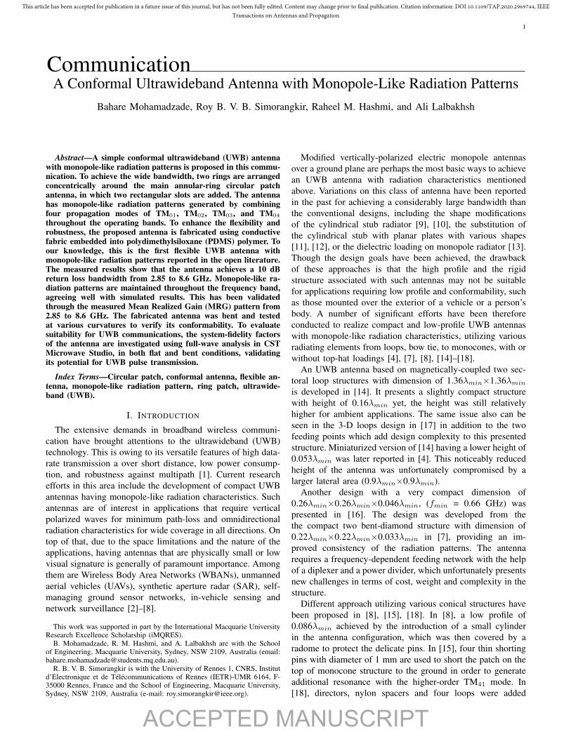
The configuration of the proposed antenna is depicted inFig. 1. The design comprises an annular-ring circular patchantenna, concentrically loaded with other two ring patches.The radiator layers, having a total radius of r6, are printed ontop of a hs thickness polydimethylsiloxane (PDMS) substrate.The permittivity of the PDMS is relatively constant at 2.77with an increasing loss tangent from 0.02 to 0.076 from 2 to10 GHz based on the measurement conducted using Agilent85070E Dielectric Probe Kit. Underneath the radiator patches,there is a full ground plane layer with a radius of Rg . PDMS
PDMS
Cond.fabric
(a) (b)
Groundplane
SMARadiator
Ring 2
Ring 1
Ring 3
r6
r5 r4
r2
Rg
r3
ds
l
w
xy
zy
d
r1
ht hbhs
Fig. 1. Proposed antenna geometry: (a) front view, (b) side view. The finaldimensions are r1 = 1.5, r2 = 22, r3 = 23, r4 = 31, r5 = 34, r6 = 37,Rg = 38, l = 11, w = 3, ds = 4, d = 0.5, ht = 0.2, hs = 5.5, and hb = 0.2.All dimensions are in millimeters.
Step 1Step 2Step 3Step 4Step 5
|S1
1| (
dB
)
-30
-10
-20
0
-40
Frequency (GHz)3 4 5 6 7 8 9 102
Fig. 2. Simulated |S11| of the antenna for each design step.
encapsulation layers which completely cover the antenna, wereadded to provide mechanical robustness and resilience to thestructure [21], [25].
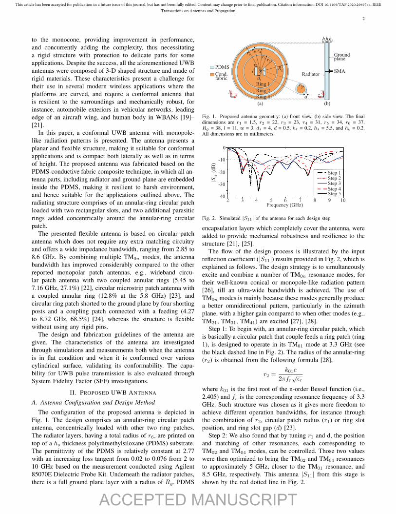
The flow of the design process is illustrated by the inputreflection coefficient (|S11|) results provided in Fig. 2, which isexplained as follows. The design strategy is to simultaneouslyexcite and combine a number of TM0n resonance modes, fortheir well-known conical or monopole-like radiation pattern[26], till an ultra-wide bandwidth is achieved. The use ofTM0n modes is mainly because these modes generally producea better omnidirectional pattern, particularly in the azimuthplane, with a higher gain compared to when other modes (e.g.,TM21, TM31, TM41) are excited [27], [28].
Step 1: To begin with, an annular-ring circular patch, whichis basically a circular patch that couple feeds a ring patch (ring1), is designed to operate in its TM01 mode at 3.3 GHz (seethe black dashed line in Fig. 2). The radius of the annular-ring(r2) is obtained from the following formula [28],
r2 =k01c
2πfr√εr
where k01 is the first root of the n-order Bessel function (i.e.,2.405) and fr is the corresponding resonance frequency of 3.3GHz. Such structure was chosen as it gives more freedom toachieve different operation bandwidths, for instance throughthe combination of r2, circular patch radius (r1) or ring slotposition, and ring slot gap (d) [23].
Step 2: We also found that by tuning r1 and d, the positionand matching of other resonances, each corresponding toTM02 and TM04 modes, can be controlled. Those two valueswere then optimized to bring the TM02 and TM04 resonancesto approximately 5 GHz, closer to the TM01 resonance, and8.5 GHz, respectively. This antenna |S11| from this stage isshown by the red dotted line in Fig. 2.
ACCEPTED MANUSCRIPT
This article has been accepted for publication in a future issue of this journal, but has not been fully edited. Content may change prior to final publication. Citation information: DOI 10.1109/TAP.2020.2969744, IEEETransactions on Antennas and Propagation
3
|S1
1| (
dB
)
-40
-10
-20
-30
0
-50
-60
Frequency (GHz)3 4 5 6 7 8 9 102
hs = 5.1 mmhs = 6.1 mmhs = 7.1 mmhs = 8.1 mmhs = 9.1 mm
Fig. 3. Simulated |S11| of the antenna for different substrate thickness (hs).
(a) (c) (d)(b)
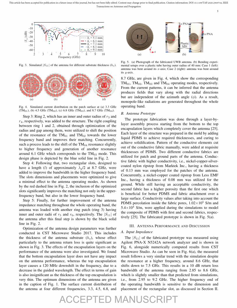
Fig. 4. Simulated current distribution on the patch surface at (a) 3.3 GHz(TM01), (b) 4.5 GHz (TM02), (c) 6.8 GHz (TM03), and 8.7 GHz (TM04).
Step 3: Ring 2, which has an inner and outer radius of r3 andr4, respectively, was added to the structure. The right couplingbetween ring 1 and 2, obtained through optimization of theradius and gap among them, were utilized to shift the positionof the resonance of the TM01 and TM02 towards the lowerfrequency band and improves their matching. Concurrently,such a process leads to the shift of the TM04 resonance slightlyto higher frequency and generation of another resonancearound 6.1 GHz which corresponds to the TM03 mode. Thisdesign phase is depicted by the blue solid line in Fig. 2.
Step 4: Following that, two rectangular slots, designed tohave a length (l) of approximately λg/2 at 8.7 GHz, wereadded to improve the bandwidth in the higher frequency band.The slots dimensions and placements were optimized to givea minimal effect to the antenna operating modes. As shownby the red dashed line in Fig. 2, the inclusion of the optimizedslots significantly improves the matching not only in the upper-frequency band, but also in the lower frequency band.
Step 5: Finally, for further improvement of the antennaimpedance matching throughout the whole operating band, theantenna was loaded with another ring patch (ring 3) havinginner and outer radii of r5 and r6, respectively. The |S11| ofthe antenna after this final step is shown by the black solidline in Fig. 2.
Optimization of the antenna design parameters was furtherconducted in CST Microwave Studio 2017. This includesthe thickness of the antenna substrate (hs), whose effectparticularly to the antenna return loss is quite significant asshown in Fig. 3. The effects of the encapsulation layers on theperformance of the antenna were also investigated. We foundthat the bottom encapsulation layer does not have any impacton the antenna performance, whereas the top encapsulationlayer causes a 120 MHz downshift in the frequency, due to adecrease in the guided wavelength. The effect in terms of gainis also insignificant as the thickness of the top encapsulation isvery thin. The optimum dimensions of the antenna are givenin the caption of Fig. 1. The surface current distribution ofthe antenna at four different frequencies, 3.3, 4.5, 6.8, and
x
y
(a)
To PNA
Plastictube
To PNA
(b)
Fig. 5. (a) Photograph of the fabricated UWB antenna. (b) Bending experi-mental setups over a plastic tube having outer radius of 40 mm: Case 1 (left):antenna was bent around its x-axis; Case 2 (right): antenna was bent aroundits y-axis.
8.7 GHz, are given in Fig. 4, which show the correspondingTM01, TM02, TM03 and TM04 operating modes, respectively.From the current patterns, it can be inferred that the antennaproduces fields that vary along with the radial directionsbut are independent of the azimuth angle (φ). As a result,monopole-like radiations are generated throughout the wholeoperating band.
B. Antenna Prototype
The prototype fabrication was done through a layer-by-layer assembly process starting from the bottom to the topencapsulation layers which completely cover the antenna [25].Each layer of the structure was prepared in the mold by addingliquid PDMS to achieve required thicknesses, and curing toachieve solidification. Pattern of the conductive elements cutout of the conductive fabric manually, were added at requisitethicknesses of PDMS. Two different conductive fabrics areutilized for patch and ground parts of the antenna. Conduc-tive fabric with higher conductivity, i.e., nickel-copper-silver-coated nylon ripstop from Marktek Inc., having a thicknessof 0.13 mm was employed for the patches of the antenna.Concurrently, a nickel-copper coated ripstop from Less EMFInc., having a thickness of 0.08 mm was utilized for theground. While still having an acceptable conductivity, thesecond fabric has a higher porosity than the first one whichis beneficial for better PDMS and fabric attachment over alarge surface. Conductivity values after taking into account thePDMS percolation inside the fabric pores, 1.02×10⁵ S/m and5.4×104 S/m, were applied during the simulations to modelthe composite of PDMS with first and second fabrics, respec-tively [25]. The fabricated prototype is shown in Fig. 5(a).
III. ANTENNA PERFORMANCE AND DISCUSSION
A. Input Impedance
The |S11| of the fabricated prototype was measured usingAgilent PNA-X N5242A network analyzer and is shown inFig. 6, alongside numerically computed results from CSTMicrowave Studio. As can be seen in Fig. 6(a), the measuredresult follows a very similar trend with the simulation despitethe resonance at a higher frequency, around 8.6 GHz, thatshifts down to 7.5 GHz. This results in a 10 dB return lossbandwidth of the antenna ranging from 2.85 to 8.6 GHz,which is slightly smaller than that predicted from simulations,i.e., from 2.95 to 9.2 GHz. The higher frequency end ofthe operating bandwidth is sensitive to the dimension andplacement of the rectangular slot, as discussed in Section II.
ACCEPTED MANUSCRIPT
This article has been accepted for publication in a future issue of this journal, but has not been fully edited. Content may change prior to final publication. Citation information: DOI 10.1109/TAP.2020.2969744, IEEETransactions on Antennas and Propagation
4
|S1
1| (
dB
)
-30
-10
-20
0
-40
Frequency (GHz)3 4 5 6 7 8 9 102
Frequency (GHz)3 4 5 6 7 8 9 102
-50
-60
|S1
1| (
dB
)
-30
-10
-20
0
-40
-50
Sim.Meas.
(a)
(b)
Sim. x-axisMeas. x-axisSim. y-axisMeas. y-axis
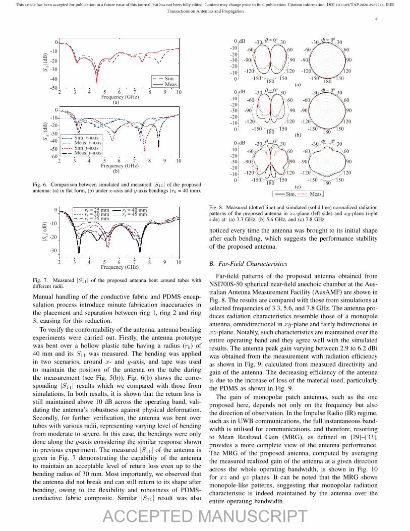
Fig. 6. Comparison between simulated and measured |S11| of the proposedantenna: (a) in flat form, (b) under x-axis and y-axis bendings (rb = 40 mm).
|S1
1| (
dB
)
-20
-10
0
-30
Frequency (GHz)3 4 5 6 7 8 9 102
rb = 25 mmrb = 30 mmrb = 35 mm
rb = 40 mmrb = 45 mm
Fig. 7. Measured |S11| of the proposed antenna bent around tubes withdifferent radii.
Manual handling of the conductive fabric and PDMS encap-sulation process introduce minute fabrication inaccuracies inthe placement and separation between ring 1, ring 2 and ring3, causing for this reduction.
To verify the conformability of the antenna, antenna bendingexperiments were carried out. Firstly, the antenna prototypewas bent over a hollow plastic tube having a radius (rb) of40 mm and its S11 was measured. The bending was appliedin two scenarios, around x- and y-axis, and tape was usedto maintain the position of the antenna on the tube duringthe measurement (see Fig. 5(b)). Fig. 6(b) shows the corre-sponding |S11| results which we compared with those fromsimulations. In both results, it is shown that the return loss isstill maintained above 10 dB across the operating band, vali-dating the antenna’s robustness against physical deformation.Secondly, for further verification, the antenna was bent overtubes with various radii, representing varying level of bendingfrom moderate to severe. In this case, the bendings were onlydone along the y-axis considering the similar response shownin previous experiment. The measured |S11| of the antenna isgiven in Fig. 7 demonstrating the capability of the antennato maintain an acceptable level of return loss even up to thebending radius of 30 mm. Most importantly, we observed thatthe antenna did not break and can still return to its shape afterbending, owing to the flexibility and robustness of PDMS-conductive fabric composite. Similar |S11| result was also
Φ = 00
(a)
30
60
90
120
150180
-150
-120
-90
-60
-30 θ = 00
-30-20
-20
0
0
dB
-10
-10
30
60
90
120
150180
-150
-120
-90
-60
-30
Φ = 00
(b)
30
60
90
120
150180
-150
-120
-90
-60
-30 θ = 00
-30-20
-20
0
0
dB
-10
-10
30
60
90
120
150180
-150
-120
-90
-60
-30
Φ = 00
(c)
30
60
90
120
150180
-150
-120
-90
-60
-30 θ = 00
-30-20
-20
0
0
dB
-10
-10
30
60
90
120
150180
-150
-120
-90
-60
-30
Sim. Meas.
Fig. 8. Measured (dotted line) and simulated (solid line) normalized radiationpatterns of the proposed antenna in xz-plane (left side) and xy-plane (rightside) at: (a) 3.3 GHz, (b) 5.6 GHz, and (c) 7.8 GHz.
noticed every time the antenna was brought to its initial shapeafter each bending, which suggests the performance stabilityof the proposed antenna.
B. Far-Field Characteristics
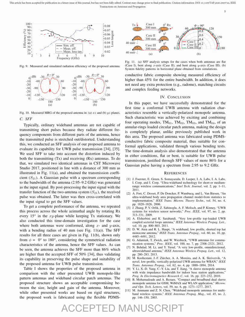
Far-field patterns of the proposed antenna obtained fromNSI700S-50 spherical near-field anechoic chamber at the Aus-tralian Antenna Measurement Facility (AusAMF) are shown inFig. 8. The results are compared with those from simulations atselected frequencies of 3.3, 5.6, and 7.8 GHz. The antenna pro-duces radiation characteristics resemble those of a monopoleantenna, omnidirectional in xy-plane and fairly bidirectional inxz-plane. Notably, such characteristics are maintained over theentire operating band and they agree well with the simulatedresults. The antenna peak gain varying between 2.9 to 6.2 dBiwas obtained from the measurement with radiation efficiencyas shown in Fig. 9, calculated from measured directivity andgain of the antenna. The decreasing efficiency of the antennais due to the increase of loss of the material used, particularlythe PDMS as shown in Fig. 9.
The gain of monopolar patch antennas, such as the oneproposed here, depends not only on the frequency but alsothe direction of observation. In the Impulse Radio (IR) regime,such as in UWB communications, the full instantaneous band-width is utilised for communications, and therefore, resortingto Mean Realized Gain (MRG), as defined in [29]–[33],provides a more complete view of the antenna performance.The MRG of the proposed antenna, computed by averagingthe measured realized gain of the antenna at a given directionacross the whole operating bandwidth, is shown in Fig. 10for xz and yz planes. It can be noted that the MRG showsmonopole-like patterns, suggesting that monopolar radiationcharacteristic is indeed maintained by the antenna over theentire operating bandwidth.
ACCEPTED MANUSCRIPT
This article has been accepted for publication in a future issue of this journal, but has not been fully edited. Content may change prior to final publication. Citation information: DOI 10.1109/TAP.2020.2969744, IEEETransactions on Antennas and Propagation
5
Frequency (GHz)3 4 5 6 7 8 9 102
Eff
icie
ncy
(%
)
Lo
ss t
ang
ent
60
8070
1000.08
0.07
0.06
0.05
0.04
0.03
0.02
5040
Sim. eff.Meas. eff.Meas. loss tan.
90
2030
10
Fig. 9. Measured and simulated radiation efficiency of the proposed antenna.
30
60
90
120
150180
-150
-120
-90
-60
-30θ = 00
30
60
90
120
150180
-150
-120
-90
-60
-30θ = 00
(a) (b)
0-10
-100
-20-30
dBi
-20
0-10
-100
-20-30
dBi
-20
Fig. 10. Measured MRG of the proposed antenna in: (a) xz and (b) yz planes.
C. SFF
Typically, ordinary wideband antennas are not capable oftransmitting short pulses because they radiate different fre-quency components from different parts of the antenna, hencethe transmitted pulse is stretched out/distorted. Understandingthis, we conducted an SFF analysis of our proposed antenna toevaluate its capability for UWB pulse transmission [34], [35].We used SFF to take into account the distortion induced byboth the transmitting (Tx) and receiving (Rx) antennas. To dothat, we simulated two identical antennas in CST MicrowaveStudio 2017, positioned in line with a distance of 300 mm asillustrated in Fig. 11(a), and obtained the transmission coeffi-cient (S21). A Gaussian pulse with a spectrum correspondingto the bandwidth of the antenna (2.95–9.2 GHz) was generatedas the input signal. By post-processing the input signal with thetransfer function of the two-antenna system (S21), the receivedpulse was obtained. The latter was then cross-correlated withthe input signal to get the SFF values.
To get a complete performance of the antenna, we repeatedthis process across the whole azimuthal angle by rotating Rxevery 15o in the xy-plane while keeping Tx stationary. Wealso conducted this time-domain investigation for the casewhere both antennas were conformed, along x- and y-axis,with a bending radius of 40 mm (see Fig. 11(a)). The SFFresults for all three cases are given in Fig. 11(b), shown onlyfrom φ = 0o to 180o, considering the symmetrical radiationcharacteristics of the antenna, hence the SFF values. As canbe seen, the antenna achieves the SFF more than 86% whichare higher than the accepted SFF of 50% [34], thus validatingits capability in preserving the pulse shape and suitability ofthe proposed antenna for UWB pulse transmission.
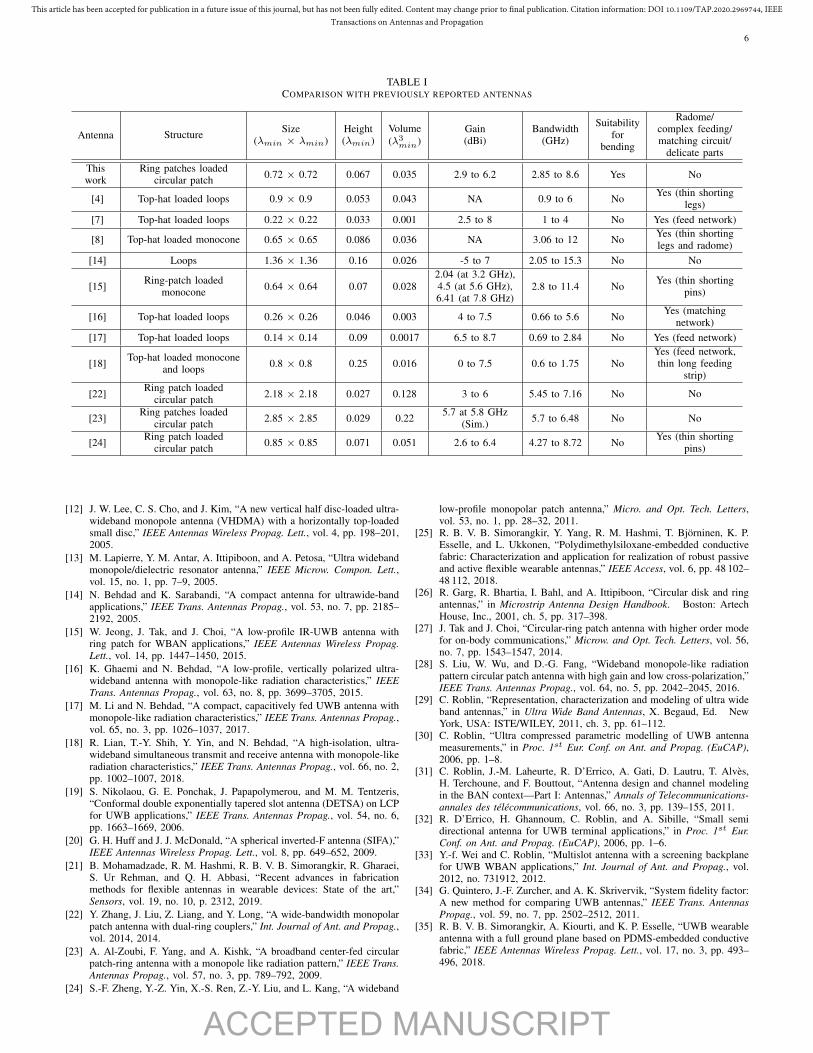
Table I shows the properties of the proposed antenna incomparison with the other presented UWB monopole-likepattern antennas and wideband circular patch antennas. Theproposed structure shows an acceptable compromising be-tween the size, height and gain of the antenna. Moreover,while other presented works are based on rigid structures,the proposed work is fabricated using the flexible PDMS-
0.2
0
0.4
0.6
0.81
Φ = 900
300 mm
300 mm
40 mm
40 mm
300 mm
(b)(a)
Tx Case I
Case II
Case III
Rx
180
150
12060
30
0
x
z
Φ
00
Φ
00
Φ
00 Case I
Case IICase III
Fig. 11. (a) SFF analysis setups for the cases when both antennas are flat(Case I), bent along x-axis (Case II), and bent along y-axis (Case III). (b)System fidelity patterns in horizontal plane obtained from simulations.
conductive fabric composite showing measured efficiency ofhigher than 45% for the entire bandwidth. In addition, it doesnot need any extra protection (e.g., radome), matching circuitsand complex feeding networks.
IV. CONCLUSION
In this paper, we have successfully demonstrated for thefirst time a conformal UWB antenna with radiation char-acteristics resemble a vertically-polarized monopole antenna.Such characteristic was achieved by exciting and combiningfour operating modes, TM01, TM02, TM03, and TM04, of anannular-rings loaded circular patch antenna, making the designis completely planar, unlike previously published work inthis area. The proposed antenna was fabricated using PDMS-conductive fabric composite material, thus suitable for con-formal applications, validated through various bending tests.The time-domain analysis also demonstrated that the antennain either conditions, flat or bent, is suitable for UWB pulsetransmission, justified through SFF values of more 86% for aGaussian pulse having a spectrum from 2.95 to 9.2 GHz.
REFERENCES
[1] J. Foerster, E. Green, S. Somayazulu, D. Leeper, I. A. Labs, I. A. Labs,I. Corp, and I. Corp, “Ultra-wideband technology for short-or medium-range wireless communications,” Intel Tech. Journal, vol. 2, pp. 1–11,2011.
[2] A. Fort, C. Desset, P. De Doncker, P. Wambacq, and L. Van Biesen, “Anultra-wideband body area propagation channel model-from statistics toimplementation,” IEEE Trans. Microw. Theory Techn., vol. 54, no. 4,pp. 1820–1826, 2006.
[3] J. Zhang, P. V. Orlik, Z. Sahinoglu, A. F. Molisch, and P. Kinney, “UWBsystems for wireless sensor networks,” Proc. IEEE, vol. 97, no. 2, pp.313–331, 2009.
[4] A. Elsherbini and K. Sarabandi, “Very low-profile top-loaded UWBcoupled sectorial loops antenna,” IEEE Antennas Wireless Propag. Lett.,vol. 10, pp. 800–803, 2011.
[5] D. W. Aten and R. L. Haupt, “A wideband, low profile, shorted top hatmonocone antenna,” IEEE Trans. Antennas Propag., vol. 60, no. 10, pp.4485–4491, 2012.
[6] G. Adamiuk, T. Zwick, and W. Wiesbeck, “UWB antennas for commu-nication systems,” Proc. IEEE, vol. 100, no. 7, pp. 2308–2321, 2012.
[7] N. Behdad, M. Li, and Y. Yusuf, “A very low-profile, omnidirectional,ultrawideband antenna,” IEEE Antennas Wireless Propag. Lett., vol. 12,pp. 280–283, 2013.
[8] M. Koohestani, J.-F. Zurcher, A. A. Moreira, and A. K. Skrivervik, “Anovel, low-profile, vertically-polarized UWB antenna for WBAN,” IEEETrans. Antennas Propag., vol. 62, no. 4, pp. 1888–1894, 2014.
[9] Y. Li, X.-D. Yang, C.-Y. Liu, and T. Jiang, “A sleeve monopole antennawith wide impedance bandwidth for indoor base station applications,”Prog. In Electromagnetics Research C, vol. 16, pp. 223–232, 2010.
[10] B. Mohamadzade and A. Rezaee, “Compact and broadband dual sleevemonopole antenna for GSM, WiMAX and WLAN application,” Microw.and Opt. Tech. Letters, vol. 59, no. 6, pp. 1271–1277, 2017.
[11] M. Ammann and Z. N. Chen, “Wideband monopole antennas for multi-band wireless systems,” IEEE Antennas Propag. Mag., vol. 45, no. 2,pp. 146–150, 2003.
ACCEPTED MANUSCRIPT
This article has been accepted for publication in a future issue of this journal, but has not been fully edited. Content may change prior to final publication. Citation information: DOI 10.1109/TAP.2020.2969744, IEEETransactions on Antennas and Propagation
6
TABLE ICOMPARISON WITH PREVIOUSLY REPORTED ANTENNAS
Antenna Structure Size(λmin × λmin)
Height(λmin)
Volume(λ3min)
Gain(dBi)
Bandwidth(GHz)
Suitabilityfor
bending
Radome/complex feeding/matching circuit/
delicate partsThiswork
Ring patches loadedcircular patch 0.72 × 0.72 0.067 0.035 2.9 to 6.2 2.85 to 8.6 Yes No
[4] Top-hat loaded loops 0.9 × 0.9 0.053 0.043 NA 0.9 to 6 No Yes (thin shortinglegs)
[7] Top-hat loaded loops 0.22 × 0.22 0.033 0.001 2.5 to 8 1 to 4 No Yes (feed network)
[8] Top-hat loaded monocone 0.65 × 0.65 0.086 0.036 NA 3.06 to 12 No Yes (thin shortinglegs and radome)
[14] Loops 1.36 × 1.36 0.16 0.026 -5 to 7 2.05 to 15.3 No No
[15] Ring-patch loadedmonocone 0.64 × 0.64 0.07 0.028
2.04 (at 3.2 GHz),4.5 (at 5.6 GHz),6.41 (at 7.8 GHz)
2.8 to 11.4 No Yes (thin shortingpins)
[16] Top-hat loaded loops 0.26 × 0.26 0.046 0.003 4 to 7.5 0.66 to 5.6 No Yes (matchingnetwork)
[17] Top-hat loaded loops 0.14 × 0.14 0.09 0.0017 6.5 to 8.7 0.69 to 2.84 No Yes (feed network)
[18] Top-hat loaded monoconeand loops 0.8 × 0.8 0.25 0.016 0 to 7.5 0.6 to 1.75 No
Yes (feed network,thin long feeding
strip)
[22] Ring patch loadedcircular patch 2.18 × 2.18 0.027 0.128 3 to 6 5.45 to 7.16 No No
[23] Ring patches loadedcircular patch 2.85 × 2.85 0.029 0.22 5.7 at 5.8 GHz
(Sim.) 5.7 to 6.48 No No
[24] Ring patch loadedcircular patch 0.85 × 0.85 0.071 0.051 2.6 to 6.4 4.27 to 8.72 No Yes (thin shorting
pins)
[12] J. W. Lee, C. S. Cho, and J. Kim, “A new vertical half disc-loaded ultra-wideband monopole antenna (VHDMA) with a horizontally top-loadedsmall disc,” IEEE Antennas Wireless Propag. Lett., vol. 4, pp. 198–201,2005.
[13] M. Lapierre, Y. M. Antar, A. Ittipiboon, and A. Petosa, “Ultra widebandmonopole/dielectric resonator antenna,” IEEE Microw. Compon. Lett.,vol. 15, no. 1, pp. 7–9, 2005.
[14] N. Behdad and K. Sarabandi, “A compact antenna for ultrawide-bandapplications,” IEEE Trans. Antennas Propag., vol. 53, no. 7, pp. 2185–2192, 2005.
[15] W. Jeong, J. Tak, and J. Choi, “A low-profile IR-UWB antenna withring patch for WBAN applications,” IEEE Antennas Wireless Propag.Lett., vol. 14, pp. 1447–1450, 2015.
[16] K. Ghaemi and N. Behdad, “A low-profile, vertically polarized ultra-wideband antenna with monopole-like radiation characteristics,” IEEETrans. Antennas Propag., vol. 63, no. 8, pp. 3699–3705, 2015.
[17] M. Li and N. Behdad, “A compact, capacitively fed UWB antenna withmonopole-like radiation characteristics,” IEEE Trans. Antennas Propag.,vol. 65, no. 3, pp. 1026–1037, 2017.
[18] R. Lian, T.-Y. Shih, Y. Yin, and N. Behdad, “A high-isolation, ultra-wideband simultaneous transmit and receive antenna with monopole-likeradiation characteristics,” IEEE Trans. Antennas Propag., vol. 66, no. 2,pp. 1002–1007, 2018.
[19] S. Nikolaou, G. E. Ponchak, J. Papapolymerou, and M. M. Tentzeris,“Conformal double exponentially tapered slot antenna (DETSA) on LCPfor UWB applications,” IEEE Trans. Antennas Propag., vol. 54, no. 6,pp. 1663–1669, 2006.
[20] G. H. Huff and J. J. McDonald, “A spherical inverted-F antenna (SIFA),”IEEE Antennas Wireless Propag. Lett., vol. 8, pp. 649–652, 2009.
[21] B. Mohamadzade, R. M. Hashmi, R. B. V. B. Simorangkir, R. Gharaei,S. Ur Rehman, and Q. H. Abbasi, “Recent advances in fabricationmethods for flexible antennas in wearable devices: State of the art,”Sensors, vol. 19, no. 10, p. 2312, 2019.
[22] Y. Zhang, J. Liu, Z. Liang, and Y. Long, “A wide-bandwidth monopolarpatch antenna with dual-ring couplers,” Int. Journal of Ant. and Propag.,vol. 2014, 2014.
[23] A. Al-Zoubi, F. Yang, and A. Kishk, “A broadband center-fed circularpatch-ring antenna with a monopole like radiation pattern,” IEEE Trans.Antennas Propag., vol. 57, no. 3, pp. 789–792, 2009.
[24] S.-F. Zheng, Y.-Z. Yin, X.-S. Ren, Z.-Y. Liu, and L. Kang, “A wideband
low-profile monopolar patch antenna,” Micro. and Opt. Tech. Letters,vol. 53, no. 1, pp. 28–32, 2011.
[25] R. B. V. B. Simorangkir, Y. Yang, R. M. Hashmi, T. Bjorninen, K. P.Esselle, and L. Ukkonen, “Polydimethylsiloxane-embedded conductivefabric: Characterization and application for realization of robust passiveand active flexible wearable antennas,” IEEE Access, vol. 6, pp. 48 102–48 112, 2018.
[26] R. Garg, R. Bhartia, I. Bahl, and A. Ittipiboon, “Circular disk and ringantennas,” in Microstrip Antenna Design Handbook. Boston: ArtechHouse, Inc., 2001, ch. 5, pp. 317–398.
[27] J. Tak and J. Choi, “Circular-ring patch antenna with higher order modefor on-body communications,” Microw. and Opt. Tech. Letters, vol. 56,no. 7, pp. 1543–1547, 2014.
[28] S. Liu, W. Wu, and D.-G. Fang, “Wideband monopole-like radiationpattern circular patch antenna with high gain and low cross-polarization,”IEEE Trans. Antennas Propag., vol. 64, no. 5, pp. 2042–2045, 2016.
[29] C. Roblin, “Representation, characterization and modeling of ultra wideband antennas,” in Ultra Wide Band Antennas, X. Begaud, Ed. NewYork, USA: ISTE/WILEY, 2011, ch. 3, pp. 61–112.
[30] C. Roblin, “Ultra compressed parametric modelling of UWB antennameasurements,” in Proc. 1st Eur. Conf. on Ant. and Propag. (EuCAP),2006, pp. 1–8.
[31] C. Roblin, J.-M. Laheurte, R. D’Errico, A. Gati, D. Lautru, T. Alves,H. Terchoune, and F. Bouttout, “Antenna design and channel modelingin the BAN context—Part I: Antennas,” Annals of Telecommunications-annales des telecommunications, vol. 66, no. 3, pp. 139–155, 2011.
[32] R. D’Errico, H. Ghannoum, C. Roblin, and A. Sibille, “Small semidirectional antenna for UWB terminal applications,” in Proc. 1st Eur.Conf. on Ant. and Propag. (EuCAP), 2006, pp. 1–6.
[33] Y.-f. Wei and C. Roblin, “Multislot antenna with a screening backplanefor UWB WBAN applications,” Int. Journal of Ant. and Propag., vol.2012, no. 731912, 2012.
[34] G. Quintero, J.-F. Zurcher, and A. K. Skrivervik, “System fidelity factor:A new method for comparing UWB antennas,” IEEE Trans. AntennasPropag., vol. 59, no. 7, pp. 2502–2512, 2011.
[35] R. B. V. B. Simorangkir, A. Kiourti, and K. P. Esselle, “UWB wearableantenna with a full ground plane based on PDMS-embedded conductivefabric,” IEEE Antennas Wireless Propag. Lett., vol. 17, no. 3, pp. 493–496, 2018.
Related Documents