S.C. Tang and G.T Clement Proceedings of Meetings on Acoustics _________________________________________________________________________________________________________ Vol. 22, 2015 http://acousticalsociety.org/ _____________________________________________________________________________________________ 168th Meeting Acoustical Society of America Indianapolis Indiana 27-31 Oct 2014 Session 2pBA: Biomedical Acoustics _____________________________________________________________________________ 2pBA16. A computerized tomography system for transcranial ultrasound imaging Sai Chun Tang 1 and Gregory T. Clement 2 1 Dept. of Radiology, Harvard Med. School, 221 Longwood Ave., Rm. 521, Boston, MA 02115, [email protected], 2 Dept. of Biomedical Eng., Cleveland Clinic, Cleveland, OH J. Acoust. Soc Am. 136, 2160 (2014); DOI: 10.1121/1.4899815 Hardware for tomographic imaging presents both challenge and opportunity for simplification when compared with traditional pulse-echo imaging systems. Specifically, point diffraction tomography does not require simultaneous powering of elements, in theory allowing just a single transmit channel and a single receive channel to be coupled with a switching or multiplexing network. In our ongoing work on transcranial imaging, we have developed a 512-channel system designed to transmit and/or receive a high voltage signal from/to arbitrary elements of an imaging array. The overall design follows a hierarchy of modules including a software interface, microcontroller, pulse generator, pulse amplifier, high-voltage power converter, switching mother board, switching daughter board, receiver amplifier, analog-to-digital converter, peak detector, memory, and USB communication. Two pulse amplifiers are included, each capable producing up to 400 Vpp via power MOSFETS. Switching is based around mechanical relays that allow passage of 200 V, while still achieving switching times of under 2 ms, with an operating frequency ranging from below 100 kHz to 10 MHz. The system is demonstrated through ex vivo human skulls using 1 MHz transducers. The overall system design is applicable to planned human studies in transcranial image acquisition, and may have additional tomographic applications for other materials necessitating a high signal output. [Work was supported by NIH R01 EB014296.] _____________________________________________________________________________ Page 1

Welcome message from author
This document is posted to help you gain knowledge. Please leave a comment to let me know what you think about it! Share it to your friends and learn new things together.
Transcript

S.C. Tang and G.T Clement
Proceedings of Meetings on Acoustics
_________________________________________________________________________________________________________
Vol. 22, 2015 http://acousticalsociety.org/ _____________________________________________________________________________________________
168th Meeting Acoustical Society of America
Indianapolis Indiana
27-31 Oct 2014
Session 2pBA: Biomedical Acoustics
_____________________________________________________________________________
2pBA16. A computerized tomography system for transcranial ultrasound imaging
Sai Chun Tang1 and Gregory T. Clement2
1Dept. of Radiology, Harvard Med. School, 221 Longwood Ave., Rm. 521, Boston, MA 02115,
[email protected], 2Dept. of Biomedical Eng., Cleveland Clinic, Cleveland, OH J. Acoust. Soc Am. 136, 2160 (2014); DOI: 10.1121/1.4899815
Hardware for tomographic imaging presents both challenge and opportunity for simplification when compared with traditional pulse-echo imaging systems. Specifically, point diffraction tomography does not require simultaneous powering of elements, in theory allowing just a single transmit channel and a single receive channel to be coupled with a switching or multiplexing network. In our ongoing work on transcranial imaging, we have developed a 512-channel system designed to transmit and/or receive a high voltage signal from/to arbitrary elements of an imaging array. The overall design follows a hierarchy of modules including a software interface, microcontroller, pulse generator, pulse amplifier, high-voltage power converter, switching mother board, switching daughter board, receiver amplifier, analog-to-digital converter, peak detector, memory, and USB communication. Two pulse amplifiers are included, each capable producing up to 400 Vpp via power MOSFETS. Switching is based around mechanical relays that allow passage of 200 V, while still achieving switching times of under 2 ms, with an operating frequency ranging from below 100 kHz to 10 MHz. The system is demonstrated through ex vivo human skulls using 1 MHz transducers. The overall system design is applicable to planned human studies in transcranial image acquisition, and may have additional tomographic applications for other materials necessitating a high signal output. [Work was supported by NIH R01 EB014296.] _____________________________________________________________________________ Page 1
S.C. Tang and G.T. Clement
P a g e 2
1. Introduction
The potential for the use of ultrasound computed diffraction tomography in medicine has been recognized since its initial development in the early 1980s (Devaney, 1982, 1983, 1985; Devaney and Beylkin, 1984; Harris, 1987; Robinson and Greenleaf, 1986). Yet, despite successful implementation in other areas of acoustics, numerous factors have limited widespread medical use. Such problems include failure of numeric inversion algorithms to provide medically-relevant resolution, a lack of sufficiently fast and practical computing options, the absence of medically-suitable arrays, and limitations in electronic hardware.
Contemporary mathematical work in ultrasound image construction has trended somewhat away from full wave inversion, and has turned rather to nonlinear-based inversion techniques (Feingold et al., 2010), primarily in effort to include effects of higher order scattering. Such approaches, however, suffer from poor computational efficiency and, to date, have found only very limited application in medicine (Ruiter et al., 2012; Wiskin et al., 2012). Though considered on convex boundaries (Haltmeier, 2013), they have also yet to demonstrate an ability to fully treat the transmission problem of acoustics along very complex boundaries at longer wavelengths (Kleinman and Martin, 1988); a condition critical to our relevant application through the skull bone. Our approach, rather, is founded on an extension of traditional forms of diffraction tomography. These forms, however, only construct images using data acquired along so-called “separable boundaries,” such that both sources and receivers are placed along a definite rigid geometry (e.g. a circle or line). For the brain and many other medical problems, however, such symmetric placement is impractical or even impossible.
To partially overcome this limit, a prior method (Devaney, 1986) considered an arbitrary configuration of transmitters and receivers for reconstruction under the condition that the local radius of curvature be much larger than a wavelength. This restriction, however, limits its applicability to slowly varying surfaces. Conversely, the
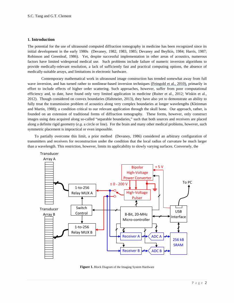
Figure 1. Block Diagram of the Imaging System Hardware
Transducer
Array A
1‐to‐256
Relay MUX A
Switch
Control
High‐Voltage
Pulser
1‐to‐256
Relay MUX B Receiver A
Receiver B
Transducer
Array B
Bipolar
High‐Voltage
Power Converter
ADC A
ADC B
256 kB
SRAM
USB
Interface
To PC
8‐Bit, 20‐MHz
Micro‐controller
+ 5 V
± 0 ‐ 200 V
S.C. Tang and G.T. Clement
P a g e 3
Kirchoff approximation has been used (Ripoll et al., 2005) in cases where distance scales are much larger than a wavelength. Our approach has conversely been to develop a more general method that does not apply explicit restriction on curvature, imaging wavelength, or distance from the region to be imaged (Clement, 2013). This method, however, requires not only the array conform to the contact surface but also that the elements of the array can be precisely spatially registered.
Considering these requirements for the particular case of transcranial imaging, we have developed a transducer designed to conform to the head surface. Our relatively high Q, air-backed 1-3-composite-based transducer is poorly suited for traditional pulse-echo imaging, and rather has been designed to work with a multi-cycle burst relevant to single-frequency reconstruction. Conformal arrays are, of course, not new (Culjat et al., 2008; McGough et al., 2001; Singh et al., 2007). However, our present design overcomes certain previous limitations pertaining to difficulty in registering the precise relative location of the array surface in 3D space using air ultrasound transducers affixed to the array, thus preventing image reconstruction in all but the most controlled cases.
The present work considers the electronics for practically realizing such imaging. Such a task presents both challenge and opportunity for simplification, as compared with traditional pulse-echo imaging systems. Specifically, point diffraction tomography does not require simultaneous powering of elements, in theory allowing just a single transmit channel and a single receive channel to be coupled with a switching or multiplexing network. To drive our conformal transducer, we have developed a 512-channel system designed to transmit and/or receive a high voltage signal from/to arbitrary elements of an imaging array. The overall design follows a hierarchy of modules including a software interface, microcontroller, pulse generator, pulse amplifier, high-voltage power converter, switching mother board, switching daughter board, receiver amplifier, analog-to-digital converter, peak detector, memory, and USB communication. A pulse amplifier is included, capable producing up to 400Vpp via power MOSFETS. Switching is based around mechanical relays that allow passage of 200V, while still achieving switching times of under 0.5 ms, with an operating frequency ranging from below 100 kHz to 10 MHz. The system operation is tested using a commercial probe, with planned experiments on our conformal array. The overall system design is applicable to planned human studies in transcranial image acquisition, and may have additional tomographic applications for other materials necessitating a high signal output. The details, specific features, and preliminary performance test results of our experimental device are described below.
2. System hardware
1.1 Driving/Reciving electronics
The primary engine for our ultrasound transcranial computerized tomography system, diagramed in Figure 1, consists of 512 channels separated into two 1-to-256 high-voltage multiplexers (MUXs) comprised of fast-response mechanical relays. The two MUXs connect a pulser with a single-pole-double-throw switch (Figure 2) and two receivers - one contained within each of the 256 element blocks – so that any given element within either block can serve as a transmitter and/or receiver. The switch sequence of the two MUXs is determined by the imaging algorithm and controlled by the on-board microcontroller unit (MCU). The whole system is powered by a computer USB port, which also provides communication between the computer and the system, so a separate power source is not necessary.
Figure 3 shows a picture of the main board of the system prototype. The board consists of a high-voltage power supply, a pulser, two receivers, two variable-gain amplifiers (VGAs), two analog-to-digital converters (ADCs) for digitizing the received signals, a high-speed memory module, a USB communication module and an MCU. The high-voltage power converter is capable of generating a pulse train of 1 to 15 cycles with a frequency from less than 100 kHz to 5MHz. The pulse amplifier is made of a half-bridge that can deliver a bipolar pulse train with a voltage level from ±50V to ±200V.

S.C. Tang and G.T. Clement
P a g e 4
Figure 2. Schematic of the Bipolar Pulser
Figure 3. The system prototype
S.C. Tang and G.T. Clement
P a g e 5
There are two receiver channels in the system (Figure 4). Each channel has a VGA in which the gain can be programmed from -30dB to 30dB. The gain of the amplifier is automatically determined by the MCU based on the peak signal level of the received signals. The peak value of the received signal is measured by an embedded peak
detector circuit which is integrated in a complex programmable logic device. The received ultrasound signal is amplified to an appropriate voltage level, digitized to an 8-bit digital signal using a low-cost ADC, and stored in the memory module. The size and address range of the memory for storing the received signals are predetermined. Additional system details are provided in Appendix A.
1.2 TransducerArary
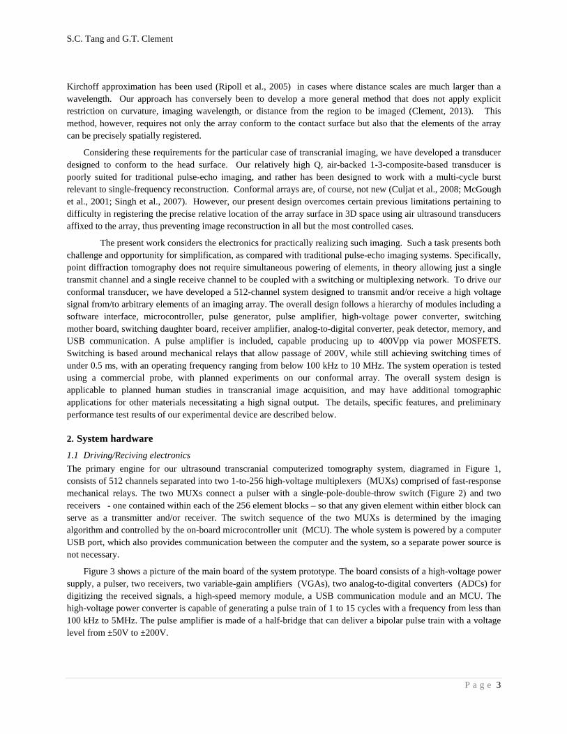
The transducer to be operated by the system (still undergoing construction at the time of this publication) was designed around two key features: (i) Self-calibration. As the acquisition field of view is greatly affected by the extent of the probe along the transducer-tissue interface. It has been recognized that a larger area/volume could be imaged if the probe could be extended along the body, leading to the development of a number of so-called conformal or flexible probe designs. To date, however, none of these devices has been put into practice, largely due to the inability to easily register the relative location of individual elements; a necessary parameter for image reconstruction. Specifically (Figure 4), the transducer array incorporates non-contact (airborne) ultrasound transducers that are used to calibrate the relative location of all elements in the array coupling with the object to be imaged. A unique calculation method has been developed to interpret signals from these non-contact transducers in order determine array orientation and element location. (ii) Mechanical structure. There are numerous applications in medicine and industry for devices that will conform to a desired shape and configuration and then, upon activation, made rigid to freeze the device in the desired shape. This, likewise, is a critical feature for array. As such, we have developed a pivotal housing design containing a locking ability. Though full testing in ongoing, the full design permits the transducer to be affixed in a position that provides good coupling to the imaging object. Furthermore, by preserving its shape upon removal from the object, the self-calibration described above may be performed.
Figure4. One version of the prototype array, shown here unwired (left). In this design, each segment consists of a single 20 mm X 20 mm plate (f = 500kHz) scored into 15 elements. Periodic placement of circular air transducers illustrated in SOLIDWORKS rendering (right) allows for
post-acquisition registration of the transducer.

S.C. Tang and G.T. Clement
P a g e 6
3. Summary
With the overall goal of our project to produce a low cost and effective means of ultrasound tomographic imaging through the skull, we report here on our objective to develop a low cost and portable computerized system. The operation capabilities of the system are based on our prior success with transcranial imaging (Meral and Clement, 2010; White et al., 2009; additional work in submission), as well as our newer approach to tomography (Clement, 2013).
In the present work, a computerized tomography hardware system was completed and tested. This system requires only a single pulser and two receivers in order to operate the entire 512 channel system, thus the system architecture is kept at a very low cost, while also allowing the system to operate with low power consumption. This fact is highlighted by a key feature of the design: the entire system is powered by a computer USB port, not only further simplifying the system, but also eliminating the need for an external power supply. Despite USB powering, the system is capable of delivering high voltage (max, 400 Vpp) bipolar pulse trains to the transducer, resulting in pressure levels necessary to reliably receive transmission through the skull (James et al., 2014). Upon completion of the conformal array, this system will next be applied to producing full images using brain phantoms.
4. Acknowledgements
This work was supported by grant NIH R01 EB014296. We wish to thank Mark Howell for his significant contributions toward the design of the conformal array.
References
Clement, G.T. (2014). “Diffraction tomography on curved boundaries: A projection-based approach,” Inverse Problems, In Press. Preprint available at: arXiv:1312.6601 [math-ph, physics:physics].
Culjat, M.O., Singh, R. S., Utley, C. D., Vampola, S. P., Sharareh, B., Lee, H., Brown, E. R., et al. (2008). “A flexible, conformal ultrasound array for medical imaging,” Stud Health Technol Inform, 132, 95–97.
Devaney, A.J. (1982). “A filtered backpropagation algorithm for diffraction tomography,” Ultrason Imaging, 4, 336–350.
Devaney, A.J. (1983). “A computer simulation study of diffraction tomography,” IEEE Trans Biomed Eng, 30, 377–386.
Devaney, A.J. (1985). “Generalized projection-slice theorem for fan beam diffraction tomography,” Ultrasonic Imaging, 7, 264–275. doi:10.1016/0161-7346 (85)90006-9
Devaney, A.J. (1986). For a stringed musical instrument, US patent US4598366 A, Devaney, A.J., and Beylkin, G. (1984). “Diffraction tomography using arbitrary transmitter and receiver surfaces,”
Ultrasonic Imaging, 6, 181–193. doi:10.1016/0161-7346 (84)90025-7 Feingold, S., Gessner, R., Guracar, I.M., and Dayton, P.A. (2010). “Quantitative volumetric perfusion mapping of
the microvasculature using contrast ultrasound,” Invest Radiol, 45, 669–674. doi:10.1097/RLI.0b013e3181ef0a78
Haltmeier, M. (2013). “Inversion of circular means and the wave equation on convex planar domains,” Computers & Mathematics with Applications, 65, 1025–1036. doi:10.1016/j.camwa.2013.01.036
Harris, J.M. (1987). “Diffraction Tomography with Arrays of Discrete Sources and Receivers,” IEEE Transactions on Geoscience and Remote Sensing, GE-25, 448–455. doi:10.1109/TGRS.1987.289856
James, S.L., Howell, M., Wang, Q., and Clement, G.T. (2014). “A transcranial device and method for detecting cerebellar brain motion,” Ultrasonics Symposium (IUS), 2014 IEEE International, 1237–1240. . Presented at the Ultrasonics Symposium (IUS), 2014 IEEE International. doi:10.1109/ULTSYM.2014.0305
Kleinman, R., and Martin, P. (1988). “On Single Integral Equations for the Transmission Problem of Acoustics,” SIAM J. Appl. Math., 48, 307–325. doi:10.1137/0148016
S.C. Tang and G.T. Clement
P a g e 7
McGough, R.J., Cindric, D., and Samulski, T.V. (2001). “Shape calibration of a conformal ultrasound therapy array,” IEEE Transactions on Ultrasonics, Ferroelectrics and Frequency Control, 48, 494–505. doi:10.1109/58.911732
Meral, F. C., and Clement, G.T. (2010). “128 Element ultrasound array for transcranial imaging,” 2010 IEEE Ultrasonics Symposium (IUS), 1984–1987. . Presented at the 2010 IEEE Ultrasonics Symposium (IUS). doi:10.1109/ULTSYM.2010.5935969
Ripoll, J., Ntziachristos, V., and Madden, K. (2005). Imaging volumes with arbitrary geometries in contact and non-contact tomography, US Patent Application US20050283071 A1, (U.S. Classification 600/425);
Robinson, B. S., and Greenleaf, J. F. (1986). “The scattering of ultrasound by cylinders: Implications for diffraction tomography,” The Journal of the Acoustical Society of America, 80, 40–49. doi:10.1121/1.394081
Ruiter, N.V., Zapf, M., Hopp, T., Dapp, R., Kretzek, E., Birk, M., Kohout, B., et al. (2012). “3D ultrasound computer tomography of the breast: A new era?,” European Journal of Radiology, Extended abstracts and Abstracts of the Sixth International Congress on MR-Mammography, 81, Supplement 1, S133–S134. doi:10.1016/S0720-048X (12)70055-4
Singh, R.S., Culjat, M. O., Vampola, S. P., Williams, K., Taylor, Z.D., and Lee, H. (2007). “P3D-6 Simulation, Fabrication, and Characterization of a Novel Flexible, Conformal Ultrasound Transducer Array,” IEEE Ultrasonics Symposium, 2007, 1824–1827. . Presented at the IEEE Ultrasonics Symposium, 2007. doi:10.1109/ULTSYM.2007.459
White, P.J., Whalen, S., Tang, S. C., Clement, G.T., Jolesz, F., and Golby, A.J. (2009). “An intraoperative brain shift monitor using shear mode transcranial ultrasound: preliminary results,” J Ultrasound Med, 28, 191–203.
Wiskin, J., Borup, D.T., Johnson, S.A., and Berggren, M. (2012). “Non-linear inverse scattering: High resolution quantitative breast tissue tomography,” J Acoust Soc Am, 131, 3802–3813. doi:10.1121/1.3699240
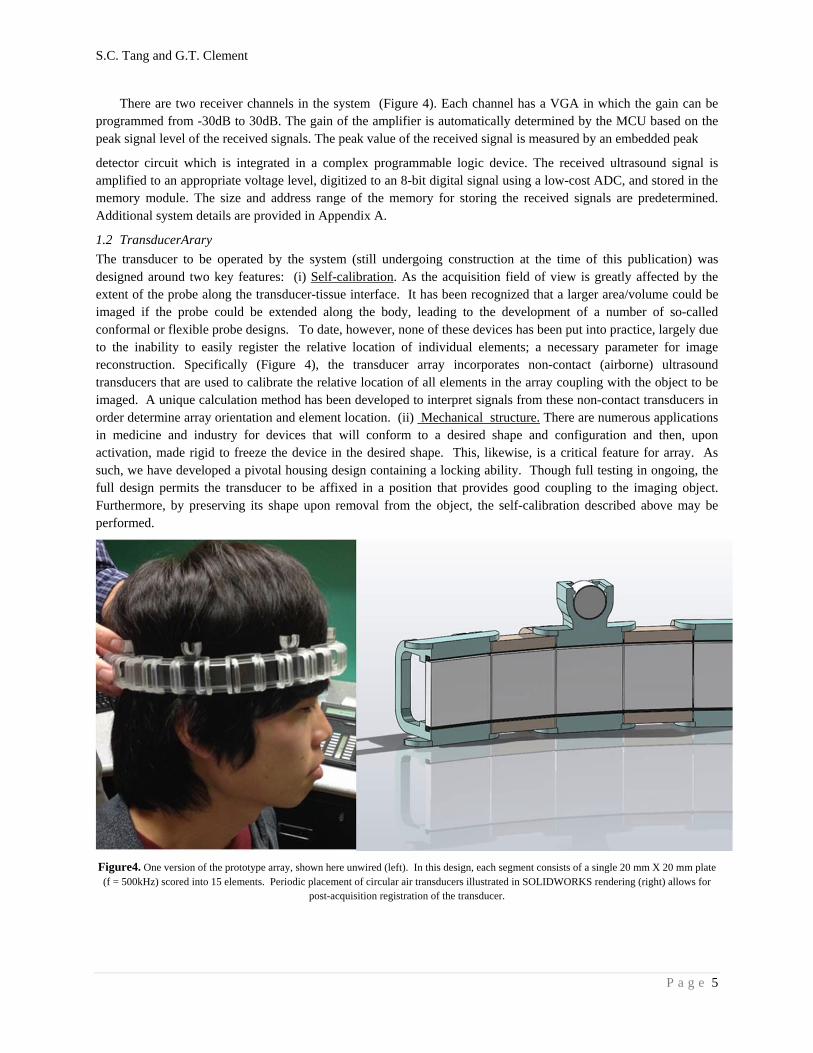
Appendix A. Additional system details
A1: 1-to-256 Relay MUX. A single element is selected simultaneously and can be changed based on the relay response tome of < 0.5 ms. Power consumption of the relay coil is 0.05 W.
.

S.C. Tang and G.T. Clement
P a g e 8
A2: Power Converter. Biopolar converter steps up voltage from +5V to +200V for input to the pulser (Figure 2). Output voltage is set by a user interface. The converter is shut down upon
receive in order to eliminate switching noise.
A3: Receiver Amplifier. Gain of the VGA is determined by introducing a pulsing/receiving action before each sonication. Automation gain control can reduce digitization noise. A low-cost 8-bit ADC is used.
Related Documents


