arXiv:1011.2861v1 [q-bio.NC] 12 Nov 2010 manuscript No. (will be inserted by the editor) A Comprehensive Workflow for General-Purpose Neural Modeling with Highly Configurable Neuromorphic Hardware Systems Daniel Brüderle · Mihai A. Petrovici · Bernhard Vogginger · Matthias Ehrlich · Thomas Pfeil · Sebastian Millner · Andreas Grübl · Karsten Wendt · Eric Müller · Marc-Olivier Schwartz · Dan Husmann de Oliveira · Sebastian Jeltsch · Johannes Fieres · Moritz Schilling · Paul Müller · Oliver Breitwieser · Venelin Petkov · Lyle Muller · Andrew P. Davison · Pradeep Krishnamurthy · Jens Kremkow · Mikael Lundqvist · Eilif Muller · Johannes Partzsch · Stefan Scholze · Lukas Zühl · Christian Mayr · Alain Destexhe · Markus Diesmann · Tobias C. Potjans · Anders Lansner · René Schüffny · Johannes Schemmel · Karlheinz Meier Received: date / Accepted: date Abstract In this paper we present a methodological frame- work that meets novel requirements emerging from upcom- ing types of accelerated and highly configurable neuromor- D. Brüderle · O. Breitwieser · J. Fieres · A. Grübl · D. Husmann de Oliveira · S. Jeltsch · K. Meier · S. Millner · E. Müller · P. Müller · V. Petkov · M. A. Petrovici · T. Pfeil · J. Schemmel · M. Schilling · M. Schwartz · B. Vogginger Kirchhoff Institute for Physics Ruprecht-Karls-Universität Heidelberg, Germany Tel.: +49 6221 549813 E-mail: [email protected] Present address of M. Schilling Robotics Innovation Center, DFKI Bremen, Germany A. P. Davison · A. Destexhe · L. Muller Unité de Neuroscience, Information et Complexité, CNRS, Gif sur Yvette, France M. Diesmann RIKEN Brain Science Institute and RIKEN Computational Science Research Program, Wako-shi, Japan Bernstein Center for Computational Neuroscience, Universität Freiburg, Germany M. Ehrlich · C. Mayr · J. Partzsch · S. Scholze · R. Schüffny · K. Wendt · L. Zühl Institute of Circuits and Systems, Technische Universität Dresden, Ger- many J. Kremkow Bernstein Center Freiburg, University of Freiburg, Germany P. Krishnamurthy · A. Lansner · M. Lundqvist Computational Biology, KTH Stockholm, Sweden E. Muller Brain Mind Institute, Ecoles Polytechniques Federales de Lausanne, Switzerland T. C. Potjans Institute of Neuroscience and Medicine (INM-6), Research Center Jülich, Germany RIKEN Computational Science Research Program, Wako-shi, Japan phic hardware systems. We describe in detail a device with 45 million programmable and dynamic synapses that is cur- rently under development, and we sketch the conceptual challenges that arise from taking this platform into opera- tion. More specifically, we aim at the establishment of this neuromorphic system as a flexible and neuroscientifically valuable modeling tool that can be used by non-hardware- experts. We consider various functional aspects to be cru- cial for this purpose, and we introduce a consistent workflow with detailed descriptions of all involved modules that im- plement the suggested steps: The integration of the hardware interface into the simulator-independent model description language PyNN; a fully automated translation between the PyNN domain and appropriate hardware configurations; an executable specification of the future neuromorphic sys- tem that can be seamlessly integrated into this biology-to- hardware mapping process as a test bench for all software layers and possible hardware design modifications; an eval- uation scheme that deploys models from a dedicated bench- mark library, compares the results generated by virtual or prototype hardware devices with reference software simula- tions and analyzes the differences. The integration of these components into one hardware-software workflow provides an ecosystem for ongoing preparative studies that support the hardware design process and represents the basis for the maturity of the model-to-hardware mapping software. The functionality and flexibility of the latter is proven with a va- riety of experimental results. Keywords Neuromorphic · VLSI · Hardware · Wafer- Scale · Software · Modeling · Computational Neuroscience · PyNN

Welcome message from author
This document is posted to help you gain knowledge. Please leave a comment to let me know what you think about it! Share it to your friends and learn new things together.
Transcript

arX
iv:1
011.
2861
v1 [
q-bi
o.N
C]
12 N
ov 2
010
manuscript No.(will be inserted by the editor)
A Comprehensive Workflow for General-Purpose Neural Modeling withHighly Configurable Neuromorphic Hardware Systems
Daniel Brüderle · Mihai A. Petrovici · Bernhard Vogginger · Matthias Ehrlich ·
Thomas Pfeil · Sebastian Millner · Andreas Grübl · Karsten Wendt · Eric Müller ·
Marc-Olivier Schwartz · Dan Husmann de Oliveira · Sebastian Jeltsch· JohannesFieres · Moritz Schilling · Paul Müller · Oliver Breitwieser · Venelin Petkov · LyleMuller · Andrew P. Davison · Pradeep Krishnamurthy · Jens Kremkow · MikaelLundqvist · Eilif Muller · Johannes Partzsch· Stefan Scholze· Lukas Zühl ·
Christian Mayr · Alain Destexhe · Markus Diesmann · Tobias C. Potjans · AndersLansner · René Schüffny · Johannes Schemmel· Karlheinz Meier
Received: date / Accepted: date
Abstract In this paper we present a methodological frame-work that meets novel requirements emerging from upcom-ing types of accelerated and highly configurable neuromor-
D. Brüderle· O. Breitwieser· J. Fieres· A. Grübl · D. Husmann deOliveira · S. Jeltsch· K. Meier · S. Millner · E. Müller · P. Müller ·V. Petkov · M. A. Petrovici · T. Pfeil · J. Schemmel· M. Schilling ·
M. Schwartz· B. VoggingerKirchhoff Institute for PhysicsRuprecht-Karls-Universität Heidelberg, GermanyTel.: +49 6221 549813E-mail: [email protected]
Present addressof M. SchillingRobotics Innovation Center, DFKI Bremen, Germany
A. P. Davison· A. Destexhe· L. MullerUnité de Neuroscience, Information et Complexité, CNRS, Gif surYvette, France
M. DiesmannRIKEN Brain Science Institute and RIKEN Computational ScienceResearch Program, Wako-shi, JapanBernstein Center for Computational Neuroscience, UniversitätFreiburg, Germany
M. Ehrlich · C. Mayr · J. Partzsch· S. Scholze· R. Schüffny ·
K. Wendt· L. ZühlInstitute of Circuits and Systems, Technische UniversitätDresden, Ger-many
J. KremkowBernstein Center Freiburg, University of Freiburg, Germany
P. Krishnamurthy· A. Lansner· M. LundqvistComputational Biology, KTH Stockholm, Sweden
E. MullerBrain Mind Institute, Ecoles Polytechniques Federales de Lausanne,Switzerland
T. C. PotjansInstitute of Neuroscience and Medicine (INM-6), Research CenterJülich, GermanyRIKEN Computational Science Research Program, Wako-shi, Japan
phic hardware systems. We describe in detail a device with45 million programmable and dynamic synapses that is cur-rently under development, and we sketch the conceptualchallenges that arise from taking this platform into opera-tion. More specifically, we aim at the establishment of thisneuromorphic system as a flexible and neuroscientificallyvaluable modeling tool that can be used by non-hardware-experts. We consider various functional aspects to be cru-cial for this purpose, and we introduce a consistent workflowwith detailed descriptions of all involved modules that im-plement the suggested steps: The integration of the hardwareinterface into the simulator-independent model descriptionlanguage PyNN; a fully automated translation between thePyNN domain and appropriate hardware configurations; anexecutable specification of the future neuromorphic sys-tem that can be seamlessly integrated into this biology-to-hardware mapping process as a test bench for all softwarelayers and possible hardware design modifications; an eval-uation scheme that deploys models from a dedicated bench-mark library, compares the results generated by virtual orprototype hardware devices with reference software simula-tions and analyzes the differences. The integration of thesecomponents into one hardware-software workflow providesan ecosystem for ongoing preparative studies that supportthe hardware design process and represents the basis for thematurity of the model-to-hardware mapping software. Thefunctionality and flexibility of the latter is proven with a va-riety of experimental results.
Keywords Neuromorphic· VLSI · Hardware· Wafer-Scale· Software· Modeling· Computational Neuroscience·PyNN

2
1 Introduction
Neuroscience and Technology
Advances in neuroscience have often gone hand in handwith significant progress in the applied technologies, toolsand methods. While the experimental investigation of livingneural tissue is indispensable for the generation of a detailedknowledge base of the brain, from which understanding ofunderlying principles can emerge, technological difficultieshave always imposed limits to this endeavor. Until today itis not possible to study relevant observables in a sufficientlylarge fraction of brain tissue under realistic conditions andwith a spatiotemporal resolution that is high enough to fullycapture – and possibly consistently explain – the mecha-nisms of higher order brain functions.
Therefore, in neuroscience, like in any other researchfield on dynamical systems that cannot be fully exploredby experimental methods, models represent an indispens-able approach to test hypotheses and theories on the realsubject of interest. However, even neural modeling is sig-nificantly constrained and influenced by the set of avail-able technologies. The spectrum of feasible experimentalsetups, in particular incomputational neuroscience, directlydepends on the accessible computational power. The diffi-culty of efficiently mapping the massive parallelism of neu-ral computation in biological tissue to a limited number ofdigital general purposeCPUs is a crucial bottleneck in thedevelopment of large-scale computational models of neuralnetworks, where statistics-intensive analyses or long-termobservations of network dynamics can become computa-tionally extremely expensive (see e.g. Morrison et al, 2005;Brette et al, 2006; Morrison et al, 2007).
Neuromorphic Hardware
For an alternative modeling approach, the so-calledneuro-morphic engineering, the technology-driven nature is evenmore obvious. In a physical, typically silicon form, neuro-morphic devices mimic the structure and emulate the func-tion of biological neural networks. This branch of neuro-science has its origins in the 1980s (Mead and Mahowald,1988; Mead, 1989, 1990), and today an active community isworking on analog or mixed-signalVLSI1 models of neuralsystems (for reviews see e.g. Renaud et al, 2007; Indiveriet al, 2009).
Dedicated implementations of said computational mod-els are typically more power efficient compared to generalpurpose architectures and are well suited for e.g. embed-ded controllers of autonomous units like robots. Fault toler-ance features observed in biological neural architecturesareexpected to apply to corresponding neuromorphic hardware
1 Very Large Scale Integration
implementations as well. This fact can offer one importantway to create reliable computing components on the basisof future nano-scale hardware constituents, where currentdesign strategies will run into serious yield problems. More-over, the inherent parallelism of on-chip emulation of neuraldynamics has the potential to overcome the aforementionedscaling limitations of pure software simulations.
Still, until today the focus of neuromorphic projects ismostly very application-specific. The majority of groupsis working on neuromorphic sensors like e.g. silicon reti-nas and visual processing systems (Netter and Franceschini,2002; Delbrück and Liu, 2004; Serrano-Gotarredona et al,2006; Merolla and Boahen, 2006; Fu et al, 2008; Gomez-Rodriguez et al, 2010) or motor control in robotics (Lewiset al, 2000). The requirement of communication with the en-vironment is one important reason for the fact that nearly allneuromorphic devices reported so far are designed to oper-ate in real-time. But even the projects that deal with mimick-ing, studying or applying neural information processing (Vo-gelstein et al, 2007), self-organization (Häfliger, 2007; Mi-tra et al, 2009) or even hybrid setups coupling neuromorphicdevices with living tissue (Bontorin et al, 2007) are usuallyfocused on one type of neural architecture, one anatomicalregion or one function the implemented network is supposedto fulfill.
Two main reasons for this self-limitation of neuromor-phic development are the finite size of every neuromorphicdevice as well as the limited possibilities to change the be-havior of individual cells and the network connection pat-terns once they have been cast into silicon. A typical ap-proach to reduce size limitations is to scale up networksby inter-connecting multiple hardware modules (Costas-Santos et al, 2007; Berge and Häfliger, 2007; Indiveri, 2008;Schemmel et al, 2008). Furthermore, recent advances inneuromorphic development eventually promise to overcomethe limited flexibility of hardware models by offering a suf-ficiently fine-grained configurability of both the neuron pa-rameter values as well as the network connectivity (Indi-veri et al, 2006; Schemmel et al, 2007; Ehrlich et al, 2007;Schemmel et al, 2008; Indiveri et al, 2009; Schemmel et al,2010). This crucial feature allows to consider the utiliza-tion of neuromorphic systems as flexible modeling toolsto approach open neuroscientific questions with new strate-gies (Kaplan et al, 2009; Brüderle and Müller et al, 2009;Brüderle, 2009; Brüderle et al, 2010).
A Novel Methodological Approach
The FACETS2 research project (FACETS, 2010) and its suc-cessor BrainScaleS (BrainScaleS, 2010) aim at a compre-hensive exploitation of the possibilities inherent to thatap-proach. The highly interdisciplinary collaborations gather
2 Fast Analog Computing with Emergent Transient States

3
neurophysiological, theoretical and hardware expertise inorder to develop and operate a large-scale neuromorphic de-vice that can serve as a flexible neural network emulationplatform with hitherto unattained configurability and accel-eration. It is planned to exploit this combination of fea-tures with experimental paradigms that are not realizablewith pure software simulations, like long-term learning stud-ies, systematic parameter explorations and the acquisition ofstatistics for every tested setup.
Following this attempt, one important insight hasemerged that has only rarely been addressed in the liter-ature so far (exceptions are e.g. Dante et al, 2005; Osteret al, 2005): Any hardware device that is complex enough toserve as a useful neural modeling tool is useless without anappropriate software environment that implements a reason-able methodological framework for its operation. For anydeveloped neuromorphic modeling platform, hard- and soft-ware have to form a functional unit. Moreover, the need formethods that have to be applied in order to make the advan-tages of a neuromorphic device accessible to non-hardwareexperts does not only refer to the actualoperationof thedevice itself. Instead, already itsdesign processneeds to besupported and influenced by preparatory studies, e.g. withvirtual versions of the future hardware-software system.
In this publication we summarize the FACETS effortsto create a comprehensive methodological framework pro-viding a workflow aiming to make the innovative FACETSwafer-scale hardware system a generic modeling tool appli-cable to a wide range of neuroscientific questions and acces-sible to the neuroscientific community.
Structure of this Article
This introduction is followed by a description of the com-plete neuromorphic modeling infrastructure. This includesboth the utilized hardware devices and theworkflowthat isin focus of this paper, i.e. the framework of methods andsoftware modules that have been developed for the design-assistance, the benchmarking and the actual operation of theplatform. A third section presents data and results that pro-vide a proof of functionality for the concept as a whole. Var-ious components of the workflow are evaluated, and the per-formance of benchmark model experiments performed withthe complete system is studied and analyzed.
2 The Workflow Components: Modules and Methods
The following section provides an overview over the com-plete infrastructure that has been developed to realize anovel neural modeling concept built around the FACETSneuromorphic hardware system. For this purpose, the neu-romorphic device itself is presented in Section 2.1 on alevel of detail that is appropriate to the method descriptions
that follow. These methods are either implemented by or di-rectly rely on an innovative software framework, which willbe explained in Section 2.2 by means of its structure andconcepts. A significant achievement for the targeted designand development of a harmonizing hardware-software unitforming the modeling platform was the collection of a set ofliterature-based benchmark model experiments, as summa-rized in Section 2.4.
The workflow that has been developed around thesethree main components is schematically depicted in Fig-ure 1: The library of dedicated neuroscientific benchmarkmodels, including descriptions and measures to evaluatetheir correct functionality, has been established by membersof the FACETS research project (FACETS, 2010). For anymodel from within this set, a description on the basis of thesimulator-independent modeling language PyNN (see Sec-tion 2.2.1) is available. The mentioned translation softwarestack performs an automated conversion of these scripts intoappropriate data for the configuration and control of differ-ent hardware or software back-ends. The same stack alsore-translates the resulting hardware output into the domainof its biological interpretation. During the development andoptimization phase of the FACETS wafer-scale hardwaresystem, an elaborate virtual version of the device (see Sec-tion 2.3) serves as a test bench for the development and tun-ing of all involved translation software modules.
In addition to the virtual wafer-scale device, a purelychip-based neuromorphic system (see Section 2.1.5) pro-vides important information about characteristics of cir-cuits planned to be implemented in the wafer-scale system.These ASICs thereby support the wafer-scale design pro-cess and the development of possible strategies to compen-sate unavoidable phenomena like transistor-level variationsor noise. The outputs of all applied hardware or virtual hard-ware back-ends are compared with the target output descrip-tions included with the models in the benchmark library andwith reference experiments on pure software simulators. Theremaining differences are analyzed, as is exemplarily pre-sented in Section 3.1.
In an ongoing optimization flow, the benchmark mod-els are repeatedly mapped to the still evolving hardwaresubstrate with the likewise continuously optimized softwareframework. The iteratively applied result analyses providethe fundament for improvements that close the workflowloop: The hardware design, the biology-to-hardware trans-lation modules and optionally even the models themselvesare modified such that the functional effects of remainingdistortions caused by the model-to-hardware mapping pro-cess are minimized.
Hence, the first application of the presented workflow isto take novel types of hardware devices into operation. Fur-thermore, it can serve as a basic methodological paradigmfor the actual target application of neuromorphic systems,

4
Difference ?
Analysis
- Model DistortionCompensation Methods
BioGraph
Description of
Network Distortionscaused by Translation
Acc
ura
te
Dis
tort
ed
Benchmark Library
Performance Evaluation Measures
Target Output
Descriptors for
Model A
Target Output
Descriptors for
Model B
Target Output
Descriptors for
Model C
Model A Model B Model C
PyNN Descriptions of Benchmark Models
Modeling Language PyNN
Automated Translation
Hardware Configuration, Calibration + Control
Virtual Wafer-Scale
Hardware System
FACETS Chip-Based
Prototype System
SD-RAM
NN
Fig. 1: Optimization workflow towards neural modeling with neuromorphic hardware devices. The main components are1. the highly configurable FACETS neuromorphic hardware devices, 2. the software module stack that performs an auto-mated translation of neural network experiments describedwith the modeling language PyNN into corresponding hardwareconfiguration and control patterns, and 3. a benchmark library that contains a collection of neuroscientific models written inPyNN. For a detailed explanation of the complete flow and all individual steps and components see full text.
i.e. the exploration and optimization of neural architecturesby means of different optimization objectives. These includethe search for computationally powerful structures or for se-tups that can reproduce biologically plausible dynamics.
2.1 The FACETS Hardware System
In the following, the FACETS wafer-scale hardware systemwill be described with focus on conceptual and technical de-tails that are relevant in the context of this article. More in-formation on the hardware setup and circuitry can be foundin Schemmel et al (2008), Ehrlich et al (2007), Millner et al(2010) and Schemmel et al (2010).
At the core of the FACETS wafer-scale hardware sys-tem (see Figure 2) is an uncut wafer built from mixed-signal ASICs3, namedHigh Input Count Analog Neural Net-work chips (HICANNs, Schemmel et al, 2008), that pro-vide a highly configurable substrate which physically emu-lates adaptively spiking neurons and dynamic synapses. Theintrinsic time constants of these VLSI model circuits aremultiple orders of magnitude shorter than their biologicaloriginals. Consequently, the hardware model evolves with aspeedup factor of 103 up to 105 compared to biological realtime, the precise value depending on the configuration of thesystem.
3 Application Specific Integrated Circuit

5
In addition to a high-bandwidth asynchronous on-waferevent communication infrastructure, full custom digital off-wafer ASICs provide terminals for a packet-based multi-purpose communication network (Scholze et al, 2010).These so calledDigital Network Chips (DNCs)are backedby a flexible FPGA4 design that handles the packet routing(Hartmann et al, 2010). The communication infrastructureis illustrated in Figure 5. See Section 2.1.3 for details on theinter-chip communication scheme.
A full wafer system will comprise 384 interconnectableHICANNs, each of which implements more than 100,000programmable dynamic synapses and up to 512 neurons, re-sulting in a total of approximately 45 million synapses andup to 200,000 neurons per wafer. The exact number of neu-rons depends on the configuration of the substrate, which al-lows to combine multiple neuron building blocks to increasethe input count per cell.
2.1.1 Composition of the FACETS Hardware System
The wafer as the main component for the FACETS wafer-scale hardware system has to be embedded into a frame-work that provides the electrical integration as well as themechanical stability. The wafer has a diameter of 20 cm andwill be placed into an aluminum plate which also serves asa heat sink. A multi-layer Printed Circuit Board (PCB) isplaced on top of the wafer. This PCB has to provide thefan-out of 1500 impedance-controlled differential pairs and- in the worst case - has to deliver a total electrical powerof 1000 Watts to the wafer. A 14-layer fine pitch board withlaser drilled micro-vias and a total size of 430 mm x 430 mmmeets these requirements. The PCB will be clamped to analuminum frame that is also used as a platform for com-munication devices such as the 48 DNCs and the 12 FPGAboards (see Section 2.1.3). Figure 2 shows a 3-D drawing ofthe hardware composition. All depicted electrical and me-chanical components are custom-made by FACETS projectmembers.
2.1.2 The HICANN Building Block
The HICANN building block shown in Figure 3 is the neu-romorphic ASIC of the FACETS wafer-scale hardware sys-tem. The inter-chip communication scheme is explained inSection 2.1.3.
Simplifying, the HICANN can be divided into fourparts: the neuron circuits with their analog parameter stor-age based on floating gate technology (Lande et al, 1996),an array of 114688 dynamic synapses and theLayer 1 (L1)bus system interconnecting HICANNs on a wafer. The hard-ware neurons implemented by the HICANN building blocks(Millner et al, 2010) can emulate the adaptive exponential
4 Field Programmable Gate Array
A
C
D
B
Fig. 2: The FACETS wafer-scale hardware system: Wafer(A) comprising HICANN building blocks and on-wafercommunication infrastructure, wafer bracket (B), top frame(C) and digital inter-wafer and wafer-host communicationmodules (D).
integrate-and-fire neuron model (AdEx, Brette and Gerstner,2005) which can produce complex firing patterns observedin biology (see e.g. Markram et al, 2004; Destexhe, 2009),like spike-frequency-adaptation, bursting, regular spiking,irregular spiking and transient spiking, by tuning a limitednumber of parameters (Naud et al, 2008).
A AB BC C
D
Fig. 3: A photograph of the HICANN building block withsynapse arrays (A), neurons (B), floating-gate arrays (C) andL1 routing (D).
The model can be described by the following two differ-ential equations for the membrane voltageV and the adapta-tion variablew and a reset condition specified further below:
−CmdVdt
= gl(V −E1)−gl∆te
(
V−Vt∆t
)
+w
+ ge(t)(V −Ee)
+ gi(t)(V −Ei) , (1)
−τwdwdt
= w−a(V −El) . (2)

6
Cm, gl , ge andgi are the membrane capacitance, the leak-age conductance and the conductances for excitatory andinhibitory synaptic inputs, wherege andgi depend on timeand on the inputs from other neurons.El , Ei andEe are theleakage reversal potential and the synaptic reversal poten-tials. The parametersVt and ∆t are the effective thresholdpotential and the threshold slope factor. The time constantof the adaptation variable isτw. The adaptation parameterahas the dimension of a conductance.
If the membrane voltage crosses a certain threshold volt-ageΘ , the neuron is reset:
V → Vreset , (3)
w → w+b . (4)
The parameterb is responsible for spike-triggered adapta-tion.
A neuron can be constructed out of up to 64 so-calleddenmemcircuits, each implementing the dynamics of theAdEx model and being connected to up to 224 synapses.This way a neuron could have synaptic inputs from up to14,336 other cells. Additionally, depressing and facilitatingmechanisms of short-term synaptic dynamics (for a reviewsee Zucker and Regehr, 2002) are implemented. A purelychip-based FACETS hardware implementation of this fea-ture is described and applied in Bill et al (2010).
Hebbian Learning in the FACETS HardwareLong-termHebbian learning in the FACETS hardware devices is imple-mented in every synapse as spike-timing-dependent plastic-ity (STDP, reviewed e.g. in Morrison et al, 2008). To ensurehigh flexibility in terms of mappable neuronal networks eachneuron in hardware needs an appropriate number of synapticinputs. However, due to limited die area, a trade-off betweenthe number of synapses and the chip resources for a singlesynapse has to be made.
To achieve a minimal circuit size for the synapses, lo-cal correlation measurements and the local synaptic weightstorage are separated from global weightupdate controllers(Schemmel et al, 2007, 2006). Causal and acausal correla-tions between pre- and post-synaptic spikes determine thetemporal factor of the STDP rule described in Schemmelet al (2004) and are accumulated locally until they are pro-cessed by the update controller. Synaptic weights are storedlocally as digital values with a four-bit resolution each. Thisresolution is again a trade-off between precision and chipresources and requires several correlated events to reach thenext discrete weight value. If a sufficient amount of corre-lations is accumulated, the discrete weight is updated bythe update controller. Since many synapses share one updatecontroller a weight update is performed periodically with afrequency that has an upper limit determined by the circuitry(Schemmel et al, 2006). Since a reduced symmetric nearest-neighbor spike pairing scheme turned out to be one feasible
approach for describing biological measurements (Burkittet al, 2007; Morrison et al, 2008), this specific plasticitymechanism has been chosen to be implemented in hardwareto further reduce the size of a synapse. Update controllersare modifying the synaptic weights by using look-up tablesthat are listing, for each discrete weight value, the resultingweight values in case of measured causal or acausal corre-lations. These look-up tables can be adapted to the weight-dependent factor of any STDP rule.
With respect to more complex plasticity mechanisms, anextension to STDP rules with additional input parameters,e.g. membrane potentials or spike rates, is currently underdevelopment.
Parameter MemoriesIn contrast to most other systems, theFACETS wafer-scale hardware deploys analog floating gatememories similar to cells developed by Lande et al (1996) asstorage devices for the analog parameters. Due to the smallsize of these cells, most parameters can be provided individ-ually for a single neuron circuit. This way, matching issuescan be counterbalanced, and different types of neurons canbe implemented on a single chip.
As a starting point for the parameter ranges, parametersfrom Brette and Gerstner (2005) and Destexhe et al (1998)have been used. The chosen ranges allow leakage time con-stantsτmem=Cm/gl at an acceleration factor of 104 between1 ms and 588 ms and an adaptation time constantτw between10 ms and 5 s in terms of biological real time. The parame-ters used by Pospischil et al (2008), for example, lie easilywithin this range.
A substantial amount of digital memories is integratedin the chip, dominated by the synapse RAM. Each of the114,688 synapses has 8 bit memory cells for weight and ad-dress storage. For the whole wafer, the synapse RAM aloneis 38 MB large. Figure 4 shows the partitioning of the pa-rameter memory on a HICANN building block. To comparethe analog floating gates to normal digital memory, each cellhas been counted as 10 bit, since this is the number of bitsneeded to program it.
Synapses
Floating Gates
Other
87%
12%
1%
Fig. 4: Sector diagram of the parameter space to configureone HICANN chip. For a full wafer, the configuration datavolume is 44 MB large.

7
Fig. 5: Communication structure on a wafer module of the FACETS wafer-scale hardware system. Neural activity is trans-ported horizontally (dark gray) and vertically (light gray) via asynchronous L1 buses on the HICANN building blocks.Repeater circuits at the edges of these blocks allow for a distribution of the buses over the whole wafer. Off-wafer connec-tivity is established by the L2 network via DNCs and FPGAs. Itinterfaces the L1 buses on the HICANN building blocks.Several wafer modules can be interconnected using routing functionality between the FPGAs via Ethernet switches.
2.1.3 Communication Infrastructure
The communication infrastructure of the FACETS wafer-scale hardware is illustrated in Figure 5. Pulse communi-cation is generally based on the digital transmission of neu-ral events representing action potentials, but a distinction intwo network layers can be made. An asynchronous, serialprotocol, namedLayer 1 (L1)utilized by HICANNs at awafer level provides intra-wafer action potential transmis-sion on a high density direct interconnection grid. A secondone, namedLayer 2 (L2), deploys the DNCs and FPGAs forsynchronous, packet-based, intra and inter-wafer communi-cation and - compared to L1 - establishes a more flexiblerouted network of lower density. To cope with inevitablejitter in routing delay, a time stamp is transmitted togetherwith the address within the data packets of this network. APC cluster that handles the mapping, configuration and con-trol process described in Section 2.2 as well as the playbackand recording of external stimuli to the neural network isconnected to the FPGAs via multi-Gigabit Ethernet.
Activity is injected into the L1 network in the formof 6 bit serial pulse address packets by neurons that con-nect to the horizontal buses. Sparsely populated passiveswitch matrices at the intersections of horizontal and ver-tical buses pass the data to the vertical buses. Further sparseswitch matrices connect to horizontal lines feeding synapsedrivers that act as data sinks to the network. While crossingHICANN block boundaries the signals are refreshed by re-peater circuits with active re-timing that are capable of driv-ing the signals across one HICANN block. The sparsenessof the switch matrices is chosen such that the repeater cir-cuits are not overloaded while still providing maximum flex-
ibility for implementing various neural network topologies(see Fieres et al, 2008 and Schemmel et al, 2010).
Connectivity between the HICANN blocks is estab-lished by edge connecting them in the layout. As illustratedin Figure 5, this is only possible for eight HICANNs locatedwithin one reticle. A reticle is the largest producible unitonthe wafer and no connections can be formed between reticlesduring standard CMOS fabrication. Wafer-scale connectiv-ity is obtained using a post-processing method developed inthe FACETS project. It offers two additional routing layersthat can cover the whole wafer. By means of this technique,an inter-reticle connection pitch well below 10µm can beachieved which facilitates the required connectivity. Further-more, large landing pads are formed by the post-processingthat connect the wafer to the system PCB via elastomericstripe connectors (see Figure 2 and Schemmel et al, 2010).
These stripe connectors are used to deliver all requiredpower to the wafer. Additionally, they connect high speedcommunication signals between the HICANNs and theDNCs5. This high speed communication interface transportsconfiguration data as well as the above-mentioned L2 datapackets. L2/L1 protocol conversion is performed inside theHICANN blocks, where L2 activity can either be injectedto or read from the L1 network (see Figure 5). The trans-port of the L2 packets is handled by the DNCs, which alsoimplement a time-stamp based buffering and heap-sort al-gorithm (Scholze et al, 2010). Together with routing logicinside the FPGAs, the DNC-FPGA L2 network fulfills theQoS6 demands (Philipp et al, 2009) for spiking neural net-
5 For completeness it should be noted that also analog signals,e.g. selectable neuron membrane voltages, are transportedthrough thestripe connectors.
6 Quality of Service

8
works, i.e. a constant delay at a low pulse loss rate. This isalso true for inter-wafer connections routed through Ether-net switches connected to the FPGAs.
2.1.4 Host Interface
The packet communication between wafer and host com-puter passes through several layers: DNCs, FPGA controllerboards and a Gigabit Ethernet layer (Norris, 2003) have tobe traversed. As each of the twelve FPGA controller boards(see C in Figure 2) comprises two Gigabit ports dedicatedfor host communication, a total bandwidth of 24GBit/s can beachieved. Standard networking switches concentrate theselinks into the required number of 10GBase-LX4 (Horak,2007) upstream ports. A standard PC cluster equipped withadequate network interface cards handles the traffic. A cus-tom design ARQ7-style (Fairhurst, 2002) protocol providesa reliable communication channel between the host com-puter and the hardware system. The FPGA controller boardsact as remote terminals for these ARQ communication chan-nels, but also provide system control functionality.
During experiments, most communication data – basi-cally spike events – flow directly between host computerand FPGA controller boards. In contrast to this, in the initialsetup stage almost all traffic – i.e. the system configurationdata – is dedicated to wafer communication. In this case, theFPGA controllers act as simple transmission nodes betweenhost computer and wafer. Both operational stages imposehigh demands on the communication bandwidth. The ini-tial configuration space consumes around 50MB (see Fig-ure 4). Every spike event is represented by a 15-bit timestamp and a 12-bit data field, comprising both DNC andHICANN identifiers. Thus, during an experiment approx-imately 1GEvent/s can be transported to and from the hostcomputer. At a speedup factor of 104, the corresponding to-tal spike rate in the biological time domain is 100 kHz perwafer.
To meet these requirements set by the hardware scale,acceleration factor and modeling constraints, a highly scal-able software implementation of the communication proto-col was developed (see Section 2.2.10 and Schilling, 2010).This multi-threaded protocol stack already provides a zero-copy API8 to the upper software layers.
Furthermore, to support future applications, such as in-terfacing the FACETS hardware system to simulated envi-ronments which provide sensor output related to motor in-put, low round-trip times between these components are cru-cial. Such classes of in-the-loop experiments demand low la-tency communication and high bandwidth at the same time.
7 Automatic Repeat reQuest8 Application Programming Interface
2.1.5 Chip-Based Neuromorphic System
On the development path towards the FACETS wafer-scalehardware platform, a purely chip-based neuromorphic sys-tem has been designed and built (Schemmel et al, 2006,2007) and is in active use (Kaplan et al, 2009; Brüderle andMüller et al, 2009; Brüderle et al, 2010; Bill et al, 2010).It implements time-continuous leaky integrate-and-fire cellswith conductance-based synapses and both a short-term anda long-term plasticity mechanism as described above forthe wafer-scale device. Up to 16 of these ASICs, each ofwhich provides 384 neurons and 105 configurable and plas-tic synaptic connections, can be operated individually or in-terconnected via a supporting backplane board. This boardis connected via a single Gigabit Ethernet link to a hostcomputer, through which multiple users can access and usethe neuromorphic devices in parallel. The possibility of re-motely accessing the chips via the Internet in addition tosetting up and running experiments with an available PyNNinterface (see Section 2.2.1 and Brüderle and Müller et al,2009) already now make this system a tool that is usedfor neuromorphic model exploration by users from variouscountries. Many circuit design strategies for the wafer-scalesystem are implemented for testing purposes in this chip-based device, including the STDP correlation measurements(see Section 2.1.2) located in every individual synapse. Ba-sic plasticity studies supporting the design of the wafer-scalesystem, some of which are outlined in Section 2.5.3, in-corporate investigations on the basis of experimental resultsfrom the chip-based devices.
2.2 Software Framework
Figure 6 shows the stack of software modules that will be de-scribed in the following. Its components seamlessly interactin performing an automated translation of arbitrary neuralnetwork experiment descriptions into appropriate data forhardware configuration and control. The same stack also au-tomatically re-interprets the acquired hardware output intoits biological interpretation. The top-level interface offeredto hardware users to describe neural network setups is basedon the simulator-agnostic modeling language PyNN. Theconcept of this approach and its advantages, especially forneuromorphic system operation, will be described in Sec-tion 2.2.1.
The process of mapping a PyNN description onto theconfiguration space of the FACETS hardware systems, in-cluding dedicated representation formats, will be describedin Sections 2.2.2 to 2.2.8. Sections 2.2.9 and 2.3 focus onthe mapping analysis plus its testing and optimization on thebasis of an elaborate virtual version of the wafer-scale hard-ware system. The special performance requirements for thelow-level host-to-hardware communication software and the

9
Fig. 6: Schematic of thehardware abstraction layer, i.e. thestack of software modules for the automated and bidirec-tional translation between PyNN model descriptions and ap-propriate hardware configuration and control patterns. Theindividual modules are: A Python control layer, a mappinglayer that operates on a graph-based data container (Graph-Model), and low-level layers that deliver the generated hard-ware configuration patterns and control sequences via a ded-icated communication protocol.
implemented corresponding solutions are outlined in Sec-tion 2.2.10.
2.2.1 PyNN & NeuroTools
PyNN is a simulator-independent, Python-based languagedesigned for describing spiking neural network models(Davison et al, 2008). It offers functions and classes for thesetup and control of experiments, and it provides standardcell models as well as standardized dimension units. PyNNsupports various software simulators like NEURON (Hinesand Carnevale, 2006; Hines et al, 2009), NEST (Gewaltigand Diesmann, 2007; Eppler et al, 2008), Brian (Goodmanand Brette, 2008) and PCSIM (Pecevski et al, 2009). WithPyNN, which is open source and well documented, a usercan set up a neural network model, run it on any of the sup-ported back-ends without changing the code, and directlycompare the results. This provides the possibility to con-veniently port experiments between different simulators,totransparently share models and results, and to verify dataacquired from different back-ends (see Figure 7).
The integration of the operating software frameworkfor the FACETS hardware system into the PyNN concept(Brüderle and Müller et al, 2009; Brüderle, 2009) is a cru-cial aspect of the presented neuromorphic workflow. Oneimportant motivation for this approach is to create a bridgebetween the communities of neuromorphic engineers andneural modelers, who have been working in rather separateprojects so far. The back-end agnostic concept of PyNN,
now also offering the possibility to port existing experimentsbetween the supported software simulators and the FACETShardware system, allows to benchmark and verify the hard-ware model. The API of PyNN is easy to learn, especiallyfor scientists who have already worked with software sim-ulators. Hence, PyNN represents an optimal way to providenon-hardware experts a convenient interface to work withthe FACETS neuromorphic devices. In general, PyNN in-terfaces to neuromorphic systems make it possible to for-mulate transparent tests, benchmarks and feature requests,and therefore can influence and boost biologically orientedhardware development. They might, eventually, support theestablishment of such emulation devices as useful modelingtools.
On top of PyNN, a library of analysis tools called Neuro-Tools (NeuroTools, 2008) is being developed, which buildsupon the interface and data format standards, but also ex-ploits the possibility to incorporate third-party Python mod-ules e.g. for scientific computing and plotting (Oliphant,2007; Jones et al, 2001; Langtangen, 2008; Hunter, 2007).Thus, for all supported software simulators and for theFACETS neuromorphic hardware systems, all stages of neu-ral modeling experiments - description, execution, resultstorage, analysis and plotting - can be performed fromwithin the PyNN and NeuroTools framework.
Simulations as Reference for Translation and CalibrationThe hardware-specific PyNN approach incorporates quanti-tative bidirectional translation methods between the neuro-morphic system dynamics and the biological domain, bothin terms of electrical variables and the different time do-mains. This translation incorporates calibration routines thatminimize the impact of transistor-level fixed-pattern noiseon the behavior of neural and synaptic circuits. The trans-lation and calibration scheme developed for the FACETShardware systems directly involves reference software sim-ulations for the biologically relevant gauging of hardwareparameters, heavily exploiting the PyNN paradigm of uni-fied setup descriptions. Section 2.2.7 provides more detailson this.
2.2.2 Mapping Process
The mapping process determines a valid routing networkconfiguration and parameter value set as initial setup datafor the FACETS hardware system. This takes into accounttopology constraints between hardware blocks such as con-nectivity, connection counts, priorities and distances aswellas source/target counts. Figure 8 depicts the single steps ofthe mapping process as described by Ehrlich et al (2010).
The mapping is accomplished in the three main steps ofPlacement, RoutingandParameter Transformation & Cal-ibration, with an appropriatePre- and PostProcessingof

10
PyNN
pyNN.pcsim
PyPCSIM
pyNN.brian
Brian
pyNN.hardware.facets
Python Control Layer
pyNN.nest
PyNEST
NEST
SLI
pyNN.neuron
nrnpy
NEURON
pyNN.neuroml
NeuroMLHOC
Simulator-Specific
PyNN Module
Python Interpreter
Native Interpreter
Simulator Kernel
Mapping Process
PCSIMNN
Configuration
Low-Level API & Communication
Fig. 7: Schematic of the simulator-independent modeling language PyNN. Like various established software simulators, theFACETS neuromorphic hardware systems have been integratedinto the PyNN unification and standardization concept.
the configuration data. As the first three main steps are ex-plained in more detail in the following we will shortly sum-marize the functionality of the remaining parts.
Starting with a neural architecture defined via PyNN, thefirst mapping step ofPreProcessingreads in a description ofthe hardware (see Section 2.2.3), described using the novelquery languageGMPath (see Section 2.2.4). It sets up aninternal representation for both the hardware and the bio-logical model in the form of a directed graph calledGraphModel (see Section 2.2.4). Optionally, a so-calledPreMap-pingnetlist of the biological model can be streamed out intoa file. Following placement and routing, the same appliesfor the PostProcessingwith a PostMappingnetlist, whichincludes the possibility to obtain a PyNN script that repre-sents the (possibly distorted) network ultimately realized onthe hardware back-end.
The individual steps of the process are automatically ini-tiated and partly controllable via the PyNN module for theFACETS hardware system. Furthermore a stand-alone soft-ware namedGraViTois provided for the analysis of the map-ping results (see Section 2.2.9).
2.2.3 Internal Hardware Description
Prior to the mapping process we have to define the hard-ware in an abstract manner. For this purpose we utilize thepath languageGMPathto set up an appropriate GraphModel(both described in Section 2.2.4) as a versatile internal rep-resentation.
In Figure 9 a FACETS wafer-scale hardware setup - alsoapplied in Ehrlich et al (2010) - is illustrated. As describedin Section 2.1, the fundamental layer of the FACETS wafer-scale hardware is an array of reticles shown as light graysquares, housing the HICANN circuitry that implementsneural functionality, with a second layer of DNCs above.
The third and topmost layer represents a regular grid ofFPGAs, colored dark gray.
2.2.4 The GraphModel Container
A data model calledGraphModel(Wendt et al, 2008) repre-sents both the targeted biological and the configurable hard-ware structure within the mapping software. It can be char-acterized as a hierarchical hyper graph and consists of ver-tices (data objects) and edges (relationships between the ver-tices). A vertex contains a single data value. An edge can beone of the following types:
hierarchical: models a parent-child relationship, structuringthe model
named: forms a directed and named relation betweenany two vertices in the model
hyper: assigns a vertex to a named edge, characteriz-ing the edge in more detail
The major advantage of this graph approach are the imple-mentation convenience and efficiency as well as the flexibil-ity to achieve the complex requirements from both the bio-logical and the hardware model. Due to the structure of thegraph model it can be easily (de-)serialized, providing saveand restore functionality. Via the path-based query-languageGMPath(Wendt et al, 2010) information can be dynamicallyretrieved from and stored to the models. The GraphModel isused to store all information during the configuration pro-cess, i.e. the models themselves, the mapping, routing andparameter transformation algorithms data and their results.
Figure 10 shows the graph model representation of a bi-ological network (calledBioGraph) and its hardware repre-sentation (calledHardwareGraph), connecting elements vianamed edges after a placement step.

11
Map
pin
g P
roce
ss
GraphModel
Configuration
Low-Level Hardware API & Communication
Python Control Layer
(c) Parameter Transformation
& Calibration
PreMap.sgm
PostProcessingPostMap.sgm
(a) Place
hwinit.pl
(b) Route
PreProcessing
PyNN
Fig. 8: Mapping PyNN neural network model descriptionsonto the configuration space of the wafer-scale hardwaresystem. The three main processing steps, all operating onone unified data container (GraphModel), are (a) the plac-ing of neurons onto the available circuitry, (b) the realiza-tion of synaptic connections by appropriately configuringthe availablerouting infrastructure on the device, and (c) thetransformation of neuron and synapse parameters into cor-responding parameter values offered by the highly config-urable device. The latter step can involve calibration datatotune individual sub-circuits such that the effect of unavoid-able transistor-level variations onto the mapped models isminimized.
The Query Language GMPathTo retrieve information fromand propagate data to the graph models, the path-basedquery languageGMPath was developed, providing a uni-versal interface for placing and routing algorithms as wellas for configuration, visualization and analysis tools (Wendtet al, 2010). Based on so-called navigational steps, a pathrequest can enter the model at any point (node or edge) andaddresses iteratively the logical environment by
· shifting the focus hierarchically up- or downward· shifting the focus back and forth along edges· filtering according names· concatenating sub-queries
The results are lists of nodes or edges and serve the re-questing software as model information input. Because of its
FPGA
DNC
Reticle/HICANNs
Fig. 9: Example FACETS wafer-scale hardware setup fromEhrlich et al (2010): 12 FPGAs control 48 DNCs, which areconnected to 384 HICANN ASICs.
Fig. 10: A simplified example of two graph models, assign-ing neural elements to hardware components.
string based format and the ability to address nodes or edgesunambiguously, the queries can be created conveniently anddynamically at runtime and can be used to extend and mod-ify the models.
Figure 11 exemplarily shows subsequent navigationalsteps of an executed path request, which enters the abstracthardware model at its root, addresses all existing HICANNnodes and finally follows incoming mapping edges to theirorigins, the neurons of the biological model.
2.2.5 Neuron Placement
The process of assigning neural elements like neurons,synapses or their parameters to distinct hardware elementsiscalledplacement. It can be characterized as a multi-objective

12
Fig. 11: An example GMPath request to retrieve all assignedneurons of the biological model.
optimization problem, the solution of which significantlyinfluences the overall mapping results. Typical algorithmicapproaches create clusters of cells with common propertiesthat are mapped to the same HICANN building blocks. Pos-sible optimization objectives are:
· minimize neural input/output variability cluster-wise· minimize neural connection count cluster-wise· comply with parameter limitations· comply with cluster capacities (neural capacity of hard-
ware elements)· minimize routing distances
In order to achieve these objectives with user-definedweightings in acceptable computation time, a force-basedoptimization heuristic was developed. This algorithm bal-ances modeledforces(special implementations of the opti-mization objectives) in ann-dimensional space until an equi-librium is reached and a final separation step assigns dataobjects to clusters with affine properties. Despite this prob-lem being NP-complete, significantly improved results canbe found with this algorithm in an acceptable computationtime, as compared to a fast random placement.
Figure 12 illustrates a placement process, divided intoan optimization step, which sorts the given biological net-work for optimal hardware utilization with regard to the in-put source variability, and an assignment step, defining thephysical realization of neural elements on the hardware sys-tem.
2.2.6 Connection Routing
The routing step allocates and configures the hardware re-sources for establishing the synaptic connections in the al-
Fig. 12: An example placement, divided into an optimizationand assignment step.
ready placed BioGraph. Given the fixed amount of availableresources it is not evident a priori whether arbitrary networktopologies are always perfectly reproducible.
Synaptic connections can in principle be established viathe L1 and L2 infrastructure (see Section 2.1.3). In the ap-proach described here, all intra-wafer connectivity is routedexclusively on L1. The L2 network is reserved for inter-wafer connections in a multi-wafer system.
The intra-wafer routing algorithms were developed inclose cooperation with the wafer design (Fieres et al, 2008).Some hard-wired features of the L1 infrastructure are thuslaid out to optimally suit the routing requirements. The rout-ing itself is performed in two stages. The first stage estab-lishes connections on a HICANN-to-HICANN level via thehorizontal and vertical L1 buses, mainly by configuring thebus repeaters and sparse crossbars (see Figure 5). In the sec-ond stage the signals are routed from the vertical L1 buslanes into the synapse arrays via the sparse switch matri-ces, the synapse drivers and the address decoders of thesynapses, the latter not being shown in Figure 5.
The algorithms were proven in various test scenarios:Homogeneous randomly connected networks with up to16,000 neurons, locally connected networks (according toTao et al, 2004) as well as a model of a cortical column(following Binzegger et al, 2004 and Kremkow et al, 2007)with 10,000 neurons. It turns out that in typical cases onlya small amount of unrouted connections must be accepted,mainly due to limited resources in the second routing stage.However, it was also shown that by decreasing the density ofthe neuron placing the routing can be generally facilitated,at the expense of a larger portion of idle hardware synapses.

13
The routing algorithms proved to be also applicable forthe benchmarks described later in this publication, see Sec-tion 2.4 and Ehrlich et al (2010).
2.2.7 Parameter Transformation
The parameter transformation maps parameters of givenneuron and synapse models into the hardware parameterspace. It is performed HICANN-wise. Biological data isfirst acquired from the so-calledBioGraph of the Graph-Model (see Section 2.2.4) and then transformed into a hard-ware configuration, which is stored back into theHard-wareGraph. For an adequate biology-to-hardware transla-tion several constraints have to be considered, such as hard-ware imperfections and shared or correlated parameters inthe microchip.
For the membrane circuits, a two-step procedure wasdeveloped to translate the 18 biological parameters fromthe PyNN description to the 24 electrical parameters of theHICANN building block. The first step is to scale the biolog-ical neuron model parameters in terms of time and voltage.At this stage, the desired acceleration factor is chosen andapplied to the two time constants of the neuron model. Then,the biological voltage parameters are transformed to matchthe voltage levels of the HICANN building block. The sec-ond step is to translate those intermediate values to appropri-ate hardware parameters. For this purpose, each part of themembrane circuit was characterized in transistor-level sim-ulations, which were used to establish the translation func-tions between the scaled AdEx parameters and their hard-ware counterparts.
However, due to transistor size mismatch in the hard-ware, these translation functions are expected to differ fromneuron to neuron. A calibration software has been developedto automatically parameterize these translation functions foreach neuron. For each neuron model parameter, the soft-ware will send a spectrum of values to the HICANN build-ing block, and measure the resulting membrane potentials ofthe current cell. It will then deduce the corresponding AdExparameters from these measurements, and store the valuepairs into a database. After a given number of measurementpoints, the algorithm will compute the relation between thehardware parameters sent to the floating gates and the AdExparameters, and store this function into the database. Figure13 illustrates the calibration software architecture.
Once the calibration step is done, the database can beused to automatically convert a set of biological neuron pa-rameters to their hardware counterparts, allowing on-the-flyconversion of neuron parameters for the wafer-scale hard-ware system.
Concerning the synapses, there are mainly two restric-tions ensuing from the chip design: 256 synapses of thesame row share the maximal conductancegmax and the short
DatabaseAdEx
Simulation
Hardware
SystemOscilloscope
Floating Gates
Interface
Calibration
Controller
Database
Interface
Oscilloscope
Interface
Fig. 13: Architecture of the calibration software. The maincomponent, the calibration controller, executes the calibra-tion algorithms and communicates with the hardware, theoscilloscope and the database via dedicated interfaces. Thecalibration software also incorporates an AdEx model sim-ulator to compare software and hardware results.
term plasticity mechanism, and weights are restricted to a4-bit resolution. By averaging over all active synapses, thetransformation algorithm determinesgmax and sets the digi-tal weights accordingly, usingstochastic roundingto avoidsystematic errors.
2.2.8 Application of the Mapping Flow onto the FACETSChip-Based System
In order to further demonstrate the versatility of theGraphModel-based mapping flow introduced in Sec-tion 2.2.4, we briefly outline the adoption of this procedureto the operation of the FACETS chip-based systems (seeSection 2.1.5). This integration avoids code redundancyby unifying the previously independent PyNN back-endsand allows to map neural architectures onto inter-connectedchips beyond single-chip boundaries (Jeltsch, 2010). Dueto the flexible design of the mapping framework, the trans-lation of the PyNN description into the biological graphrepresentation (see Section 2.2.2) and the placing of biolog-ical neurons onto their hardware counterparts (see Section2.2.5) could be kept completely unchanged. Necessary ex-tensions were limited to the development of a new internalhardware model that captures all features of the chip-basedsystem as well as adapted versions of the routing and theparameter translation (described in Section 2.2.6 and 2.2.7,respectively) to match the different network topology andelectrical parameters. Together with the low-level event dis-tribution network established by Friedmann (2009), neuralnetwork models can now be scaled to multiple chips.

14
2.2.9 Mapping Analysis and Visualization
The applicationGraph Visualization Tool – GraViToas de-scribed by Ehrlich et al (2010) aids in analyzing the mappingresults. GraViTo, as shown in Figure 14, integrates severalmodules that display graph models in textual and graphicalform and gathers statistical data. One can selectively accesssingle nodes inside the data structure and visualize their con-text, dependencies and relations with other nodes in the sys-tem.
Fig. 14: Screenshot of the GraViTo application.
The example of the GraViTo views shows atree viewonthe left which is utilized to browse the hierarchical structureof the graph model and examine contents and connectionsof individual nodes. The3-D viewon the right provides avirtual representation of the FACETS wafer-scale hardwaresystem for interactively browsing its architecture and con-figuration. It also provides a global overview over the singlehardware components and the networks they form. Variousstatistics such as histograms for utilization of the crossbarsor the synaptic connection lengths are gathered and can bedisplayed.
Another option for a systematic mapping analysis arisesfrom the previously mentioned possibility to re-translatetheconfigured HardwareGraph contents via the mapping edgesthrough the BioGraph into aPostMappingPyNN script. Thisscript intrinsically contains all model distortions caused bythe mapping process, e.g. lost synapses and discretized orclipped parameter values. Exploiting the PyNN concept, itcan then be directly evaluated with a software simulator toextract possible functional consequences of the structuraldistortions, avoiding interferences with other effects like on-wafer communication bandwidth limitations.
2.2.10 Hardware Low-Level Interfacing
A specialized protocol of the class ofselective ARQ9 pro-tocolsis used to provide a fast and reliable communicationchannel with the neuromorphic hardware device. In the OSImodel10 this corresponds to the transport layer.
Configuration and experimental data is bidirectionallytransmitted via two 10GBit/s Ethernet links per FPGA. Inorder to handle up to 2GByte/s of traffic while keeping theload of the host computer as low as possible, several soft-ware techniques have been applied to the protocol imple-mentation. Various features of existing transport protocols,notably TCP, have been implemented, including congestionavoidance, RTT11 estimation and packet routing to keep theconnection in a stable and bandwidth maximizing regime.
In matters of performance the framework is divided intothree mainly independent processingthreads(see Figure 15,receiver threadRX, sender threadTX andresendthread) to
Python Control Layer
PyNN
Mapping Process GraphModel
Co
nfi
gu
rati
on
t
NIC
Shared Memory
Experiment(Configurator/S2Ctrl)
config (GM*)sendST (GM*)recvST (GM*)
FG-C
fg
L1-C
fg
L2-C
fg
FPG
A
Syn
-CfgSpikeTrain SpikeTrain
RX TXResend
Low
-Lev
el
Hard
ware
AP
I &
Co
mm
un
icati
on
Hardware Configuration Classes
Transport Protocol
Fig. 15: Configuration and runtime control steps in the hard-ware abstraction layer: TheExperimentmodule acquires theconfiguration data from the Mapping Process (see Section2.2.2 and Figure 8), generates a hardware-specific represen-tation of this data and triggers the transfer to the hardwaresystem.
9 Automatic Repeat reQuest10 Open Systems Interconnection model11 Round Trip Time

15
exploit the speed-up in execution of modern multiproces-sor systems. Performance critical data, e.g. spike data canbe placed inshared memoryand passed to and from thehardware abstraction layers such as to avoid unnecessarycopying. These shared data structures have to be protectedagainst concurrent accesses which imposes an additionaloverhead in processing time. Thus, to keep the number ofsystem calls and context switches small, access to data lo-cated in shared memory is protected by means of custombuilt user-space fencing and locking methods.
A purely software-stack-based test has been developedthat establishes a reliable ARQ connection between two hostcomputers via 10 Gigabit Ethernet. With a hardware-specificversion of this protocol, i.e. with frame sizing and protocolwindow size, it delivers 10GBit/s (Schilling, 2010).
2.3 Virtual Hardware
An executable specification of the FACETS wafer-scalehardware system serves as a versatile tool not only duringdevice design and optimization, but also as a test bench forall involved software layers. It is a functional model that canbe used to explore the behavior and characteristics of thereal wafer-scale system in its final phase of development.
2.3.1 Implementation
The so-calledvirtual hardware is a detailed simulationof the final hardware platform and has been implementedin C++/SystemC (Vogginger, 2010). The virtual hardwarereplicates its physical counterpart in all aspects regardingfunctionality and configuration space. Every module of thereal hardware has its functional counterpart in the virtualdevice, where especially the interface and communicationstructures accurately correspond to the physical system. Itimplements all analog and mixed-signal modules such asAdEx neurons and dynamic synapses (depressing and facili-tating), as well as all units responsible for L1 and L2 routing.Compared to analog and RTL12 hardware simulations, thismodel is tuned towards simulation speed using behavioralmodels of all relevant functional components. However, itis possible to replace individual modules by more sophisti-cated models, all the way down to simulating single wireson the chip.
The current implementation of the virtual hardware dif-fers from the real hardware system in several aspects, mostof them meeting efficiency considerations. The executablesystem specification is not operated from a host PC but di-rectly from higher software layers, such that the host-to-system communication is not simulated. Furthermore, the
12 Register Transfer Level
configuration of the HICANN building block and its com-ponents is not conducted via packets received from L2, asthe software implementation of the used protocol is still un-der development. Instead, every HICANN obtains its con-figuration via direct access to the GraphModel (see Sec-tion 2.2.4). Despite these differences the virtual hardwareremains a proper replica of the FACETS wafer-scale sys-tem providing equal functionality while not suffering fromhardware-specific constraints like transistor-level imperfec-tions from the manufacturing process.
2.3.2 Analysis And Verification Based On Virtual Hardware
With its functionality and flexibility, the virtual hardware isan essential tool for the development of the software frame-work operating the FACETS wafer-scale hardware This in-cludes the PyNN interface and the placement, routing andparameter transformation algorithms (see Sections 2.2.1 and2.2.2), which can already be tested and verified despite thereal hardware not yet being available. The development ofa hardware system, which shall be useful in a neural mod-eling context, can be strongly supported already during itsdesign phase by determining constraints inherent to the sys-tem architecture, such as communication bottlenecks or theeffect of shared and digitized parameters. Their influencecan be evaluated without the interference of hardware im-perfections or a missing calibration. Such studies build thebasis for improvements in the hardware design or, if pos-sible, the development of software-based corrections. Thevirtual hardware can be used from PyNN-like any other sup-ported software simulator, thereby also offering an earlymodeler’s perspective onto the capabilities of the futureFACETS wafer-scale platform. Any PyNN-model, in par-ticular the benchmark models described in Section 2.4, canbe applied to this setup. Their output can later be analyzedand compared to reference software simulations, revealingthe impact of hardware constraints onto the model behav-ior, e.g. the loss of certain synaptic connections during themapping process.
2.4 Benchmark Model Library
We will now present a set of experiments that serve asbenchmarks for the previously described mapping process.All setups are implemented in PyNN and have been con-tributed by FACETS project partners.
2.4.1 Layer 2/3 Attractor Memory Model
The model used here remains faithful to the model of neo-cortical layers 2/3 in Lundqvist et al (2006), and in doing soretains the modularity that is the key aspect of this architec-ture (Lundqvist et al, 2010). It represents a patch of cortex

16
arranged on a hexagonal topology ofNHC hypercolumns eachseparated by 500µm, in agreement with data from cat cere-bral cortex recordings. Each hypercolumn is further subdi-vided intoNMC minicolumns, and various estimates suggestthat there are about 100 minicolumns bundled into a hyper-column (Mountcastle, 1997; Buxhoeveden and Casanova,2002). For the default version of the Layer 2/3 AttractorMemory benchmark model, a total number ofNHC = 9 hy-percolumns and a sub-sampling ofNMC = 8 minicolumns perhypercolumn has been used.
The arrangement of the cells in the local microcircuit to-gether with connection probabilities is shown in Figure 16a.
(a) L2/3 network architecture
(b) L2/3 model with 9 HC and 8 MC each
Fig. 16: Schematic detailing the network arrangement andall the excitatory and inhibitory pathways between differentcell groups and their connection densities in the L2/3 At-tractor Memory network model. (a) Connectivity densitiesof the sub-sampled network model. See the text for furtherdescription. (b) Cartoon of a network with 9 hypercolumns(HC). Each hypercolumn has 8 circularly arranged minicol-umn (MC). The large disc at the center of each hypercolumnrepresents a population of basket cells. Dashed lines showmutually exciting minicolumns that are distributed over dif-ferent hypercolumns, forming a pattern.
In the default variant of the model, each minicolumnconsists of 30 pyramidal cells densely connected to other
pyramidal cells in the same minicolumn (PPYR-PYR = 25%)and two regular spiking non pyramidal(RSNP) cells thatproject toPRSNP-PYR= 70% of the pyramidal cells. Each hy-percolumn has 8 basket cells, with each pyramidal cell ina minicolumn targetingPPYR-BAS = 70% of neighboring bas-ket cells, and each basket cell targetingPBAS-PYR = 70% ofneighboring pyramidal cells. The extent of basket cell in-hibition is limited to its home-hypercolumn (Douglas andMartin, 2004). Apart from these local connections, pyra-midal cells located in different hypercolumns are also con-nected globally (PMC-MC = 17%). The cartoon in Figure 16bshows how the minicolumns in different hypercolumns, de-noted by dashed lines, are connected. We developed meth-ods to scale this architecture up or down by means of bothNHC and NMC without losing its functionality. They are de-scribed in Section 2.5.1 and experimentally applied in Sec-tion 3.2.
Thus, a set of mutually exciting minicolumns distributedover different hypercolumns represents a stored pattern oranattractor of the network dynamics. RSNP cells in a minicol-umn also receive long-range excitation. They are excited bydistant pyramidal cells, given their home minicolumn is notpart of the active pattern, thus inhibiting the pyramidal cellsin the minicolumn. In this network, we can store as manypatterns as the number of minicolumns in a hypercolumn,but by allowing for overlapping memory patterns the num-ber of stored patterns can be increased significantly.
Figure 17 shows a raster plot of the activity of the net-work, when all pyramidal cells are excited by individualPoisson inputs of the same rate.
Fig. 17: Raster plot of characteristic activity of an L2/3 At-tractor Memory network with 9 hypercolumns and 8 attrac-tors.
17
1
1
1
0
Attractor 3
Attractor 1
Attractor 2
Point of View
Main Diagonal
(a) Phase space trajectory projection
(b) Mean voltage trajectory
(c) Mean rate trajectory
Fig. 18: (a) Construction of phase space projection plots asshown e.g. in (b) and (c): The trajectory in ann-dimensionalphase space (here:n= 3) is projected to a hyper-plane per-pendicular to the main diagonal. (b) Trajectory projectionofthe attractor network state evolving in 8-dimensional meanvoltage and (c) mean rate phase space. Axis values representthe projected offset from a base value, which is the neuronresting potential (in mV) for the voltage traces and 0Hz forthe rate traces. The curve becomes thicker and darker as thephase space velocity decreases.
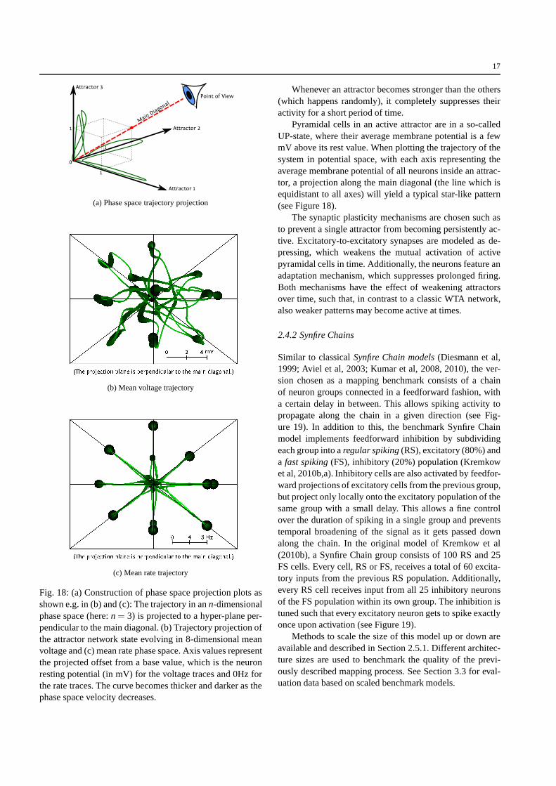
Whenever an attractor becomes stronger than the others(which happens randomly), it completely suppresses theiractivity for a short period of time.
Pyramidal cells in an active attractor are in a so-calledUP-state, where their average membrane potential is a fewmV above its rest value. When plotting the trajectory of thesystem in potential space, with each axis representing theaverage membrane potential of all neurons inside an attrac-tor, a projection along the main diagonal (the line which isequidistant to all axes) will yield a typical star-like pattern(see Figure 18).
The synaptic plasticity mechanisms are chosen such asto prevent a single attractor from becoming persistently ac-tive. Excitatory-to-excitatory synapses are modeled as de-pressing, which weakens the mutual activation of activepyramidal cells in time. Additionally, the neurons featureanadaptation mechanism, which suppresses prolonged firing.Both mechanisms have the effect of weakening attractorsover time, such that, in contrast to a classic WTA network,also weaker patterns may become active at times.
2.4.2 Synfire Chains
Similar to classicalSynfire Chain models(Diesmann et al,1999; Aviel et al, 2003; Kumar et al, 2008, 2010), the ver-sion chosen as a mapping benchmark consists of a chainof neuron groups connected in a feedforward fashion, witha certain delay in between. This allows spiking activity topropagate along the chain in a given direction (see Fig-ure 19). In addition to this, the benchmark Synfire Chainmodel implements feedforward inhibition by subdividingeach group into aregular spiking(RS), excitatory (80%) anda fast spiking(FS), inhibitory (20%) population (Kremkowet al, 2010b,a). Inhibitory cells are also activated by feedfor-ward projections of excitatory cells from the previous group,but project only locally onto the excitatory population of thesame group with a small delay. This allows a fine controlover the duration of spiking in a single group and preventstemporal broadening of the signal as it gets passed downalong the chain. In the original model of Kremkow et al(2010b), a Synfire Chain group consists of 100 RS and 25FS cells. Every cell, RS or FS, receives a total of 60 excita-tory inputs from the previous RS population. Additionally,every RS cell receives input from all 25 inhibitory neuronsof the FS population within its own group. The inhibition istuned such that every excitatory neuron gets to spike exactlyonce upon activation (see Figure 19).
Methods to scale the size of this model up or down areavailable and described in Section 2.5.1. Different architec-ture sizes are used to benchmark the quality of the previ-ously described mapping process. See Section 3.3 for eval-uation data based on scaled benchmark models.

18
+
+-
RS
FS
+
+-
RS
FS
+
+-
RS
FS
...Stimulus
Pulse Packet
Group 1 Group 2 Group n
Fig. 19: Schematic of the Synfire Chain benchmark model.
0
200
400
600
800
1000
Neu
ron
#
100 200 300 400 500 600
Time [ms]
0
200
400
600
800
1000
Neu
ron
#
Fig. 20: Raster plot of characteristic RS activity of the Syn-fire Chain without (top) and with (bottom) feedforward in-hibition. Note the constant spike packet width in case of theactive feedforward inhibition mechanism.
2.4.3 Self-Sustained AI States
Randomly connected networks of integrate-and-fire neuronsare known to display asynchronous irregular (AI) activitystates, where neurons discharge with a high level of ir-regularity, similar to stochastic processes, and with a lowlevel of synchrony (Brunel, 2000). These states were alsofound in various other network models, including those us-ing conductance-based (Vogels and Abbott, 2005) and non-linear integrate-and-fire neuron models (Destexhe, 2009).They were shown to have properties very similar to thedischarge patterns observed in awake animals (El Boustaniet al, 2007). Because cortical neurons are characterized bynonlinear intrinsic properties (Connors and Gutnick, 1990),our choice of an AI state benchmark is based on the AdExneuron model. These nonlinear IF cells are implemented inthe FACETS wafer-scale hardware (see Section 2.1.2) andreproduce several cell classes observed experimentally incortex and thalamus (see Destexhe, 2009).
The particularity of the AI benchmark model is that itallows testing the influence of the various cell classes on thegenesis of AI states by varying the different cellular proper-ties. The model considers the most prominent cell classes incerebral cortex, such as theregular spiking(RS) cell, thefastspiking(FS) cell, thelow-threshold spike(LTS) cell and theburstingcells of the thalamus. It was found that randomlyconnected networks of RS and FS cells with conductance-based synaptic interactions can sustain AI states, but only
if the adaptation currents (typical of RS cells) are not toostrong. With strong adaptation, the network cannot sustainAI states.
To the contrary, adding another cell class characterizedby rebound responses (the LTS cell) greatly enhanced therobustness of AI states, and networks as small as about 100neurons can self-sustain AI states with a proportion of 5%of LTS cells. Interestingly, if two of such networks (one withstrong adaptation, another one with LTS cells) are recipro-cally connected, the resulting 2-layer network can generatealternating periods of activity and silences. This patternisvery similar to the Up- and Down-states observed in corticalactivity during slow-wave sleep (Steriade, 2003). Reducingthe adaptation leads to sustained AI states, and is reminis-cent of the transition from sleep to wakefulness, a sort of“wakening” of the network. In the context of this paper, weuse two variants of such networks as benchmarks: First, anetwork of RS, FS and LTS cells as a minimal model of AIstates. Second, a 2-layer cortical network displaying Up andDown states. The latter is depicted in Figure 21.
...
... RS + LTS Cells
FS Cells
Cortex Layer A
Cortex Layer B
...
...RS Cells
FS Cells
...
...
...
...
Fig. 21: Schematic of the Self-Sustained AI States bench-mark model. It consists of two cortical layers A and B. Everylayer has an excitatory and an inhibitory population, each ofwhich contains certain sets of cell types (RS, FS, LTS) thatdetermine the network dynamics (see text for details). Theexcitatory populations project onto every other population,while the inhibitory populations only act within their layer.
Also this model can be scaled up and down in its sizein order to benchmark the PyNN-to-hardware mapping pro-cess. In its default version, layer A consists of 1600 excita-tory RS and 400 inhibitory FS cells. Layer B contains 400excitatory neurons, 90% of which are RS and 10% of whichare LTS type, as well as 100 inhibitory FS cells. Within asingle layer the connection probability is 2% for a networksize of 2000 cells. For smaller networks as for layer B theconnection probability is rescaled inversely to the networksize. The inter-layer connectivity is excitatory only and hasa connection probability of 1%.

19
2.5 Analysis Based on Software Simulations
Compared to pure software simulators, dedicated neuro-morphic hardware suffers more from limitations and im-perfections, which may either directly distort the morphol-ogy of the emulated network or influence its dynamics inmore subtle ways. On one hand, physical limitations such assize and number of implemented circuits or communicationbandwidth impose rather inflexible constraints on parame-ters such as number of neurons and synapses or the amountof accessible data. On the other hand, as VLSI hardwareis, inevitably, subject to manufacturing process variations,individual circuits have varying characteristics, which canonly be compensated by calibration to a certain degree. Asall these effects influence the dynamics of an emulated net-work simultaneously, it is usually very difficult to identifythe connection between an individual cause and its effect.The most straightforward solution is to artificially imposeindividual hardware-specific distortions on software simula-tions, identify their impact on the network’s dynamics andfind, if possible, suitable compensation mechanisms.
2.5.1 Network Scaling
It is very often the case that the robustness of a networkscales together with its size, or, in specific cases, with thesize or number of individual components. However, beforeanalyzing the effects of distortions, it is indispensable to de-vise a way of scaling the (undistorted) network without in-fluencing its dynamics. We have developed specific rules forscaling two of our three benchmark models, in order to bothexplore and learn how to circumvent the limitations of thehardware.
Layer 2/3 Attractor MemoryThe most obvious and natu-ral scaling of an attractor memory network lies in changingthe number of attractors, i.e. in this particular case the num-ber of minicolumns per hypercolumn. Also, the size of theattractors can be evenly scaled by changing the number ofunits per attractor, i.e. the number of hypercolumns. Finally,the size of the minicolumns itself can be scaled, by varyingthe number of neurons per column (excitatory and inhibitorypopulations can be individually tuned by changing the num-ber of pyramidal and RSNP/basket cells, respectively).
These changes would heavily affect the network dynam-ics, were they not accompanied by corresponding modifica-tions in the network connectivity. The behavior of the net-work is likely to remain unchanged if the excitation/inhi-bition patterns of each neuron are kept intact. This is mosteasily accomplished by keeping both the excitatory and theinhibitory fan-in of each neuron constant without modifyingsynaptic weights. To this end, simple scaling formulae (lin-ear with respect to size and number of the afferent popula-
tions) for the connection probabilities between populationshave been derived.
Figure 22 shows a scaling example where the numberof attractors is varied. At first glance, it may seem that the
(a) 9 HC with 3 attractors
(b) 8 HC with 20 attractors
Fig. 22: L2/3 network, scaled down to 9 hypercolumns (HC)with 3 attractors and scaled up to 8 hypercolumns with 20attractors. Note the relatively long dwell times in (a) com-pared to short dwell times in (b).
characteristic attractor dynamics are affected, as the averageattractor dwell times decrease from about 300 ms to under200 ms. However, this is only an apparent effect, as the tem-porary dominance of individual attractors is a result of localfluctuations in the input. An increasing number of attrac-tors means there is more competition among them, whichin mathematical terms translates to shorter, smaller fluctua-tions in the input rate, therefore leading to decreasing dwelltimes. When only two attractors are stimulated, the dynam-

20
ics are not influenced by the total number of attractors in thenetwork, which supports our scaling rules.
Synfire Chain with Feedforward InhibitionScaling the Syn-fire Chain is a comparatively simple task, as there are nofeedback or recurrent connections. Scaling the number ofunits does not require any changes in connectivity. Whenthe number of neurons per unit is changed, the dynamicscan be kept unmodified (synchronous firing within a popu-lation) if the number of inputs per neuron remains the same.Therefore, modifying a population size by a factorα sim-ply requires that all connection probabilities are modifiedby a factor 1/α. Some difficulties may arise when popula-tions become too small, as the binomial connection distribu-tion diverges away from a symmetric Gaussian, favoring asmaller number of afferent connections and leading to activ-ity attenuation and eventually to a break in the pulse trans-mission (Kumar et al, 2010). The straightforward remedyis offered by the PyNN classFixedNumberPreConnectorwhich guarantees a constant but randomly distributed num-ber of inputs. If populations become too small to accommo-date the required number of connections, synaptic weightscan be increased to compensate for the synaptic loss. Thesame can be done to cope with synapse loss resulting fromthe mapping process, as described in Section 3.1.1. Figure23 shows a scaling example where both size and number ofpopulations are varied.
2.5.2 Simulating Hardware Imperfections
For this study, we have investigated several distortion mech-anisms which can be replicated in software simulations anddo not require the presence of the actual hardware.
A first limitation of the hardware lies in the fact that ax-onal and dendritic delays can not be programmed and the in-trinsic delays caused by the hardware communication infra-structure are very small when translated to biological real-time. This means that, effectively, the hardware can not ac-curately reproduce the dynamics of networks which rely ondelayed transmission of action potentials between two com-municating neurons.
Two further distortion sources lie within the synapticcircuits of the HICANN building blocks. Since the synap-tic weight resolution in a neuromorphic hardware system islimited (see Section 2.1.2), large differences between synap-tic weights which are mapped to the same synapse drivermay cause significant changes to the synapses at the lowerend of the weight spectrum. Also, from our experience withthe FACETS chip-based systems (Brüderle and Müller et al,2009), we know that variations in the manufacturing processcan lead to a spatial synaptic weight jitter of up to 40% ofthe intended value (σ = 0.4µ , assuming a Gaussian distribu-tion), even after calibration. This might be fatal for networkswhich rely on precise tuning of synaptic weights.
100 200 300 400 500
Time [ms]
0
50
100
150
200
250
300
Neu
ron
#
(a) 5 populations with 64 excitatory neurons each
200 400 600 800 1000
Time [ms]
0
1000
2000
3000
4000
5000
6000
Neu
ron
#
(b) 32 populations with 200 excitatory neurons each
Fig. 23: Synfire Chain scaling examples.
Because of the limited bandwidth of the communicationlayers (see Section 2.1.3), synapses may be lost during thebiology-to-hardware mapping process. Ensuing distortionsdepend strongly on the network topology and can becomearbitrarily high for sufficiently large and densely connectednetworks.
Additionally, neuron loss can also become a key factor,not necessarily due to hardware limitations (usually, synap-tic loss becomes significant long before the number of net-work neurons exceeds the number of neurons available onthe hardware), but as an option to counteract synaptic lossby controlled reduction in the number of neurons.
Although it does not apply to the three benchmark net-works we have studied, the hardware neuron model itselfmay become a limiting factor, when trying to map modelswhich rely on more complex neurons. However, we con-sider this to be an unlikely case, as the AdEx model has beenshown to successfully reproduce a wide variety of spike pat-terns (Brette and Gerstner, 2005; Destexhe, 2009; Millneret al, 2010) and has also proven very successful in emulatingbiological spiking activity (Naud et al, 2008). This is not thecase for the FACETS chip-based neuromorphic system (seeSection 2.1.5), which only offers simple leaky integrate-and-fire neurons. Section 3.2 describes a setup where the missing

21
adaptation mechanism was compensated by tuning severalother parameters.
2.5.3 Analysis and Development of STDP in Hardware
Synaptic plasticity on the highly accelerated FACETSwafer-scale hardware (for a detailed description see Section2.1.2) provides a promising architecture for doing researchon learning. But so far there are no studies about the effectof low weight resolutions and limited update frequencieson the functionality of single synapses and consequentlyneuronal networks. In the following, two directions of studywill be outlined and one detailed example will be given.
First, the question of a required minimal resolution forsynaptic weights and their optimal update frequency is in-vestigated. However, those two restrictions may be dom-inated by production process variations that set the upperlimit for the functionality of the synapses. Production pro-cess variations cause the supposedly identical circuits forcausal and acausal correlation measurement to differ dueto variations in their transistors. This asymmetry limits theaccuracy of detecting correlations or in other words causesa correlation offset. With respect to learning neuronal net-works (e.g. Davison and Frégnac, 2006), we are especiallyinterested in the effects of hardware synapses on their abilityto detect synchronous input when embedded into an appro-priate architecture.
Secondly, the dynamics of discretized STDP are ana-lyzed based on the assumption that the weight discretiza-tion is the most crucial restricting component influencingthe dynamics of single synapses and whole networks. Thisanalysis is carried out with respect to the equilibrium weightdistribution that is obtained by evaluating an initial synapticweight value in sequence. Within this sequence of weightevolution, the probability for causal evaluation is equal tothe one for acausal evaluation. Analytical equilibrium dis-tributions (van Rossum et al, 2000) as well as numericalequilibrium distributions of continuous weights are used asa reference.
Here, we shall discuss in detail one analysis on the ef-fect of low resolution weights within a neuronal network. Inorder to isolate the functionality of a single synapse fromnetwork effects a simple network is defined (Figure 40A). Apopulation of pre-synaptic neurons is connected to a singlepost-synaptic neuron. TheIntermediate Gütig STDP model(Gütig et al, 2003; Morrison et al, 2008) is used for the con-struction of the look-up table (see Section 2.1.2). Develop-ing synaptic weights are compared for either correlated oruncorrelated pre-synaptic input. Correlation within the pre-synaptic population is generated by a multiple interactionprocess (Kuhn et al, 2003), whereas in the uncorrelated casethe firing pattern of the pre-synaptic neurons are those of
Poisson processes. Results for the effect of discrete weightson this network are presented in Section 3.2.4.
To avoid expensive changes of the chip layouts, thehardware restrictions are analyzed with preparative softwaresimulations. Therefore the standard STDP synapse modelof the software simulator NEST (Gewaltig and Diesmann,2007) was modified by introducing a causal and acausal ac-cumulation circuit, a digital weight value and global weightupdate controllers. In the following we will call this thehardware inspired model. As a reference modelanothersoftware synapse model with continuous weight values andcontinuous weight updates, but with a symmetric nearest-neighbor spike pairing scheme was implemented.
Further analysis with focus on the weight update fre-quency is in progress. In the current prototype of theHICANN building block the causal and acausal accumu-lation circuits will be reset commonly, if a weight updateis performed. Such a common reset distorts the counterbal-ancing effect of the accumulation circuit receiving less cor-relations, because the common reset suppresses the circuitto ever elicit a weight update. Consequently the dominatingaccumulation circuit, in terms of eliciting weight updates,drives all synaptic weights to its corresponding boundaryvalue. For future improvements, the performance gained byadding a second reset line to reset both accumulation circuitsindependently will be compared to the performance gain dueto a more detailed readout of these circuits. Details aboutthese additional studies will be presented in a publicationthat is in preparation.
3 Results
In the following, a summary of results is provided, allof which have been acquired by means of the workflowdescribed in Section 2. The presented data demonstratethe functionality of both the PyNN-to-hardware mappingframework and the virtual wafer-scale hardware system, asthe applied benchmark models are shown to exhibit the ex-pected functionality when processed by this environment.Examples of mapping-specific distortion analyses based onreference software simulations are provided and discussed.The effect of discretized synaptic weights, as implementedin the FACETS wafer-scale hardware, is analyzed in the con-text of an STDP benchmark. Scalability questions regard-ing the graph-based data structure for the mapping processare considered on the basis of experimental data. Further-more, we present first results of a successful application ofthe presented AdEx neuron circuit calibration scheme ac-quired with a HICANN prototype.

22
3.1 Benchmark Results
The benchmark models and their target output descriptionsdescribed in Section 2.4 represent an essential tool to testand verify the workflow presented in this article on a high,functional level. This is important especially in the contextof studies on neural network dynamics, where the identifi-cation of erroneous components from the analysis of spa-tiotemporal spike patterns can be very difficult due to a lackof insight and intuition in the field of neural information pro-cessing principles.
3.1.1 Distortion Mechanisms and Compensation StrategiesBased on Software Simulations
Even with a virtual version of the hardware system beingavailable, software simulations remain a powerful analysistool, especially since they offer access to the full range ofdynamic variables of the modeled neural network, some ofwhich may be inaccessible on the virtual hardware. In thefollowing, we will demonstrate the effects of different dis-tortion mechanisms via software simulations and proposeseveral methods to either circumvent or counteract them.These methods are chosen such as to lie within the possi-bilities of the hardware system.
Layer 2/3 Attractor MemoryThe functionality of the L2/3network is best determined by a combined analysis of spikeand voltage data. While a visual inspection of a raster plotof all neurons usually provides a good basis for evaluation,a more thorough investigation of UP/DOWN-state statisticsrequires the analysis of voltages from a relatively large num-ber of individual cells. Both the extraction of the full spikedata and of multiple voltage traces are not possible on thehardware, making the use of software simulations indispens-able for a proper evaluation of the effects of mapping distor-tions.
In order to replicate a biologically plausible pattern ofaxonal and dendritic delays, we have implemented a net-work geometry as exemplified in Figure 24, with distance-dependent delays. When setting all delays to zero, we haveobserved no significant changes in the network dynamics.This is not unexpected, as this model relies more on firingrates rather than precise spike timing in order for particularattractors to become activated.
Depending on the amount of spatial synaptic weight jit-ter, the network shows varying levels of tolerance. For val-ues up to 25%, the dynamics only suffer minor changes. At50% jitter, spontaneous activation is completely suppressed,but activation via input from L4 remains functional, exhibit-ing the same phenomena of pattern completion and rivalryas seen in the undistorted case (see Figure 25).
Fig. 24: Geometry of the L2/3 Attractor Memory model, theunit on the axes isµm.
Because of its intricate connectivity, which spans bothlocal and global scales, the Layer 2/3 Attractor Memory net-work was expected to be quite sensitive to synaptic loss. In-deed, if the synapse loss is localized to certain attractors,they become either inactive (for excitatory synapse loss) ordominant (for inhibitory synapse loss). However, if synapseloss is spread homogeneously over all populations, the net-work becomes remarkably resilient, tolerating values as highas 40% (see Figure 26).
In contrast to synaptic loss, the loss of pyramidal neu-rons (which make up about 87% of the network) has onlylittle effect on the network dynamics, even up to values ashigh as 50%, regardless of the number of minicolumns orhypercolumns present (see Figure 27). It is, for example,possible to have a functioning network with as little as 12pyramidal cells per minicolumn. This circumstance has ma-jor consequences for synapse loss compensation.
When synapse loss increases beyond a certain limit,intra-attractor excitation and inter-attractor inhibition be-come too weak for attractor dynamics to emerge. The to-tal number of synapses scales linearly with the total num-ber of neurons (when network scaling conserves the affer-ent fan-in, as described in Section 2.5.1), so reducing theneuron count represents a straightforward way of circum-venting synapse loss. This can be achieved by reducing thenumber of attractors (which may, however, not always bedesirable) or by reducing the number of neurons per attrac-tor by decreasing either the total number of hypercolumnsor the neuron count per minicolumn.
Elimination of pyramidal neurons (without re-scalingthe fan-in) is a much more efficient method in terms ofsynapse number reduction, as the total synapse count hasan approximately quadratic dependence on the number ofneurons per minicolumn. Since, for this particular network

23
(a) Spontaneous activity at 25% spatial jitter
(b) L4 activation at 50% spatial jitter
Fig. 25: Effects of spatial weight jitter on a L2/3 AttractorMemory network with 9 hypercolumns and 3 attractors.
model, attractor dynamics are largely insensitive to pyra-midal cell elimination, as described above, this becomes amethod of choice when dealing with harsh bandwidth limi-tations.
Especially in cases where synapse loss is relatively smalland inhomogeneous, afferent synaptic input can be restoredby increasing the corresponding synaptic weights (see Fig-ure 28). While it is always possible to hereby establish therequired average firing rates of individual populations, thiscompensation mechanism needs to be used cautiously, as itcan influence spike train statistics and neuron input-outputcurves.
Synfire Chain with Feedforward InhibitionThe SynfireChain model presented in Section 2.4.2 relies heavily on de-layed transmission of action potentials between inhibitoryand excitatory populations. Eliminating these delays causes
(a) Raster plot, 40% synaptic loss
(b) Voltage star plot, 40% synaptic loss
Fig. 26: Synaptic loss tolerance of an L2/3 Attractor Mem-ory network. Synaptic loss was assumed homogeneous overall populations.
Fig. 27: Attractor dwell times versus neuron loss in the L2/3Attractor Memory network.

24
(a) 60% synapse loss, uncompensated
(b) 60% synapse loss, compensation by modified weights
Fig. 28: (a) High synaptic loss destroys attractor dynamics.Several methods for compensating or counteracting this ef-fect are presented in the text above. (b) shows the results ofcompensation by modified synaptic weights.
afferent EPSPs and IPSPs to overlap, possibly leading tosuppression of efferent spikes (Kremkow et al, 2010a). Thismakes a direct mapping of the model to the FACETS wafer-scale hardware impossible. However, as the hardware offersthe possibility of tuning synaptic time constants of individ-ual neurons, it is possible to compensate for missing delaysby adjusting the rising flank of EPSPs for the inhibitory neu-rons. This can be achieved by increasing the correspondingsynaptic time constants and decreasing the correspondingsynaptic weights simultaneously (see Figure 29).
Spatial synaptic weight jitter may effectively cancel it-self out for large numbers of synapses, but can lead toskewed afferent input, especially in smaller networks. De-pending on the amount of spatial jitter (variance of the un-derlying Gaussian, see Section 2.5.2), this might lead to in-
�
�
�
�
�
���
��
���� ���� ����
�
���� ���� ����
���
���
�������
��������
��
�
�� �� ��� ��� ��� ��� ���
������� �
���� ���� ����
�!"#
$%&
(a) Synfire Chain with delayed spike propagation
�
�
�
�
�
���
��
���� ���� ����
�
���� ���� ����
���
���
�������
��������
��
�
�� �� ��� ��� ��� ��� ���
������� �
���� ���� ����
�!"#
$%&
(b) Synfire Chain with modified synapses, no delays
Fig. 29: (a) Delayed spike propagation is essential in theoriginal Synfire Chain model.(b) By modifying synaptic pa-rameters (see text for details), effective afferent spike timescan be reproduced without propagation delays.
dividual excitatory neurons not firing, as a consequence ofa too low average afferent weight. This causes a chain reac-tion which leads to an increasing number of silent neuronsfor every subsequent population in the Synfire Chain, ulti-mately causing the activity to die out (see Figure 30a).
Synapse loss has qualitatively the same effect, only man-ifests itself much stronger, as it is not symmetrically dis-tributed around zero. Even relatively low values of around2% completely suppress the propagation of the signal afteronly few iterations (see Figure 30b). Both distortion mecha-nisms can be effectively compensated by increasing exci-tatory synaptic weights (see Figure 31). Since all excita-tory neurons within a population spike only once, simultane-ously, modification of synaptic weights does not affect spiketrain statistics.
The other obvious way of compensating synapse loss isby decreasing the overall network size, as described for theL2/3 Attractor Memory network. This can be achieved bydecreasing either the number of populations or their size.Since the mapping algorithm tends to cluster neurons fromthe same population together on neighboring HICANNs, re-

25
(a) Impact of spatial weight jitter on signal propagation
(b) Impact of synapse loss on signal propagation
Fig. 30: (a) Sufficiently high spatial weight jitter causes abreakdown of signal propagation along the Synfire Chain.(b) Synapse loss is even more critical, completely attenuat-ing the signal after only few iterations.
ducing population sizes is more efficient for reducing therequired communication bandwidth.
3.1.2 Analysis Based on Virtual Hardware
The benchmark experiments were simulated with the virtualhardware, thereby verifying the functionality of the wholesoftware workflow and the general capability of the systemto serve as a neural modeling platform.
Before applying the benchmark experiments (see Sec-tion 2.4), we determined the maximum reachable bandwidthof the L2 links (FPGA-to-DNC and DNC-to-FPGA) withthe aid of the virtual hardware. We have found that – despitethe Poisson distribution of spiking activity – the achievedbandwidth corresponds to the one theoretically expectedfrom the data link speed and pulse packet sizes.
The gathered results were used to enhance the routingof L2 pulse events to the wafer (see Section 2.2.6), whichdistributes external spike sources over all available L2 links,such that the bandwidth provided by a given hardware setup
Fig. 31: Synapse loss blocks the propagation of the signalalong the synfire chain (white zone). A synapse loss prob-ability of p can be compensated very efficiently by scalingthe weights by a factor ofα/(1− p) (thick black line:α = 1,thick black line:α = 2.5). Note that the thin black line stayswithin the light gray area that denotes a stable propagationwith one spike per neuron. Increasing the synaptic weightseven more, effectively overcompensating the synapse loss,results in multiple spikes being fired by the excitatory neu-rons (dark gray and black zone). The total number of spikesper burst is limited by the refractory period and the time un-til the first inhibitory spike, meaning that the signal does notbroaden indefinitely.
is fully exploited. The application of this is crucial, whenit comes to the realization of network models with eitherhigh input rates as the Layer 2/3 attractor memory model, orhighly correlated input as for the Synfire Chain, where hun-dreds of spikes need to be delivered within a very small timewindow. Having these limitations in mind, one can choosethe size of the hardware setup properly before actually map-ping neural experiments onto the FACETS wafer-scale hard-ware, in a way that all requirements are considered in termsof spatial and temporal issues (i.e. neuron / synapse andbandwidth resources).
Synfire ChainThe Synfire Chain model with feedforwardinhibition was successfully run on the virtual FACETSwafer-scale hardware. The stable propagation of pulse vol-leys from one group to the next is plotted in Figure 32. Inthis case the network consisted of 16 groups with 100 ex-citatory and 25 inhibitory each, the groups were connectedto form a loop such that the activity would be sustained in-definitely. However, this model proved to be very sensitiveto distortions: If more than 2 neurons of a group do not fire,the Synfire Chain will die out immediately, because the lo-cal inhibition comes up too early and prevents the excita-tory cells from spiking. This happens also due to the lack of

26
synaptic delays in the current implementation of the hard-ware, as only L1 connections are used for the routing of neu-ral events within the network. For upscaled versions of thismodel and a restricted hardware size, where the mappingprocess yields a synapse loss larger than 5%, the function-ality could not be sustained according to the high sensitivityof the used parameters, i.e. the pulse volley only reachedthe second group. Nevertheless, we were able to regain thebenchmark functionality by compensating the synapse lossthrough either strengthened weights or downscaled neuronpopulations (see Section 3.1.1).
Fig. 32: Synfire Chain with 16 groups connected to a loop,simulated on the virtual hardware.
Layer 2/3 Attractor Memory ModelThe presented softwareframework also performed very well when mapping suchan elaborated neural architecture like the Layer 2/3 attrac-tor memory model onto the (virtual) FACETS wafer-scalehardware: Figure 33 shows the spike output of the defaultmodel with 2376 neurons simulated on a virtual wafer snip-pet containing 8× 2 reticles. This successful replication ofthe benchmark’s dynamics not only underscores the correctoperation of the placing and routing algorithms (see Sec-tions 2.2.5 and 2.2.6), but also indicates that the transforma-tion from biological to hardware models (see Section 2.2.7)works properly and does not distort the model’s behavior,concretely in this example a variety of different short-termplasticity settings could be transferred to shared hardwareconfigurations.
Self-Sustained AI StatesThe cortical network with self-sustaining AI states was also successfully realized on thevirtual hardware. The single-layer cortical model was im-plemented for different sizes and parameter sets, where themodel functionality was preserved without distortions. The
Fig. 33: Raster plot of the Layer 2/3 Attractor Memorymodel simulated on the virtual hardware: firing activity isshown only for pyramidal cells, default size with 9 hyper-columns and 8 attractors.
two-layer cortical network exhibiting Up and Down stateswas also realized at the default size with 2500 cells andvarying adaptation parameters, see Figure 34 for an exem-plary raster plot together with a reference software simula-tion with NEURON.
3.2 Cross-Platform Implementation of a Benchmark Model
As a demonstration of the versatility of the methodologicalframework discussed in the previous sections, this sectionwill present the implementation of one of our benchmarkmodels on three different back-ends: the software simula-tor NEST, the FACETS chip-based system and the virtualwafer-scale hardware. For this purpose, we have chosen theL2/3 Attractor Memory model, due to its challenging con-nectivity patterns and the interesting high-level functional-ity it displays. Because of the limited size of the chip back-end, the original model needed to undergo some profoundchanges, which will be detailed in the following sections.
3.2.1 FACETS Chip-Based Neuromorphic System
One ASIC in the current version of the FACETS chip-basedsystem as described in Section 2.1.5 offers 192 fully in-terconnectable leaky integrate-and-fire neurons with staticsynapses. Since the original model requires 2376 adaptingneurons interconnected through plastic synapses, we had toheavily modify the network configuration in order to keepits functionality. Reducing the total number of neurons from2376 to 192 was done following the scaling rules describedin 2.5.1. In this context, the observation that pyramidal cellscan be lost without significantly affecting the dynamics ofthe network became extremely useful. In order to provide

27
(a) NEURON
(b) Virtual Hardware
Fig. 34: Raster plot of the two-layer cortical network ex-hibiting Up and Down states simulated with NEURON (a)and on the virtual hardware (b). Horizontal lines depict thelimits between RS, FS and LTS neurons of layers A and B.The first cortical layer consists of 2000 cells, the second of500 cells. 10% of all cells are initially stimulated to induceasynchronous irregular firing in the whole network. The firstlayer is per se not self-sustaining, i.e. the activity dies outafter a while, the second smaller layer is able to sustain itsactivity due to a large number of LTS cells. The sparse con-nectivity between the two layers assures that the activity inthe first is reactivated by excitatory input from the secondlayer.
relatively long dwell times, we have chosen a setup withonly three attractors and four hypercolumns (i.e. four mini-columns per attractor). The number of basket cells per hy-percolumn was reduced from the original 8 to 6, while thenumber of pyramidal cells per hypercolumn was reducedfrom the original 30 to 12. The number of RSNP cells perminicolumn remained constant at 2. Thus, this setup imple-
ments the original model architecture with exactly 192 neu-rons. See Figure 35 for a schematic of the resulting architec-ture.
0
5
10
15
200
5
10
15
20
123456
7
8
Fig. 35: Geometry of the scaled-down L2/3 Attractor Mem-ory network model. Note the greatly reduced number of hy-percolumns (HC) and of pyramidal cells per minicolumn(MC) as compared to Figure 24.
Due to a lack of neural adaptation and synaptic plastic-ity (which are both crucial in the original model, as theylimit the pyramidal cell UP-state duration), we needed toadapt the neuron parameters (leak conductance, reset, rest,threshold and reversal potentials) and synapse characteris-tics (weight, decay time constant) in such a way as to retainas much as possible of the original dynamics, on average.One additional constraint which needed to be taken into ac-count was the limited range of synaptic weights available onthe neuromorphic chip. We were able to compensate this, tosome extent, by modifying the connection densities amongthe neuron populations.
One important consequence is that because the networkis unable to adapt, its dynamics change significantly. If onewould only remove adaptation and plasticity, without chang-ing other parameters, the first attractor which becomes acti-vated would last indefinitely. Therefore, the removal of thesetwo mechanisms needs to be accompanied by a reduction ofintra- and inter-columnar excitation. This in turn causes thenetwork to become much more input driven, which mani-fests itself in an extreme sensitivity of attractor dwell timestowards the momentary input activity. Dwell times becomemore erratic and even small changes in the average inputrate cause attractors to become either dominant or virtuallyinactive.
Also, due to the limited input bandwidth of the ASIC(for the chosen architecture: 64 channels at about 80 Hz),some degree of input correlation was inevitable, as each ofthe 144 pyramidal cells requires a Poisson stimulation of

28
300 Hz. In order to maintain attractor stability, we have cho-sen to have no overlapping inputs for different attractors(and thus zero correlation, for the Poisson input we haveused). This, on the other hand, leads to an increased inputcorrelation among pyramidal cells belonging to the same at-tractor, which, in absence of adaptation, tends to prolongattractor dwell times.
Figure 36 shows L2/3 Attractor Memory benchmark re-sults acquired with the FACETS chip-based system:
(a) Attractors have been excited by Poisson input withan overall rate of 750, 1 and 550 Hz, respectively. Note therelatively long dwell times, which are mostly due to highcorrelations among pyramidal inputs within an attractor. Thediscrepancy in the input activity needed to ensure a balancedactivation of attractors 1 and 3 is due to hardware manu-facturing fluctuations, which appear to be very complex innature, often interacting with each other and being highlydependent on the ongoing activity on the chip. (b) Attrac-tors have been excited by Poisson input with an overall rateof 750, 700 and 650 Hz, respectively. Note the large fluctua-tions in attractor dwell time due to lack of adaptation whichleads to strongly input-driven dynamics. Also note that, incontrast to Figure 36a, when attractor 2 becomes active, theinput activity of attractor 3 required an increase of 100 Hz inorder to achieve balanced activation. The most likely causeis capacitive cross-talk between the analog circuits, whichvaries depending on the throughput rate. (c) Attractors havebeen excited by Poisson input with an overall rate of 700,800 and 600 Hz, respectively. Note that only a slight in-crease of the attractor 2 input rate, with respect to the otherattractors, results in almost complete dominance of attractor2. Again, this is due to the lack of adaptive mechanisms.
3.2.2 Virtual Hardware
The scaled-down version of the L2/3 Attractor Memory net-work model was successfully implemented on thevirtualhardware(see Section 2.3). No changes had to be appliedto the model in order to realize it on the FACETS wafer-scale virtual hardware, as the HICANN building block im-plements AdEx-type neurons, which include the dynamicsof the leaky integrate-and-fire neurons from the chip-basedsystem. The scaled-down model passed through the wholemapping process described in Sections 2.2.2, 2.2.5, 2.2.6and 2.2.7 and was finally mapped and simulated on a snippetof 2×2 reticles of a wafer.
The results of the virtual hardware simulation of thescaled-down L2/3 Attractor Memory network can be seenin Figure 37, where the individual attractors were stimu-lated with different rates. Depending on the specific stim-ulation, the network reliably exhibits the same behavior asreference software simulations, which are described in thefollowing section. Figure 39 shows the 3-D visualization of
(a) Poisson input with an overall rate of 750, 1 and 550 Hz
(b) Poisson input with an overall rate of 750, 700 and 650 Hz
(c) Poisson input with an overall rate of 700, 800 and 600 Hz
Fig. 36: Raster plots of scaled-down L2/3 Attractor Memorynetworks on the FACETS chip-based neuromorphic system.For explanation see text.

29
the network model and its mapping onto the wafer with theGraViTo software (see Section 2.2.9).
3.2.3 NEST Simulator
The same PyNN script as in the previous sections was even-tually used with the software simulator NEST, as a means ofcomparison to anideal simulation environment. By provid-ing identical parameter settings, one can hereby gain a goodperspective for gauging the effects of the hardware-inherentfluctuations.
The results are practically identical to the ones from thevirtual hardware, perhaps not surprisingly, as it is not sub-ject to hardware-specific manufacturing process fluctuations(see Figures 37 and 38).
Also, due to its small size, does the network not pose anychallenge to the mapping algorithm, making the hardwarerealization a perfect replica of its software counterpart.Still,the successful emulation offers a convincing proof of theefficacy of our mapping work flow.
The chip-based neuromorphic device, on the other hand,is subject to the full range of hardware-specific distortions.Nevertheless, the resulting network dynamics agree wellwith the NEST results, requiring only small adjustmentsin the input activity. These results are expected to greatlyimprove on the wafer-scale hardware, thanks to the supe-rior architecture of the HICANN units. Also, a much morecomplex neuron model and the availability of both short-and long-term synaptic plasticity mechanisms will make thewafer-scale hardware much more capable of emulating bio-logically accurate network models.
As a conclusion, we note that the software results are invery good agreement with the ones generated by our hard-ware back-ends, thus supporting our work flow concept andsolidifying the position of our neuromorphic hardware as auniversal modeling tool. The particularly appealing feature,especially from a neural modeling perspective, is the seam-less transition from software simulation to hardware emula-tion, which, from the perspective of the PyNN user, is ac-complished by modifying a single line of code.
3.2.4 Analysis and Development of STDP in Hardware
The effects of discrete synaptic weights on networks is ana-lyzed by means of a simple network (Figure 40A). Ten pre-synaptic neurons are connected to one post-synaptic neuronusing both the reference and the hardware inspired STDPsynapses as described in Section 2.5.3. In order to analyzeeffects of discrete weights isolated from other hardware spe-cific constraints the weight update frequency is set equal tothe time resolutionh= 0.1ms of the software simulator. Thespike rates of the pre-synaptic neurons are adapted in suchway that the post-synaptic neuron is firing at about 10Hz.
(a) Poisson input with overall rate of 550, 1 and 550 Hz
(b) Poisson input with overall rate of 700 Hz
(c) Poisson input with overall rate of 700, 800 and 700 Hz
Fig. 37: Scaled-down L2/3 Attractor Memory network simu-lated with thevirtual hardware. Attractors have been excitedby Poisson input with different overall rates.

30
(a) Poisson input with overall rate of 550, 1 and 550 Hz
(b) Poisson input with overall rate of 700 Hz
(c) Poisson input with overall rate of 700, 800 and 700 Hz
Fig. 38: Scaled-down L2/3 Attractor Memory network sim-ulated with the NEST software. Attractors have been excitedby Poisson input with different overall rates.
Fig. 39: 3-D view of the scaled-down L2/3 Attractor Mem-ory network model (see Figure 35) and its mapping to thewafer generated by the GraViTo software (Section 2.2.9).
In case of correlated pre-synaptic neurons their correlationcoefficient isc = 0.05 (Kuhn et al, 2003). Varying the in-put spike rates or the correlation coefficient does not changethe conceptual outcome. As the currently implemented hard-ware synapses have a weight resolution of 4 bits, this reso-lution is used to test the performance of the hardware.
Figure 40 shows the mean weight traces for runs withcorrelated pre-synaptic neurons as well as for separate runswith uncorrelated pre-synaptic neurons. In case of hardwareinspired STDP synapses (Figure 40C) the standard devia-tions of the mean weight traces are much larger than thoseof the reference STDP synapses. These increased deviationsare due to the large weight steps between adjacent discreteweights. Applying a t-test to the synaptic weight distribu-tion after 1000s shows that the hardware inspired STDPsynapses can nevertheless distinguish between uncorrelatedand correlated input. For hardware inspired STDP synapsesthe probability that the synaptic weights of both populationsare separated isp = 0.02, compared top= 2 ·10−8 for thereference STDP synapses. This ability of distinction deter-mines the ability of detecting synchronous input, which isfundamental for most STDP applications. For correlationcoefficients as low asc = 0.05 a resolution of 4 bits is stillsufficient to detect synchronous pre-synaptic firing.
3.3 Software Performance
The usability of any hardware modeling platform stronglydepends on the time needed for configuration and repro-gramming, thus the benchmarks introduced in Section 2.4also serve as tests forscalabilityin terms of time and space.
Figure 41 shows that the space consumption for theBio-Modeldata grows almost linearly depending on the numberof neurons and the synaptic densityρSyn. Thus, for the givenbenchmarks, the model sizes for networks with a neuroncountNBIO ≤ 105 and an approximate averageρSyn≤ 10%stay within an acceptable limit of 10 GByte. Furthermore,

31
0 250 500 750 1000Time [s]
0.0
0.2
0.4
0.6
0.8
1.0
w
0 250 500 750 1000Time [s]
0.0
0.2
0.4
0.6
0.8
1.0
Reference Hardware Inspired
0.0
0.2
0.4
0.6
0.8
1.0 *** *A B C D
Fig. 40: A STDP evaluation network layout with variable correlation strengthc. Gray circles represent neurons, arrowssynapses. The spike trains of neurons contain random (black) and correlated (red) spikes.B Mean (thick line) and standarddeviation (shaded area) of reference STDP synapses with correlated (green) and uncorrelated (blue) pre-synaptic neurons.Thin lines are single example traces.C Like B, but with hardware inspired STDP synapses.D Weight distributions after1000s for reference (p< 0.001) and hardware inspired (p< 0.05) STDP synapses.
the placement algorithms, in spite of the cubical problem,grow belowO(n2) and as such fulfill the requirement of areasonable runtime for complex mapping problems (Ehrlichet al, 2010).
0
1 00
200
300
400
500
600
700
800
1 03 1 04
Number of Neurons
Mo
del
Siz
e [M
Byt
e]
Synfire ChainL2/3 Attractor
Self-Sustained AI
Fig. 41: Mapping process scaling in terms ofBioModelsizes(Ehrlich et al, 2010).
3.4 HICANN Prototype Calibration
In order to provide an example of its functionality, the cali-bration framework described in Section 2.2.7 has been usedto reproduce a biologically relevant tonic spiking neuron onthe HICANN prototype. First, a reference simulation of atonic spiking neuron using the AdEx model was created.For this simulation, the adaptation and exponential termswere disabled. The simulated neuron showed a firing rateof 53.4Hz, which due to the speedup factor of the HICANNsystem corresponds to 534kHz in the hardware domain.
The calibration was performed on a hardware neuron,and the calibration data was stored in the database. Then, thebiological parameters from the reference simulation weresent to the database, which provided the necessary hardwareparameters in return. The floating gates of the correspondingneuron on the HICANN prototype were then programmedwith these values. The results are shown in Figure 42. After
0 5 10 15 20
Time [us]
600
700
800
900
Mem
bra
ne P
ote
nti
al
[mV
]
(a) Reference simulation
0 5 10 15 20
Time [us]
600
700
800
900
Mem
bra
ne P
ote
nti
al
[mV
]
(b) Hardware neuron recording
Fig. 42: Comparison between the reference simulation (a)and the membrane recording of the hardware neuron aftercalibration (b).

32
calibration, the hardware neuron showed a firing rate of 536kHz, which is very close to the reference simulation.
4 Discussion
Within the FACETS research project, a novel type of neu-romorphic hardware system has been developed. The de-vice combines massive acceleration, large network sizes anda high configurability with the possible advantages inher-ent to analog designs, such as power efficiency and a time-continuous operation. Following this strategy, neuromorphicengineering has the potential to step out of its niche and pro-vide new and relevant input to neuroscience, e.g. towards theunderstanding of cortical dynamics. Still, as we noticed dur-ing the development of the system and during first exper-iments with prototypes, the originally available techniquesand tools were clearly insufficient for exploiting the poten-tial of such devices in a modeling context. It is our experi-ence that the quality of interfaces that make hardware flex-ibility actually usable is as essential as the electronic sub-strate itself.
The presented work approaches this challenge by intro-ducing a methodological framework that establishes a bal-ance between the configuration complexity and potentialof a novel hardware system on the one hand and the us-ability and spectrum of possible applications for modelerswithout a hardware background on the other. This neuro-morphic modeling workflow has been depicted both in itsconceptual whole and by means of detailed component de-scriptions. It represents one major outcome of the inter-disciplinary collaboration among FACETS partners, therebyintegrating expertise and progress in the fields of physio-logically well-founded cortex modeling, hardware engineer-ing and community-driven software development. The mul-titude of the described components and their structured in-teraction reflects the comprehensiveness we are aiming at.
We showed experimental data that provide a proof ofmature functionality of the implemented stack of model-to-hardware translation tools. The experimental results ofmapping distortion studies on the basis of our virtual wafer-scale hardware system and reference software simulationsrepresent examples of ongoing analysis work that continu-ously improves our software layer stack, the hardware de-sign and our neuromorphic modeling experience. A dedi-cated follow-up publication focusing on these analysis ef-forts and implications of the corresponding results is inpreparation.
For the close future we also plan to extend the set ofmodels that we use to benchmark and tune our workflow. Sofar the realization of a large variety of biologically relevantstructures has been the primary goal of iteratively applyingthe depicted optimization process. A second focus will beput on computationally powerful architectures in general,
independent of their biological plausibility. Building uponthis work, the presented methodological framework with theneuromorphic hardware system at its core will eventually beused to approach open neuroscientific questions.
Acknowledgements The research leading to these results has re-ceived funding by the Sixth Framework Programme of the EuropeanCommunity (EC) under grant agreement no. 15879 (FACETS). Marc-Olivier Schwartz is supported by a doctoral fellowship in the SeventhFramework Programme of the EC under grant agreement no. 237955(FACETS-ITN). Lyle Muller is supported by a doctoral fellowshipfrom the École des Neurosciences de Paris (ENP, Paris Schoolof Neu-roscience).
References
Aviel Y, Mehring C, Abeles M, Horn D (2003) On embed-ding synfire chains in a balanced network. Neural Com-putation 15(6):1321–1340
Berge HKO, Häfliger P (2007) High-speed serial AER onFPGA. In: Proceedings of the 2007 IEEE InternationalSymposium on Circuits and Systems (ISCAS), pp 857–860
Bill J, Schuch K, Brüderle D, Schemmel J, Maass W,Meier K (2010) Compensating inhomogeneities of neuro-morphic VLSI devices via short-term synaptic plasticity.Front Comp Neurosci 4(129)
Binzegger T, Douglas RJ, Martin KAC (2004) A quantita-tive map of the circuit of cat primary visual cortex. J Neu-rosci 24(39):8441–53
Bontorin G, Renaud S, Garenne A, Alvado L, Le MassonG, Tomas J (2007) A real-time closed-loop setup for hy-brid neural networks. In: Proceedings of the 29th An-nual International Conference of the IEEE Engineeringin Medicine and Biology Society (EMBS2007)
BrainScaleS (2010) Project website.http://www.brainscales.eu
Brette R, Gerstner W (2005) Adaptive exponential integrate-and-fire model as an effective description of neuronal ac-tivity. J Neurophysiol 94:3637 – 3642
Brette R, Rudolph M, Carnevale T, Hines M, Beeman D,Bower JM, Diesmann M, Morrison A, Goodman PH, Har-ris Jr FC, Zirpe M, Natschlager T, Pecevski D, ErmentroutB, Djurfeldt M, Lansner A, Rochel O, Vieville T, MullerE, Davison AP, El Boustani S, Destexhe A (2006) Simu-lation of networks of spiking neurons: A review of toolsand strategies. Journal of Computational Neuroscience3(23):349–98
Brüderle D (2009) Neuroscientific modeling with a mixed-signal VLSI hardware system. PhD thesis, Ruprecht-Karls-Universität Heidelberg
Brüderle D, Müller E, Davison A, Muller E, Schemmel J,Meier K (2009) Establishing a novel modeling tool: A

33
python-based interface for a neuromorphic hardware sys-tem. Front Neuroinform 3(17)
Brüderle D, Bill J, Kaplan B, Kremkow J, Meier K, MüllerE, Schemmel J (2010) Simulator-like exploration of cor-tical network architectures with a mixed-signal VLSI sys-tem. In: Proceedings of the 2010 IEEE International Sym-posium on Circuits and Systems (ISCAS), pp 2784–2787
Brunel N (2000) Dynamics of sparsely connected networksof excitatory and inhibitory spiking neurons. Journal ofComputational Neuroscience 8(3):183–208
Burkitt A, Gilson M, Hemmen J (2007) Spike-timing-dependent plasticity for neurons with recurrent connec-tions. Biological Cybernetics 96(5):533–546
Buxhoeveden D, Casanova M (2002) The minicolumn andevolution of the brain. Brain Behav Evol 60:125–151
Connors B, Gutnick M (1990) Intrinsic firing patterns of di-verse neocortical neurons. Trends Neurosci 13:99–104
Costas-Santos J, Serrano-Gotarredona T, Serrano-Gotarredona R, Linares-Barranco B (2007) A spatialcontrast retina with on-chip calibration for neuromorphicspike-based AER vision systems. IEEE Transactions onCircuits and Systems 54(7):1444–1458
Dante V, Del Giudice P, Whatley A (2005) Hardware andsoftware for interfacing to address-event based neuromor-phic systems. The Neuromorphic Engineer 2(1):5–6
Davison AP, Frégnac Y (2006) Learning crossmodal spatialtransformations through spike-timing-dependent plastic-ity. The Journal of Neuroscience 26(21):5604–5615
Davison AP, Brüderle D, Eppler JM, Kremkow J, Muller E,Pecevski D, Perrinet L, Yger P (2008) PyNN: a commoninterface for neuronal network simulators. Front Neuroin-form 2(11)
Delbrück T, Liu SC (2004) A silicon early visual system asa model animal. Vision Res 44(17):2083–2089
Destexhe A (2009) Self-sustained asynchronous irregularstates and Up/Down states in thalamic, cortical and thala-mocortical networks of nonlinear integrate-and-fire neu-rons. Journal of Computational Neuroscience 3:493–506
Destexhe A, Contreras D, Steriade M (1998) Mechanismsunderlying the synchronizing action of corticothalamicfeedback through inhibition of thalamic relay cells. Jour-nal of Neurophysiology 79:999–1016
Diesmann M, Gewaltig MO, Aertsen A (1999) Stable propa-gation of synchronous spiking in cortical neural networks.Nature 402:529–533
Douglas RJ, Martin KAC (2004) Neuronal circuits of theneocortex. Annu Rev Neurosci 27:419–51
Ehrlich M, Mayr C, Eisenreich H, Henker S, Srowig A,Grübl A, Schemmel J, Schüffny R (2007) Wafer-scaleVLSI implementations of pulse coupled neural networks.In: Proceedings of the International Conference on Sen-sors, Circuits and Instrumentation Systems (SSD-07)
Ehrlich M, Wendt K, Zühl L, Schüffny R, Brüderle D,Müller E, Vogginger B (2010) A software framework formapping neural networks to a wafer-scale neuromorphichardware system. In: Proceedings of ANNIIP 2010, pp43–52
El Boustani S, Pospischil M, Rudolph-Lilith M, DestexheA (2007) Activated cortical states: experiments, analysesand models. Journal of Physiology (Paris) 101:99–109
Eppler JM, Helias M, Muller E, Diesmann M, Gewaltig MO(2008) PyNEST: a convenient interface to the NEST sim-ulator. Front Neuroinform 2(12)
FACETS (2010) Fast Analog Computing with Emer-gent Transient States – Project website.http://www.
facets-project.org
Fairhurst G (2002) RFC 3366: Advice to link designers onlink Automatic Repeat reQuest (ARQ). URLhttp://www.rfc-editor.org/rfc/rfc3366.txt
Fieres J, Schemmel J, Meier K (2008) Realizing biologi-cal spiking network models in a configurable wafer-scalehardware system. In: Proceedings of the 2008 Interna-tional Joint Conference on Neural Networks (IJCNN)
Friedmann S (2009) Extending a hardware neural net-work beyond chip boundaries. Diploma thesis (En-glish), Ruprecht-Karls-Universität, Heidelberg, HD-KIP-09-41, URL http://www.kip.uni-heidelberg.de/
Veroeffentlichungen/details.php?id=1938
Fu Z, Culurciello E, Lichtsteiner P, Delbrück T (2008) Falldetection using an address-event temporal contrast visionsensor. In: Proceedings of the 2008 IEEE InternationalSymposium on Circuits and Systems (ISCAS), pp 424–427
Gewaltig MO, Diesmann M (2007) NEST (NEural Simula-tion Tool). Scholarpedia 2(4):1430
Gomez-Rodriguez F, Miro-Amarante L, Diaz-del Rio F,Linares-Barranco A, Jimenez G (2010) Real time mul-tiple objects tracking based on a bio-inspired processingcascade architecture. In: Proceedings of 2010 IEEE Inter-national Symposium on Circuits and Systems (ISCAS),pp 1399–1402
Goodman D, Brette R (2008) Brian: a simulator for spikingneural networks in Python. Front Neuroinform 2(5)
Gütig R, Aharonov R, Rotter S, Sompolinsky H (2003)Learning input correlations through nonlinear temporallyasymmetric hebbian plasticity. J Neurosci 23(9):3697–3714
Häfliger P (2007) Adaptive WTA with an analog VLSI neu-romorphic learning chip. IEEE Transactions on NeuralNetworks 18(2):551–72
Hartmann S, Schiefer S, Scholze S, Partzsch J, MayrC, Henker S, Schüffny R (2010) Highly integratedFPGA board for packet-based AER communication with3GEvents/s throughput. In: Proceedings of the 2010 IEEEInternational Conference on Electronics, Circuits and

34
Systems (ICECS), acceptedHines ML, Carnevale NT (2006) The NEURON Book.
Cambridge University Press, Cambridge, UKHines ML, Davison AP, Muller E (2009) NEURON and
Python. Front Neuroinform 3(1)Horak R (2007) Telecommunications and data communica-
tions handbook. Wiley-InterscienceHunter JD (2007) Matplotlib: A 2D graphics environment.
IEEE Computing in Science and Engineering 9(3):90–95Indiveri G (2008) Neuromorphic VLSI models of selective
attention: From single chip vision sensors to multi-chipsystems. Sensors 8(9):5352–5375
Indiveri G, Chicca E, Douglas R (2006) A VLSI array oflow-power spiking neurons and bistable synapses withspike-timing dependent plasticity. IEEE Transactions onNeural Networks 17(1):211–221
Indiveri G, Chicca E, Douglas R (2009) Artificial cognitivesystems: From VLSI networks of spiking neurons to neu-romorphic cognition. Cognitive Computation 1(2):119–127
Jeltsch S (2010) Computing with transient states on a neu-romorphic multi-chip environment. Diploma thesis (En-glish), Ruprecht-Karls-Universität, Heidelberg, HD-KIP10-54, URL http://www.kip.uni-heidelberg.de/
Veroeffentlichungen/details.php?id=2095
Jones E, Oliphant T, Peterson P (2001) SciPy: Open sourcescientific tools for Python. URLhttp://www.scipy.org/
Kaplan B, Brüderle D, Schemmel J, Meier K (2009) High-conductance states on a neuromorphic hardware system.In: Proceedings of the 2009 International Joint Confer-ence on Neural Networks (IJCNN)
Kremkow J, Kumar A, Rotter S, Aertsen A (2007) Emer-gence of population synchrony in a layered network ofthe cat visual cortex. Neurocomputing 70:2069 – 2073
Kremkow J, Aertsen A, Kumar A (2010a) Gating of signalpropagation in spiking neural networks by balanced andcorrelated excitation and inhibition. J Neurosci, in press
Kremkow J, Perrinet L, Masson G, Aertsen A (2010b)Functional consequences of correlated excitatory and in-hibitory conductances. J Comput Neurosci 28 (3):579–594
Kuhn A, Aertsen A, Rotter S (2003) Higher-order statisticsof input ensembles and the response of simple model neu-rons. Neural Computation 15(1):67–101
Kumar A, Rotter S, Aertsen A (2008) Conditions for propa-gating synchronous spiking and asynchronous firing ratesin a cortical network model. J Neurosci 28(20):5268–80
Kumar A, Rotter S, Aertsen A (2010) Spiking activity prop-agation in neuronal networks: reconciling different per-spectives on neural coding. Nat Rev Neurosci 11(9):615–627
Lande T, Ranjbar H, Ismail M, Berg Y (1996) An analogfloating-gate memory in a standard digital technology. In:Microelectronics for Neural Networks, 1996., Proceed-ings of Fifth International Conference on, pp 271 –276
Langtangen HP (2008) Python Scripting for ComputationalScience, 3rd edn. Springer
Lewis MA, Etienne-Cummings R, Cohen AH, Hartmann M(2000) Toward biomorphic control using custom aVLSIchips. In: Proceedings of the International conference onrobotics and automation, IEEE Press
Lundqvist M, Rehn M, Djurfeldt M, Lansner A (2006) At-tractor dynamics in a modular network of neocortex. Net-work:Computation in Neural Systems 17:3:253–276
Lundqvist M, Compte A, Lansner A (2010) Bistable, irreg-ular firing and population oscillations in a modular attrac-tor memory network. PLoS Comput Biol 6(6)
Markram H, Toledo-Rodriguez M, Wang Y, Gupta A, Sil-berberg G, Wu C (2004) Interneurons of the neocorticalinhibitory system. Nat Rev Neurosci 5(10):793–807
Mead CA (1989) Analog VLSI and Neural Systems. Addi-son Wesley, Reading, MA
Mead CA (1990) Neuromorphic electronic systems. Pro-ceedings of the IEEE 78:1629–1636
Mead CA, Mahowald MA (1988) A silicon model of earlyvisual processing. Neural Networks 1(1):91–97
Merolla PA, Boahen K (2006) Dynamic computation in arecurrent network of heterogeneous silicon neurons. In:Proceedings of the 2006 IEEE International Symposiumon Circuits and Systems (ISCAS)
Millner S, Grübl A, Schemmel J, Meier K, Schwartz MO(2010) A VLSI implementation of the adaptive exponen-tial integrate-and-fire neuron model. In: Advances in Neu-ral Information Processing Systems (NIPS), accepted
Mitra S, Fusi S, Indiveri G (2009) Real-time classificationof complex patterns using spike-based learning in neu-romorphic VLSI. IEEE Transactions on Biomedical Cir-cuits and Systems 3:(1):32–42
Morrison A, Mehring C, Geisel T, Aertsen A, DiesmannM (2005) Advancing the boundaries of high connectiv-ity network simulation with distributed computing. Neu-ral Comput 17(8):1776–1801
Morrison A, Aertsen A, Diesmann M (2007) Spike-Timing-Dependent Plasticity in Balanced Random Networks.Neural Comp 19(6):1437–1467
Morrison A, Diesmann M, Gerstner W (2008) Phenomeno-logical models of synaptic plasticity based on spike tim-ing. Biological Cybernetics 98(6):459–478
Mountcastle VB (1997) The columnar organization of theneocortex. Brain 120(4):701–722
Naud R, Marcille N, Clopath C, Gerstner W (2008) Fir-ing patterns in the adaptive exponential integrate-and-firemodel. Biological Cybernetics 99(4):335–347

35
Netter T, Franceschini N (2002) A robotic aircraft that fol-lows terrain using a neuromorphic eye. In: Conf. Intelli-gent Robots and System, pp 129–134
NeuroTools (2008) Website.http://neuralensemble.org/trac/NeuroTools
Norris M (2003) Gigabit Ethernet Technology and Applica-tions. Artech House, Boston
Oliphant TE (2007) Python for scientific computing. IEEEComputing in Science and Engineering 9(3):10–20
Oster M, Whatley AM, Liu SC, Douglas RJ (2005) A hard-ware/software framework for real-time spiking systems.In: Proceedings of the 2005 International Conference onArtificial Neural Networks (ICANN)
Pecevski DA, Natschläger T, Schuch KN (2009) PCSIM: Aparallel simulation environment for neural circuits fullyintegrated with Python. Front Neuroinform 3(11)
Philipp S, Schemmel J, Meier K (2009) A QoS networkarchitecture to interconnect large-scale VLSI neural net-works. In: Proceedings of the 2009 International JointConference on Neural Networks (IJCNN), pp 2525 –2532
Pospischil M, Toledo-Rodriguez M, Monier C, PiwkowskaZ, Bal T, Frégnac Y, Markram H, Destexhe A (2008)Minimal hodgkin-huxley type models for different classesof cortical and thalamic neurons. Biological Cybernetics99(4):427–441
Renaud S, Tomas J, Bornat Y, Daouzli A, Saighi S (2007)Neuromimetic ICs with analog cores: an alternative forsimulating spiking neural networks. In: Proceedings ofthe 2007 IEEE Symposium on Circuits and Systems (IS-CAS)
van Rossum, Bi GQ, Turrigiano G (2000) Stable hebbianlearning from spike timing-dependent plasticity. J Neu-rosci 20:8812–21
Schemmel J, Meier K, Muller E (2004) A new VLSI modelof neural microcircuits including spike time dependentplasticity. In: Proceedings of the 2004 International JointConference on Neural Networks (IJCNN), IEEE Press, pp1711–1716
Schemmel J, Grübl A, Meier K, Muller E (2006) Imple-menting synaptic plasticity in a VLSI spiking neural net-work model. In: Proceedings of the 2006 InternationalJoint Conference on Neural Networks (IJCNN), IEEEPress
Schemmel J, Brüderle D, Meier K, Ostendorf B (2007)Modeling synaptic plasticity within networks of highlyaccelerated I&F neurons. In: Proceedings of the 2007IEEE International Symposium on Circuits and Systems(ISCAS), IEEE Press, pp 3367–3370
Schemmel J, Fieres J, Meier K (2008) Wafer-scale integra-tion of analog neural networks. In: Proceedings of the2008 International Joint Conference on Neural Networks(IJCNN)
Schemmel J, Brüderle D, Grübl A, Hock M, Meier K, Mill-ner S (2010) A wafer-scale neuromorphic hardware sys-tem for large-scale neural modeling. In: Proceedings ofthe 2010 IEEE International Symposium on CircuitsandSystems (ISCAS), pp 1947–1950
Schilling M (2010) A highly efficient transport layer for theconnection of neuromorphic hardware systems. Diplomathesis, Ruprecht-Karls-Universität Heidelberg, HD-KIP-10-09, URL http://www.kip.uni-heidelberg.de/
Veroeffentlichungen/details.php?id=2000
Scholze S, Henker S, Partzsch J, Mayr C, Schüffny R (2010)Optimized queue based communication in VLSI using aweakly ordered binary heap. In: Proceedings of the 2010International Conference on Mixed Design of IntegratedCircuits and Systems (MIXDES)
Serrano-Gotarredona R, Oster M, Lichtsteiner P, Linares-Barranco A, Paz-Vicente R, Gómez-Rodríguez F, RiisHK, Delbrück T, Liu SC, Zahnd S, Whatley AM, Dou-glas RJ, Häfliger P, Jimenez-Moreno G, Civit A, Serrano-Gotarredona T, Acosta-Jiménez A, Linares-Barranco B(2006) AER building blocks for multi-layer multi-chipneuromorphic vision systems. In: Weiss Y, Schölkopf B,Platt J (eds) Advances in Neural Information ProcessingSystems 18, MIT Press, Cambridge, MA, pp 1217–1224
Steriade M (2003) Neuronal Substrates of Sleep andEpilepsy. Cambridge University Press, Cambridge, UK
Tao L, Shelley M, McLaughlin D, Shapley R (2004) Anegalitarian network model for the emergence of simpleand complex cells in visual cortex. PNAS 101:366–371
Vogels TP, Abbott LF (2005) Signal propagation and logicgating in networks of integrate-and-fire neurons. J Neu-rosci 25(46):10,786–95
Vogelstein RJ, Mallik U, Vogelstein JT, CauwenberghsG (2007) Dynamically reconfigurable silicon array ofspiking neuron with conductance-based synapses. IEEETransactions on Neural Networks 18:253–265
Vogginger B (2010) Testing the operation workflow of aneuromorphic hardware system with a functionally accu-rate model. Diploma thesis, Ruprecht-Karls-UniversitätHeidelberg, HD-KIP-10-12, URLhttp://www.kip.uni-heidelberg.de/Veroeffentlichungen/
details.php?id=2003
Wendt K, Ehrlich M, Schüffny R (2008) A graph theoret-ical approach for a multistep mapping software for theFACETS project. In: Proceedings of the 2008 WSEASInternational Conference on Computer Engineering andApplications (CEA), pp 189–194
Wendt K, Ehrlich M, Schüffny R (2010) GMPath - a pathlanguage for navigation, information query and modifica-tion of data graphs. In: Proceedings of ANNIIP 2010, pp31 – 42
Zucker RS, Regehr WG (2002) Short-term synaptic plastic-ity. Annu Rev Physiol 64:355–405
Related Documents