Submitted after revision to the Journal of Systems and Software A Comprehensive Engineering Framework for Guaranteeing Component Compatibility J. Floch 1,* , C. Carrez 1,2 , P. Cieślak 3 , M. Rój 3 , R. T. Sanders 1 , M. M. Shiaa 4 1 SINTEF ICT, NO-7465 Trondheim, Norway 2 Norwegian University of Science and Technology, NO-7491 Trondheim, Norway 3 Institute of Telecommunications, Warsaw University of Technology, Warsaw, Poland 4 Gintel, NO-7465 Trondheim, Norway * Corresponding Author: [email protected] ABSTRACT Despite advances in software engineering methods and tools, understanding what software components do and ensuring that they work well together remains difficult. This is chiefly due to the lack of support for specifying component interfaces and software compositions formally. Due to these shortcomings, composed systems are subject to incompatibility errors, and software developers struggle to retrieve and understand relevant reusable entities. Constructs recently added to the Unified Modeling Language (UML) supported by validation tools can detect and solve behavioural incompatibility issues, while integrated support for characterisation using ontological techniques can describe what a component does. This paper presents a comprehensive software engineering framework that supports software composition at design time and runtime with compatibility guarantees. Our main contributions are (a) a model-driven development approach that combines UML modelling and ontology techniques for the specification of component properties, their validation and their transformation to code, (b) a middleware platform that supports component discovery, compatibility checking and deployment. Following the proposed approach gives benefits for software engineering, in particular in settings where multiple stakeholders are involved. KEY WORDS Software composition, semantic interfaces, model-driven development, UML, ontology techniques, validation, dynamic discovery, software deployment. 1 Introduction One of the core challenges of component-based software engineering is to find practical ways to model components independently of each other, so that components can be composed into well functioning systems. Software composition in general involves static composition at design time as well as dynamic discovery and binding at runtime. Although many ideas introduced by architecture definition languages [1] were adopted by UML 2 [2], engineering methods and tools still lack support for specifying component interfaces and software compositions formally. UML is a widely recognized and used modelling standard, and therefore offers a promising basis for the modelling and validation of component-based software. The UML 2 collaboration concept does indeed provide a structured way to define partial functionalities in terms of collaborating roles. It allows system parts to be modelled as collaboration roles and interface behaviour to be specified using interactions, activity diagrams and state machines as explained in [3,4,5,6]. Moreover it provides means to compose and decompose systems and to bind collaboration roles to classifiers that define system components. In this way, UML collaborations directly support modelling and composition at design time. Beyond modelling, collaborations also enable composed software systems to be analysed for errors so that correctness can be ensured at a very early stage. Implementations and other models needed at runtime may subsequently be automatically generated for a range of different platforms. Another challenge of component-based software engineering is to provide better tools for developers and users to retrieve and reuse components. When the number of components becomes large, one needs to devise techniques to characterize components that ease the burden of searching and selecting. Interfaces and components are usually described informally, making the search after components that support a set of desired functionalities cumbersome. Models in UML or other formal languages might facilitate understanding, but still retrieving components and grasping their meanings based on detailed

Welcome message from author
This document is posted to help you gain knowledge. Please leave a comment to let me know what you think about it! Share it to your friends and learn new things together.
Transcript
Submitted after revision to the Journal of Systems and Software
A Comprehensive Engineering Framework for Guaranteeing Component Compatibility
J. Floch1,*, C. Carrez1,2, P. Cieślak3, M. Rój3, R. T. Sanders1, M. M. Shiaa4
1 SINTEF ICT, NO-7465 Trondheim, Norway 2 Norwegian University of Science and Technology, NO-7491 Trondheim, Norway 3 Institute of Telecommunications, Warsaw University of Technology, Warsaw, Poland 4 Gintel, NO-7465 Trondheim, Norway * Corresponding Author: [email protected]
ABSTRACT
Despite advances in software engineering methods and tools, understanding what software components do and ensuring that they work well together remains difficult. This is chiefly due to the lack of support for specifying component interfaces and software compositions formally. Due to these shortcomings, composed systems are subject to incompatibility errors, and software developers struggle to retrieve and understand relevant reusable entities. Constructs recently added to the Unified Modeling Language (UML) supported by validation tools can detect and solve behavioural incompatibility issues, while integrated support for characterisation using ontological techniques can describe what a component does. This paper presents a comprehensive software engineering framework that supports software composition at design time and runtime with compatibility guarantees. Our main contributions are (a) a model-driven development approach that combines UML modelling and ontology techniques for the specification of component properties, their validation and their transformation to code, (b) a middleware platform that supports component discovery, compatibility checking and deployment. Following the proposed approach gives benefits for software engineering, in particular in settings where multiple stakeholders are involved.
KEY WORDS
Software composition, semantic interfaces, model-driven development, UML, ontology techniques, validation, dynamic discovery, software deployment.
1 Introduction
One of the core challenges of component-based software engineering is to find practical ways to model components independently of each other, so that components can be composed into well functioning systems. Software composition in general involves static composition at design time as well as dynamic discovery and binding at runtime. Although many ideas introduced by architecture definition languages [1] were adopted by UML 2 [2], engineering methods and tools still lack support for specifying component interfaces and software compositions formally. UML is a widely recognized and used modelling standard, and therefore offers a promising basis for the modelling and validation of component-based software. The UML 2 collaboration concept does indeed provide a structured way to define partial functionalities in terms of collaborating roles. It allows system parts to be modelled as collaboration roles and interface behaviour to be specified using interactions, activity diagrams and state machines as explained in [3,4,5,6]. Moreover it provides means to compose and decompose systems and to bind collaboration roles to classifiers that define system components. In this way, UML collaborations directly support modelling and composition at design time. Beyond modelling, collaborations also enable composed software systems to be analysed for errors so that correctness can be ensured at a very early stage. Implementations and other models needed at runtime may subsequently be automatically generated for a range of different platforms.
Another challenge of component-based software engineering is to provide better tools for developers and users to retrieve and reuse components. When the number of components becomes large, one needs to devise techniques to characterize components that ease the burden of searching and selecting. Interfaces and components are usually described informally, making the search after components that support a set of desired functionalities cumbersome. Models in UML or other formal languages might facilitate understanding, but still retrieving components and grasping their meanings based on detailed
Submitted after revision to the Journal of Systems and Software
2
behavioural models is not easy. A promising solution is to make use of ontologies. Ontology-based techniques provide a means to describe and reason on the purpose of software entities, and is complementary with the description of detailed behaviours specified using UML [7,8].
In this paper we present the results of SIMS, a joint European research project with seven partners from industry and academia [9]. SIMS has addressed software composition and validation from both the theoretical and practical perspectives. It proposes a comprehensive software engineering framework that combines the UML and ontology-based techniques in order to support the engineering of component-based software and ensure compatibility guarantees in open development and runtime environments. UML is used to ensure behavioural compatibility between software components, i.e. the correctness of interactions between components in a composition, while ontologies are used to ensure semantic compatibility, i.e. the consistent purpose of components. In this paper, we introduce the following contributions from SIMS:
A UML-based approach for the formal definition of component interfaces and compositions. These descriptions overcome the limitations of static interface descriptions and informal composition specifications that are typically used in component-based technologies and contemporary service-oriented technologies.
An ontology-based approach for specifying the goals of components, the goals of their compositions and other properties relevant for deployment and composition. The approach supports a formal characterization of software components.
Incremental validation techniques that ensure the well-formedness of interfaces, the compliancy between service components and interfaces, the behavioural compatibility between components and the correctness of compositions. These techniques are integrated in the development process and are presented using concepts for modelling behaviour that the developers are familiar with.
Ontology-based based methods for matching and differentiating components against the user intentions. These methods are used during different phases of the development lifecycle and at runtime. For example, it is possible to reason on properties such as component intention and required device capabilities.
A set of integrated development tools built upon the Eclipse platform. The tools support component discovery, modelling, validation and code generation.
A middleware platform that supports component discovery based on desired behavioural characteristics, component deployment, compatibility checking and binding at runtime.
In addition, we describe a case study performed in a real development setting for the engineering of mobile services by an experienced industry partner. The results of the case study demonstrate the viability of the SIMS approach, but also identify shortcomings that require further work. Note that the theoretical and methodological project results are also applicable to other domains than mobile services. This is illustrated by the tutorial example used throughout the article.
In this paper we present a retrospective on the overall engineering approach and conclusions of the SIMS project. Due to space limitations we cannot go into full detail of the approach. We provide references to publications where more details can be found.
The structure of the paper is as follows. Section 2 motivates for the SIMS approach from the viewpoint of a software marketplace. Section 3 provides an overview of the approach. It also introduces the SIMS conceptual model. In particular, we introduce the concept of collaborative services. Sections 4 to 7 present the SIMS development approach. We first provide an overall introduction to the various models and techniques the developer has to deal with (section 4). Service specification and design using UML are presented in section 4, the specification of the semantics using ontology in section 5, and the validation techniques in section 6. The SIMS toolset that supports the development approach is introduced in section 7. Further, we present the project results related to runtime, i.e. the SIMS middleware platform, in section 8. In section 9, we describe the assessment of the approach and discuss the lessons learned. Related works are analyzed in section 10. Finally, section 11 presents conclusions and outlook for future work.
2 Motivation from the perspective of a software marketplace
A software marketplace is an ecosystem where specifiers, component developers and end users meet to publish and retrieve information related to software components. Take the domain of travel services
Submitted after revision to the Journal of Systems and Software
3
that many of us experience when we search for destinations, book travel and reserve hotel rooms. The software developed for this domain could constitute a large international software marketplace: the end users and software systems are global; the basic elements include searching, offering, ordering and payment of travel services, and are well understood. We use this domain to exemplify our approach, and assume the existence of an open marketplace for software components which developers can sell and distribute their software through.
Establishing and maintaining understanding and trust between the stakeholders is paramount to the success of any marketplace. Mutual understanding and trust are influenced by many non-technical issues including culture, business norms, laws, rules and regulations. But also technical issues related to software are important: understanding what software components do, and trusting that they can work well together to produce a desired result. The SIMS approach ensures trust by supporting the modelling and validation of behaviour, while the integrated use of ontologies helps those involved to understand what the components do.
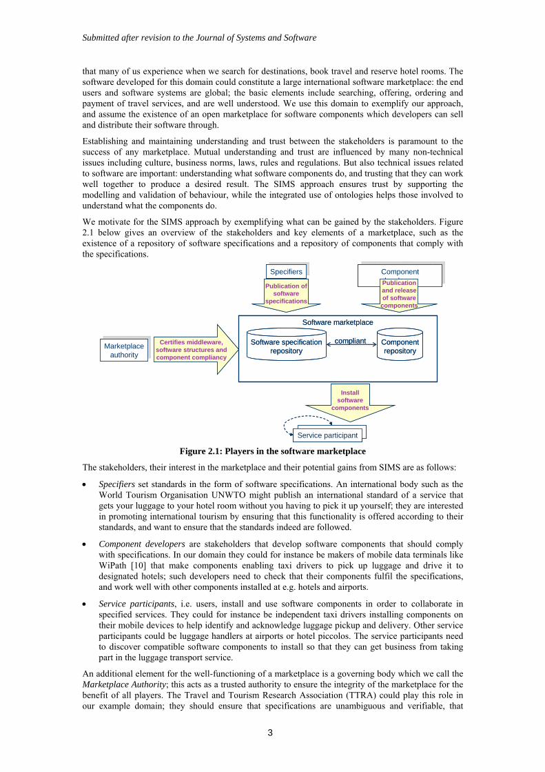
We motivate for the SIMS approach by exemplifying what can be gained by the stakeholders. Figure 2.1 below gives an overview of the stakeholders and key elements of a marketplace, such as the existence of a repository of software specifications and a repository of components that comply with the specifications.
Service participant
Software marketplace
Software specificationrepository
Componentrepository
Certifies middleware,software structures andcomponent compliancy
SpecifiersSpecifiers Component developers
Component developers
Service participant
Publication ofsoftware
specifications
Publicationand releaseof software
components
Installsoftware
components
Marketplaceauthority
Marketplaceauthority
compliant
Service participant
Software marketplace
Software specificationrepository
Componentrepository
Certifies middleware,software structures andcomponent compliancy
SpecifiersSpecifiers Component developers
Component developers
Service participant
Publication ofsoftware
specifications
Publicationand releaseof software
components
Installsoftware
components
Marketplaceauthority
Marketplaceauthority
compliant
Figure 2.1: Players in the software marketplace
The stakeholders, their interest in the marketplace and their potential gains from SIMS are as follows:
Specifiers set standards in the form of software specifications. An international body such as the World Tourism Organisation UNWTO might publish an international standard of a service that gets your luggage to your hotel room without you having to pick it up yourself; they are interested in promoting international tourism by ensuring that this functionality is offered according to their standards, and want to ensure that the standards indeed are followed.
Component developers are stakeholders that develop software components that should comply with specifications. In our domain they could for instance be makers of mobile data terminals like WiPath [10] that make components enabling taxi drivers to pick up luggage and drive it to designated hotels; such developers need to check that their components fulfil the specifications, and work well with other components installed at e.g. hotels and airports.
Service participants, i.e. users, install and use software components in order to collaborate in specified services. They could for instance be independent taxi drivers installing components on their mobile devices to help identify and acknowledge luggage pickup and delivery. Other service participants could be luggage handlers at airports or hotel piccolos. The service participants need to discover compatible software components to install so that they can get business from taking part in the luggage transport service.
An additional element for the well-functioning of a marketplace is a governing body which we call the Marketplace Authority; this acts as a trusted authority to ensure the integrity of the marketplace for the benefit of all players. The Travel and Tourism Research Association (TTRA) could play this role in our example domain; they should ensure that specifications are unambiguous and verifiable, that
Submitted after revision to the Journal of Systems and Software
4
components offered on the marketplace are indeed compliant with the specifications, and collect information about the installation or use of components.
As noted above, the well-functioning of a software marketplace sets a number of requirements to the methods and tools used:
The proper working of a software marketplace requires standardisation of the terminology of the domain. This is where ontology techniques come in to establish a common meaning of terms. For instance what a confirmation of a luggage pick-up is about.
Software specifications should express unambiguously and in a verifiable manner the interaction behaviour between components that collaborate in a service. For instance the interaction between the taxi role and the piccolo role should be formally specified.
The behaviour of components should be verified against specifications, so that it is clear if, say, a certain taxi system complies with the specification of the luggage pickup service.
Underlying middleware systems should support end users in discovering software components that fulfil new needs. For instance, taxi drivers that pick up travellers at airports through orders from Hotels.com may discover components that enable them to take part in the luggage pickup service.
Underlying middleware systems should support consistency checking between components assembled at runtime. As end users are offered the ability to discover and easily deploy new functionalities, strengthened support for ensuring compatibility guarantees should be provided.
These requirements are addressed by the SIMS approach presented in the following sections.
3 Introduction to SIMS service engineering approach
This section presents the concepts underlying the SIMS service engineering approach and introduces the modelling and validation techniques. More details are presented in sections 4, 5 and 6.
3.1 Main service concepts
The central concept of SIMS is the concept of collaborative service. Collaborative services deliver some functionality to service users in the system environment. They result from the collaboration, i.e. interactions, between autonomous entities that may take initiatives concurrently. A collaborative service may involve multiple users, i.e. service participants. In the following we simply use the short term “service” to mean collaborative service.
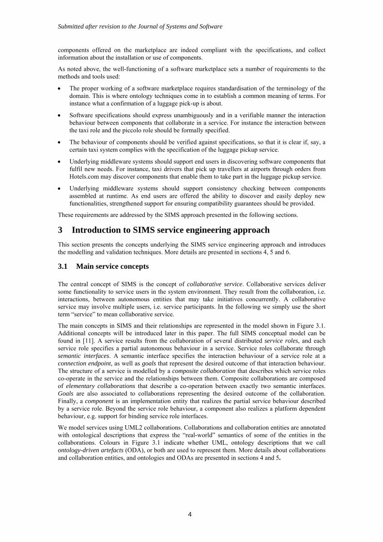
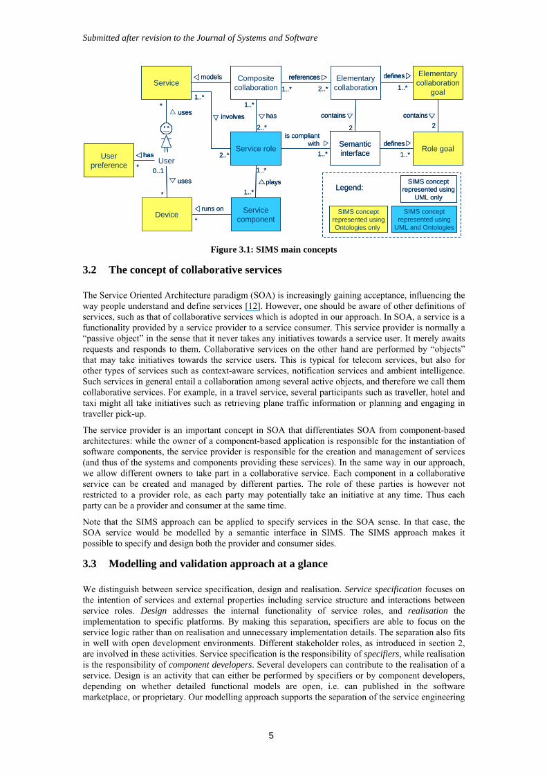
The main concepts in SIMS and their relationships are represented in the model shown in Figure 3.1. Additional concepts will be introduced later in this paper. The full SIMS conceptual model can be found in [11]. A service results from the collaboration of several distributed service roles, and each service role specifies a partial autonomous behaviour in a service. Service roles collaborate through semantic interfaces. A semantic interface specifies the interaction behaviour of a service role at a connection endpoint, as well as goals that represent the desired outcome of that interaction behaviour. The structure of a service is modelled by a composite collaboration that describes which service roles co-operate in the service and the relationships between them. Composite collaborations are composed of elementary collaborations that describe a co-operation between exactly two semantic interfaces. Goals are also associated to collaborations representing the desired outcome of the collaboration. Finally, a component is an implementation entity that realizes the partial service behaviour described by a service role. Beyond the service role behaviour, a component also realizes a platform dependent behaviour, e.g. support for binding service role interfaces.
We model services using UML2 collaborations. Collaborations and collaboration entities are annotated with ontological descriptions that express the “real-world” semantics of some of the entities in the collaborations. Colours in Figure 3.1 indicate whether UML, ontology descriptions that we call ontology-driven artefacts (ODA), or both are used to represent them. More details about collaborations and collaboration entities, and ontologies and ODAs are presented in sections 4 and 5.
Submitted after revision to the Journal of Systems and Software
5
2..*
involves
1..*
1..*
1..*
plays
Service role Role goal
is compliantwith
1..*
defines
1..*
Compositecollaboration
Elementarycollaboration
contains
2
has
2..*
1..*2..*1..*
1..*
defines Elementarycollaboration
goal
contains
Deviceruns on
Userpreference
*
*
models
2
SIMS conceptrepresented usingOntologies only
SIMS conceptrepresented using
UML only
Legend:
SIMS conceptrepresented using
UML and Ontologies
*
0..1
references
uses
uses
Semanticinterface
Service
Servicecomponent
Userhas
*
2..*
involvesinvolves
1..*
1..*
1..*
playsplays
Service role Role goal
is compliantwith
1..*
definesdefines
1..*
Compositecollaboration
Elementarycollaboration
containscontains
2
has
2..*
1..*2..*1..*
1..*
definesdefines Elementarycollaboration
goal
containscontains
Deviceruns on
Userpreference
*
*
models
2
SIMS conceptrepresented usingOntologies only
SIMS conceptrepresented using
UML only
Legend:
SIMS conceptrepresented using
UML and Ontologies
*
0..1
referencesreferences
uses
usesuses
Semanticinterface
Service
Servicecomponent
Userhashas
*
Figure 3.1: SIMS main concepts
3.2 The concept of collaborative services
The Service Oriented Architecture paradigm (SOA) is increasingly gaining acceptance, influencing the way people understand and define services [12]. However, one should be aware of other definitions of services, such as that of collaborative services which is adopted in our approach. In SOA, a service is a functionality provided by a service provider to a service consumer. This service provider is normally a “passive object” in the sense that it never takes any initiatives towards a service user. It merely awaits requests and responds to them. Collaborative services on the other hand are performed by “objects” that may take initiatives towards the service users. This is typical for telecom services, but also for other types of services such as context-aware services, notification services and ambient intelligence. Such services in general entail a collaboration among several active objects, and therefore we call them collaborative services. For example, in a travel service, several participants such as traveller, hotel and taxi might all take initiatives such as retrieving plane traffic information or planning and engaging in traveller pick-up.
The service provider is an important concept in SOA that differentiates SOA from component-based architectures: while the owner of a component-based application is responsible for the instantiation of software components, the service provider is responsible for the creation and management of services (and thus of the systems and components providing these services). In the same way in our approach, we allow different owners to take part in a collaborative service. Each component in a collaborative service can be created and managed by different parties. The role of these parties is however not restricted to a provider role, as each party may potentially take an initiative at any time. Thus each party can be a provider and consumer at the same time.
Note that the SIMS approach can be applied to specify services in the SOA sense. In that case, the SOA service would be modelled by a semantic interface in SIMS. The SIMS approach makes it possible to specify and design both the provider and consumer sides.
3.3 Modelling and validation approach at a glance
We distinguish between service specification, design and realisation. Service specification focuses on the intention of services and external properties including service structure and interactions between service roles. Design addresses the internal functionality of service roles, and realisation the implementation to specific platforms. By making this separation, specifiers are able to focus on the service logic rather than on realisation and unnecessary implementation details. The separation also fits in well with open development environments. Different stakeholder roles, as introduced in section 2, are involved in these activities. Service specification is the responsibility of specifiers, while realisation is the responsibility of component developers. Several developers can contribute to the realisation of a service. Design is an activity that can either be performed by specifiers or by component developers, depending on whether detailed functional models are open, i.e. can published in the software marketplace, or proprietary. Our modelling approach supports the separation of the service engineering
Submitted after revision to the Journal of Systems and Software
6
activities. Moreover, our validation techniques allow stakeholders to check their models and thus guarantee the quality of results they deliver to other stakeholders.
To facilitate the understanding of the SIMS service engineering techniques and the relationships between them, we have described three development processes: the top-down, bottom-up and reuse approaches. The top-down approach, further described in this section, can be applied when a service is defined from scratch. It progresses by refinement, starting from a high-level specification of the system, and resulting in a fine-grained specification of the interfaces and service role behaviours. The bottom-up approach is a kind of re-engineering approach that supports creating SIMS components out of non-SIMS components. The reuse approach highlights the reuse of existing service specifications. Other processes that exploit SIMS techniques might also be defined. For example, iterations supporting the refinement of specifications might be introduced in the top-down approach.
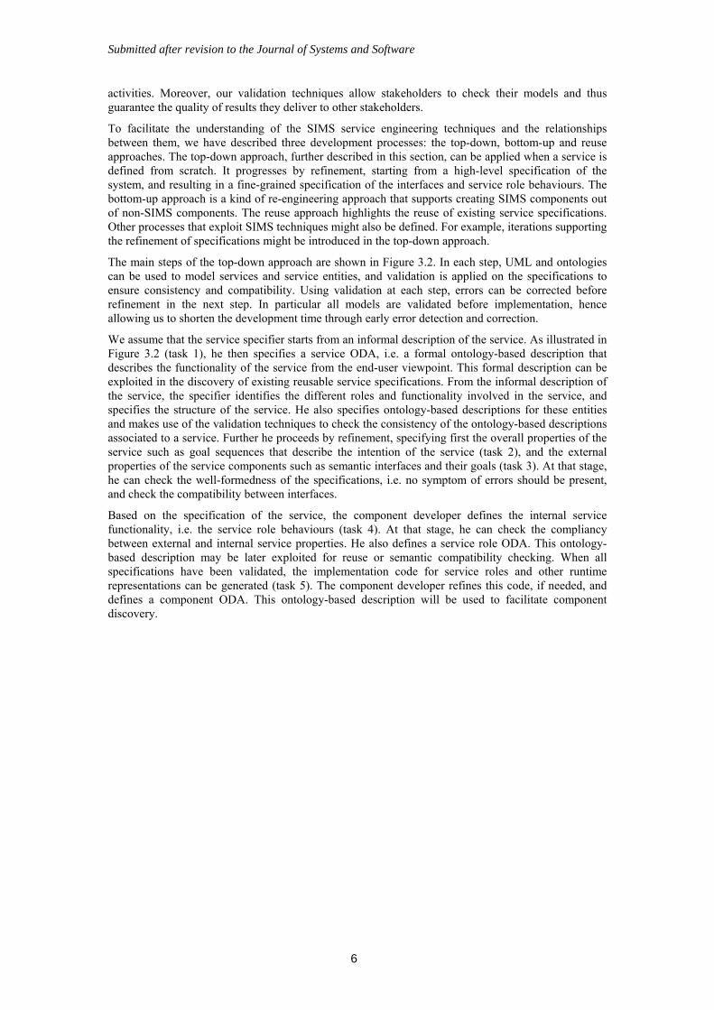
The main steps of the top-down approach are shown in Figure 3.2. In each step, UML and ontologies can be used to model services and service entities, and validation is applied on the specifications to ensure consistency and compatibility. Using validation at each step, errors can be corrected before refinement in the next step. In particular all models are validated before implementation, hence allowing us to shorten the development time through early error detection and correction.
We assume that the service specifier starts from an informal description of the service. As illustrated in Figure 3.2 (task 1), he then specifies a service ODA, i.e. a formal ontology-based description that describes the functionality of the service from the end-user viewpoint. This formal description can be exploited in the discovery of existing reusable service specifications. From the informal description of the service, the specifier identifies the different roles and functionality involved in the service, and specifies the structure of the service. He also specifies ontology-based descriptions for these entities and makes use of the validation techniques to check the consistency of the ontology-based descriptions associated to a service. Further he proceeds by refinement, specifying first the overall properties of the service such as goal sequences that describe the intention of the service (task 2), and the external properties of the service components such as semantic interfaces and their goals (task 3). At that stage, he can check the well-formedness of the specifications, i.e. no symptom of errors should be present, and check the compatibility between interfaces.
Based on the specification of the service, the component developer defines the internal service functionality, i.e. the service role behaviours (task 4). At that stage, he can check the compliancy between external and internal service properties. He also defines a service role ODA. This ontology-based description may be later exploited for reuse or semantic compatibility checking. When all specifications have been validated, the implementation code for service roles and other runtime representations can be generated (task 5). The component developer refines this code, if needed, and defines a component ODA. This ontology-based description will be used to facilitate component discovery.
Submitted after revision to the Journal of Systems and Software
7
1. Specify:structure of the service
2. Specify:intention of the service
3. Specify:semantic interfaces
4. Design:service roles
(Semantic Interface)Role goal ODA
Service ODA
Component ODA
Compositecollaboration
Elementarycollaboration
State machine diagram
Goal sequence: activity diagram
Ontology descriptions
Validation
Well-formedness
Well-formedness
Compatibility,Sub-typing
Compliancy√
√
UML models
√
√
√
Consistency
Task
State machine diagram
DeviceODA
Elem. Collab.Goal ODA
Service ODA 0
DeviceODA
√
Constraints meet
Service roleODA
5. Implement:components
[Code generation]
1. Specify:structure of the service
2. Specify:intention of the service
3. Specify:semantic interfaces
4. Design:service roles
(Semantic Interface)Role goal ODA
(Semantic Interface)Role goal ODA
Service ODA
Component ODA
Component ODA
Compositecollaboration
Elementarycollaboration
State machine diagram
Goal sequence: activity diagram
Ontology descriptions
Validation
Well-formedness
Well-formedness
Compatibility,Sub-typing
Compliancy√
√
UML models
√
√
√
Consistency
Task
State machine diagram
DeviceODA
DeviceODA
Elem. Collab.Goal ODA
Elem. Collab.Goal ODA
Service ODA 0
DeviceODA0
DeviceODA
√
Constraints meet
Service roleODA
Service roleODA
5. Implement:components
[Code generation][Code generation]
Figure 3.2: Top-down approach
4 Service specification and design
This section addresses service specification and design using UML. We exploit collaborations (composite structure diagrams) to model the structural properties of services, and state machines and activity diagrams to model the behavioural properties. We distinguish between the external behavioural properties, i.e. goal sequences and semantic interfaces, and the internal behavioural properties, i.e. service roles. External properties are useful for understanding and validating a service composition, and internal properties for understanding service realizations and checking compliancy of a realization with respect to a composition. Our approach introduces a number of diagram views, which takes some effort to grasp. However, they keep separate different concerns, e.g. service intention and detailed behaviour. Also, elementary collaborations and semantic interfaces describe reusable entities. We provide tools allowing developers to maintain consistency between views. They will be presented in section 6.
4.1 Collaborations
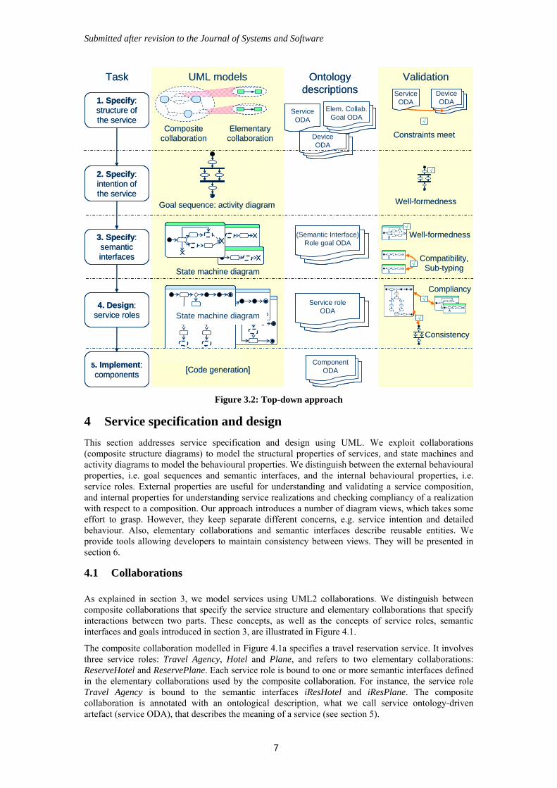
As explained in section 3, we model services using UML2 collaborations. We distinguish between composite collaborations that specify the service structure and elementary collaborations that specify interactions between two parts. These concepts, as well as the concepts of service roles, semantic interfaces and goals introduced in section 3, are illustrated in Figure 4.1.
The composite collaboration modelled in Figure 4.1a specifies a travel reservation service. It involves three service roles: Travel Agency, Hotel and Plane, and refers to two elementary collaborations: ReserveHotel and ReservePlane. Each service role is bound to one or more semantic interfaces defined in the elementary collaborations used by the composite collaboration. For instance, the service role Travel Agency is bound to the semantic interfaces iResHotel and iResPlane. The composite collaboration is annotated with an ontological description, what we call service ontology-driven artefact (service ODA), that describes the meaning of a service (see section 5).
Submitted after revision to the Journal of Systems and Software
8
The elementary collaborations are modelled in Figure 4.1b. Each elementary collaboration refers to two semantic interfaces. The arrow between the semantic interfaces indicates which of them initiates the interaction (i.e. sends the first message). Elementary collaborations define one or more goals that represent desired outcomes of the collaboration. For example, RoomReserved or OptionOnRoom are goals that might be achieved by ReserveHotel. Note that goals are not necessarily achieved during an interaction, e.g. the hotel may not have any rooms left.
a) Composite Collaboration b) Elementary Collaboration
a:Travel
Agency
p:Plane
h:Hotel
iResHoteliHotel
iPlane
iResPlane
TravelReservation
rp:ReservePlane
rh:ReserveHotel
Service role
ServiceODA: travel reservation service
Collaboration use
Service ODA
iResplane:iResPlane_SM
iPlane:iPlane_SM
ReservePlane
Goals: SeatReserved
ReserveHotel
iResHotel:iResHotel_SM
iHotel:iHotel_SM
Goals: RoomReserved, OptionOnRoom
Semantic Interface, with its role name and the associated type
List of goals achievable by the semantic interfaces
a) Composite Collaboration b) Elementary Collaboration
a:Travel
Agency
p:Plane
h:Hotel
iResHoteliHotel
iPlane
iResPlane
TravelReservation
rp:ReservePlane
rh:ReserveHotel
Service role
ServiceODA: travel reservation service
Collaboration use
Service ODA
a:Travel
Agency
p:Plane
h:Hotel
iResHoteliHotel
iPlane
iResPlane
TravelReservation
rp:ReservePlane
rh:ReserveHotel
Service role
ServiceODA: travel reservation service
Collaboration use
Service ODA
iResplane:iResPlane_SM
iPlane:iPlane_SM
ReservePlane
Goals: SeatReserved
ReserveHotel
iResHotel:iResHotel_SM
iHotel:iHotel_SM
Goals: RoomReserved, OptionOnRoom
Semantic Interface, with its role name and the associated type
List of goals achievable by the semantic interfaces
iResplane:iResPlane_SM
iPlane:iPlane_SM
ReservePlane
Goals: SeatReserved
iResplane:iResPlane_SM
iPlane:iPlane_SM
ReservePlane
Goals: SeatReserved
ReserveHotel
iResHotel:iResHotel_SM
iHotel:iHotel_SM
Goals: RoomReserved, OptionOnRoom
ReserveHotel
iResHotel:iResHotel_SM
iHotel:iHotel_SM
Goals: RoomReserved, OptionOnRoom
Semantic Interface, with its role name and the associated type
List of goals achievable by the semantic interfaces
Figure 4.1: Composite and elementary collaborations
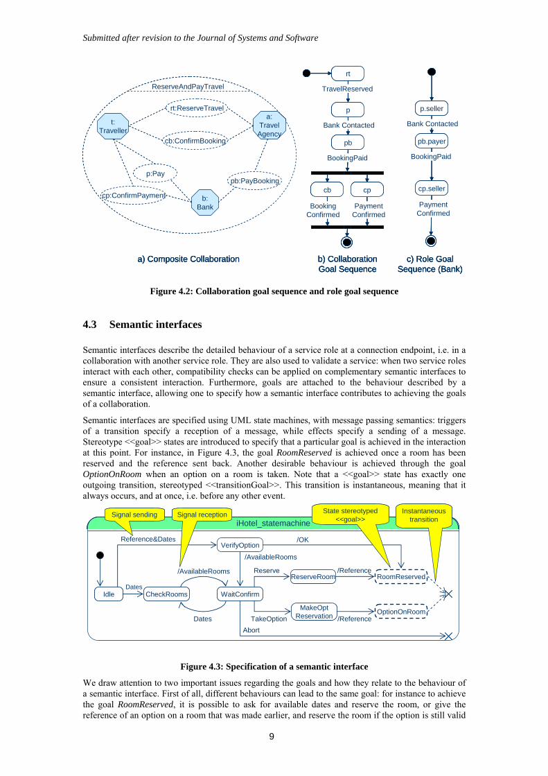
4.2 Goal Sequences
A goal sequence is a high level specification of a desirable behaviour. It specifies how goals depend on each other in terms of preconditions. Beyond providing an intuitive description of the intention of a service or service role, goal sequences are used to verify that a composition is live, i.e. to check that something useful may be achieved in a service. We distinguish between Collaboration Goal Sequences and Role Goal Sequences. The former applies to a composite collaboration and relates to elementary collaboration goals; the latter applies to a service role and relates to the semantic interface goals. A collaboration goal sequence describes something useful that can be achieved in a collaborative service, and how it should be achieved, i.e. how goals should be sequenced. A role goal sequence specifies the pre-conditions between goals at the service role level. It specifies how the service role should sequence the goals of its semantic interfaces.
Collaboration and role goal sequences are specified using activity diagrams, where each activity represents a goal to be achieved (i.e. the behaviour to be performed in order to fulfil that goal). Concerning collaboration goal sequences, each activity refers by name to a particular collaboration use of the composite collaboration. Concerning role goal sequences, each activity refers by name to a particular semantic interface bound to the corresponding service role. More details about goal sequences can be found in [13].
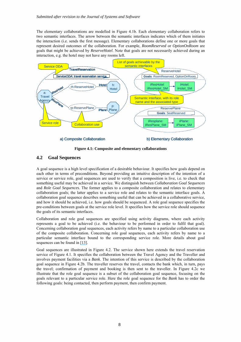
Goal sequences are illustrated in Figure 4.2. The service shown here extends the travel reservation service of Figure 4.1. It specifies the collaboration between the Travel Agency and the Traveller and involves payment facilities via a Bank. The intention of this service is described by the collaboration goal sequence in Figure 4.2b. The traveller reserves the travel, contacts the bank which, in turn, pays the travel; confirmation of payment and booking is then sent to the traveller. In Figure 4.2c we illustrate that the role goal sequence is a subset of the collaboration goal sequence, focusing on the goals relevant to a particular service role. Here the role goal sequence for the Bank has to order the following goals: being contacted, then perform payment, then confirm payment.
Submitted after revision to the Journal of Systems and Software
9
ReserveAndPayTravel
a) Composite Collaboration
t:Traveller
a:TravelAgency
cb:ConfirmBooking
rt:ReserveTravel
b:Bank
pb:PayBookingp:Pay
cp:ConfirmPayment
Bank Contacted
PaymentConfirmed
BookingPaid
c) Role GoalSequence (Bank)
p.seller
pb.payer
cp.seller
rt
b) CollaborationGoal Sequence
Bank Contacted
p
BookingPaid
pb
cb cp
BookingConfirmed
PaymentConfirmed
TravelReservedReserveAndPayTravel
a) Composite Collaboration
t:Traveller
a:TravelAgency
cb:ConfirmBooking
rt:ReserveTravel
b:Bank
pb:PayBookingp:Pay
cp:ConfirmPayment
ReserveAndPayTravel
a) Composite Collaboration
t:Traveller
a:TravelAgency
cb:ConfirmBookingcb:ConfirmBooking
rt:ReserveTravelrt:ReserveTravel
b:Bank
pb:PayBookingpb:PayBookingp:Payp:Pay
cp:ConfirmPaymentcp:ConfirmPayment
Bank Contacted
PaymentConfirmed
BookingPaid
c) Role GoalSequence (Bank)
p.seller
pb.payer
cp.seller
Bank Contacted
PaymentConfirmed
BookingPaid
c) Role GoalSequence (Bank)
p.seller
pb.payer
cp.seller
rt
b) CollaborationGoal Sequence
Bank Contacted
p
BookingPaid
pb
cb cp
BookingConfirmed
PaymentConfirmed
TravelReserved
rt
b) CollaborationGoal Sequence
Bank Contacted
p
BookingPaid
pb
cb cp
BookingConfirmed
PaymentConfirmed
TravelReserved
Figure 4.2: Collaboration goal sequence and role goal sequence
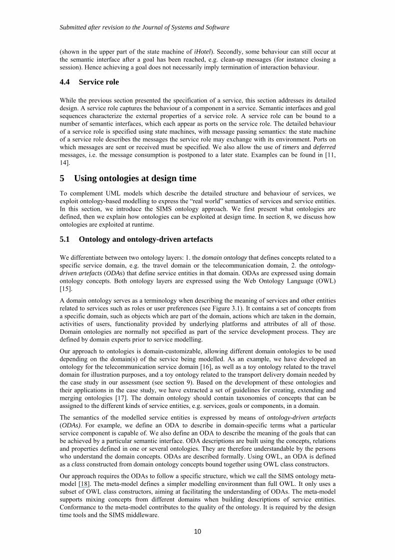
4.3 Semantic interfaces
Semantic interfaces describe the detailed behaviour of a service role at a connection endpoint, i.e. in a collaboration with another service role. They are also used to validate a service: when two service roles interact with each other, compatibility checks can be applied on complementary semantic interfaces to ensure a consistent interaction. Furthermore, goals are attached to the behaviour described by a semantic interface, allowing one to specify how a semantic interface contributes to achieving the goals of a collaboration.
Semantic interfaces are specified using UML state machines, with message passing semantics: triggers of a transition specify a reception of a message, while effects specify a sending of a message. Stereotype <<goal>> states are introduced to specify that a particular goal is achieved in the interaction at this point. For instance, in Figure 4.3, the goal RoomReserved is achieved once a room has been reserved and the reference sent back. Another desirable behaviour is achieved through the goal OptionOnRoom when an option on a room is taken. Note that a <<goal>> state has exactly one outgoing transition, stereotyped <<transitionGoal>>. This transition is instantaneous, meaning that it always occurs, and at once, i.e. before any other event.
Idle CheckRooms WaitConfirm
ReserveRoom
MakeOptReservation
RoomReserved
Dates
/AvailableRooms
Reference&Dates
Dates
Reserve
TakeOption
Abort
/Reference
/Reference
iHotel_statemachine
VerifyOption/OK
/AvailableRooms
State stereotyped <<goal>>
OptionOnRoom
Instantaneous transition
Signal sending Signal reception
IdleIdle CheckRoomsCheckRooms WaitConfirmWaitConfirm
ReserveRoomReserveRoom
MakeOptReservation
MakeOptReservation
RoomReservedRoomReserved
Dates
/AvailableRooms
Reference&Dates
Dates
Reserve
TakeOption
Abort
/Reference
/Reference
iHotel_statemachine
VerifyOption/OK
/AvailableRooms
State stereotyped <<goal>>
OptionOnRoomOptionOnRoom
Instantaneous transition
Signal sending Signal reception
Figure 4.3: Specification of a semantic interface
We draw attention to two important issues regarding the goals and how they relate to the behaviour of a semantic interface. First of all, different behaviours can lead to the same goal: for instance to achieve the goal RoomReserved, it is possible to ask for available dates and reserve the room, or give the reference of an option on a room that was made earlier, and reserve the room if the option is still valid
Submitted after revision to the Journal of Systems and Software
10
(shown in the upper part of the state machine of iHotel). Secondly, some behaviour can still occur at the semantic interface after a goal has been reached, e.g. clean-up messages (for instance closing a session). Hence achieving a goal does not necessarily imply termination of interaction behaviour.
4.4 Service role
While the previous section presented the specification of a service, this section addresses its detailed design. A service role captures the behaviour of a component in a service. Semantic interfaces and goal sequences characterize the external properties of a service role. A service role can be bound to a number of semantic interfaces, which each appear as ports on the service role. The detailed behaviour of a service role is specified using state machines, with message passing semantics: the state machine of a service role describes the messages the service role may exchange with its environment. Ports on which messages are sent or received must be specified. We also allow the use of timers and deferred messages, i.e. the message consumption is postponed to a later state. Examples can be found in [11, 14].
5 Using ontologies at design time
To complement UML models which describe the detailed structure and behaviour of services, we exploit ontology-based modelling to express the “real world” semantics of services and service entities. In this section, we introduce the SIMS ontology approach. We first present what ontologies are defined, then we explain how ontologies can be exploited at design time. In section 8, we discuss how ontologies are exploited at runtime.
5.1 Ontology and ontology-driven artefacts
We differentiate between two ontology layers: 1. the domain ontology that defines concepts related to a specific service domain, e.g. the travel domain or the telecommunication domain, 2. the ontology-driven artefacts (ODAs) that define service entities in that domain. ODAs are expressed using domain ontology concepts. Both ontology layers are expressed using the Web Ontology Language (OWL) [15].
A domain ontology serves as a terminology when describing the meaning of services and other entities related to services such as roles or user preferences (see Figure 3.1). It contains a set of concepts from a specific domain, such as objects which are part of the domain, actions which are taken in the domain, activities of users, functionality provided by underlying platforms and attributes of all of those. Domain ontologies are normally not specified as part of the service development process. They are defined by domain experts prior to service modelling.
Our approach to ontologies is domain-customizable, allowing different domain ontologies to be used depending on the domain(s) of the service being modelled. As an example, we have developed an ontology for the telecommunication service domain [16], as well as a toy ontology related to the travel domain for illustration purposes, and a toy ontology related to the transport delivery domain needed by the case study in our assessment (see section 9). Based on the development of these ontologies and their applications in the case study, we have extracted a set of guidelines for creating, extending and merging ontologies [17]. The domain ontology should contain taxonomies of concepts that can be assigned to the different kinds of service entities, e.g. services, goals or components, in a domain.
The semantics of the modelled service entities is expressed by means of ontology-driven artefacts (ODAs). For example, we define an ODA to describe in domain-specific terms what a particular service component is capable of. We also define an ODA to describe the meaning of the goals that can be achieved by a particular semantic interface. ODA descriptions are built using the concepts, relations and properties defined in one or several ontologies. They are therefore understandable by the persons who understand the domain concepts. ODAs are described formally. Using OWL, an ODA is defined as a class constructed from domain ontology concepts bound together using OWL class constructors.
Our approach requires the ODAs to follow a specific structure, which we call the SIMS ontology meta-model [18]. The meta-model defines a simpler modelling environment than full OWL. It only uses a subset of OWL class constructors, aiming at facilitating the understanding of ODAs. The meta-model supports mixing concepts from different domains when building descriptions of service entities. Conformance to the meta-model contributes to the quality of the ontology. It is required by the design time tools and the SIMS middleware.
Submitted after revision to the Journal of Systems and Software
11
5.2 ODA types
As shown in Figure 3.1, various service entities are modelled using ontologies. We introduce a set of ODA types that are used for modelling entities. The types are themselves defined in a domain independent ontology, the ontology of SIMS entities. The ODA types are listed below. For each ODA type, we exemplify what information can be associated to the type in the case the travel service domain ontology is used:
Service ODA. This ODA type describes the type of service (e.g., hotel or plane reservation service) along with its attributes (e.g., available accommodation types or possible routes).
Service Role ODA. This ODA type describes the kind of role played in a service or a set of services (e.g., a travel agency or a bank).
Elementary collaboration goal ODA. This ODA type describes the goals that can be achieved in an elementary collaboration (e.g., booking of a plane or reservation of a restaurant).
Role goal ODA. This ODA type describes the goals that can be achieved by a semantic interface in an elementary collaboration (e.g., credit card payment for a service). The concepts of role goal ODA and elementary collaboration goal ODA are close concepts, but relate to different entities. Further the role goal ODA may indicate whether a semantic interface is initiating or not.
Component ODA. This ODA type describes the features of a component (e.g., a service it contributes to, or the goals which can be achieved by the component) and components’ requirements (e.g., requirements on the software and hardware platform).
Device ODA. This ODA type describes capabilities of devices. It includes a description of the device category (e.g., smart phone, PDA or laptop) and its detailed characteristics (e.g., hardware features such as display and audio features or networking, and software features such as installed browser, available instant messaging applications or multimedia codecs).
User preferences ODA. This ODA type describes the preferences of users on the service behaviour such as the goals a user wish to achieve or attributes of the service (e.g., services that fit a specific user disability). This ODA is used at runtime to facilitate component discovery.
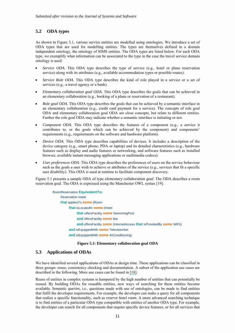
Figure 5.1 presents a sample ODA of type elementary collaboration goal. The ODA describes a room reservation goal. The ODA is expressed using the Manchester OWL syntax [19].
RoomReservation EquivalentTo:Reservation made
that appliesTo some (Room
that isLocatedIn some (Hotel
that offersFacility some SwimmingPool
and offersFacility some Bar
and offersFacility some (InternetAccess that isProvidedBy some WiFi))
and isEquippedWith some TelevisionSet
and isEquippedWith some AirConditioning)
Figure 5.1: Elementary collaboration goal ODA
5.3 Applications of ODAs
We have identified several applications of ODAs at design time. These applications can be classified in three groups: reuse, consistency checking and documentation. A subset of the application use cases are described in the following. More use cases can be found in [18].
Reuse of entities in complex systems is hampered by the high number of entities that can potentially be reused. By building ODAs for reusable entities, new ways of searching for these entities become available. Semantic queries, i.e., questions made with use of ontologies, can be made to find entities that fulfil the developer requirements. For example, the developer can make a query for all components that realize a specific functionality, such as reserve hotel room. A more advanced searching technique is to find entities of a particular ODA type compatible with entities of another ODA type. For example, the developer can search for all components that require specific device features, or for all services that
Submitted after revision to the Journal of Systems and Software
12
can be used to achieve a specific goal, or for all components which can collaborate with a specific component in a service.
ODA-based consistency checking is complementary to the validation of behavioural consistency of detailed service behaviour (see section 6). For example, while the validation approach allows the developer to check that two interfaces might achieve complementary goals at some stage in a service, ODA reasoning makes it possible to check that these goals are semantically consistent. Another example relates to checking the consistency between the capabilities required by a service or a service component and the capabilities provided by a device.
As far as documentation is concerned, ODAs can be processed and transformed into a form that is easier to understand by the developers. We both support the generation of natural language descriptions that explain what ODAs are about, and the Manchester OWL syntax [19]. The Manchester OWL syntax is more precise that natural language and is a useful tool when creating ODAs, since the complete structure of the ODA can be shown.
5.4 Realization of the ODA use cases
To realize the functionality described by use cases presented in the previous sub-section, we have developed ODA matching techniques based on state-of-the-art matching techniques available for Semantic Web Services technologies [20, 21].
We exploit existing techniques to support the matching of ODAs of the same type, e.g., matching of ODAs of a service ODA type. If A (Advertisement) represents the ODA associated to an entity stored in a repository, and R (Request) a query for an entity of the same type expressed by the developer, we support three kinds of matching: exact matching (when A R), plug-in matching meaning that the advertisement is a sub-concept of the request (when A ⊑ R), and subsumption matching meaning that the request is a sub-concept of the advertisement (when R ⊑ A). For instance if R denotes the desired feature of a service, plug-in matching is used to identify appropriate services. This matching technique is for discovery and reuse of existing service entities (e.g., components).
We have extended matching techniques to support the matching of ODAs of different types, e.g., matching of component ODA and device ODA. We first need to extract the parts of the ODA class expression which describes the same class of objects. For example, we might extract the information related to device requirements from a component ODA in order to check the compatibility between a component and a device. This extraction results in a new ODA that can be compared against the device ODA. The same matching techniques as described above, i.e. exact matching, plug-in matching and subsumption matching, can the be applied.
Matching, in either case, takes advantage of the reasoning capabilities provided by the underlying ontology platform that includes the off-the-shelf reasoning engine Pellet [22]. Reasoning allows discovering ‘compatibility’ of descriptions even if they are syntactically different. For example, the goal shown in Figure 5.1 relates, among others, to a hotel room that offers “WiFi”. By using reasoning, this goal will be discovered in a query that describes a “wireless-based Internet access” because WiFi is wireless. It will also be discovered if the Internet access type is not specified at all. This matching technique is applied for consistency checking.
To generate a natural language description of an ODA, we make an analysis of the ODA structure: we collect the concepts and relations the ODA contains, and we check how they are used within restrictions and class constructs such as intersections and unions. While the names of the classes and relations are used as a source of vocabulary for the natural language description, the structure of the restrictions and class constructs are transformed to conjunctions, e.g. “that”, “and” and “or”, that bind the classes in correct sentences. This technique is applied for documentation purposes.
6 Validation of behaviour
SIMS validation techniques exploit the UML specifications to check the safety and liveness properties of services, i.e. checking that “bad things never can happen” and “something good can sometimes happen” [23]. Validation is applied incrementally, first on pairs of semantic interfaces in an elementary collaboration, then on a composition. We also provide techniques for checking the compliancy between service roles and a service composition. A major concern in our work has been to develop techniques that can be applied at design time, but also at runtime, thus supporting consistency checking of dynamically composed services. Runtime validation requires algorithmic complexity to be kept low,
Submitted after revision to the Journal of Systems and Software
13
or analysis of small state spaces. Another concern has been to integrate the validation approach in the development process and use concepts that are easy to use and understand by software developers. As few software developers have competence in formal methods, we have chosen to present the validation techniques using UML concepts for behaviour modelling that the developers are familiar with.
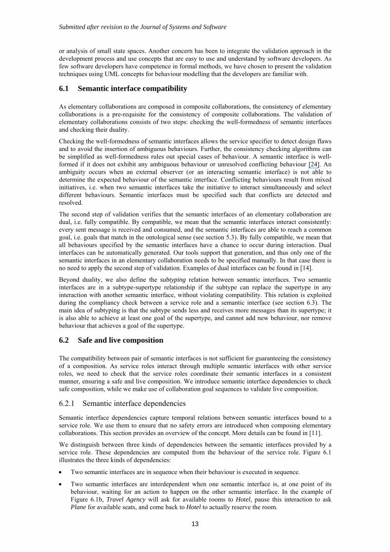
6.1 Semantic interface compatibility
As elementary collaborations are composed in composite collaborations, the consistency of elementary collaborations is a pre-requisite for the consistency of composite collaborations. The validation of elementary collaborations consists of two steps: checking the well-formedness of semantic interfaces and checking their duality.
Checking the well-formedness of semantic interfaces allows the service specifier to detect design flaws and to avoid the insertion of ambiguous behaviours. Further, the consistency checking algorithms can be simplified as well-formedness rules out special cases of behaviour. A semantic interface is well-formed if it does not exhibit any ambiguous behaviour or unresolved conflicting behaviour [24]. An ambiguity occurs when an external observer (or an interacting semantic interface) is not able to determine the expected behaviour of the semantic interface. Conflicting behaviours result from mixed initiatives, i.e. when two semantic interfaces take the initiative to interact simultaneously and select different behaviours. Semantic interfaces must be specified such that conflicts are detected and resolved.
The second step of validation verifies that the semantic interfaces of an elementary collaboration are dual, i.e. fully compatible. By compatible, we mean that the semantic interfaces interact consistently: every sent message is received and consumed, and the semantic interfaces are able to reach a common goal, i.e. goals that match in the ontological sense (see section 5.3). By fully compatible, we mean that all behaviours specified by the semantic interfaces have a chance to occur during interaction. Dual interfaces can be automatically generated. Our tools support that generation, and thus only one of the semantic interfaces in an elementary collaboration needs to be specified manually. In that case there is no need to apply the second step of validation. Examples of dual interfaces can be found in [14].
Beyond duality, we also define the subtyping relation between semantic interfaces. Two semantic interfaces are in a subtype-supertype relationship if the subtype can replace the supertype in any interaction with another semantic interface, without violating compatibility. This relation is exploited during the compliancy check between a service role and a semantic interface (see section 6.3). The main idea of subtyping is that the subtype sends less and receives more messages than its supertype; it is also able to achieve at least one goal of the supertype, and cannot add new behaviour, nor remove behaviour that achieves a goal of the supertype.
6.2 Safe and live composition
The compatibility between pair of semantic interfaces is not sufficient for guaranteeing the consistency of a composition. As service roles interact through multiple semantic interfaces with other service roles, we need to check that the service roles coordinate their semantic interfaces in a consistent manner, ensuring a safe and live composition. We introduce semantic interface dependencies to check safe composition, while we make use of collaboration goal sequences to validate live composition.
6.2.1 Semantic interface dependencies
Semantic interface dependencies capture temporal relations between semantic interfaces bound to a service role. We use them to ensure that no safety errors are introduced when composing elementary collaborations. This section provides an overview of the concept. More details can be found in [11].
We distinguish between three kinds of dependencies between the semantic interfaces provided by a service role. These dependencies are computed from the behaviour of the service role. Figure 6.1 illustrates the three kinds of dependencies:
Two semantic interfaces are in sequence when their behaviour is executed in sequence.
Two semantic interfaces are interdependent when one semantic interface is, at one point of its behaviour, waiting for an action to happen on the other semantic interface. In the example of Figure 6.1b, Travel Agency will ask for available rooms to Hotel, pause this interaction to ask Plane for available seats, and come back to Hotel to actually reserve the room.

Submitted after revision to the Journal of Systems and Software
14
Two semantic interfaces are in parallel when there is no temporal dependency between them. For example, Travel Agency will reserve the room and the seat in the plane in parallel, without interrupting the interaction with Hotel or Plane.
iResHotel
iResPlane
iResHotel
iResPlane
iResHotel
iResPlane
a) Sequence b) Interdependency c) Parallel
TravelAgency
iResHotel
iResPlane
TravelAgency
iResHotel
iResPlane
TravelAgency
iResHotel
iResPlane
1. Check Room Avail.
2. Reserve Room
3. Check Seat Avail.
4. Reserve Seat
1. Check Room Avail.
3a. Reserve Room
2. Check Seat Avail.
3b. Reserve Seat
a. Check Room Avail.
b. Reserve Room
A. Check Seat Avail.
B. Reserve Seat
TravelAgency first interacts with the Hotel, and then with the Plane.
TravelAgency pauses the interaction with Hotel to check seats with Plane.
TravelAgency interacts with the Hotel and the Plane in parallel, with
no pause during the interaction.
iResHotel
iResPlane
iResHotel
iResPlane
iResHotel
iResPlane
iResHotel
iResPlane
iResHotel
iResPlane
iResHotel
iResPlane
a) Sequence b) Interdependency c) Parallela) Sequence b) Interdependency c) Parallel
TravelAgency
iResHotel
iResPlane
TravelAgency
iResHotel
iResPlane
TravelAgency
iResHotel
iResPlane
TravelAgency
iResHotel
iResPlane
TravelAgency
iResHotel
iResPlane
TravelAgency
iResHotel
iResPlane
1. Check Room Avail.
2. Reserve Room
3. Check Seat Avail.
4. Reserve Seat
1. Check Room Avail.
3a. Reserve Room
2. Check Seat Avail.
3b. Reserve Seat
a. Check Room Avail.
b. Reserve Room
A. Check Seat Avail.
B. Reserve Seat
TravelAgency first interacts with the Hotel, and then with the Plane.
TravelAgency pauses the interaction with Hotel to check seats with Plane.
TravelAgency interacts with the Hotel and the Plane in parallel, with
no pause during the interaction.
TravelAgency first interacts with the Hotel, and then with the Plane.
TravelAgency pauses the interaction with Hotel to check seats with Plane.
TravelAgency interacts with the Hotel and the Plane in parallel, with
no pause during the interaction.
Figure 6.1: Semantic interface dependencies
Beyond these interface dependencies internal to a service role, we also consider external dependencies that represent interactions between semantic interfaces in a collaboration. To check the consistency of a composition, we build a directed graph of semantic interface dependencies. We call this graph “dependency graph”. For example, in Figure 6.2, the graph includes sequence, interdependency and external dependencies. We have identified a set of constraints that a composition should enforce to be safe. Two connected service roles should interact consistently. For example, they should sequence their semantic interfaces in the same order. In addition, to avoid deadlock among several service roles, the graph should not contain any cycle [25].
TravelAgency
ReservePlane
ReserveHotel
TourOperator
iResHotel
iPlaneiResPlane
iResHotel
iResPlane
iHotel
iPlane
dependencies dependencies
DependencygraphiHotel
iResHotel iHotel
iResPlane iPlane
a) Semantic interface dependencies b) Dependency graph
A cycle occurs:a deadlock may occur
X
External dependency
Figure 6.2: Semantic interface dependencies and dependency graph
When an error in the dependency graph is detected, different decisions can be taken:
At design time, and when the designer has access to all service role models, service roles can be re-designed such that they sequence their semantic interfaces in a different way. For instance, the Tour Operator can be redesigned to either sequence iHotel and iPlane as the Travel Agency, or to run them in parallel.
At runtime, or at design time when the designer has not access to all service role models (e.g. when several stakeholders take part in the design of service roles), the composition should be discarded. Alternative service roles with different semantic interface dependencies, if any, might be selected.
When a single stakeholder has control over the entire service development, elementary collaborations can also be re-designed. For example, two elementary collaborations might be grouped in order to handle potential deadlock situations as part of the new elementary collaboration.
6.2.2 Well-formedness of collaboration goal sequences
A collaboration goal sequence is well-formed when two goals in sequence belong to two elementary collaboration uses that have at least one service role in common in the composite collaboration. This
Submitted after revision to the Journal of Systems and Software
15
kind of well-formedness ensures that information about the achievement of goals is propagated through the service roles in a collaboration, and is required for the liveness of a composition. Unlike collaboration goal sequences, we do not need to introduce the concept of well-formedness for role goal sequences. The well-formedness of collaboration goal sequences is sufficient.
6.3 Service role compliancy
Service roles should properly realize the external behaviour specified by the composite collaboration. The validation of a service role consists of two tasks: 1) checking the compliancy between the service role and its semantic interfaces and 2) checking the compliancy of the service role and its role goal sequence.
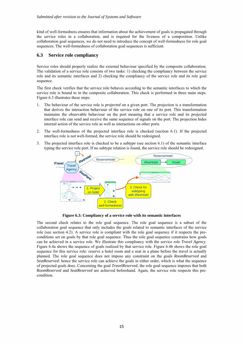
The first check verifies that the service role behaves according to the semantic interfaces to which the service role is bound to in the composite collaboration. This check is performed in three main steps. Figure 6.3 illustrates these steps:
1. The behaviour of the service role is projected on a given port. The projection is a transformation that derives the interaction behaviour of the service role on one of its port. This transformation maintains the observable behaviour on the port meaning that a service role and its projected interface role can send and receive the same sequence of signals on the port. The projection hides internal action of the service role as well as interactions on other ports.
2. The well-formedness of the projected interface role is checked (section 6.1). If the projected interface role is not well-formed, the service role should be redesigned.
3. The projected interface role is checked to be a subtype (see section 6.1) of the semantic interface typing the service role port. If no subtype relation is found, the service role should be redesigned.
ReserveHotel
iHoteliTravel iResHotel
iResPlane
TravelAgency
√
ReserveHoteliResHotel
3. Check forsubtyping
with iResHotel
iTravelAgency_ResHotel
iHotel_statemachine
2. Checkwell-formedness
TravelAgency
1. Projecton hotel
ReserveHotel
iHoteliTraveliTravel iResHotel
iResHotel
iResPlane
iResPlane
TravelAgency
√
ReserveHoteliResHotel
3. Check forsubtyping
with iResHotel
iTravelAgency_ResHotel
iHotel_statemachine
2. Checkwell-formedness
TravelAgency
1. Projecton hotel
Figure 6.3: Compliancy of a service role with its semantic interfaces
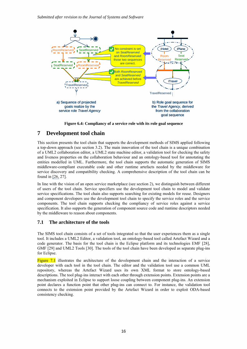
The second check relates to the role goal sequence. The role goal sequence is a subset of the collaboration goal sequence that only includes the goals related to semantic interfaces of the service role (see section 4.2). A service role is compliant with the role goal sequence if it respects the pre-conditions set on goals by that role goal sequence. Thus the role goal sequence constrains how goals can be achieved in a service role. We illustrate this compliancy with the service role Travel Agency. Figure 6.4a shows the sequence of goals realized by that service role. Figure 6.4b shows the role goal sequence for this service role: reserve a hotel room and a seat in a plane before the travel is actually planned. The role goal sequence does not impose any constraint on the goals RoomReserved and SeatReserved: hence the service role can achieve the goals in either order, which is what the sequence of projected goals does. Concerning the goal TravelReserved, the role goal sequence imposes that both RoomReserved and SeatReserved are achieved beforehand. Again, the service role respects this pre-condition.
Submitted after revision to the Journal of Systems and Software
16
a) Sequence of projectedgoals realize by the
service role Travel Agency
b) Role goal sequence forthe Travel Agency, derived
from the collaborationgoal sequence
RoomReserved SeatReserved
SeatReserved RoomReserved
TravelReserved
iHotel iPlane
RoomReserved
SeatReserved
iTravel
TravelReserved
No constraint is seton SeatReserved
and RoomReserved:those two sequences
are correct.
Both RoomReservedand SeatReservedare achieved before
TravelReserved
a) Sequence of projectedgoals realize by the
service role Travel Agency
b) Role goal sequence forthe Travel Agency, derived
from the collaborationgoal sequence
RoomReservedRoomReserved SeatReservedSeatReserved
SeatReservedSeatReserved RoomReservedRoomReserved
TravelReservedTravelReserved
iHotel iPlane
RoomReserved
SeatReserved
iTravel
TravelReserved
No constraint is seton SeatReserved
and RoomReserved:those two sequences
are correct.
Both RoomReservedand SeatReservedare achieved before
TravelReserved
Figure 6.4: Compliancy of a service role with its role goal sequence
7 Development tool chain
This section presents the tool chain that supports the development methods of SIMS applied following a top-down approach (see section 3.2). The main innovation of the tool chain is a unique combination of a UML2 collaboration editor, a UML2 state machine editor, a validation tool for checking the safety and liveness properties on the collaboration behaviour and an ontology-based tool for annotating the entities modelled in UML. Furthermore, the tool chain supports the automatic generation of SIMS middleware-compliant executable code and other runtime artefacts needed by the middleware for service discovery and compatibility checking. A comprehensive description of the tool chain can be found in [26, 27].
In line with the vision of an open service marketplace (see section 2), we distinguish between different of users of the tool chain. Service specifiers use the development tool chain to model and validate service specifications. The tool chain also supports searching for existing models for reuse. Designers and component developers use the development tool chain to specify the service roles and the service components. The tool chain supports checking the compliancy of service roles against a service specification. It also supports the generation of component source code and runtime descriptors needed by the middleware to reason about components.
7.1 The architecture of the tools
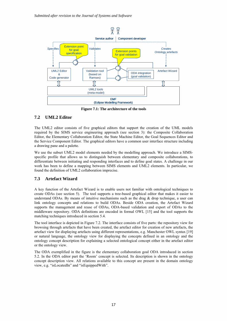
The SIMS tool chain consists of a set of tools integrated so that the user experiences them as a single tool. It includes a UML2 Editor, a validation tool, an ontology-based tool called Artefact Wizard and a code generator. The basis for the tool chain is the Eclipse platform and its technologies EMF [28], GMF [29] and UML2 Tools [30]. The tools of the tool chain have been developed as separate plug-ins for Eclipse.
Figure 7.1 illustrates the architecture of the development chain and the interaction of a service developer with each tool in the tool chain. The editor and the validation tool use a common UML repository, whereas the Artefact Wizard uses its own XML format to store ontology-based descriptions. The tool plug-ins interact with each other through extension points. Extension points are a mechanism exploited in Eclipse to support loose coupling between component plug-ins. An extension point declares a function point that other plug-ins can connect to. For instance, the validation tool connects to the extension point provided by the Artefact Wizard in order to exploit ODA-based consistency checking.
Submitted after revision to the Journal of Systems and Software
17
UML2 Editor&
Code generator
Artefact Wizard
UML2 tools(meta-model)
Validation tool(based on Ramses)
ODA integration(goal validation)
Extension points for goal validation
Extension point for goal
specification
EMF(Eclipse Modelling Framework)
Specifies Validates CreatesOntology artefacts
Component developerService author
UML2 Editor&
Code generator
Artefact Wizard
UML2 tools(meta-model)
Validation tool(based on Ramses)
Validation tool(based on Ramses)
ODA integration(goal validation)ODA integration(goal validation)
Extension points for goal validation
Extension point for goal
specification
EMF(Eclipse Modelling Framework)
Specifies Validates CreatesOntology artefacts
Component developerService author
Figure 7.1: The architecture of the tools
7.2 UML2 Editor
The UML2 editor consists of five graphical editors that support the creation of the UML models required by the SIMS service engineering approach (see section 3): the Composite Collaboration Editor, the Elementary Collaboration Editor, the State Machine Editor, the Goal Sequences Editor and the Service Component Editor. The graphical editors have a common user interface structure including a drawing pane and a palette.
We use the subset UML2 model elements needed by the modelling approach. We introduce a SIMS-specific profile that allows us to distinguish between elementary and composite collaborations, to differentiate between initiating and responding interfaces and to define goal states. A challenge in our work has been to define a mapping between SIMS elements and UML2 elements. In particular, we found the definition of UML2 collaboration imprecise.
7.3 Artefact Wizard
A key function of the Artefact Wizard is to enable users not familiar with ontological techniques to create ODAs (see section 5). The tool supports a tree-based graphical editor that makes it easier to understand ODAs. By means of intuitive mechanisms such as the drag & drop technique, a user can link ontology concepts and relations to build ODAs. Beside ODA creation, the Artefact Wizard supports the management and reuse of ODAs, ODA-based validation and export of ODAs to the middleware repository. ODA definitions are encoded in formal OWL [15] and the tool supports the matching techniques introduced in section 5.4.
The tool interface is depicted in Figure 7.2. The interface consists of five parts: the repository view for browsing through artefacts that have been created, the artefact editor for creation of new artefacts, the artefact view for displaying artefacts using different representations, e.g. Manchester OWL syntax [19] or natural language, the ontology view for displaying the concepts defined in an ontology and the ontology concept description for explaining a selected ontological concept either in the artefact editor or the ontology view.
The ODA exemplified in the figure is the elementary collaboration goal ODA introduced in section 5.2. In the ODA editor part the ‘Room’ concept is selected. Its description is shown in the ontology concept description view. All relations available to this concept are present in the domain ontology view, e.g. “isLocatedIn” and “isEquippedWith”.
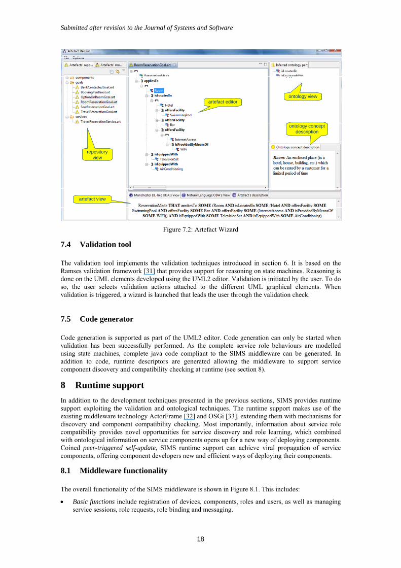
Submitted after revision to the Journal of Systems and Software
18
repository view
artefact editorontology view
ontology concept description
artefact view
repository view
artefact editorontology view
ontology concept description
artefact view
Figure 7.2: Artefact Wizard
7.4 Validation tool
The validation tool implements the validation techniques introduced in section 6. It is based on the Ramses validation framework [31] that provides support for reasoning on state machines. Reasoning is done on the UML elements developed using the UML2 editor. Validation is initiated by the user. To do so, the user selects validation actions attached to the different UML graphical elements. When validation is triggered, a wizard is launched that leads the user through the validation check.
7.5 Code generator
Code generation is supported as part of the UML2 editor. Code generation can only be started when validation has been successfully performed. As the complete service role behaviours are modelled using state machines, complete java code compliant to the SIMS middleware can be generated. In addition to code, runtime descriptors are generated allowing the middleware to support service component discovery and compatibility checking at runtime (see section 8).
8 Runtime support
In addition to the development techniques presented in the previous sections, SIMS provides runtime support exploiting the validation and ontological techniques. The runtime support makes use of the existing middleware technology ActorFrame [32] and OSGi [33], extending them with mechanisms for discovery and component compatibility checking. Most importantly, information about service role compatibility provides novel opportunities for service discovery and role learning, which combined with ontological information on service components opens up for a new way of deploying components. Coined peer-triggered self-update, SIMS runtime support can achieve viral propagation of service components, offering component developers new and efficient ways of deploying their components.
8.1 Middleware functionality
The overall functionality of the SIMS middleware is shown in Figure 8.1. This includes:
Basic functions include registration of devices, components, roles and users, as well as managing service sessions, role requests, role binding and messaging.
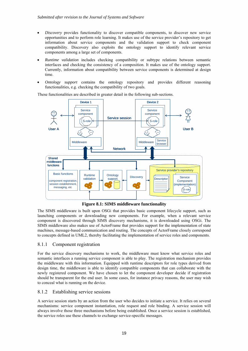
Submitted after revision to the Journal of Systems and Software
19
Discovery provides functionality to discover compatible components, to discover new service opportunities and to perform role learning. It makes use of the service provider’s repository to get information about service components and the validation support to check component compatibility. Discovery also exploits the ontology support to identify relevant service components among a large set of components.
Runtime validation includes checking compatibility or subtype relations between semantic interfaces and checking the consistency of a composition. It makes use of the ontology support. Currently, information about compatibility between service components is determined at design time.
Ontology support contains the ontology repository and provides different reasoning functionalities, e.g. checking the compatibility of two goals.
These functionalities are described in greater detail in the following sub-sections.
Sharedmiddlewarefunctions
Service provider’s repository
Device 1
Servicecomponent
S-role
Middleware
Device 2
Servicecomponent
S-role
ServiceComponent
(implementation)
S-role
Basic functions
component registration,session establishment,
messaging, etc
DescriptorOntologysupport
Runtimevalidation
Discovery
Network
Service session
User A User B
MiddlewareServicebrowser
Sharedmiddlewarefunctions
Service provider’s repository
Device 1
Servicecomponent
S-roleS-role
Middleware
Device 2
Servicecomponent
S-roleS-role
ServiceComponent
(implementation)
S-role
ServiceComponent
(implementation)
S-roleS-role
Basic functions
component registration,session establishment,
messaging, etc
DescriptorDescriptorOntologysupport
Ontologysupport
RuntimevalidationRuntimevalidation
DiscoveryDiscovery
Network
Service session
User A User B
MiddlewareServicebrowser
Figure 8.1: SIMS middleware functionality
The SIMS middleware is built upon OSGi that provides basic component lifecycle support, such as launching components or downloading new components. For example, when a relevant service component is discovered through SIMS discovery mechanisms, it is downloaded using OSGi. The SIMS middleware also makes use of ActorFrame that provides support for the implementation of state machines, message-based communication and routing. The concepts of ActorFrame closely correspond to concepts defined in UML2, thereby facilitating the implementation of service roles and components.
8.1.1 Component registration
For the service discovery mechanisms to work, the middleware must know what service roles and semantic interfaces a running service component is able to play. The registration mechanism provides the middleware with this information. Equipped with runtime descriptors for role types derived from design time, the middleware is able to identify compatible components that can collaborate with the newly registered component. We have chosen to let the component developer decide if registration should be transparent for the end user. In some cases, for instance privacy reasons, the user may wish to conceal what is running on the device.
8.1.2 Establishing service sessions
A service session starts by an action from the user who decides to initiate a service. It relies on several mechanisms: service component instantiation, role request and role binding. A service session will always involve those three mechanisms before being established. Once a service session is established, the service roles use these channels to exchange service-specific messages.
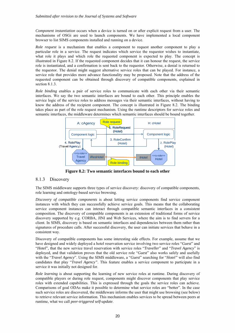
Submitted after revision to the Journal of Systems and Software
20
Component instantiation occurs when a device is turned on or after explicit request from a user. The mechanisms of OSGi are used to launch components. We have implemented a local component browser to list SIMS components installed and running on a device.
Role request is a mechanism that enables a component to request another component to play a particular role in a service. The request indicates which service the requestor wishes to instantiate, what role it plays and which role the requested component is expected to play. The concept is illustrated in Figure 8.2. If the requested component decides that it can honour the request, the service role is instantiated, and a confirmation is sent back to the requestor. Otherwise, a denial is returned to the requestor. The denial might suggest alternative service roles that can be played. For instance, a service role that provides more advance functionality may be proposed. Note that the address of the requested component can be obtained through discovery of compatible components, explained in section 8.1.3.
Role binding enables a pair of service roles to communicate with each other via their semantic interfaces. We say the two semantic interfaces are bound to each other. This principle enables the service logic of the service roles to address messages via their semantic interfaces, without having to know the address of the recipient component. The concept is illustrated in Figure 8.2. The binding takes place as part of the role request mechanism. Using the runtime descriptors for service roles and semantic interfaces, the middleware determines which semantic interfaces should be bound together.
Component logic
A: cAgency H: cHotel
1. RoleRequest(Hotel)
3. RoleConfirm(Hotel)
<<s-role>>TravelAgency
<<s-role>>HoteliHoteliResHotel
Component logic
Role binding
Role request
2. RolePlay(Hotel)
Component logic
A: cAgency H: cHotel
1. RoleRequest(Hotel)
3. RoleConfirm(Hotel)
<<s-role>>TravelAgency
<<s-role>>HoteliHoteliResHotel
Component logic
Role binding
Role request
2. RolePlay(Hotel)
Figure 8.2: Two semantic interfaces bound to each other
8.1.3 Discovery
The SIMS middleware supports three types of service discovery: discovery of compatible components, role learning and ontology-based service browsing.
Discovery of compatible components is about letting service components find service component instances with which they can successfully achieve service goals. This means that the collaborating service component instances can interact through compatible semantic interfaces in a consistent composition. The discovery of compatible components is an extension of traditional forms of service discovery supported by e.g. CORBA, JINI and Web Services, where the aim is to find servers for a client. In SIMS, discovery is based on semantic interfaces and dependencies between them rather than signatures of procedure calls. After successful discovery, the user can initiate services that behave in a consistent way.
Discovery of compatible components has some interesting side effects. For example, assume that we have designed and widely deployed a hotel reservation service involving two service roles “Guest” and “Hotel”, that the new service travel reservation with service roles “Traveller” and “Travel Agency” is deployed, and that validation proves that the old service role “Guest” also works safely and usefully with the “Travel Agency”. Using the SIMS middleware, a “Guest” searching for “Hotel” will also find candidates that play “Travel Agency”. This feature enables a service component to participate in a service it was initially not designed for.
Role learning is about supporting the learning of new service roles at runtime. During discovery of compatible players or during role request, components might discover components that play service roles with extended capabilities. This is expressed through the goals the service roles can achieve. Comparisons of goal ODAs make it possible to determine what service roles are “better”. In the case such service roles are discovered, the middleware informs the user that might use browsing (see below) to retrieve relevant service information. This mechanism enables services to be spread between peers at runtime, what we call peer-triggered self-update.
Submitted after revision to the Journal of Systems and Software
21
Ontology-based service browsing enables the user to search for new components. Browsing is initiated by the user and exploits information about specify device types and user preferences. The user specifies a set of desirable features. That specification is transformed in an ODA that is used by the middleware ontology support to identify service components with matching ODAs. The user can then browse through the list of identified components and retrieve their descriptions. The component descriptions are currently supplied by the component developer at design time. Alternatively they could be derived based on the component ODAs; this is an issue of future work. During browsing, the user can select the service components to be installed.
8.2 Using ontology driven artefacts at runtime
Beyond design time, the ontology driven artefacts (ODAs) and ontology-based techniques introduced in section 5.4 can also be exploited at runtime. The main application of ODAs at runtime relates to ontology-based service browsing. This functionality requires several underlying ontology techniques such as querying for services based on features, filtering upon user preferences and compatibility checking between components and devices. Another application of ODAs goes on behind the scene: the middleware exploits the ontology support to create relations between components by comparing their goals. These relations are then exploited to provide role learning support.
Most of the ODAs used at runtime are built at design time. The ontology runtime repository stores ODAs in the same form as defined at design time. Each ODA is defined as an ontology class stored in an OWL file. Some ODAs are built at runtime, like the ODAs representing user queries and user preferences. Service ODAs, component ODAs and device ODAs are ODA types that can be built for queries. ODAs are directly generated as OWL classes when being specified at runtime, and can thus be processed right away using the underlying ontology techniques.
The ODAs built at runtime use the terminology from the service domain ontology, and their structure follows the ODA meta-model. In that way, they are comparable with the ODAs defined at design time. For instance, a user preference is a class of services with specific features preferred or required by the user. In the case the user preference specifies that encryption is required, the services that do not provide encryption are filtered out during service discovery.
8.3 Validation at runtime
The most straightforward approach for guaranteeing compatibility of runtime compositions is to make decisions about what components can play in a service at design time, and to instantiate services adhere accordingly at runtime. This is an efficient approach at the cost of flexibility. An alternative approach is to perform provide advanced reasoning support to determine all potential compositions and validate them at runtime. This is a flexible approach at the cost of performance. We propose a mixed approach where models of service composition variants are available at runtime. This means that constraints are set on the service composition, but different compositions are allowed.
Different collaboration patterns may support users in achieving specific goals. For instance, a Traveller service can be connected directly to the Hotel and Plane service roles, or it can be connected to a Travel Agency service role (itself connected to Hotel and Plane service roles). We propose to represent these different collaboration patterns using collaboration frameworks and to exploit these frameworks at runtime to identify compositions of services roles that can interact together in a correct way. A collaboration framework specifies the service role types involved in the service collaboration, the relations between these types and the goal sequences that can be achieved in the service. A service role type is characterized by a set of semantic interfaces. A service is thus instantiated through the plugging of service role instances compliant to the types defined in a framework. The concept of collaboration framework is similar to component frameworks introduced by [34]. Composition frameworks are defined at design time. When a composition that fits a framework is found at runtime, some validation is still needed: the service role goal sequences should be consistent and the dependency graph should not contain any loop (see section 6.2.1). The validation techniques used at design time can be applied at runtime [11].
The current middleware implementation exploits compatibility and subtyping information derived from design time. This information is stored in the service provider repository. It is possible to deduce subtyping and compatibility relations from existing ones, as subtyping is a transitive relation. Collaboration frameworks were not implemented, due to the lack of resources.
Submitted after revision to the Journal of Systems and Software
22
9 Lessons Learned from Case Study
The assessment of the feasibility and adequacy of the SIMS engineering framework was undertaken by a case study at Gintel, a telecom software vendor. The methodology, tools and middleware were evaluated. In this section we explain the goals of the assessment and summarize the obtained results.
9.1 Goals of the assessment
The case study sought to answer a number of questions concerning the SIMS approach: i) the cost of introducing the approach in an organisation, ii) the benefits of the validation approach in finding behavioural errors early, iii) the cost of annotating components with ODAs, and finally iv) the combination of ontologies. The benefits of the approach in a setting with multiple stakeholders could not be assessed, as only one component developer was involved, and no software market place existed.
9.2 The trial service
The trial service developed for the assessment was from the transport delivery domain: a collaborative courier service, named cCourier. The service supports package delivery, and involves multiple users: a company that organises package delivery, customers who wish to place deliveries, places that represent destinations where packages can be picked up and delivered, and drivers who perform deliveries. Features include placing an order, selecting a driver, picking up and delivering a package, tracing a package, and chatting between drivers and places. The development required the specification of multiple service roles representing the different users involved, and the specification of multiple collaborations between these roles. The chat feature was developed in variants (with and without support for multimedia messaging) to allow an assessment of role learning.
9.3 The evaluation process
The cCourier service was designed using the top-down development process in Figure 3.2, since the service was developed from scratch. The evaluation process lasted for a period of 12 weeks, involving 4 people working half time. The work carried out during this period ranged from reading and getting familiar with the SIMS methodology, using the different tools, executing the developed services and discussing results in a post mortem. The work was conducted in close co-operation with the technology providers of the project; this was necessary as the tool chain was still immature.
None in the assessment team had prior knowledge of the theory developed in SIMS. The team was given the development guidelines developed within the project [14], in addition to a one-day introduction course and on-site support from one of the technology providers the first two days.
The assessment was lead by an experienced software engineer. The remaining members consisted of an experienced developer with a strength in programming (not modelling), and two juniors in their last year of MSc study, both eager programmers. All had an education background in telematics and were familiar with the concepts of reactive systems and state machine-based modelling.
A main requirement to the evaluation team was to assess the distinguishing features of the approach, such as creating dual semantic interfaces, checking for compatibility, adding ODAs and exploiting role learning. The validation features were utilized, among them detection and elimination of errors concerning mixed-initiatives, checking the compatibility of semantic interfaces, checking compliancy between semantic interfaces and service roles, and role learning.
The tools used were prototypes, and the evaluation team used a large part of their time reporting bugs in the tools and communicating with tool developers. These issues were factored out by the metrics collected. Details of the assessment process and metrics collected can be found in [35].
9.4 Results
The assessment has shown the feasibility of the SIMS engineering approach to model, implement and execute simple service components. Although the tool chain was unstable when the assessment started, it was capable of supporting the development methodology. Also the middleware support for service instantiation, discovery and browsing worked well. The results are summarised in the following table.
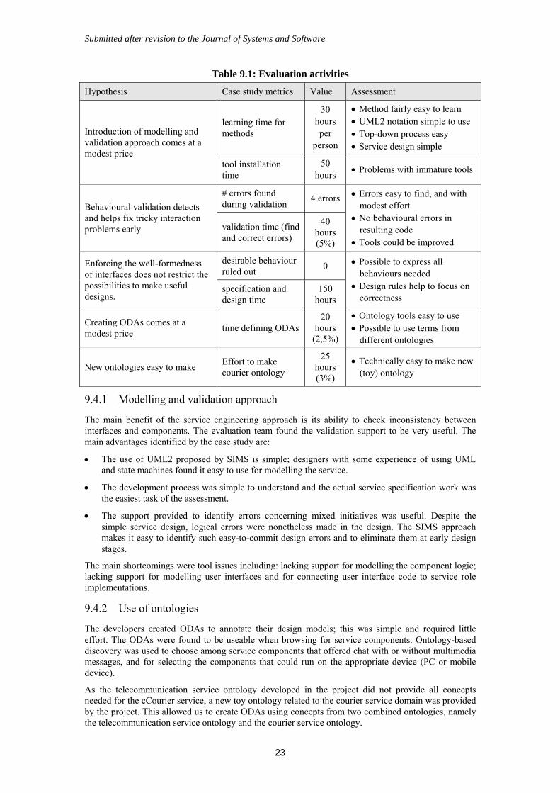
Submitted after revision to the Journal of Systems and Software
23
Table 9.1: Evaluation activities
Hypothesis Case study metrics Value Assessment
learning time for methods
30 hours per
person
Method fairly easy to learn UML2 notation simple to use Top-down process easy Service design simple
Introduction of modelling and validation approach comes at a modest price
tool installation time
50 hours
Problems with immature tools
# errors found during validation
4 errors Behavioural validation detects and helps fix tricky interaction problems early validation time (find
and correct errors)
40 hours (5%)
Errors easy to find, and with modest effort
No behavioural errors in resulting code
Tools could be improved
desirable behaviour ruled out
0 Enforcing the well-formedness of interfaces does not restrict the possibilities to make useful designs.
specification and design time
150 hours
Possible to express all behaviours needed
Design rules help to focus on correctness
Creating ODAs comes at a modest price
time defining ODAs 20
hours (2,5%)
Ontology tools easy to use Possible to use terms from
different ontologies
New ontologies easy to make Effort to make courier ontology
25 hours (3%)
Technically easy to make new (toy) ontology
9.4.1 Modelling and validation approach
The main benefit of the service engineering approach is its ability to check inconsistency between interfaces and components. The evaluation team found the validation support to be very useful. The main advantages identified by the case study are:
The use of UML2 proposed by SIMS is simple; designers with some experience of using UML and state machines found it easy to use for modelling the service.
The development process was simple to understand and the actual service specification work was the easiest task of the assessment.
The support provided to identify errors concerning mixed initiatives was useful. Despite the simple service design, logical errors were nonetheless made in the design. The SIMS approach makes it easy to identify such easy-to-commit design errors and to eliminate them at early design stages.
The main shortcomings were tool issues including: lacking support for modelling the component logic; lacking support for modelling user interfaces and for connecting user interface code to service role implementations.
9.4.2 Use of ontologies
The developers created ODAs to annotate their design models; this was simple and required little effort. The ODAs were found to be useable when browsing for service components. Ontology-based discovery was used to choose among service components that offered chat with or without multimedia messages, and for selecting the components that could run on the appropriate device (PC or mobile device).
As the telecommunication service ontology developed in the project did not provide all concepts needed for the cCourier service, a new toy ontology related to the courier service domain was provided by the project. This allowed us to create ODAs using concepts from two combined ontologies, namely the telecommunication service ontology and the courier service ontology.
Submitted after revision to the Journal of Systems and Software
24
9.4.3 Validity of assessment
The assessment of SIMS was limited to a single organisation over a short period of time (4 people for 12 weeks working half their time on the assessment, with a total of 835 hours of effort). The metrics were based on status reports filled in by the evaluation team members at the end of each evaluation day.
The positive results regarding the usefulness of the methods for modelling, validating and using ontologies are based on the viewpoints of the people involved. On the downside were challenges due to immature tools and platform problems, as can be expected when research projects provide tools and middleware solutions. Care was taken to single these factors out during the assessment.
Regarding the combination of ontologies, the toy ontology for the courier service only took 2-3 days to develop, complete with analysis of the domain, implementation in Protégé, and integration with the SIMS telecoms ontology. However, merging an existing third-party ontology could be very demanding. This issue is discussed in [17].
10 Related Work
In this section, we compare the work of SIMS to other representative and related efforts. As our work provides a comprehensive solution to service modelling and validation, we cover a number of research topics. We first consider other model-driven service engineering approaches, and note that they mainly focus on consumer-provider services, not on collaborative services. Significant in our approach are the concepts of goal and role. Although they are not specific to our approach, few software engineers seem to be familiar with them. In sections 10.2 and 10.3, we explain how we relate to other uses of these concepts. After discussing the overall approach and the concepts, we go through the main techniques in our approach. In sections 10.3 and 10.4 we consider ontology-based techniques and behavioural compatibility checking in the context of software engineering. Then, in sections 10.5 and 10.6, we narrow the scope to service engineering and discuss service discovery and service composition. Service discovery and composition have received much attention in the web service domain. Some techniques exploit ontologies for describing services, but the formalisation of the behavioural semantics of services and their compositions has been neglected, unlike in our approach.
10.1 Model-driven service engineering
The service engineers, the people who create service logic, can fulfil narrow time and cost constraints only if they have access to powerful development tools supporting efficient modelling, consistency checking, validation, and automated code generation. Nonetheless, industrial service engineering is still largely implementation-oriented without any clear separation between service logic and implementation detail. Service logic is often developed by coding more or less directly in terms of platforms such as Java EE [36] or Web Services [37], resulting in platform dependency, low portability, and, for client–server platforms, a somewhat restricted range of service functionality. This is a paradox, since service orientation essentially means focusing on service functionality and hiding implementation details. In the model-driven architecture, one strongly argues the case for developing platform-independent models that are transformed into alternative implementations, more or less automatically [38]. This understanding is a driving force in SIMS.
Model driven approaches to service engineering are still in their infancy. Most of the approaches developed for service modelling focus on consumer-provider services, and not on collaborative services (see section 3.2). This is the case of SOAD (Service Oriented Analysis and Design [39]) that was developed by IBM. The idea was to combine OOAD (Object-Oriented Analysis and Design), EA (Enterprise Architecture) and BPM (Business Process Modelling) in a hybrid approach in order to support SOA deployment. This idea was further developed in SOMA (Service Oriented Modelling and Architecture [40]), where services, flows and components realizing services are identified. SOMA adopts a more traditional SOA approach taking into account business dimensions: it makes a clear separation between providers and consumers, while services are exposed to business partners for composition. The methodology describes a business-driven top-down approach, combined with and IT-based bottom-up approach (where existing services can be reused). The SOMA was later combined with the Rational Unified Process (RUP) [41] to give birth to RUP for SOA. RUP is an iterative methodology defining active phases (actions to perform) and passive phases (artefacts, areas and roles involved). Different stages cover the whole life cycle of a project, from the business modelling to the implementation, with side aspects like management and environment. Hence RUP for SOA, presented
Submitted after revision to the Journal of Systems and Software
25
as a plug-in in Rational Method Composer [42], is seen as RUP augmented with Service-Oriented content. It covers a broader domain than ours, particularly on business issues.
Similarly to us, several of UML-based approaches for service modelling exploit the concept of UML2 collaborations. Kramler & al. [43] propose to use UML2 collaborations for modelling web service collaboration protocols, and activity and interaction diagrams for more detailed specification. Closer to our approach, Kraemer and Herrmann [44] specify reactive systems with UML2 collaborations for structural properties, and UML2 activities for behavioural aspects. However, the authors focus on design time, while we take advantage of service goals to discover useful compositions and compatibility relations to check composition consistency at runtime. Also Ermagan and Krüger [45] consider services to be collaborations between roles. They introduce a UML2 profile for the specification of service-oriented architectures. However they do not seem to exploit the capability of composition of collaborations (i.e. using UML2 collaboration uses). The definition of a UML Profile and Metamodel for services (SoaML) is an OMG specification in its finalization phase [46]. The SIMS project has contributed to this work, and has especially the influenced the introduction of the Milestone concept (this corresponds to the SIMS role goal concept). The Milestone concept represents something quite new in the UML domain as milestones are concepts that are not functionally necessary, but still has an operational definition. Structural modelling in SoaML and SIMS are similar. SoaML service contracts correspond to SIMS elementary collaborations, and service architectures to composite collaborations. SoaML does not provide guidelines for behaviour specification, which SIMS does.
In terms of modelling of collaborations, we might also consider interaction diagrams such as the ITU-T MSC language in 1994 [47]. However, interactions alone do not really cover structural aspects nor provide flexible binding of interfaces to roles in the way now made possible using UML2 collaborations. While interaction diagrams provide a cross-cutting view of a service, they become often too fragmented or too detailed to be easily understood. Our approach abstracts the cross-cutting view on the service using collaborations and goal sequences, and describes the detailed behaviour of interfaces using state machines.
10.2 The concept of goals
Goals have been extensively used in the engineering domain to capture, analyze, validate and document the properties a system should have [48, 49]. Similarly goals are proposed in service modelling to represent the properties desired by the user [50, 51]. While the term goal is a concept related to the user, capability is used in relation with the service and represents what the service does. In their conceptual service framework Quartel & al. [50] suggest that the definition of the user goal should provide a high-level description of the service, this to facilitate the discovery of services. They propose an abstraction level at which a service is modelled as a single interaction, that somehow matches an elementary collaboration in our work. However, these approaches to goal orientation do not seem to be concerned with interaction behaviour between distributed cooperating components. To the best of our knowledge, no one has used goal sequences before to represent the overall functionality of services and the dependencies between elementary collaborative behaviours.
Goals associated to components and represented in the state machines are similar to progress labels introduced by Holzmann [52] and can be exploited to validate the liveness properties of interacting state machines. Related to our work and also building upon on [3], Castejón and Bræk extend the concept of goal sequences allowing the unambiguous specification of services solely using collaborations and goal sequences (but not state machines) [53]. Their aim is to develop abstract service models that can be used for early detection of errors, such as implied scenarios. Their approach focuses on service composition at design time. Differently we consider discovery and composition at runtime and therefore need more simple service representations.
10.3 The concept of roles
The role concept was introduced at the end of the 70’s in the context of data modelling [54] and emerged again in the object-oriented literature. Using roles for functional modelling of collaborations was of primary concern in the OORAM methodology [55], and was one of the inputs influencing the UML work on collaborations in the OMG. Within tele-service engineering it has been a long-standing convention to describe telephone services using role names like A and B or caller and callee. The concept of service role in SIMS both stems from OORAM and the telecom tradition.
Submitted after revision to the Journal of Systems and Software
26
In [56], Bræk classified different uses of the role concept, and pointed out that UML1 was too restrictive, since a Classifier-Role could bind to only one classifier, and was not an independent concept that could be re-used by different classes. As part of collaborations UML2 introduces flexible binding of classifiers to collaboration roles. SIMS exploits this when binding service roles to semantic interfaces allowing reuse of semantic interfaces and components to service roles.
10.4 Ontology-based techniques
The application of ontologies in SIMS is an original merge of different kinds of ontology-based techniques. Using the classification proposed in the survey of ontologies’ applications in software engineering [57], we cover both ontology-enabled development (at design time) and ontology-enabled architecture (at runtime). An ODA that describes a kind of a resource is expressed as an OWL class. A similar approach is used in Semantic Web Services [58, 59]. An alternative is to describe resources as OWL individuals [60]. The class-based approach allows us to exploit a variety of class constructs defined in OWL. In that way more expressive and precise descriptions of resources can be described than when using individuals. The ODA class is a complex structure that is constructed by combining basic concepts from a domain ontology. It extends our previous work presented in [61].
Benefits from ontology-enabled development have been collected by Deridder and Wouters [62] who point out that using a precise terminology defined in an ontology to annotate software entities overcomes the ambiguity of the programming and modelling languages. This is especially beneficial in the case of complex services and large service systems, where component development usually involves different developers. Happel and others [63] present how software artefacts with especially focus on software libraries can be easily reused if properly annotated with ontologies. The authors exploit ontology-based queries as a flexible and powerful means to acquire desirable information. In our approach, we support reuse in a similar way with queries represented using ODAs. Using ontologies in software engineering is addressed by the W3C in [64]. Several use cases described in the W3C document (e.g., “Software Lifecycle Support”) are covered in our approach.
10.5 Checking behavioural compatibility
Our validation approach is based partial techniques that were initially proposed by authors of this paper in separate works [25, 65]. Our work extends these results aiming at a tight integration of the validation approach in the development process and at a simplification of the validation concepts and their alignment with the modelling concepts. The extraction of interface dependencies and the validation of liveness properties were developed in SIMS.
Proving the absence of deadlock when assembling components is a difficult task. The work closest to our idea of semantic interface dependencies is, to our knowledge, the one of [66]. The authors have the interesting approach to specify compositions using Open Petri Nets (i.e. Petri Nets extended with input and output places). They are able to detect deadlock configurations. However, their work is focused on service trees, where components may invoke other components and wait for their answer, hence producing a service tree. Our component model is more flexible, as we allow components to coordinate their behaviour in a collaborative manner. This allows more complex composition patterns.
10.6 Service discovery
Service discovery is usually defined as the capability to discover services offered by software components in a network. It covers description of services, registration of service descriptions of deployed services and querying for deployed services satisfying the description of a needed service. The discovery of compatible component instances in our approach covers these mechanisms. As component instances are entities that can be managed by different parties, it is suitable to compare this kind of discovery with service discovery in contemporary SOA. Additionally to traditional service discovery, our approach provides support for learning new behaviours (see section 8.1).
In the web service domain, intensive research work aims at the automation of service discovery and composition. Basis web technologies based on WSDL [67] operate at a syntactic level and therefore require human interaction. The semantic Markup for Web Services (OWL-S) [68] and the Web Service Modeling Ontology (WSMO) [51] are results of that research effort. OWL-S is a widely used approach for service semantic modelling, which consists of a set of ontologies for describing services and reasoning over these descriptions. OWL-S consists of three levels. First, the Service Profile provides a
Submitted after revision to the Journal of Systems and Software
27
human readable description of the functional aspects of the service by specifying its inputs and outputs, information about the service provider, a quality rating, and other attributes used for service discovery. Second, the Service Model describes the service's operations including the sets of inputs, outputs, pre-conditions and results of the service execution. Finally, the Service Grounding deals with implementation details such as communication protocol, message formats, and port numbers. OWL-S lacks a formal specification of a logical formalism to define rules and logical expressions, in particular for describing relations of inputs and outputs or preconditions and postconditions respectively [69]. WSMO is a framework for semantic descriptions of Web Services and acts as a meta- model for services based on the Meta Object Facility (MOF) [70]. Four elements are defined for the description of Web Services. First, ontologies provides the concepts and relationships used by the other three elements. Second, goals define the user objectives and expectations from the Web Services. Third, Web Service descriptions define service capabilities. Capabilities include the semantic description of a variety of properties such as non-functional properties (e.g. financial or security aspects), pre- and post-conditions and interface behaviours. Finally, mediators aim at solving all the interoperability problems that arise. Although detailed service descriptions are needed for a precise service discovery, unlike our goals WSMO does not provide any abstract description of services that would facilitate a quick initial discovery of potential, relevant services. The detailed interface behaviours, called choreographies in WSMO, are described using UML state machines in our work. We have intentionally avoided replication between UML models and ontology artefacts. We do not define the semantics of each message using ontologies, but this could be done in the same way as for goals.
Related to the quality of service discovery, Klein and Bernstein [71] propose a process-based approach based on service behaviour description. Their aim is to provide techniques that support a higher level of precision than traditional techniques, i.e. matching the real user needs. They claim to obtain better results than in concept-based approaches that make use of ontologies. Although they focus on services as defined in client-server architectures, this result is of interest with respect to discovery of compatible components in SIMS. Discovery in SIMS combines the concept-based and behaviour-based approaches. Collaboration goals can be expressed using ontologies, and thus are appropriate for concept-based discovery approaches. Discovery based on semantic interface descriptions are similar to process-based discovery.
10.7 Service composition
Service composition is usually defined as the capability to combining several simple services into a more complex service. It covers languages to describe compositions, platform support for the selection of suitable instances for the participating services and mechanisms for binding services together. Thomas Erl distinguishes between two types of composition: service orchestration and choreography, where the coordination of a composition is centralized in orchestration and distributed in choreography [12]. This view is also followed by WS-CDL [72]. It differs however from other views, e.g., in WSMO [51], where choreography refers to the Web service interface defining message exchanged when a user consumes the service. SoaML [46] also considers choreography to be a specification of what is transmitted between parties. A service in our approach can be considered as a choreography of component instances according to the definition of choreography proposed by Erl.
WS-CDL is the representative choreography language defined by W3C. The main criticism of WS- CDL is its lack of formal grounding [73]. Several works have extended WS-CDL with formal semantic, for example, by modelling WS-CDL specifications using the Pi-calculus [74] or FSP process algebra [75]. Validation and verification is then performed through the use of formal process model checking techniques. For example, [75] is based on FSP process algebra for verification of deadlock free and other safety properties such as obligations. These approaches however are not applicable at runtime. They do not either have equivalent methods for liveness validation in the way that goals and goal sequences do in our approach.
It is also typical to consider orchestration as local view of a single service and choreography as global view of multiple interacting services [75, 76]. An effective engineering approach is to define the global description of choreography and then extract local description for each participant as orchestration. Such an approach is followed by [76, 77]. In [77], the translation based on endpoint projection is used to generate orchestrations from a given choreography, and conformance validation is the verification of process refinement between orchestrations. In addition, it claims that some conditions must be satisfied to realize local enforceability. [76] provides a similar approach to model choreography and to develop services based on such models. It defines choreography (global model) using Let’s Dance [78], a language derived from workflow and architecture description languages. It provides algorithms to
Submitted after revision to the Journal of Systems and Software
28
translate the global model to local model and focuses on validation of local enforceability of the global model. These existing approaches have not addressed the challenges of mixed initiatives. In addition, they focus mostly on translation from the global description to the local description and the conformance validation targeted on local enforceability of global specification. Our approach emphasizes the active role of a participant in the choreography and recognizes the challenges of mixed initiatives. It also provides mechanisms to specify and validate usefulness as expressed by goals and goal sequences.
11 Conclusions and Future Work
Today’s software is not solely developed by tightly collaborating development teams that have control over all parts of the system under development. Moreover the composition of software systems is no longer an activity that is solely performed at design time. Software composition is frequently performed at runtime in many kinds of systems and for various purposes such as ubiquitous computing and autonomic computing. Open source software initiatives and service-oriented architectures are enablers of these trends and contribute to the establishment of open development and runtime environments where software can be assembled out of independent reusable software units either at design time or at runtime. Open environments pose new challenges to component developers, service providers and end users. The SIMS project has addressed some of them: that of promoting and facilitating reuse of components, and that of guaranteeing compatibility of composed systems. To that end, SIMS has developed a comprehensive engineering framework that includes a model-driven development approach and runtime support and has shown the viability of the approach for the engineering of mobile services.
Considering the requirements listed in section 2, SIMS has achieved significant results:
We exploit ontologies to establish a common meaning of terms of a domain and provide ontology-based methods and tools to let developers describe or search for service entities. This is a foundation for open development and runtime environments where stakeholders can publish and share service artefacts.
We propose UML-based modelling techniques to specify services formally, and provide validation techniques in order to validate the service behaviour. This is a foundation for open development environments where service specifiers can share service specifications or parts of specifications.
We also use UML to describe formally the components that realize the services, and provide validation techniques in order to check compliancy between components and service specifications. This is a foundation for open development and runtime environments where components developers can create independent and reusable components, and users install components that behave consistently in a service.
We propose a runtime platform that supports discovery, deployment and consistency checking. SIMS runtime support can achieve viral propagation of service components, offering component developers new and efficient ways of deploying their components. This a foundation for open runtime environments where service providers can publish services and end users discover and install components, and then collaborate consistently in services.
Although the SIMS project has provided important foundations towards an open software marketplace, the full creation of the open marketplace itself was out of the scope of the project. For instance, we do not provide any infrastructure including repositories and associated mechanisms, e.g. business models, trust management and privacy management. We have sketched initial solutions to addresses scalability, but not performed any detailed scalability study.
Furthermore, since the goals and requirements of the SIMS project were introduced, new technology and platforms have been introduced additional requirements and opportunities. For example, the Android project is a relevant representation of an open development marketplace. Android does not address important service engineering activities, such as service modelling and validation, and could thus benefit from the SIMS results.
While the SIMS project had focus on service engineering techniques, three of the four organisations contributing to this article have recently started a new research project, UbiCompForAll [79], which addresses service composition from a user viewpoint. The idea is to exploit the foundations for service discovery, composition and validation to let non-IT professional users create and compose themselves
Submitted after revision to the Journal of Systems and Software
29
services. In this project the results of the SIMS project are exploited in a long-term and continuing research where we pursue the idea of open service environments even further.
ACKNOWLEDGEMENTS
The contributions of all members of the SIMS project consortium are gratefully acknowledged. SIMS was supported financially by the EU IST 6th framework programme under contract no. 027610. The Norwegian project UbiCompForAll and the EU IST project SHAPE have supported us in writing this paper.
REFERENCES
1. Medvidovic, N., Taylor R.N. A classification and Comparison Framework for Software Architecture Description Languages. In IEEE Transactions on Software Engineering, Vol. 26 (1), 2000, p. 70-93.
2. OMG. UML 2.0 Superstructure Specification, Revised Final Adopted Specification, ptc/04-10-02, Object Management Group, Needham (MA), USA, Oct. 8, 2004. 2004.
3. Sanders R.T., et al. Using UML 2.0 Collaborations for Compositional Service Specification. In proceedings of Model Driven Engineering Languages and Systems, 8th International Conference, MoDELS 2005. 2005. Montego Bay, Jamaica. Springer Berlin / Heidelberg. p. 460-475.
4. Sanders R.T.: Collaborations, semantic interfaces and service goals: a way forward for service engineering. Dr. Ing thesis, Norwegian University of Science and Technology (2007).
5. Castejón H.N, Bræk R. Formalizing Collaboration Goal Sequences for Service Choreography. In proceedings of Formal Techniques for Networked and Distributed Systems - FORTE 2006. 2006. Paris, France. Springer Berlin / Heidelberg. p. 275-291.
6. Kraemer F.A., Herrmann P. Service Specification by Composition of Collaborations--An Example. In proceedings of Web Intelligence and International Agent Technology Workshops, 2006. 2006. Hong Kong, China. IEEE. p. 129-133.
7. Deridder D., Wouters B. The use of ontologies as a backbone for software engineering tools. In proceedings of the Fourth Australian Knowledge Acquisition Workshop AKAW99, pp. 187-200, 1999.
8. Happel H.-J., Seedorf S., Applications of Ontologies in Software Engineering, 2nd International Workshop on Semantic Web Enabled Software Engineering (SWESE 2006), Athens, GA, USA, 2006.
9. SIMS Project Home Page, Semantic Interfaces for Mobile Services, www.ist-sims.org.
10. Wireless Mobile Data & Paging Communications Solutions, http://www.withpath.com/
11. Carrez, C. (ed.): SIMS Deliverable D2.2, Languages and methods guidelines, 2nd version. www.ist-sims.org. 2007.
12. Erl, T. Service-Oriented Architecture - Concepts, Technology, and Design. 6th ed. 2006. Prentice Hall.
13. Carrez, Cyril, Floch, Jacqueline and Sanders, Richard, “Describing component collaboration using goal sequences," In: Distributed Applications and Interoperable Systems, LNCS 5053/ 2008, Springer-Verlag GmbH, 2008.
14. Carrez, C. (ed.): SIMS Deliverable D2.3, SIMS Principles and Techniques for Service Engineering. www.ist-sims.org. 2008.
15. Bechhofer, S., F. van Harmelen, J. Hendler, I. Horrocks, D.L. McGuinness, P.F. Patel-Schneider, and L.A. Stein, OWL Web Ontology Language Reference. 2005.
16. R. Dawidziuk and P. Cieślak (eds): SIMS Deliverable D3.5: A Proof-of-concept ontology of telecommunications services, final version. 2008.
17. Michał Rój, (ed): SIMS Deliverable D3.7: Recommendations on developing telecommunications services ontology. 2008.
Submitted after revision to the Journal of Systems and Software
30
18. Michał Rój, (ed): SIMS Deliverable D3.4: Techniques for ontology driven semantic interface artefacts, final version. 2007.
19. Horridge, M., et al., The Manchester OWL Syntax, in In: Proc. of the OWL Experiences and Directions Workshop (OWLED’06) at the ISWC’06. 2006.
20. Li, L. and I. Horrocks, A software framework for matchmaking based on semantic web technology. International Journal of Electronic Commerce, 2004. 8(4): p. 39-60.
21. Paolucci, M., et al. Semantic Matching of Web Services Capabilities. in First International Semantic Web Conference on The Semantic Web. 2002.
22. Evren Sirin, Bijan Parsia, Bernardo Cuenca Grau, A. Kalyanpur, and Y. Katz. Pellet. A practical OWL-DL reasoner. In Journal of Web Semantics, 2006.
23. Alpern, B., Schneider, F.: Recognizing safety and liveness. Journal of Distributed Computing, vol. 2, pp. 117-126. Springer Berlin / Heidelberg (1987).
24. Floch, J., Bræk, R.: Using Projections for the Detection of Anomalous Behaviours. In: Reed, R., Reed, J. (eds) SDL 2003: System Design. LNCS, vol. 2078, pp. 251–268, Springer (2003).
25. Carrez, C.: Contrats Comportementaux pour Composants. Thesis, ENST, (2003).
26. Cyril Carrez, Lotte Johansen, Pawel Cieslak, Stefan Hänsgen: Service engineering with the SIMS design and validation tools. In Nordic Journal of Computing, vol. 14 (2008), pp. 245–263.
27. Hänsgen, S., Cieślak,P., Carrez, C. (ed.): SIMS Deliverable D4.3, Final Open Source Design Tool Components. www.ist-sims.org. 2008.
28. Eclipse Modelling Framework, http://www.eclipse.org/modeling/emf
29. Graphical Modelling Framework, http://www.eclipse.org/modeling/gmf
30. Eclipse UML2tools. http://www.eclipse.org/modeling/mdt/?project=uml2tools#uml2tools
31. Frank Alexander Kraemer: Arctis and Ramses: Tool Suites for Rapid Service Engineering. In: Norsk informatikkonferanse (NIK 2007), Nov. 19-21, Oslo.
32. Bræk, R. and Melby, G: Model-Driven Service Engineering. In: Model-Driven Software Development. Springer. 2005
33. OSGi Alliance, http://www.osgi.org
34. Szyperski, C. Component Software: Beyond Object-Oriented Programming. 2nd ed. 2002. Addison-Wesley. ISBN 0-201-74572-0.
35. Mazen Malek Shiaa (ed.): SIMS Deliverable D6.6, Evaluation of SIMS Approach. www.ist-sims.org. 2008.
36. Java Enterprise Edition. http://java.sun.com/javaee/
37. Web of service. http://www.w3.org/webofservices/
38. Mellor, S., Clark, A., Futagami, T.: Special Issue on Model-Driven Development. IEEE Software 20(5) (2003)
39. O. Zimmermann, P. Krogdahl, and C. Gee, "Elements of Service-Oriented Analysis and Design, An interdisciplinary modeling approach for SOA projects", IBM, 2 June 2004. http://www-128.ibm.com/developerworks/webservices/library/ws-soad1/
40. A. Arsanjani, "Service-oriented modeling and architecture – How to identify, specify, and realize services for your SOA", 9 November 2004. http://www- 128.ibm.com/developerworks/webservices/library/ws-soa-design1/
41. IBM. RUP for Service-Oriented Modeling and Architecture V2.4. Nov 2006. http://www.ibm.com/developerworks/rational/downloads/06/rmc_soma/
42. Philippe Kruchten. The Rational Unified Process: An Introduction. Addison-Wesley, 2003.
43. Kramler, G., Kapsammer, E., Kappel, G., Retschitzegger, W.: Towards Using UML 2 for Modelling Web Service Collaboration Protocols. In Proceedings of the First International Conference on Interoperability of Enterprise Software and Applications (2005).
Submitted after revision to the Journal of Systems and Software
31
44. Kraemer, F. A., Herrmann, P.: Service Specification by Composition of Collaborations – An Example. In Proc. of the 2nd Intl. Workshop on Service Composition (Sercomp). IEEE Computer Society (2006)
45. Ermagan, V. and I.H. Krüger, I.H.: A UML2 Profile for Service Modeling. In Proceedings of the 10th Intl. Conf. of Model Driven Engineering Languages and Systems (2007)
46. OMG. Service oriented architecture Modeling Language (SoaML) - Specification for the UML Profile and Metamodel for Services (UPMS). Revised Submission OMG document: ptc/2009-04-01. April 2009.
47. ITU-T Recommendation Z.120: Message Sequence Charts (MSC). (2004)
48. Lamsweerde, A.: Goal-oriented requirements engineering: A guided tour. In Proceedings of the 5th IEEE International Symposium on Requirements Engineering. (2001).
49. Yu, E.: Towards modelling and reasoning support for early phase requirements engineering. In Proceedings of the 3rd IEEE Intl. Symposium on Requirements Engineering. (1997).
50. Dick A. C. Quartel, Maarten W. A. Stehen, Stanislav Pokraev, and Marten J. van Sinderen, COSMO: A conceptual framework for service modelling and refinement, Information Systems Frontiers 9(2-3): 225-244 (2007)
51. Roman, D., et al.: Web Service Modeling Ontology. Journal of Applied Ontology, vol 1. (IOS Press). (2005).
52. Holzmann, G.J. Design and Validation of Computer Protocols. 1991. Prentice Hall. ISBN 0-13-539834-7
53. Castejón, H. N. and Bræk, R. A Collaboration-based Approach to Service Specification and Detection of Implied Scenarios. ICSE’s 5th Workshop on Scenarios and State Machines: Models, Algorithms and Tools (SCESM’06), 2006.
54. Bachman, C.W., Daya, M.: The role concept in data models. In: Proc. of the 3rd Int. Conference on Very Large Data Bases, Tokyo, Japan, IEEE Computer Society (1977)
55. Reenskaug, T., Andersen, E.P., Berre, A.J., Hurlen, A.J., Landmark, A., Lehne, O.A., Nordhagen, E., Ness-Ulseth, E. Oftedal, G., Skar, A.L., and Stenslet, P. 1992 OORASS: Seamless support for the creation and maintenance of object oriented systems. Journal of object-oriented programming, vol.5, no. 6, pp. 27-41.
56. Bræk, R.: Using roles with types and objects for service development. In: IFIP 5th Int. Conf. on Intelligence in Networks (SMARTNET), Pathumthani, Thailand, Kluwer (1999)
57. Happel, H.-J. and S. Seedorf. Applications of Ontologies in Software Engineering. in 2nd International Workshop on Semantic Web Enabled Software Engineering (SWESE 2006). 2006. Athens, GA, USA.
58. Li, L. and I. Horrocks, A software framework for matchmaking based on semantic web technology. International Journal of Electronic Commerce, 2004. 8(4): p. 39-60.
59. Paolucci, M., T. Kawamura, T.R. Payne, and K.P. Sycara. Semantic Matching of Web Services Capabilities. In Proceedings of First International Semantic Web Conference on The Semantic Web. 2002
60. Christopoulou, E. and A. Kameas. GAS Ontology: an ontology for collaboration among ubiquitous computing devices. In Proceedings of the 6th International Protege Workshop. 2003. Manchester, England.
61. Domaszewicz, J. and M. Rój. Lightweight Ontology-driven Representations in Pervasive Computing. in IFIP International Symposium on Network Centric Ubiquitous Systems (NCUS 2005). 2005. Nagasaki, Japan: Springer-Verlag.
62. Deridder, D. and B. Wouters, The use of ontologies as a backbone for software engineering tools. Proceedings of the Fourth Australian Knowledge Acquisition Workshop AKAW99, 1999: p. 187-200.
63. Happel, H.J., et al., KOntoR: An Ontology-enabled Approach to Software Reuse. Proc. of the 18th Int. Conf. on Software Engineering and Knowledge Engineering (SEKE�06), 2006.
Submitted after revision to the Journal of Systems and Software
32
64. Tetlow, P., J. Pan, D. Oberle, E. Wallace, M. Uschold, and E. Kendall, Ontology Driven Architectures and Potential Uses of the Semantic Web in Software Engineering, 2005, http://www.w3.org/2001/sw/BestPractices/SE/ODA/
65. Floch, J.: Towards Plug-and-Play Services: Design and Validation using Roles. Dr. Ing thesis, Norwegian University of Science and Technology (2003).
66. van der Aalst, W. M.P., van Hee, K.M., Massuthe, P., Sidorova, N., van der Werf, J.M.: Compositional service trees. In: PETRI NETS 2009, vol 5606 of LNCS. Springer (2009).
67. R. Chinnici, M. Gudgin, J-J. Moreau, J. Schlimmer, S. Weerawarana (editors): Web Services Description Language Part 1: Core Language, W3C Last Call Working Draft available at http://www.w3.org/TR/wsdl20/
68. OWL Services Coalition, OWL-S: Semantic Markup for Web Services, version 1.0, 2004, http://www.daml.org/services/owl-s/1.0/owl-s.html.
69. Rubén Lara, Dumitru Roman, Axel Polleres, Dieter Fensel. “A Conceptual Comparison of WSMO and OWL-S”. In: Web Services, LNCS 3250/2004, Springer-Verlag. P 254-269. 2004
70. The Object Management Group: Meta-Object Facility, version 2.0, 2006. Available at http://www.omg.org/mof
71. Klein, M., & Bernstein, A. (2004). Toward high-precision service retrieval. IEEE Internet Computing, 8(1), 30–36.
72. W3C. Web Services Choreography Description Language Version 1.0. W3C Candidate Recommendation, 9 November 2005.
73. A. Barros, M. Dumas and P. Oaks. A Critical Overview of the Web Service Choreography Description Language (WS-CDL). BPTrends, March 2005.
74. S. Ross-Talbot. Web Services Choreography and Process Algebra. SWSL Committee working materials, 2004.
75. H. Foster, S. Uchitel, J. Magee and J. Kramer. Model- based Analysis of Obligations in Web Service Choreography. In Proc. of AICT/ICIW’06. IEEE Computer Society. 2006.
76. J.M. Zaha, M. Dumas, A. Hofstede, A. Barros and G. Decker. Service Interaction Modeling: Bridging Global and Local Views. In Proc. of EDOC’06, pp. 45-55. IEEE Computer Society, 2006.
77. J. Li, H. Zhu and G. Pu. Conformance Validation between Choreography and Orchestration. In Proc. of TASE’07, IEEE Computer Society, 2007.
78. J.M. Zaha, A. Barros, M. Dumas and A. Ter Hofestede. Let’s dance: A Language for Service Behavior Modeling. In Proc. of OTM’06, LNCS 4275, pp. 145- 162. Springer, 2006.
79. UbiCompForAll Project Home Page, Ubiquitous Service Composition for All Users, www.ubicompforall.org.
Related Documents


![SOIL COMPONENT [Compatibility Mode].](https://static.cupdf.com/doc/110x72/5849b42c1a28aba93a92c505/soil-component-compatibility-mode.jpg)

![Refrigeration System Component (3) [Compatibility Mode]](https://static.cupdf.com/doc/110x72/577d25a21a28ab4e1e9f4a56/refrigeration-system-component-3-compatibility-mode.jpg)
