http://journals.cambridge.org Downloaded: 23 Feb 2010 IP address: 82.21.57.233 Robotica (2005) volume 23, pp. 123–129. © 2005 Cambridge University Press DOI: 10.1017/S0263574704000529 Printed in the United Kingdom A complete analytical solution to the inverse kinematics of the Pioneer 2 robotic arm John Q. Gan ∗ , Eimei Oyama†, Eric M. Rosales ∗ and Huosheng Hu ∗ (Received in Final Form: May 7, 2004) SUMMARY For robotic manipulators that are redundant or with high degrees of freedom (dof ), an analytical solution to the inverse kinematics is very difficult or impossible. Pioneer 2 robotic arm (P2Arm) is a recently developed and widely used 5-dof manipulator. There is no effective solution to its inverse kinematics to date. This paper presents a first complete analytical solution to the inverse kinematics of the P2Arm, which makes it possible to control the arm to any reachable position in an unstructured environment. The strategies developed in this paper could also be useful for solving the inverse kinematics problem of other types of robotic arms. KEYWORDS: Inverse kinematics; Manipulator control; Model- ling and control; Robotic arm. 1. INTRODUCTION Inverse kinematics modelling has been one of the main problems in robotics research. The most popular method for controlling robotic arms is still based on look-up tables that are usually designed in a manual manner 1−3 . Alternative methods include neural networks 4−8 and optimal search 9 , which often encounter problems caused by the fact that the inverse kinematics systems of most robotic arms are multi-valued and discontinuous functions 7 and hardly provide satisfactory solutions to the modelling and control of high-dof robotic arms in practice. For robotic manipulators that are redundant or with high dof, there are hardly effective solutions to the inverse kinematics problem except for the manually designed look-up table method that is limited to applications with a priori known trajectory movements. The P2Arm developed by ActivMedia Robotics has been widely used for robotics research, teaching, and development (http://robots.activmedia.com/). However, to * Department of Computer Science, University of Essex, Col- chester CO4 3SQ (UK) [email protected], [email protected], [email protected] (Corresponding author: John Q. Gan). † Intelligent Systems Institute, National Institute of Advanced Industrial Science and Technology (AIST), Tsukuba Science City, Ibaraki, 305-8564 (JAPAN) [email protected] date there is no complete analytical inverse kinematics solution or other effective solutions for controlling the P2Arm. In our previous work 10 , a hybrid approach was proposed, which combines a partial analytical inverse kinematics model with an optimal search method and provides an almost complete solution to the inverse kinematics of the P2Arm. Using a completely different switching mechanism for separating various possible situations, this paper derives a complete analytical inverse kinematics model which is able to control the P2Arm to any given position and orientation in its reachable space so that the P2Arm gripper mounted on a mobile robot can be controlled to move to any reachable position in an unknown environment. Except for providing a complete solution, the analytical inverse kinematics model is more robust than the one proposed in our previous work 10 . In Section 2, the P2Arm inverse kinematics model is derived in an analytical way. Sec- tion 3 presents experimental results and discusses the quality of the proposed analytical solution. Conclusions are included in Section 4. 2. DERIVATION OF THE P2ARM KINEMATICS 2.1. Forward kinematics P2Arm is a 5-dof robotic arm with a gripper, as shown in Figure 1. All its joints are revolute. Driven by 6 servomotors, the arm can reach up to 50 cm from the centre of its rotating base to the tip of its closed fingers. The Denavit- Hartenberg (DH) convention and methodology are used in this section to derive its kinematics. The coordinate frame assignment and the DH parameters are depicted in Figure 2 and listed in Table I, respectively, where (x 0 ,y 0 ,z 0 ) to (x 4 ,y 4 ,z 4 ) represent the local coordinate frames at the five joints respectively, (x 5 ,y 5 ,z 5 ) represents the local coordinate frame at the end-effector, α, γ , and θ are the rotation angles about x,y, and z axis respectively. (x 0 ,y 0 ,z 0 ) overlaps with the global coordinate system (X, Y, Z). More details about the definitions of the coordinates and DH parameters can be found in our technical report 11 . Based on the DH convention, the transformation matrix from joint n to joint n + 1 is given by:

Welcome message from author
This document is posted to help you gain knowledge. Please leave a comment to let me know what you think about it! Share it to your friends and learn new things together.
Transcript
http://journals.cambridge.org Downloaded: 23 Feb 2010 IP address: 82.21.57.233
Robotica (2005) volume 23, pp. 123–129. © 2005 Cambridge University PressDOI: 10.1017/S0263574704000529 Printed in the United Kingdom
A complete analytical solution to the inverse kinematicsof the Pioneer 2 robotic armJohn Q. Gan∗, Eimei Oyama†, Eric M. Rosales∗and Huosheng Hu∗(Received in Final Form: May 7, 2004)
SUMMARYFor robotic manipulators that are redundant or with highdegrees of freedom (dof ), an analytical solution to theinverse kinematics is very difficult or impossible. Pioneer2 robotic arm (P2Arm) is a recently developed and widelyused 5-dof manipulator. There is no effective solution toits inverse kinematics to date. This paper presents a firstcomplete analytical solution to the inverse kinematics ofthe P2Arm, which makes it possible to control the arm toany reachable position in an unstructured environment. Thestrategies developed in this paper could also be useful forsolving the inverse kinematics problem of other types ofrobotic arms.
KEYWORDS: Inverse kinematics; Manipulator control; Model-ling and control; Robotic arm.
1. INTRODUCTIONInverse kinematics modelling has been one of the mainproblems in robotics research. The most popular methodfor controlling robotic arms is still based on look-uptables that are usually designed in a manual manner1−3.Alternative methods include neural networks4−8 and optimalsearch9, which often encounter problems caused by thefact that the inverse kinematics systems of most roboticarms are multi-valued and discontinuous functions7 andhardly provide satisfactory solutions to the modelling andcontrol of high-dof robotic arms in practice. For roboticmanipulators that are redundant or with high dof, there arehardly effective solutions to the inverse kinematics problemexcept for the manually designed look-up table method thatis limited to applications with a priori known trajectorymovements. The P2Arm developed by ActivMedia Roboticshas been widely used for robotics research, teaching, anddevelopment (http://robots.activmedia.com/). However, to
* Department of Computer Science, University of Essex, Col-chester CO4 3SQ (UK) [email protected], [email protected],[email protected](Corresponding author: John Q. Gan).† Intelligent Systems Institute, National Institute of AdvancedIndustrial Science and Technology (AIST), Tsukuba Science City,Ibaraki, 305-8564 (JAPAN) [email protected]
date there is no complete analytical inverse kinematicssolution or other effective solutions for controlling theP2Arm.
In our previous work10, a hybrid approach was proposed,which combines a partial analytical inverse kinematicsmodel with an optimal search method and provides analmost complete solution to the inverse kinematics of theP2Arm. Using a completely different switching mechanismfor separating various possible situations, this paper derivesa complete analytical inverse kinematics model which isable to control the P2Arm to any given position andorientation in its reachable space so that the P2Arm grippermounted on a mobile robot can be controlled to move toany reachable position in an unknown environment. Exceptfor providing a complete solution, the analytical inversekinematics model is more robust than the one proposedin our previous work10. In Section 2, the P2Arm inversekinematics model is derived in an analytical way. Sec-tion 3 presents experimental results and discusses the qualityof the proposed analytical solution. Conclusions are includedin Section 4.
2. DERIVATION OF THE P2ARM KINEMATICS
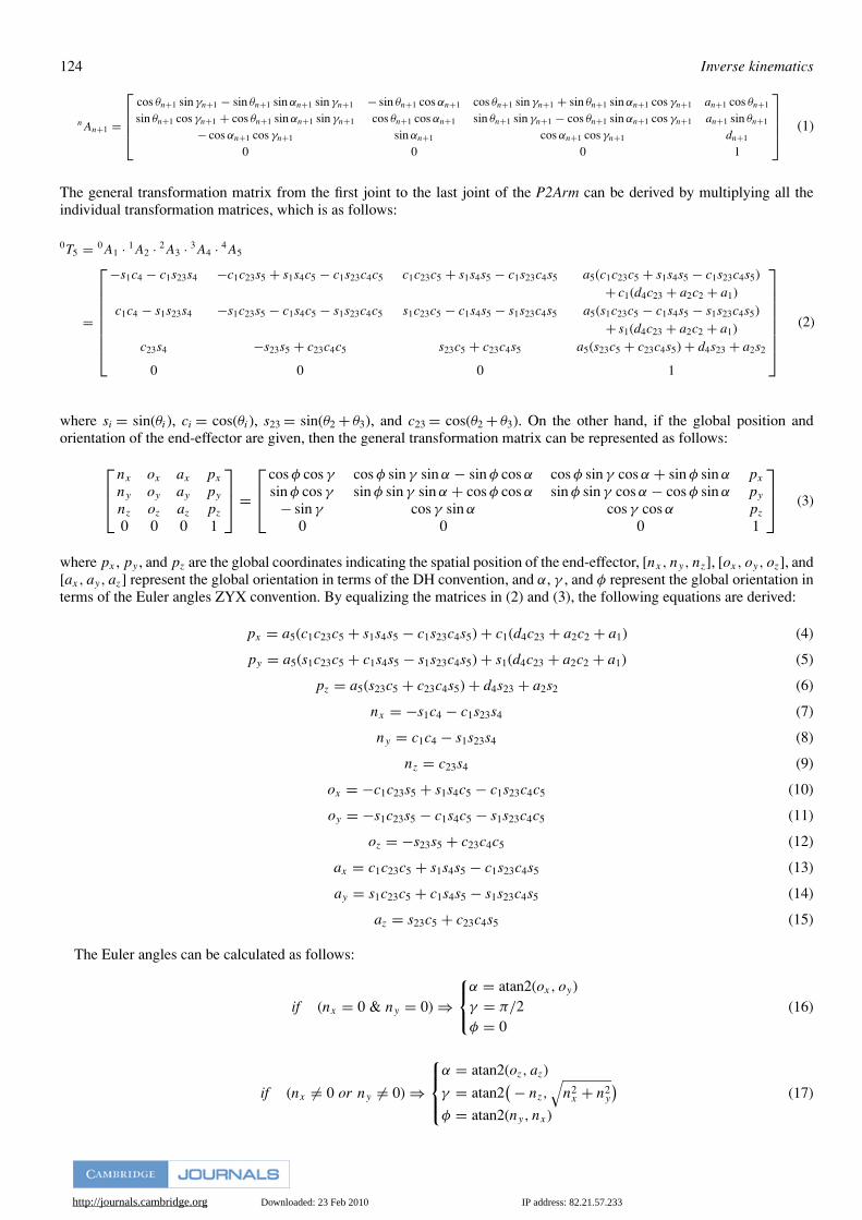
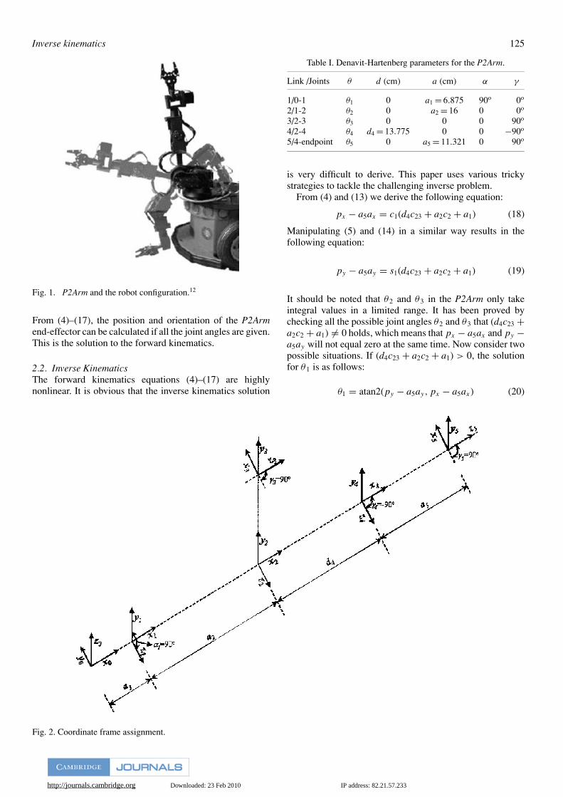
2.1. Forward kinematicsP2Arm is a 5-dof robotic arm with a gripper, as shown inFigure 1. All its joints are revolute. Driven by 6 servomotors,the arm can reach up to 50 cm from the centre of itsrotating base to the tip of its closed fingers. The Denavit-Hartenberg (DH) convention and methodology are usedin this section to derive its kinematics. The coordinateframe assignment and the DH parameters are depictedin Figure 2 and listed in Table I, respectively, where(x0, y0, z0) to (x4, y4, z4) represent the local coordinateframes at the five joints respectively, (x5, y5, z5) representsthe local coordinate frame at the end-effector, α, γ ,and θ are the rotation angles about x, y, and z axisrespectively. (x0, y0, z0) overlaps with the global coordinatesystem (X, Y, Z). More details about the definitions of thecoordinates and DH parameters can be found in our technicalreport11.
Based on the DH convention, the transformation matrixfrom joint n to joint n + 1 is given by:
http://journals.cambridge.org Downloaded: 23 Feb 2010 IP address: 82.21.57.233
124 Inverse kinematics
nAn+1 =
cos θn+1 sin γn+1 − sin θn+1 sin αn+1 sin γn+1 − sin θn+1 cos αn+1 cos θn+1 sin γn+1 + sin θn+1 sin αn+1 cos γn+1 an+1 cos θn+1
sin θn+1 cos γn+1 + cos θn+1 sin αn+1 sin γn+1 cos θn+1 cos αn+1 sin θn+1 sin γn+1 − cos θn+1 sin αn+1 cos γn+1 an+1 sin θn+1
− cos αn+1 cos γn+1 sin αn+1 cos αn+1 cos γn+1 dn+1
0 0 0 1
(1)
The general transformation matrix from the first joint to the last joint of the P2Arm can be derived by multiplying all theindividual transformation matrices, which is as follows:
0T5 = 0A1 · 1A2 · 2A3 · 3A4 · 4A5
=
−s1c4 − c1s23s4 −c1c23s5 + s1s4c5 − c1s23c4c5 c1c23c5 + s1s4s5 − c1s23c4s5 a5(c1c23c5 + s1s4s5 − c1s23c4s5)+ c1(d4c23 + a2c2 + a1)
c1c4 − s1s23s4 −s1c23s5 − c1s4c5 − s1s23c4c5 s1c23c5 − c1s4s5 − s1s23c4s5 a5(s1c23c5 − c1s4s5 − s1s23c4s5)+ s1(d4c23 + a2c2 + a1)
c23s4 −s23s5 + c23c4c5 s23c5 + c23c4s5 a5(s23c5 + c23c4s5) + d4s23 + a2s2
0 0 0 1
(2)
where si = sin(θi), ci = cos(θi), s23 = sin(θ2 + θ3), and c23 = cos(θ2 + θ3). On the other hand, if the global position andorientation of the end-effector are given, then the general transformation matrix can be represented as follows:
nx ox ax px
ny oy ay py
nz oz az pz
0 0 0 1
=
cos φ cos γ cos φ sin γ sin α − sin φ cos α cos φ sin γ cos α + sin φ sin α px
sin φ cos γ sin φ sin γ sin α + cos φ cos α sin φ sin γ cos α − cos φ sin α py
− sin γ cos γ sin α cos γ cos α pz
0 0 0 1
(3)
where px , py , and pz are the global coordinates indicating the spatial position of the end-effector, [nx, ny, nz], [ox, oy, oz], and[ax, ay, az] represent the global orientation in terms of the DH convention, and α, γ , and φ represent the global orientation interms of the Euler angles ZYX convention. By equalizing the matrices in (2) and (3), the following equations are derived:
px = a5(c1c23c5 + s1s4s5 − c1s23c4s5) + c1(d4c23 + a2c2 + a1) (4)
py = a5(s1c23c5 + c1s4s5 − s1s23c4s5) + s1(d4c23 + a2c2 + a1) (5)
pz = a5(s23c5 + c23c4s5) + d4s23 + a2s2 (6)
nx = −s1c4 − c1s23s4 (7)
ny = c1c4 − s1s23s4 (8)
nz = c23s4 (9)
ox = −c1c23s5 + s1s4c5 − c1s23c4c5 (10)
oy = −s1c23s5 − c1s4c5 − s1s23c4c5 (11)
oz = −s23s5 + c23c4c5 (12)
ax = c1c23c5 + s1s4s5 − c1s23c4s5 (13)
ay = s1c23c5 + c1s4s5 − s1s23c4s5 (14)
az = s23c5 + c23c4s5 (15)
The Euler angles can be calculated as follows:
if (nx = 0 & ny = 0) ⇒
α = atan2(ox, oy)γ = π/2φ = 0
(16)
if (nx �= 0 or ny �= 0) ⇒
α = atan2(oz, az)
γ = atan2( − nz,
√n2
x + n2y
)φ = atan2(ny, nx)
(17)
http://journals.cambridge.org Downloaded: 23 Feb 2010 IP address: 82.21.57.233
Inverse kinematics 125
Fig. 1. P2Arm and the robot configuration.12
From (4)–(17), the position and orientation of the P2Armend-effector can be calculated if all the joint angles are given.This is the solution to the forward kinematics.
2.2. Inverse KinematicsThe forward kinematics equations (4)–(17) are highlynonlinear. It is obvious that the inverse kinematics solution
Fig. 2. Coordinate frame assignment.
Table I. Denavit-Hartenberg parameters for the P2Arm.
Link /Joints θ d (cm) a (cm) α γ
1/0-1 θ1 0 a1 = 6.875 90o 0o
2/1-2 θ2 0 a2 = 16 0 0o
3/2-3 θ3 0 0 0 90o
4/2-4 θ4 d4 = 13.775 0 0 −90o
5/4-endpoint θ5 0 a5 = 11.321 0 90o
is very difficult to derive. This paper uses various trickystrategies to tackle the challenging inverse problem.
From (4) and (13) we derive the following equation:
px − a5ax = c1(d4c23 + a2c2 + a1) (18)
Manipulating (5) and (14) in a similar way results in thefollowing equation:
py − a5ay = s1(d4c23 + a2c2 + a1) (19)
It should be noted that θ2 and θ3 in the P2Arm only takeintegral values in a limited range. It has been proved bychecking all the possible joint angles θ2 and θ3 that (d4c23 +a2c2 + a1) �= 0 holds, which means that px − a5ax and py −a5ay will not equal zero at the same time. Now consider twopossible situations. If (d4c23 + a2c2 + a1) > 0, the solutionfor θ1 is as follows:
θ1 = atan2(py − a5ay, px − a5ax) (20)
http://journals.cambridge.org Downloaded: 23 Feb 2010 IP address: 82.21.57.233
126 Inverse kinematics
Otherwise, we have
θ1 = atan2(a5ay − py, a5ax − px) (21)
For deriving solutions for θ2 and θ3, (18) and (19) can berepresented as follows:
d4c23 + a2c2 = (px − a5ax)/c1 − a1 (22)d4c23 + a2c2 = (py − a5ay)/s1 − a1 (23)
From (6) and (15) we can derive the following equation:
d4s23 + a2s2 = pz − a5az (24)
It should be noted that (22) and (24) or (23) and (24) describethe forward kinematics of a 2-dof robotic arm, which hasanalytical inverse solutions. To avoid division by zero, letr = (px − a5ax)/c1 − a1 if s1 is very small or r = (py −a5ay)/s1 − a1 if c1 is very small, and let rz = pz − a5az.One set of possible solutions for θ2 and θ3 are as follows:
θ2 = atan2(rz, r) − acos
(r2 + r2
z + a22 − d2
4
2a2√
r2 + r2z
)+ 2m1π
(25)
θ3 = π − acos
(a2
2 + d24 − r2 − r2
z
2a2d4
)(26)
where m1 = −1, 0, or 1, making −π ≤ θ2 ≤ π . Another setof possible solutions for θ2 and θ3 are as follows:
θ2 = atan2(rz, r) + acos
(r2 + r2
z + a22 − d2
4
2a2√
r2 + r2z
)+ 2m1π
(27)
θ3 = −π + acos
(a2
2 + d24 − r2 − r2
z
2a2d4
)(28)
The derivation of the above solutions has been given inAppendix A. It should be noted that r �= 0, which meansthe above equations always provide certain solutions for θ2
and θ3.Now that θ1, θ2 and θ3 are known, the solutions for θ4 and
θ5 can be found by using the remaining forward kinematicsequations. It is important to avoid division by zero or the twovariables in atan2 function being zero at the same time.
Consider the case when c23 �= 0 first. From (9) we have
s4 = nz/c23 (29)
From (7) and (8) we obtain
c4 = −(nx + nzc1s23/c23)/s1 (30)
or if s1 is too small,
c4 = (ny + nzs1s23/c23)/c1 (31)
The solution for θ4 is
θ4 = atan2(nz/c23, −(nx + nzc1s23/c23)/s1) (32)
or if s1 is too small,
θ4 = atan2(nz/c23, (ny + nzs1s23/c23)/c1) (33)
Because nx , ny , and nz will not equal zero at the same time,which means s4 and c4 will not equal zero at the same time,thus the solution here for θ4 is certain. Knowing θ1, θ2, θ3
and θ4, it is easy to get a solution for θ5. If c4 �= 0 or s23 �= 0,from (12) and (15) we can derive the following equations:
s5 = azc23c4 − ozs23
c223c
24 + s2
23
(34)
c5 = ozc23c4 + azs23
c223c
24 + s2
23
(35)
θ5 = atan2(azc23c4 − ozs23, ozc23c4 + azs23) (36)
If c4 = 0 and s23 = 0, from (10) and (11) we obtain anothersolution for θ5, which is as follows:
s5 = −(oxc1 + oys1)/c23 (37)
c5 = (oxs1 − oyc1)/s4 (38)
θ5 = atan2(−(oxc1 + oys1)/c23, (oxs1 − oyc1)/s4) (39)
Now consider the solutions for θ4 and θ5 in the case whenc23 = 0. From (12) and (15) we obtain the solution for θ5 asfollows:
θ5 = atan2(−oz/s23, az/s23) (40)
From (7) and (8) we have
s4 = −(nxc1 − nys1)/s23 (41)
c4 = −nxs1 + nyc1 (42)
θ4 = atan2(−(nxc1 − nys1)/s23, −nxs1 + nyc1) (43)
It is difficult to prove that the two variables in the aboveatan2 functions for calculating θ4 and θ5 will not equal zeroat the same time. Some alternative solutions can be derivedto replace those that have the above problem. For instance,after θ5 is calculated, (41) can be replaced by:
s4 ={
(axs1 − ayc1)/s5 if c5 is too small
(oxs1 − oyc1)/c5 if s5 is too small(44)
The above derivation, with various conditions being takeninto account, provides a complete analytical solution to theinverse kinematics of the P2Arm. It should be noted thatwe do not know which solution for θ1 is true, (20) or (21),until we obtain all the joint angles and check if they providea correct solution using the forward kinematics. Similarly,there are two sets of possible solutions for θ2 and θ3, (25)–(26) or (27)–(28), and we do not know which set is trueuntil we check using the forward kinematics equations. Allthe other conditions used for solving θ4 and θ5 can bechecked at once when necessary. Therefore, four sets ofpossible solutions to the inverse kinematics of the P2Armhave been derived. Our strategy for choosing the correctsolution is to calculate all the four sets of possible solutions(joint angles), which generate four possible correspondingpositions and orientations using the forward kinematics. By
http://journals.cambridge.org Downloaded: 23 Feb 2010 IP address: 82.21.57.233
Inverse kinematics 127
comparing the errors between these four generated positionsand orientations and the given position and orientation, oneset of joint angles, which produces the minimum error, ischosen as the correct solution.
3. EXPERIMENTAL RESULTS AND DISCUSSIONSTheoretically, the equations for calculating joint angles θ1 toθ5 are correct. However, in practice there could be problemsin atan2 and acos calculation. For instance, the absolutevalue of the variable in acos could be slightly greater than 1due to computing inaccuracy, although it should not happenaccording to the derivation process in Appendix A. It willnot happen that the two variables in the atan2 functions forcalculating θ1 to θ3 equal zero at the same time. However,it is difficult to theoretically prove the same for equationsof calculating θ4 and θ5. In this section, experiments werecarried out to demonstrate the quality of the derived analyticalinverse kinematics model.
In the first batch of experiments, the testing positionand orientation data were generated using the forwardkinematics model with random joint angles that are withinphysically limited ranges so that they are guaranteed to bereachable. The experiments were conducted using both thesimulated arm model and the real P2Arm. We set the allowederror for position as eposition = 0.1 cm and for orientationas eorientation = 1◦. No error larger than the error thresholdwas produced at all with the program kept running on thesimulated arm for one week using over 500 million randomtesting positions and orientations. Because we do not haveequipment to measure directly and precisely the position andorientation of the end-effector of real P2Arm, what was done
was to read out the joint angle values from the P2Arm andthen calculate the position and orientation using the forwardkinematics model. This treatment will rule out mechanicalerror and control error, which is reasonable because themain purpose of the experiments in this paper is to examinewhether the inverse kinematics model is correct, rather thanto evaluate the whole robotic arm system. Again, no errorlarger than the error threshold was produced with the programrunning on the real P2Arm.
The second batch of experiments was similar to the firstbatch except that the testing positions and orientations weredisturbed with small random values. That is, the targetpositions and orientations could not be exactly reached (Theworking space of the P2Arm is discontinuous). This is fortesting the robustness of the derived inverse kinematicsmodel. In this batch of experiments, there were less than1% of the inverse solutions that did not satisfy the errorcriterion: eposition = 1 cm or eorientation = 3◦ (The orientation ismore difficult to satisfy than the position). This is still a verysatisfactory result, and in case an error exists (this happensless than once out of 100 trials), the optimal search methoddeveloped in reference [10] can always be used to find abetter solution.
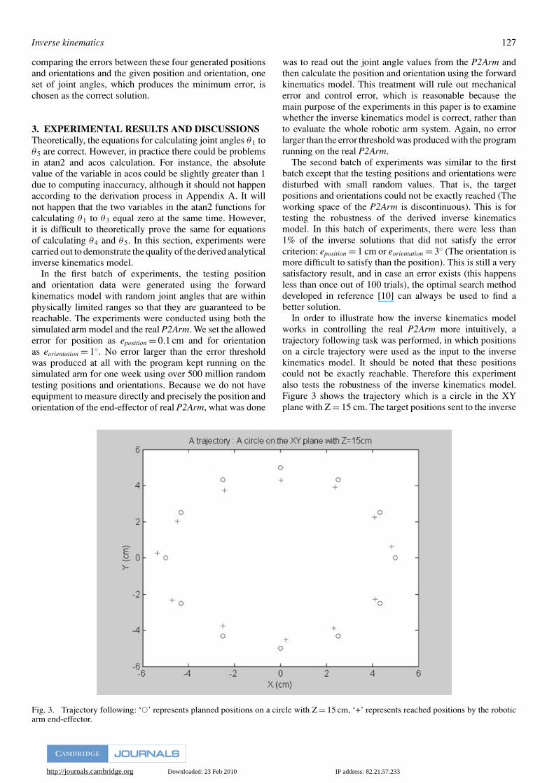
In order to illustrate how the inverse kinematics modelworks in controlling the real P2Arm more intuitively, atrajectory following task was performed, in which positionson a circle trajectory were used as the input to the inversekinematics model. It should be noted that these positionscould not be exactly reachable. Therefore this experimentalso tests the robustness of the inverse kinematics model.Figure 3 shows the trajectory which is a circle in the XYplane with Z = 15 cm. The target positions sent to the inverse
Fig. 3. Trajectory following: ‘�’ represents planned positions on a circle with Z = 15 cm, ‘+’ represents reached positions by the roboticarm end-effector.
http://journals.cambridge.org Downloaded: 23 Feb 2010 IP address: 82.21.57.233
128 Inverse kinematics
Table II. Coordinates of positions on the trajectory.
X Y Z X′ Y′ Z′
5.00 0.00 15.00 4.84 0.60 15.194.33 2.50 15.00 4.11 2.26 14.892.50 4.33 15.00 2.38 3.91 15.080.00 5.00 15.00 0.02 4.28 15.10
−2.50 4.33 15.00 −2.43 3.75 14.86−4.33 2.50 15.00 −4.50 2.02 14.97−5.00 0.00 15.00 −5.36 0.27 15.30−4.33 −2.50 15.00 −4.72 −2.33 14.98−2.50 −4.33 15.00 −2.50 −3.78 15.10
0.00 −5.00 15.00 0.24 −4.54 14.982.50 −4.33 15.00 2.33 −3.88 14.974.33 −2.50 15.00 4.12 −2.29 15.09
kinematics model are represented by ‘o’ and the reachedpositions using the inverse kinematics model control arerepresented by ‘+’. The coordinates of the target positions(X, Y, Z) and reached positions (X′, Y′, Z′) are given inTable II.
The above experimental results show that if the targetposition is exactly reachable the inverse kinematics modelis able to produce very accurate result, as shown in the firstbatch of experiments, and that if the target position is notexactly reachable the inverse kinematics model is able toprovide good approximate solutions.
4. CONCLUSIONSA complete analytical solution to the inverse kinematicsof a widely used robotic arm, P2Arm, is derived for thefirst time in this paper. The derived analytical inversekinematics model always provides correct joint angles formoving the arm end-effector to any given reachable positionsand orientations. If the given positions/orientations cannotbe exactly reached, the model is able to give very goodapproximate solutions for over 99% situations. We believethat the solution developed in this paper will make the P2Armmore useful in applications with unpredictable trajectorymovements in unknown environments. Without this solution,the trajectory movements of the P2Arm would have to bedone by manually making the arm follow the trajectory andrecording a sequence of joint angles for the later use in thetrajectory following task. The analytical solution is able toprovide joint angles automatically for a given trajectory. Themethods used for deriving the inverse kinematics model forthe P2Arm could be applied to other types of robotic arms,such as the EduBots developed by the Robotica Ltd13. Oursoftware for the P2Arm control based on the derived inversekinematics model will be made available to the public afterthis paper is published.
References1. R. D. Klafter, T. A. Chmielewski and M. Negin, Robotic
Engineering: An Integrated Approach (Prentice Hall, 1989).2. P. J. McKerrow, Introduction to Robotics (Addison-Wesley,
1991).3. S. B. Niku, Introduction to Robotics: Analysis, Systems,
Applications (Prentice Hall, 2001).
4. D. Demers and K. Kreutz-Delgado, “Learning global pro-perties of nonredundant kinematic mappings,” Int. J. ofRobotics Research 17, 547–560 (1998).
5. S. Tejomurtula and S. Kak, “Inverse kinematics in roboticsusing neural networks,” Information Sciences 116, 147–164(1999).
6. E. Oyama, A. Agah, K. F. MacDprman, T. Maeda and S. Tachi,“A modular neural network achitecture for inverse kinematicsmodel learning,” Neurocomputing 38–40, 797–805 (2001).
7. E. Oyama, N. Y. Chong, A. Agah, T. Maeda and S. Tachi,“Inverse kinematics learning by modular architecture neuralnetworks with performances prediction networks,” Proc. IEEEInt. Conf. on Robotics and Automation (2001) pp. 1006–1012.
8. Y. Li and S. H. Leong, “Kinematics control of redundantmanipulators using CMAC neural network,” Proc. 5th WorldMulticonference on Syst. Cybern. & Inform. (SCI2001), (2001)pp. 274–279.
9. B. Schafer, R. Krenn and B. Rebele, “On inverse kinematicsand kinetics of redundant space manipulator simulation,” J. ofComputational and Applied Mechanics, 4, 53–70 (2003).
10. E. M. Rosales, J. Q. Gan, H. Hu and E. Oyama, “A hybridapproach to inverse kinematics modeling and control ofPioneer 2 robotic arms,” Technical Report (University of Essex,October 2003).
11. E. M. Rosales and J. Q. Gan, “Forward and Inverse KinematicsModels for a 5-dof Pionner 2 Robotic Arm,” Technical Report(University of Essex, September 2003).
12. http://www.activrobots.com/ACCESSORIES/pioneerarm.html.13. http://www.robotica.co.uk/robotica/index.htm.
APPENDIX A. DERIVATION OF SOLUTIONS FOR θ2AND θ3Equations (22) and (24) or (23) and (24) can be representedas
d4c23 + a2c2 = r (A1)
d4s23 + a2s2 = rz (A2)
From (A1)–(A2), the following equation can be derived:
d24 + 2a2d4(c2c23 + s2s23) + a2
2 = r2 + r2z (A3)
From trigonometry we have
c2c23 + s2s23 = cos(θ3) = cos(−θ3)
= − cos(π − θ3) = − cos(θ3 − π) (A4)
Therefore there are several possible solutions for θ3, whichare as follows:
θ3 = ±acos
(r2 + r2
z − a22 − d2
4
2a2d4
)(A5)
or
θ3 = ±[π − acos
(a2
2 + d24 − r2 − r2
z
2a2d4
)](A6)
Now consider possible solutions for θ2. Expanding c23 ands23 in (A1) and (A2) generates the following equations:
(d4c3 + a2)c2 − (d4s3)s2 = r (A7)
(d4s3)c2 + (d4c3 + a2)s2 = rz (A8)
http://journals.cambridge.org Downloaded: 23 Feb 2010 IP address: 82.21.57.233
Inverse kinematics 129
Dividing both sides of (A7) and (A8) by√
r2 + r2z , we have
(d4c3 + a2)√r2 + r2
z
c2 − (d4s3)√r2 + r2
z
s2 = r√r2 + r2
z
(A9)
(d4s3)√r2 + r2
z
c2 + (d4c3 + a2)√r2 + r2
z
s2 = rz√r2 + r2
z
(A10)
Assuming sin(θ) = (d4s3)/√
r2 + r2z and cos(θ) =
(d4c3 + a2)/√
r2 + r2z , which is acceptable as this assump-
tion leads to sin2(θ) + cos2(θ) = 1, we transfer (A9) and(A10) into the following:
cos(θ + θ2) = r√r2 + r2
z
(A11)
sin(θ + θ2) = rz√r2 + r2
z
(A12)
Therefore,
θ + θ2 = atan2(rz, r) + 2m1π (A13)
θ = ±acos
(d4c3 + a2√
r2 + r2z
)
= ±acos
(r2 + r2
z + a22 − d2
4
2a2√
r2 + r2z
)(A14)
where m1 = −1, 0, or 1. It is clear that θ could be in [0, π]or (−π , 0). The range of θ will depend on the range of θ3. If0 ≤ θ3 ≤ π , then s3 > 0 and sin(θ) > 0, thus 0 ≤ θ ≤ π . If−π < θ3 < 0, then s3 < 0 and sin(θ) < 0, thus −π < θ < 0.Therefore, if
θ3 = π − acos
(a2
2 + d24 − r2 − r2
z
2a2d4
)(A15)
i.e., 0 ≤ θ3 ≤ π and 0 ≤ θ ≤ π , then
θ2 = atan2(rz, r) − acos
(r2 + r2
z + a22 − d2
4
2a2√
r2 + r2z
)+ 2m1π
(A16)
Otherwise, if
θ3 = −π + acos
(a2
2 + d24 − r2 − r2
z
2a2d4
)(A17)
i.e., −π < θ3 < 0 and −π < θ < 0, then
θ2 = atan2(rz, r) + acos
(r2 + r2
z + a22 − d2
4
2a2√
r2 + r2z
)+ 2m1π
(A18)
Related Documents


![Interfacing Toolbox for Robotic Arms with Real-Time ... · toolbox [2] includes functionalities for robotic manipulators, such as homogeneous transformations, direct and inverse kinematics,](https://static.cupdf.com/doc/110x72/5e3d49b52ab5f82c814b433a/interfacing-toolbox-for-robotic-arms-with-real-time-toolbox-2-includes-functionalities.jpg)