187 1 INTRODUCTION There are a number of different terminals located offshore, outside port limits or in sheltered anchorage areas where larger ships which cannaot approach ports or terminals ashore are berthed and the cargo transfer is carried out offshore [1], [3], [7], [9], [10]. In this paper we are going to describe the main characteristics of and comparisons between the typical Conventional Multi-Buoy Mooring (CBM/MBM), Single Point Mooring (SPM) and conventional Single Anchor Loading (SAL) systems (all designated for connection to amidships cargo manifold of a standard trading tanker) taking into account the hydro-meteorological boundary conditions (weather limitations) enabling ships to carry out safe cargo and manoeuvring operation offshore. The permanently moored vessels FSO/FPSO and DP shuttle tankers with Bow Loading Systems (BLS) are to be excluded from this scope. All items described in this paper are based on the common requirements covered by the specified oil field offshore operation manuals (e.g. [2], [6]), ship’s operator manuals, which include Teekay Shipping company experience factor [10] collected from the tanker fleet since 1979 and the author’s own experience (e.g. [3], [11]) in ship’s cargo and manoeuvring operations offshore collected at sea since 1997. 2 CONVENTIONAL MULTI-BUOY MOORING A Conventional Buoy Mooring (CBM) known also as Multiple Buoy Mooring (MBM) typically consists of the following main components (see Figure 1): mooring system with buoys, mooring legs and anchor points, pipeline end manifold (PLEM), pipeline to shore, subsea control system and hose string with pick-up arrangement [3], [7], [9]. The multiple buoys are fixed to the seabed by means of mooring lines and marine anchors in a rectangular pattern that allows safe mooring of a vessel which is positioned between the buoys with tug assistance. A Comparison Between Conventional Buoy Mooring CBM, Single Point Mooring SPM and Single Anchor Loading SAL Systems Considering the Hydro- meteorological Condition Limits for Safe Ship’s Operation Offshore G. Rutkowski Master Mariner Association, Gdynia, Poland Teekay Learning and Development Centre, Teekay Shipping Norway ABSTRACT: The purpose and scope of this paper is to describe the characteristics and make comparisons between: Conventional Buoy Mooring (CBM), also referred to as Multi-Buoy Moorings (MBM), Single Point Mooring (SPM) and conventional Single Anchor Loading (SAL) systems considering the hydro meteorological condition limits enabling safe ship’s cargo and manoeuvring operation offshore. These systems (CBM, SPM and SAL) are typically used for short term mooring applications offshore associated with the offloading and loading of bulk liquid fuel tankers transporting refined and unrefined products of crude oil. The permanently moored vessels FSO/FPSO are excluded from this scope. http://www.transnav.eu the International Journal on Marine Navigation and Safety of Sea Transportation Volume 13 Number 1 March 2019 DOI: 10.12716/1001.13.01.19

Welcome message from author
This document is posted to help you gain knowledge. Please leave a comment to let me know what you think about it! Share it to your friends and learn new things together.
Transcript
187
1 INTRODUCTION
There are a number of different terminals located offshore, outside port limits or in sheltered anchorage areas where larger ships which cannaot approach ports or terminals ashore are berthed and the cargo transfer is carried out offshore [1], [3], [7], [9], [10].
In this paper we are going to describe the main characteristics of and comparisons between the typical Conventional Multi-Buoy Mooring (CBM/MBM), Single Point Mooring (SPM) and conventional Single Anchor Loading (SAL) systems (all designated for connection to amidships cargo manifold of a standard trading tanker) taking into account the hydro-meteorological boundary conditions (weather limitations) enabling ships to carry out safe cargo and manoeuvring operation offshore. The permanently moored vessels FSO/FPSO and DP shuttle tankers with Bow Loading Systems (BLS) are to be excluded from this scope.
All items described in this paper are based on the common requirements covered by the specified oil
field offshore operation manuals (e.g. [2], [6]), ship’s operator manuals, which include Teekay Shipping company experience factor [10] collected from the tanker fleet since 1979 and the author’s own experience (e.g. [3], [11]) in ship’s cargo and manoeuvring operations offshore collected at sea since 1997.
2 CONVENTIONAL MULTI-BUOY MOORING
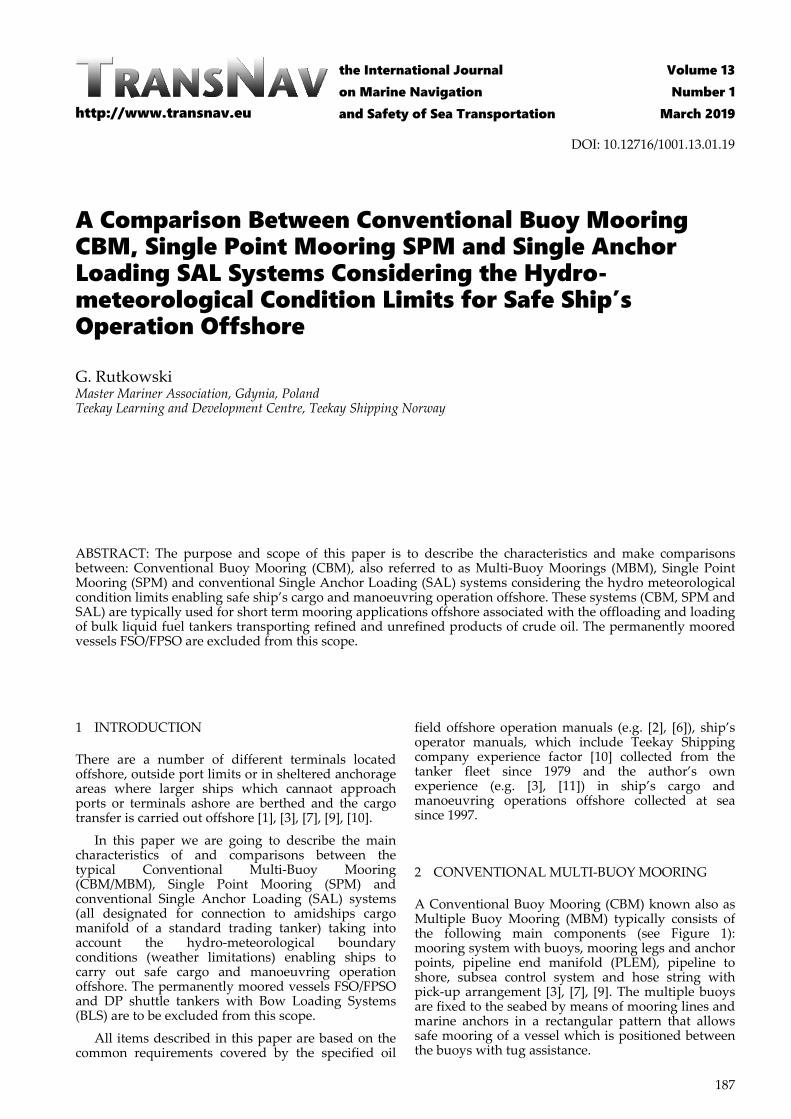
A Conventional Buoy Mooring (CBM) known also as Multiple Buoy Mooring (MBM) typically consists of the following main components (see Figure 1): mooring system with buoys, mooring legs and anchor points, pipeline end manifold (PLEM), pipeline to shore, subsea control system and hose string with pick-up arrangement [3], [7], [9]. The multiple buoys are fixed to the seabed by means of mooring lines and marine anchors in a rectangular pattern that allows safe mooring of a vessel which is positioned between the buoys with tug assistance.
A Comparison Between Conventional Buoy Mooring CBM, Single Point Mooring SPM and Single Anchor Loading SAL Systems Considering the Hydro-meteorological Condition Limits for Safe Ship’s Operation Offshore
G. Rutkowski Master Mariner Association, Gdynia, Poland Teekay Learning and Development Centre, Teekay Shipping Norway
ABSTRACT: The purpose and scope of this paper is to describe the characteristics and make comparisons between: Conventional Buoy Mooring (CBM), also referred to as Multi-Buoy Moorings (MBM), Single Point Mooring (SPM) and conventional Single Anchor Loading (SAL) systems considering the hydro meteorological condition limits enabling safe ship’s cargo and manoeuvring operation offshore. These systems (CBM, SPM and SAL) are typically used for short term mooring applications offshore associated with the offloading and loading of bulk liquid fuel tankers transporting refined and unrefined products of crude oil. The permanently moored vessels FSO/FPSO are excluded from this scope.
http://www.transnav.eu
the International Journal on Marine Navigation and Safety of Sea Transportation
Volume 13Number 1
March 2019
DOI: 10.12716/1001.13.01.19
188
Figure 1. Conventional Buoy Mooring CBM known also as Multiple Buoy Mooring MBM system. Source: Author’s own researches based on [7] and [11].
In this method the bow of the ship is secured by using both her anchors or forward mooring buoys and the stern is secured to buoy around it by using stern and quarter mooring system. It holds the vessel in a fixed position and does not allow it to weathervane. The buoys provide the strong points to which the vessel’s on-board mooring lines can be attached. As soon as the tanker has approached into position with the aid of tugs, a launch crew takes the tanker lines, one at a time, and tows them to the various mooring buoys.
The mooring system comprises of mooring buoys and mooring legs, where the buoys are generally moored to the seabed with chain legs and high capacity anchors, piles or clump weights depending on soil characteristics. The number of mooring lines and/or mooring chains is a function of the vessel size, hydro-meteorological conditions and navigational constraints.
When berthed, the tanker remains in a fixed position without tugs, and depending on the site-specific conditions & sometimes without vessel anchors. The ships’ mooring ropes are connected from either side of the vessel from the bow and the stern to quick release hooks on the conventional buoys. The buoys are manufactured either from steel or polymer materials. The buoys act as a mooring only structure. They contain no product transfer paths. The size of the buoys is a function of the counter buoyancy needed to hold the anchor chain for each buoy in position. Some mooring buoys are off-the-shelf products, while others have been specially designed to include features like quick disconnection couplings. The mooring system and layout of the buoys are always specifically designed to match the vessel’s requirements and local environmental conditions.
A typical CBM system of buoys have mooring assemblies through the centre of the units, terminating in a mooring eye on the bottom and pad eyes on top for the fitting of quick release hooks. The mooring legs for each buoy only consist of one anchor, unlike in the case of a CALM system where the buoy has between six and eight anchors. This is because the anchor chains of a CBM system only needs to work in one direction.
The product transfer system for CBMs consists of offloading hoses (connects the tanker to the subsea
PLEM), marine breakaway coupling (which acts as a weak link and prevents rupture of hoses/hawser and subsequent oil spills). The CBM system is especially valuable when no quay sites are available. It can also be combined with a fluid transfer system that enables connection of (subsea) pipelines to the amidships manifold of a conventional tanker. The end of the hose is provided with a pick-up line and a marker buoy. The hose string is picked up by a small support vessel that also assists the tanker with mooring to the buoys. After mooring the tanker to the buoys, pickup of the submerged hose strings and connecting the hoses to the amidships manifold, the loading or offloading operation may start. CBMs can be operated with up to four separate product lines. When no tanker is moored, the submersible hose or hoses are stored on the seabed away from the influence of the waves. For cryogenic fluids, the aerial hose is suspended from a tower to the amidships manifold of the liquefied gas carrier.
Typically, these systems are designed for nearshore applications with water depths starting from six metres up to approximately 30 m water depth, in beginning environmental conditions or conditions with a dominant directional character. The minimum depth is a constraint of the design vessel under keel clearance (UKC). As no weathervane mode is possible, it is often applied on projects where smaller tankers are employed. However, the system can be designed to berth all sizes of tankers, with the largest CBM system in the world designed to accommodate vessels up to 225 000 DWT (e.g. Puma multi-directional loading facility, Angola, 2015).
The tanker usually needs assistance in mooring and disconnecting from the mooring and navigating away from the CBM system. Ship usually can moor with winds up to 30 knots and head waves of 1.0 m. Vessel has to leave berth with winds of 60 knots and waves higher than 2.0 m to 3.0 m. Mooring typically takes 2 hrs (once vessel has arrived at CBM). Disconnecting from mooring typically takes 1.0 hrs. Hose connection and disconnection typically takes 1.0 hrs. Product unloading with winds up to 40 knots and waves higher than 2.0 m to 2.5 m. The offloading/loading operations can be undertaken via a number of hoses (one to four hoses) and can handle multiple products if required [5], [7].
189
3 SINGLE POINT MOORING
A Single Point Mooring (SPM), also known as Single Buoy Mooring or SBM is a loading buoy anchored offshore, that serves as a mooring point as well as an interconnection for tankers loading or offloading gas or liquid products. The basic principle of the buoy is to keep the position of the vessel with respect to the buoy steady and at the same time allowing vessels to swing to wind and sea [3], [9]. Often a tug is provided at the aft to keep the ship at a fixed angle and distance from the buoy. The buoy is fixed by positioning it in the centre of four to eight anchors connected to it. The ship is made fast to the buoy with the help of a single chain with hawser (or two) which is secured on board to the bow stopper. The vessel always takes the most favourable position in relation to the combination of wind, current and wave and is free to align itself with the prevailing environmental forces at the time. As the vessel in its stationary state is always positioned head-on into the winds/current’s direction, the total force is less than would be experienced by a vessel on a fixed mooring which is not always head-on into the prevailing conditions.
The vessel will approach the buoy with its bow into the dominant environment, thus maximising control while minimising the need for tug assistance. This solution is also good for DP dynamic positioning vessel. For conventional tankers a tug is usually required at all times during mooring and offloading to maintain the nominal amount of tension on the mooring hawsers to prevent collision of the tanker with the buoy and assist with the weathervane movements of the vessel.
The SPM system consists of four main components: the body of the buoy, mooring and anchoring elements, product transfer system and ancillary components [9]. The buoy body may be supported on static legs attached to the seabed, with a rotating part above water level connected to the offloading or loading tanker. These two sections are linked by a roller bearing, referred to as the ‘main bearing’. Alternatively, the buoy body may be held in place by multiple radiating anchor chains. The moored tanker can freely weathervane around the buoy and find a stable position due to this arrangement. The type of bearing used and the split between the rotating and geostatic parts determines the concept of the buoy. The size of the buoy is a function of the counter buoyancy needed to hold the anchor chains in position, and the chains are a function of the environmental conditions and the vessel size. Moorings fix the buoy to the sea bed. Buoy design must account for the behaviour of the buoy given applicable wind, wave and current conditions and tanker sizes. This determines the optimum mooring arrangement and size of the various mooring leg components. Anchoring points are greatly dependent on local soil condition and may consist of ships, rig, piles or gravity anchors, sinker or anchor chain joint to connect the buoy (SPM), anchor chain and chain stoppers to connect the chains to the buoy.
A tanker is moored to a buoy by means of a hawser arrangement setup according to Oil
Companies International Marine Forum (OCIMF) standards. The hawser arrangement usually consists of nylon rope, which is shackled to an integrated mooring joint on the buoy deck. At the tanker end of the hawser, a chafe chain is connected to prevent damage from the tanker fairlead. A load pin can be applied to the mooring joint on the buoy deck to measure hawser loads. Hawser systems use either one or two ropes depending on the largest size of vessel which would be moored to the buoy. The ropes would either be single-leg or grommet leg type ropes. These are usually connected to an OCIMF chafe chain on the export tanker side (either type A or B depending on the maximum size of the tanker and the mooring loads) [9]. This chafe chain would then be held in the chain stopper on board the export tanker. A basic hawser system would consist of the following (working from the buoy outwards): buoy-side shackle and bridle assembly for connection to the pad eye on the buoy, mooring hawser shackle, mooring hawser, chafe chain assembly, support buoy, pick-up messenger lines, marker buoy for retrieval from the water.
The heart of each buoy is the product transfer system. This system transfers products between the tanker and a pipeline end manifold (PLEM) located on the seabed. The basic product transfer system components are: flexible subsea hoses, generally referred to as ‘risers’, floating hose strings, marine breakaway coupling, product swivel, valves and piping. The risers are flexible hoses that connect the subsea piping to the buoy. The configuration varies on depth, sea state, buoy motions, tidal depth variation, lateral displacement due to mooring loads etc. In all cases the hose curvature changes to accommodate lateral and vertical movement of the buoy, and the hoses are supported at near neutral buoyancy by floats along the length. These are: Chinese lantern, in which two to four mirror symmetrical hoses connect the PLEM with the buoy, with the convexity of the curve facing radially outwards. Lazy-S, in which the riser hose leaves the PLEM at a steep angle, then flattens out before gradually curving upwards to meet the buoy almost vertically, in a flattened S-curve. Steep-S, in which the hose first rises roughly vertically to a submerged float, before making a sharp bend downwards followed by a slow curve through horizontal to a vertical attachment to the buoy.
Floating hose string, connects the buoy to the offloading tanker. The hose string can be equipped with a breakaway coupling to prevent rupture of hoses/hawser and subsequent oil spills. The product swivel is the connection between the geostatic and the rotating parts of the buoy. The swivel enables an offloading tanker to rotate with respect to the mooring buoy. Product swivels range in size depending on the size of attached piping and risers. Product swivels can provide one or several independent paths for fluids, gases, electrical signals or power. Swivels are equipped with a multiple seal arrangement to minimize the possibility of leakage of product into the environment [3], [8].
190
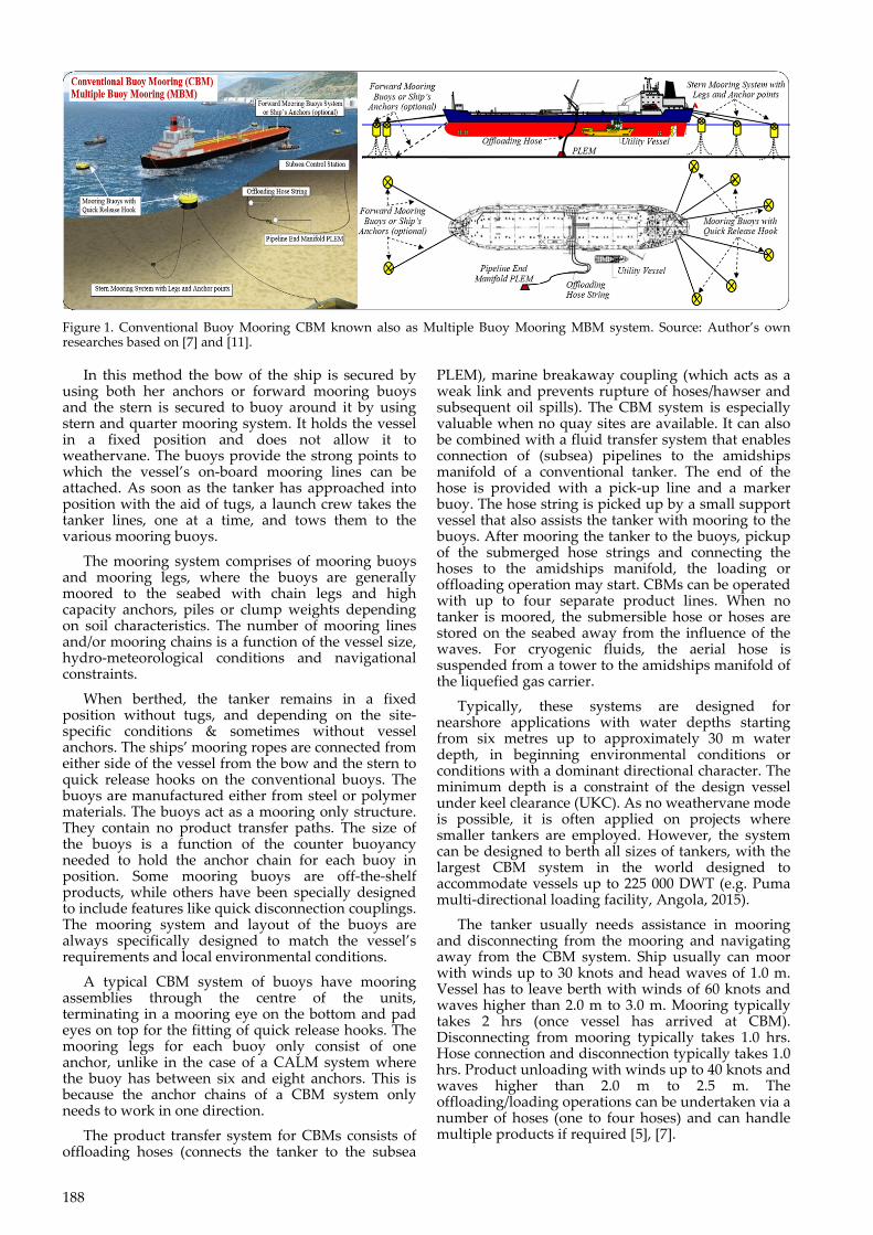
Figure 2. Catenary Anchor Leg Mooring (CALM) as example of Single Point Mooring (SPM)/Single Buoy Mooring (SBM) system with amidships cargo manifold side connection for operation offshore. Source: Author’s own researches based on [9] and [11].
Other possible components of SPMs are: a boat landing, providing access to the buoy deck, fenders to protect the buoy, lifting and handling equipment to aid materials handling, navigational aids for maritime visibility, and fog horn to keep moving vessel alert, electrical subsystem power navigation aids or other equipment (provided either by batteries which are recharged on a regular basis or solar power systems to maintain the charge in the battery packs) and optionally the hydraulic system to allow the remote operation of the PLEM valves if required [9].
SPMs are the link between geostatic subsea manifold connections and weather-vanning tankers. They are capable of handling any size ship, even very large crude carriers (VLCC) where no alternative facility is available. In shallow water SPMs are used to load and unload crude oil and refined products from inshore and offshore oilfields or refineries, usually through some form of storage system. These buoys are usually suitable for use by all types of oil tanker. In deep water oil fields, SPMs are usually used to load crude oil direct from the production platforms, where there are economic reasons not to run a pipeline to the shore. These moorings usually supply to dedicated tankers (DP class shuttle tankers) which can moor without assistance.
Nowadays there are several types of Single Point Mooring (SPM) systems in use. Most of the SPM buoys are typically used for short term mooring applications offshore. This system is preferential when deep waters are not available close to shore. The minimum depth is a constraint for the design vessel Under Keel Clearance (UKC). A commonly used configuration for SPM is the Catenary Anchor Leg Mooring (CALM) and Single Anchor Leg Mooring (SALM).
CALMs are usually located in water depths between 20 to 100 meters and connected to a shore storage facility (tank farm) or to offshore production platforms by means of a submarine pipeline. Since early 2000, the CALM design has been also used and adapted to deep-water conditions, greater than 1,000 meters [3], [9], [11]. For this application, the CALM is used as an offloading system for a deep-water Floating Production Storage and Offloading unit (FPSO) which are not covered by the scope of this paper.
CALM holds the buoy in place by an anchor chain that extend in catenaries to anchor points some distance from the buoy. The SALM system is similar, except that the SALM is anchored by a single anchor leg [5], [7], [9]. The SALM system prevents collision damage to the swivels by placing them underwater and below the keel level of the tanker. Any damage should then only affect the simple surface buoy and be relatively cheap to repair. The underwater swivels do however have maintenance disadvantages. To prevent the flexible loading pipe clashing with the mooring chains the catenary is replaced by a single, nominally vertical, tensioned chain mooring leg. In shallow water the fluid swivels are on the base. In deep water the fluid swivels could be attached part way up the mooring leg. This would ease maintenance of the swivels and the flexible pipes from the swivels to the tanker. In such case the primary benefit of a CALM Buoy over a SALM Buoy is ease of maintenance. The mechanical U-Joints of a SALM are removed, and the fluid swivel is located above the water surface.
A SALM can be employed as an unmanned tanker loading or discharge terminal with multiple fluid transfer circuits. The configuration of a SALM is highly elastic over a very wide range of water depths. This inherent elasticity enables cargo transfer operations to continue under adverse weather and sea-state conditions.
The vast majority of Marine Terminals installed since the mid-1990s have been CALM Buoys because of these design improvements. This configuration uses six or eight heavy anchor chains placed radially around the buoy, of a size to suit the designed load and attached to an anchor or pile to provide the required holding power. The anchor chains are pre-tensioned to ensure that the buoy is held in position above the PLEM. As the load from the tanker is applied, the heavy chains on the far side straighten and lift off the seabed to apply the balancing load. Under full design load there is still some shackles of chain lying on the bottom. Figure 2 illustrates a Turntable type SPM CALM system during installation.
Less commonly used SPM configurations include Vertical Anchor Leg Mooring (VALM), which is seldom used (e.g. offshore Brazil), two types of single point mooring tower (Jacket type, which has a jacket
191
piled to the seabed with a turntable on top which carries the mooring gear and pipework or Spring pile type, which has steel pipe risers in the structure), Exposed Location Single Buoy Mooring (ELSBM) which stores the mooring line and cargo hose on drums when not in use (configuration suitable for use in rough sea conditions), Articulated Loading Platform (ALP) which is also suited for rough sea conditions.
There are no vessel constraints for an SPM system. The SPM CALM buoy configuration can accommodate the largest vessels, including VLCCs. In general, while approaching single point or single buoy moorings weather is a major criterion in determining whether to berth the vessel or not. Calm seas with low swell and wind force below 15 knots are considered favourable to make an approach. Presence of strong tidal current limits the interval for berthing and un-berthing. The headway approach has to be slow often less than while at the same time approaching at a smaller angle to the buoy and then gradually hauling in the buoy messenger rope and pulling the vessel slowly towards the buoy using engine kicks at short intervals to control and maintain headway along with mooring winches to haul in the vessel when she nears about 150-200 meters from the buoy. For un-berthing the chain is released from the bow stopper and a short kick on the engines going astern swings the bow to starboard for right handed propellers thus clearing the vessel of the buoy. Tug’s assistance can also be used to pull the vessel astern and clear it of the buoy.
Ships usually can moor with winds up to 30 knots and head waves of 2.0 m to 2.5 m. Vessel has to leave berth when winds exceed 60 knots and waves are higher than 3.5 m to 5.0 m. Approach to the SPM can be from any direction (from a mooring perspective). Mooring typically takes 15 min (once vessel has arrived at SPM buoy). Disconnecting from mooring does not necessarily need tug assistance, although tugs may be required depending on the local site condition and availability of space for vessel manoeuvring. Disconnecting from mooring typically takes 15 min.
Hose connection and/or disconnection on amidships manifold typically takes 1 hour. Product unloading possible with winds up to 40 knots and head waves of 3.0 m to 4.5 m. SPM system can be also designated for DP dynamic positioning vessels with BLS (Bow Loading System), where offloading hose can be connected directly to BLS system within about 10 to 15 minutes.
For conventional tankers the fulltime tug assistance can be required to assist with weather-vanning and prevent collision between the vessel and the SPM. Typically, vessels are only able to offload a single product at a time, however SPMs with amidships manifold connection can be designed to handle multiple products if required.
4 SINGLE ANCHOR LOADING
Single Anchor Loading (SAL) is offshore loading system introduced in the late 1990’s, that serves as a
single mooring point via hawser to the underwater strong base anchor as well as an interconnection for tankers loading or offloading gas or liquid products [1], [2]. SAL was developed as low-cost alternative to the Submerged Turret Loading (STL) system for use in the situation where traditional CALM buoys cannot be used. As the SAL is subsea the risk of collision between the tanker and traditional CALM or SPM buoy is eliminated. On SAL system the vessel always takes the most favourable position in relation to the combination of wind, current and wave and is free to align itself with the prevailing environmental forces at the time.
The central elements of the SAL system are a mooring and a fluid swivel with a single mooring line (hawser) and a flexible riser for fluid transfer attached, anchored at the sea bed by the use of a single anchor. The anchor also functions as the pipeline end manifold (PLEM) for the seabed export flow line. A tanker is hooked up to the system by pulling the mooring line and the riser together from the seabed and up to the bow of the vessel. Here the mooring line is secured and the riser is connected to the vessel. Moored to the SAL system, a tanker can freely weathervane. Disconnection is performed by lowering the mooring line and the riser down to the seabed.
Nowadays there are a several types of SAL systems in use. The SAL flexible riser (offloading hose) can either be designated for connection to a standard shuttle tanker bow loading system BLS or to the typical amidships manifold of a standard trading tanker.
The SAL can be equipped with clump weight system (e.g. Hanze SAL installed in 2001, Solan SAL installed in 2015) or underwater buoyancy systems (e.g. Banff SAL or South Arne SAL installed in 1998). Typical SAL system is usually equipped with strong mooring hawser with chafing chain designated for tanker with chain stopper located forward for single point mooring SPM system on board the tanker vessel (e.g. installation of South Arne SAL with mooring hawser capability limited to 450 tons on weak link). However, there are also SAL installation without upper mooring system, which are in configuration typical for traditional offshore loading system OLS, which are designated only for full DP shuttle tankers equipped with bow loading system.
Nowadays most of the SAL systems are typically used offshore for short term mooring applications recommended for DP shuttle tankers equipped with BLS. However, there is also the possibility to use the SAL systems for conventional tankers with amidships cargo manifold side offloading as presented on Figure 3. In general approach the typical SAL terminal is quite easy to install. It has been noted that new SAL terminal can be installed on oil field offshore just within few weeks’ period. It has been also noted that the old SAL systems can be easy reused and/or upgraded (e.g. Ardmore twin SAL systems have been re-used for Kittywake SAL installation in 2005 and Don SAL installation in 2008, Siri SAL buoyancy system has been upgraded from buoyancy SAL system to clump weight SAL system in 2009).
192
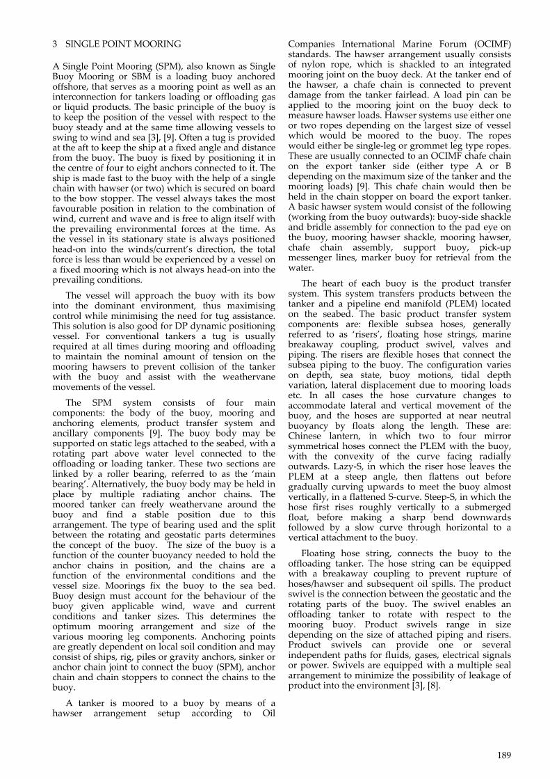
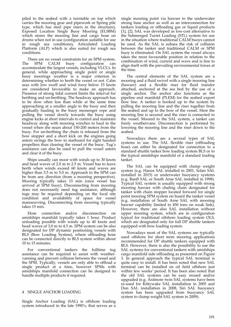
Figure 3. Configuration of Single Anchor Loading (SAL) system for standard trading tankers with hose connected to amidships cargo manifold. Source: Author’s own researches based on [2] and [11].
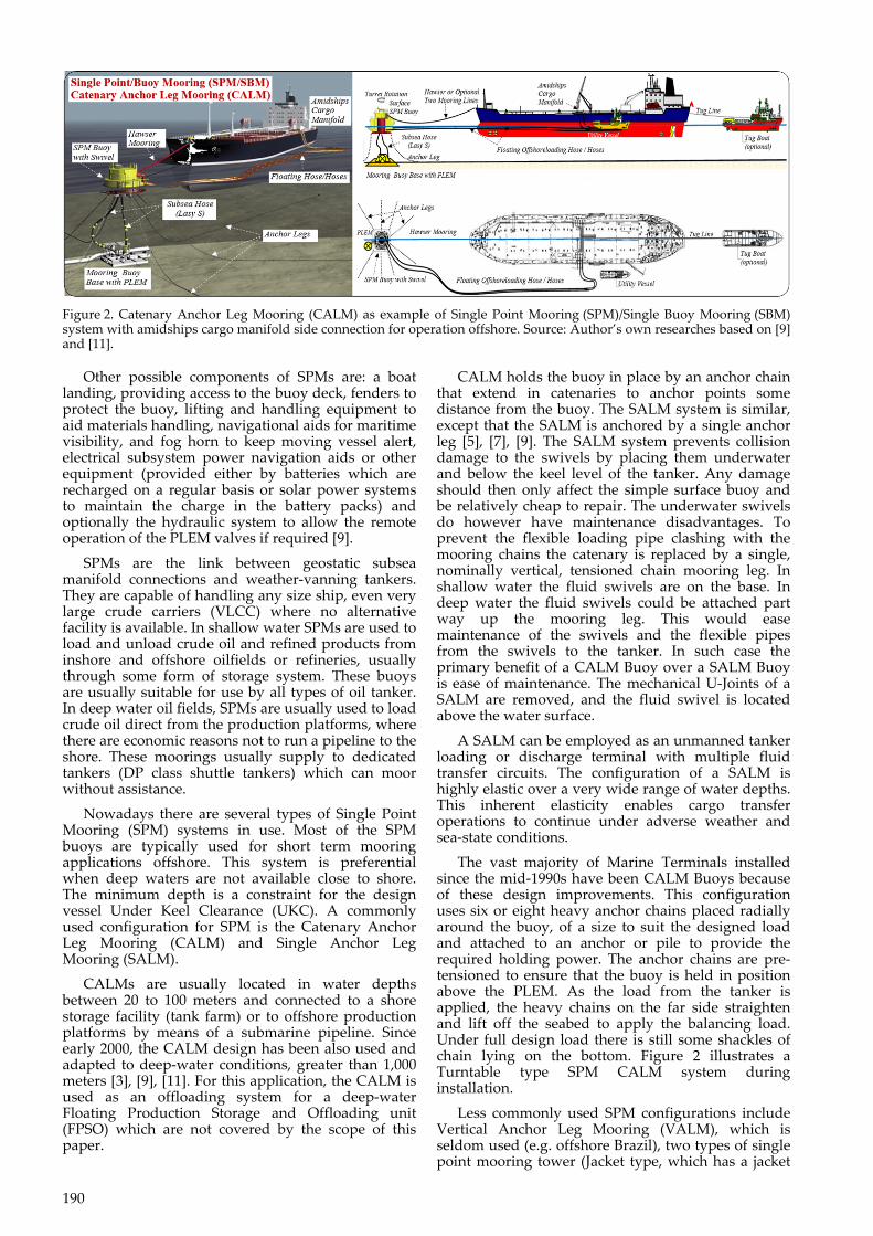
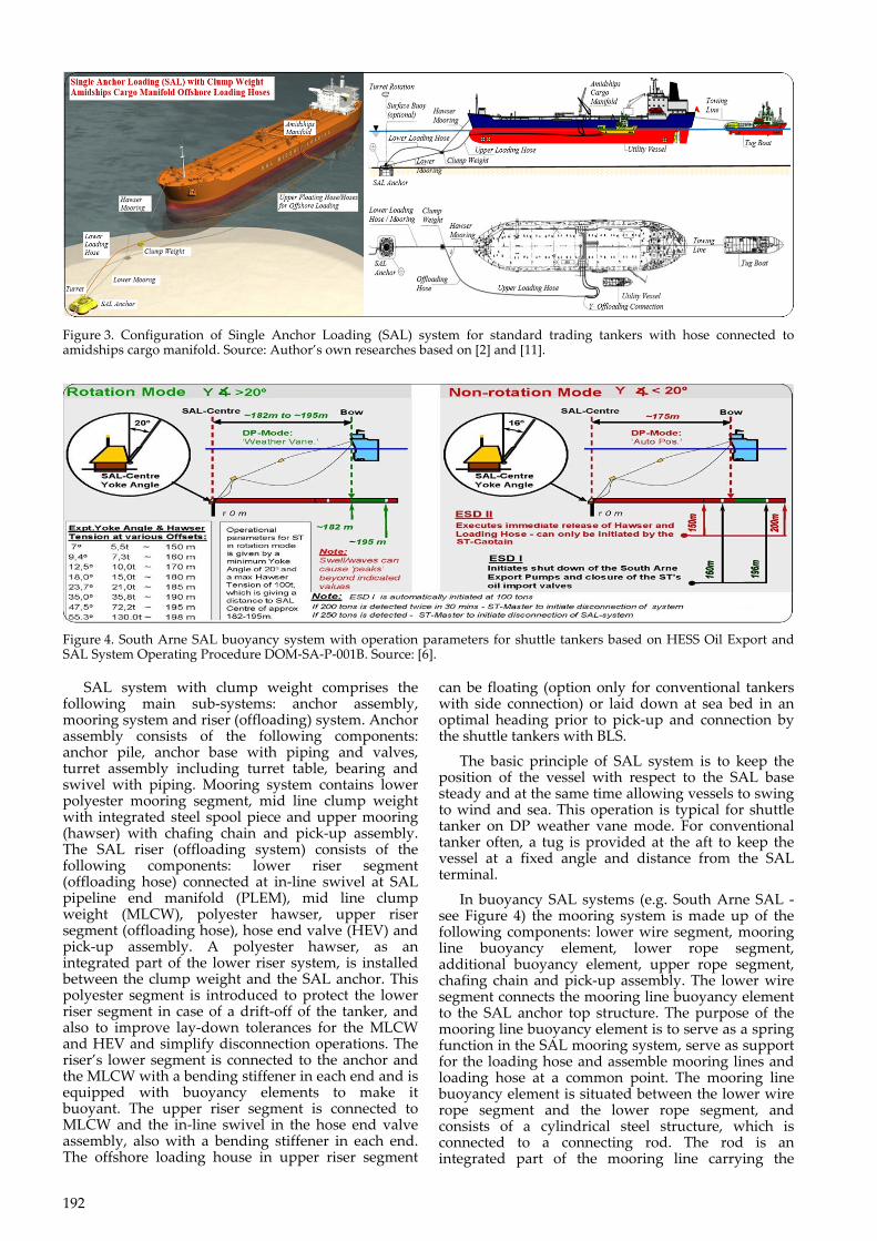
Figure 4. South Arne SAL buoyancy system with operation parameters for shuttle tankers based on HESS Oil Export and SAL System Operating Procedure DOM-SA-P-001B. Source: [6].
SAL system with clump weight comprises the following main sub-systems: anchor assembly, mooring system and riser (offloading) system. Anchor assembly consists of the following components: anchor pile, anchor base with piping and valves, turret assembly including turret table, bearing and swivel with piping. Mooring system contains lower polyester mooring segment, mid line clump weight with integrated steel spool piece and upper mooring (hawser) with chafing chain and pick-up assembly. The SAL riser (offloading system) consists of the following components: lower riser segment (offloading hose) connected at in-line swivel at SAL pipeline end manifold (PLEM), mid line clump weight (MLCW), polyester hawser, upper riser segment (offloading hose), hose end valve (HEV) and pick-up assembly. A polyester hawser, as an integrated part of the lower riser system, is installed between the clump weight and the SAL anchor. This polyester segment is introduced to protect the lower riser segment in case of a drift-off of the tanker, and also to improve lay-down tolerances for the MLCW and HEV and simplify disconnection operations. The riser’s lower segment is connected to the anchor and the MLCW with a bending stiffener in each end and is equipped with buoyancy elements to make it buoyant. The upper riser segment is connected to MLCW and the in-line swivel in the hose end valve assembly, also with a bending stiffener in each end. The offshore loading house in upper riser segment
can be floating (option only for conventional tankers with side connection) or laid down at sea bed in an optimal heading prior to pick-up and connection by the shuttle tankers with BLS.
The basic principle of SAL system is to keep the position of the vessel with respect to the SAL base steady and at the same time allowing vessels to swing to wind and sea. This operation is typical for shuttle tanker on DP weather vane mode. For conventional tanker often, a tug is provided at the aft to keep the vessel at a fixed angle and distance from the SAL terminal.
In buoyancy SAL systems (e.g. South Arne SAL - see Figure 4) the mooring system is made up of the following components: lower wire segment, mooring line buoyancy element, lower rope segment, additional buoyancy element, upper rope segment, chafing chain and pick-up assembly. The lower wire segment connects the mooring line buoyancy element to the SAL anchor top structure. The purpose of the mooring line buoyancy element is to serve as a spring function in the SAL mooring system, serve as support for the loading hose and assemble mooring lines and loading hose at a common point. The mooring line buoyancy element is situated between the lower wire rope segment and the lower rope segment, and consists of a cylindrical steel structure, which is connected to a connecting rod. The rod is an integrated part of the mooring line carrying the
193
mooring line tension that is no mooring forces are transferred through the hull of the buoyancy element. In light of SAL mooring system handling requirements during operation, fibre ropes were chosen instead of wire ropes. Two fibre rope segments, a lower fibre rope segment and an upper fibre rope segment connect the mooring line buoyancy element and the chafing chain, via the additional buoyancy element. Both sections of rope are manufactured from Polyester. The additional buoyancy element is designed to avoid contact between the fibre rope segments and the seabed, and to reduce the stiffness of the mooring system in disconnected condition. However, this SAL system is designated only for DP shuttle tanker with BLS system.
The SAL installation is fixed by SAL anchor. The ship is made fast to the SAL with the help of a single chain with hawser which is secured on board to the bow stopper. The vessel always takes the most favourable position in relation to the combination of wind, current and wave and is free to align itself with the prevailing environmental forces at the time. As the vessel in its stationary state is always positioned head-on into the winds/currents direction, the total force is less than would be experienced by a vessel on a fixed mooring which is not always head-on into the prevailing conditions. The vessel will approach the SAL with its bow into the dominant environment, thus maximising control while minimising the need for tug assistance. This solution is good for DP dynamic positioning vessel. For conventional tankers a tug is usually required at all times during mooring and offloading operation to maintain the nominal amount of tension on the mooring hawsers and assist with the weathervane movements of the vessel.
The SAL Anchor Assembly consists of the following main components: anchor pile, anchor base structure, turret assembly, including turret adapter, turret table, bearings and bearing locking arrangement, crude swivel, piping from crude swivel to flexible riser, riser connector and support, piping from sub-sea pipeline to crude swivel, acoustic control system (optional), crude oil valve for branch piping (to crude swivel) and crude oil valve for main piping. The anchor base is fabricated on top of a conical structure that fits to the pre-installed anchor pile. During the final installation campaign, the conical structure is grouted to the anchor pile to achieve the required permanent structural capacity. The Anchor Base structure transfers the forces from the riser system, via the bearing arrangement in the turret into the anchor pile. The center of the anchor base consists of the removable turret assembly. The connection to the removable module consists of a robust vertical pipe with a flange connection and guiding for the turret adapter module. The interface between the anchor base structure and the anchor pile is a grouted connection. The soil inside the top of the anchor pile is dredged out after installation and a mating insert below the SAL base structure penetrates into the anchor pile. The void space between the anchor pile and the mating insert on the anchor base is filled with grouting to form a rigid structural connection.
The turret assembly is the main component that consists of the turret adapter, turret table bearings
and bearing locking arrangement, crude swivel, riser connector and support and lower polyester segment connection point. The turret assembly is connected to the anchor base structure by a bolted flange. The turret assembly is designed to perform without any maintenance throughout the design life of the system (30 years). However, if found required, the turret assembly can be unbolted and retrieved to surface for maintenance or repair, or it can be replaced with an interchangeable new turret assembly. The arrangement that transfers the global loads from the riser system consists of a turret shaft, turret table and a bearing arrangement. It is designed with basis in the same turret components as the field proven STL/STP systems. The system is normally designed to transfer mooring loads from a passive vessel. The upper bearing ring supporting the upper axial bearing is locked to the central turret shaft by means of a segment locking system fitted into a circular groove of the centre shaft. The bearings are fixed to the turret table. The turret table is equipped with a support structure for the riser. The support structure ensures that all global loads from the riser (tension, shear and moment) are transferred into the turret table, which provides the moment arm for turning the turret table and the crude oil swivel.
The crude swivel is located on top of the anchor. The top of the swivel is rigidly connected to a frame on the top of the turret table to prevent loads from the riser to be transferred into the crude swivel. The rotation of the swivel will be driven by the rotating motion of the turret table via the piping clamped to the anchor base. The rotating motion originates mainly from the tension loads in the riser. The inline fluid swivel is a robust and compact unit with few sensitive parts. It is capable of handling all relevant external forces from the attaching piping with a good margin. It is not sensitive to moisture and water ingress, as it holds no roller bearing elements. The fluid swivel comprises a set of double axials thrust bearings and double radial bearings to take up external loads while allowing rotation. All bearings are self- lubricating, i.e. bronze with solid lubricant depots. The process seals are arranged as rod seal type (axial seals). There are double process seals, with leak collection in-between. Additionally, to prevent water and dust ingress into the bearing cavity there is a scraper and a seal on the outside of the bearing cavity.
SAL systems are usually located in water depths between 30 to 100 meters and are connected to a shore storage facility (tank farm) or to offshore production platforms by means of a submarine pipeline. Nowadays most of the SAL systems are designated for DP shuttle tankers with BLS system. SAL configuration can accommodate the largest vessels, including VLCCs.
Shuttle tankers can moor to SAL system with significant sea waves up to 4.5 m (maximum wave heights 8.5 m) and stay connected to SAL when loading with significant sea waves up to 5.5 m (maximum wave heights 9.5 m) and disconnection in seas as high as 7.0 m [1], [2]. Conventional tankers usually can moor with winds up to 30 knots and head waves of 2,0 m to 2.5 m. Vessel has to leave berth when winds exceed 60 knots and waves are higher than 3.5 m to 5.0 m. The above values are normative
194
and must be considered in connection with current weather conditions and whether conditions are improving, stabilizing or worsening. Approach, loading and discontinuation of these activities are always subject to the Master’s final approval.
The operational limits for single anchor loading (SAL) loading are the same as for SPM loading. In addition, there is a limited sector (±5°) for positioning when picking up the line from the bottom. On DP shuttle tankers two different loading modes, rotation and non-rotation modes may be used for loading on SAL systems (see figure 4). Non-rotation mode (Auto Position) is normally used when weather conditions allow it, to reduce strain on the loading system. Rotation mode (Weather Vane) is normally used when weather conditions are above winds of Beaufort force 4 and/or sea state 2 or above. Hawser tension limits for SAL are normally higher than other systems for offshore loading with shut down (green line failure) on 200 t. Restricted zones are defined where other installations are placed nearby and when there is a risk that the vessel, in an emergency, may drift towards other offshore installations.
Approach to the SAL can be from any direction (from a mooring perspective). If needed the SAL system can be rotated and laid down in an optimal heading by supporting tug prior to pick-up and connection by approaching tanker. Mooring typically takes 30 min to 1 hour (once vessel has arrived at SAL installation and connect mooring pick up assembly). Disconnecting from mooring does not necessarily need tug assistance, although tugs may be required depending on the local site condition and availability of space for vessel manoeuvring. For conventional tankers the fulltime tug assistance can be required to assist with mooring, unmooring and weather-
vanning. Disconnecting from mooring typically takes about 30 min. Hose connection and/or disconnection on amidships manifold typically takes 1 hour. Product unloading possible with winds up to 40 knots and head waves of 3.0 m to 4.5 m. Connection to BLS usually takes about 15 minutes. Typically, vessels are only able to offload a single product at a time, however SPMs with amidships manifold connection can be designed to handle multiple products if required.
5 COMPARISON SUMMARY
Summing up the above, it can be assumed that in the offshore sector, the expensive offshore loading systems will be replaced by the cheaper and equally effective solutions. The author also believes that the traditional single anchor loading (SAL) systems with the Hawser mooring system will be replaced by the modified SAL systems in the OLS configuration (without the Hawser system attached), which is designated only for DP shuttle tankers.
Conventional buoy mooring system CBM and single point mooring system SPM will continue to be found in common use by conventional tankers and/or storage units FSO on shallow waters (CBM up to 30 m depth and SPM up to 100 m depth).
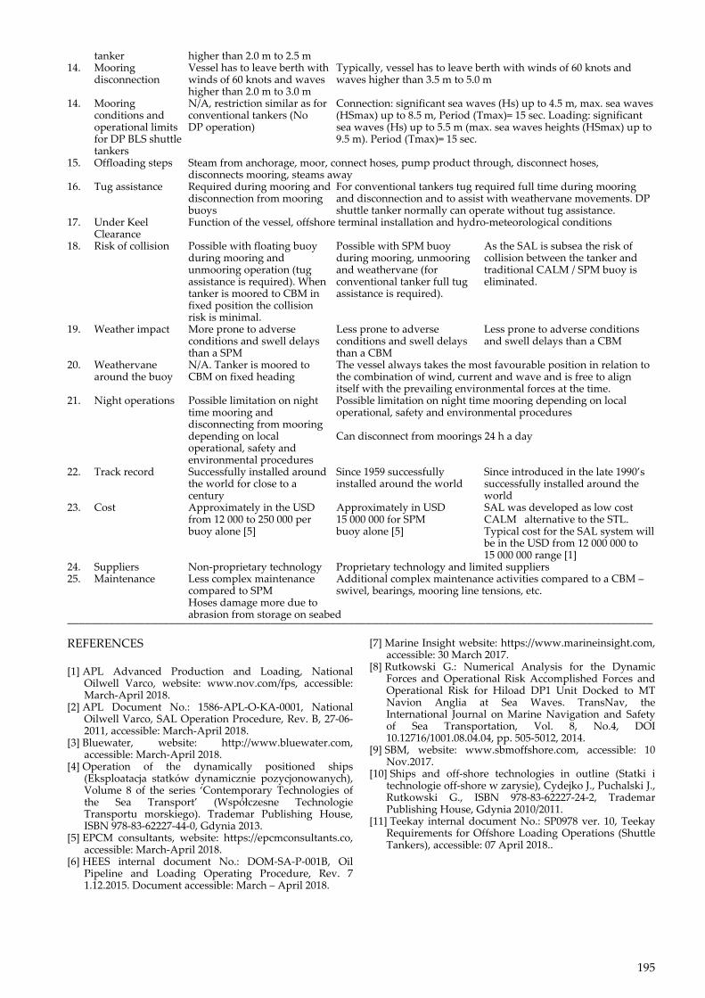
A summary comparison between conventional buoy mooring system CBM, single point mooring system SPM and single anchor loading system SAL considering operational limits and the hydro-meteorological condition limits for safe ship’s operation offshore has been presented in the following table:
Table 1. Comparisons between conventional buoy mooring system CBM, single point mooring system SPM and single anchor loading system SAL considering operational limits and the hydro-meteorological condition limits for safe ship’s operation offshore. Source: Author’s own researches. __________________________________________________________________________________________________ No Criteria CBM SPM SAL __________________________________________________________________________________________________ 1. Vessel size Vessel sizes typically up to Vessel sizes unlimited Vessel sizes unlimited 80 000 dwt, but up to 225 000 dwt has been installed 2. Operating water Usually up to 30 m water Up to 100 m water depth Up to 100 m water depth depth depth 3. Mooring method Multi-buoy mooring system Single buoy mooring system Single point mooring system with optional with ship’s anchor with one or two hawsers one hawser 4. Approach Can only approach from Can approach from any position – and therefore can choose to limited positions approach into prevailing weather conditions 5. Mooring time Typically, about 2.0 h Typically, about 15 min Typically, about 30 min (after arriving at mooring position) 6. Hose connection Typically, about 1.0 h Typically, about 1.0 h Typically, about 1.0 h time amidships 7. BLS connection N/A Typically, about 15 min Typically, about 15 min 8. Time for hose Typically, about 1.0 h Typically, about 1.0 h Typically, about 1.0 h disconnection 9. Offloading time Function of vessel pumps capacity, line size and distance 10. Time for mooring Typically: 1.0 h Typically: 15 min. Typically: 20 min to 30 min. disconnection 11. Net total time Typically: 2.5 h longer Typically: 2.5 h quicker Typically: 2 h quicker compared to difference compared to SPM compared to CBM CBM 12. Mooring conditions Able to moor with winds up Able to moor with winds up to 30 knots and head waves of 2.0 m for conventional to 30 knots and head waves to 2.5 m tanker of 1.0 m 13. Operating limit for Product unloading with wind Product offloading possible with wind up to 40 knots and head conventional up to 40 knots and waves waves of 3.0 m to 4.5 m
195
tanker higher than 2.0 m to 2.5 m 14. Mooring Vessel has to leave berth with Typically, vessel has to leave berth with winds of 60 knots and disconnection winds of 60 knots and waves waves higher than 3.5 m to 5.0 m higher than 2.0 m to 3.0 m 14. Mooring N/A, restriction similar as for Connection: significant sea waves (Hs) up to 4.5 m, max. sea waves conditions and conventional tankers (No (HSmax) up to 8.5 m, Period (Tmax)= 15 sec. Loading: significant operational limits DP operation) sea waves (Hs) up to 5.5 m (max. sea waves heights (HSmax) up to for DP BLS shuttle 9.5 m). Period (Tmax)= 15 sec. tankers 15. Offloading steps Steam from anchorage, moor, connect hoses, pump product through, disconnect hoses, disconnects mooring, steams away 16. Tug assistance Required during mooring and For conventional tankers tug required full time during mooring disconnection from mooring and disconnection and to assist with weathervane movements. DP buoys shuttle tanker normally can operate without tug assistance. 17. Under Keel Function of the vessel, offshore terminal installation and hydro-meteorological conditions Clearance 18. Risk of collision Possible with floating buoy Possible with SPM buoy As the SAL is subsea the risk of during mooring and during mooring, unmooring collision between the tanker and unmooring operation (tug and weathervane (for traditional CALM / SPM buoy is assistance is required). When conventional tanker full tug eliminated. tanker is moored to CBM in assistance is required). fixed position the collision risk is minimal. 19. Weather impact More prone to adverse Less prone to adverse Less prone to adverse conditions conditions and swell delays conditions and swell delays and swell delays than a CBM than a SPM than a CBM 20. Weathervane N/A. Tanker is moored to The vessel always takes the most favourable position in relation to around the buoy CBM on fixed heading the combination of wind, current and wave and is free to align itself with the prevailing environmental forces at the time. 21. Night operations Possible limitation on night Possible limitation on night time mooring depending on local time mooring and operational, safety and environmental procedures disconnecting from mooring depending on local Can disconnect from moorings 24 h a day operational, safety and environmental procedures 22. Track record Successfully installed around Since 1959 successfully Since introduced in the late 1990’s the world for close to a installed around the world successfully installed around the century world 23. Cost Approximately in the USD Approximately in USD SAL was developed as low cost from 12 000 to 250 000 per 15 000 000 for SPM CALM alternative to the STL. buoy alone [5] buoy alone [5] Typical cost for the SAL system will be in the USD from 12 000 000 to 15 000 000 range [1] 24. Suppliers Non-proprietary technology Proprietary technology and limited suppliers 25. Maintenance Less complex maintenance Additional complex maintenance activities compared to a CBM – compared to SPM swivel, bearings, mooring line tensions, etc. Hoses damage more due to abrasion from storage on seabed __________________________________________________________________________________________________ REFERENCES
[1] APL Advanced Production and Loading, National Oilwell Varco, website: www.nov.com/fps, accessible: March-April 2018.
[2] APL Document No.: 1586-APL-O-KA-0001, National Oilwell Varco, SAL Operation Procedure, Rev. B, 27-06-2011, accessible: March-April 2018.
[3] Bluewater, website: http://www.bluewater.com, accessible: March-April 2018.
[4] Operation of the dynamically positioned ships (Eksploatacja statków dynamicznie pozycjonowanych), Volume 8 of the series ‘Contemporary Technologies of the Sea Transport’ (Współczesne Technologie Transportu morskiego). Trademar Publishing House, ISBN 978-83-62227-44-0, Gdynia 2013.
[5] EPCM consultants, website: https://epcmconsultants.co, accessible: March-April 2018.
[6] HEES internal document No.: DOM-SA-P-001B, Oil Pipeline and Loading Operating Procedure, Rev. 7 1.12.2015. Document accessible: March – April 2018.
[7] Marine Insight website: https://www.marineinsight.com, accessible: 30 March 2017.
[8] Rutkowski G.: Numerical Analysis for the Dynamic Forces and Operational Risk Accomplished Forces and Operational Risk for Hiload DP1 Unit Docked to MT Navion Anglia at Sea Waves. TransNav, the International Journal on Marine Navigation and Safety of Sea Transportation, Vol. 8, No.4, DOI 10.12716/1001.08.04.04, pp. 505-5012, 2014.
[9] SBM, website: www.sbmoffshore.com, accessible: 10 Nov.2017.
[10] Ships and off-shore technologies in outline (Statki i technologie off-shore w zarysie), Cydejko J., Puchalski J., Rutkowski G., ISBN 978-83-62227-24-2, Trademar Publishing House, Gdynia 2010/2011.
[11] Teekay internal document No.: SP0978 ver. 10, Teekay Requirements for Offshore Loading Operations (Shuttle Tankers), accessible: 07 April 2018..
Related Documents