A2066 Journal of The Electrochemical Society, 162 (10) A2066-A2074 (2015) A Comparative Study of Pyridine-Boron Trifluoride, Pyrazine-(BF 3 ) 2 and Triazine-(BF 3 ) 3 as Electrolyte Additives for Lithium-Ion Cells Mengyun Nie, Jian Xia, ∗ Lin Ma, ∗ and J. R. Dahn ∗∗, z Department of Physics and Atmospheric Science, Dalhousie University, Halifax, Nova Scotia B3H4R2, Canada The novel electrolyte additives pyridine boron trifluoride, pyrazine di-boron trifluoride and triazine tri-boron trifluoride were compared in Li[Ni 1/3 Mn 1/3 Co 1/3 ]O 2 /graphite and Li[Ni 0.42 Mn 0.42 Co 0.16 ]O 2 /graphite pouch cells. This series of additives allowed the Lewis base:BF 3 ratio to be systematically varied. The results were compared to baseline experiments on cells with well-known additives such as vinylene carbonate (VC) or prop-1-ene-1,3-sultone (PES). Increasing the BF 3 content on the additive can reduce the impedance of cells during charge-discharge cycling. However the coulombic efficiency, charge endpoint capacity slippage and long-term cycling behavior of these pouch cells was not improved by increasing the content of BF 3 in the additives. © The Author(s) 2015. Published by ECS. This is an open access article distributed under the terms of the Creative Commons Attribution 4.0 License (CC BY, http://creativecommons.org/licenses/by/4.0/), which permits unrestricted reuse of the work in any medium, provided the original work is properly cited. [DOI: 10.1149/2.0411510jes] All rights reserved. Manuscript submitted June 9, 2015; revised manuscript received July 15, 2015. Published July 30, 2015. Li-ion batteries (LIBs) are widely used in applications from portable consumer electronics to electric vehicles (EVs). 1,2 Incorpo- rating electrolyte additives into the electrolyte is the most effective method for extending lifetime of LIBs. In a previous study, pyri- dine boron trifluoride (PBF) showed clear benefits as an additive for NMC-based lithium ion cells. 3 The two major functional groups pyridine (organic base) and BF 3 were combined together to try to solve issues in lithium-ion cells, including: 1) transition metal dis- solution from the positive electrode material at high potential; 4 2) electrolyte (salts and solvents) decomposition at high potential and elevated temperature; 5 and 3) impedance growth during high potential and long-term cycling. 6 However, the mechanism by which PBF-type additives function is not understood. When PBF-type additives are used there is a 1:1 addition of the pyridine derivative and BF 3 . This may not be the optimum ratio. Zuo et al. 7 reported that LiBF 4 added as an additive could reduce impedance during high potential cycling and that the beneficial ef- fects of LiBF 4 arise from the single BF 4 − ion. It is important to know which functional group, pyridine or BF 3 , has a greater impact in PBF- type additives and which functional group is more beneficial to Li-ion cell lifetime. By using the same simple synthesis method, 8 one, two or three BF 3 molecules can easily be added to pyridine, pyrazine or tri- azine, respectively, to learn about the impact of this series of additives with increased BF 3 content. In this work, additives with different amounts of BF 3 were suc- cessfully synthesized with 1:1 to 1:3 mole ratio of Lewis base:BF 3 . These additives were used to study the benefits of BF 3 as a functional group and to optimize the BF 3 content in these additives. Synthesis of Pyrazine-BF 3 and Triazine-BF 3 Compounds The synthesis is similar to the synthesis of pyridine boron trifluoride. 3,8 To a dry Nalgene bottle (used as a reaction flask) in an inert atmosphere (N 2 , He or Ar), 3.550–mL BF 3 / diethyl ether (boron trifluoride diethyl etherate, 4.082 g ≥ 46.5%, 0.0283 mole was added. Then 1.000 g Pyrazine (0.0124 mole) in 2 mL chloroform was added slowly. The reaction was highly exothermic so the reaction bottle was kept near room temperature by the slow addition of the reagents. White or colorless crystals normally precipitated out imme- diately, but if no precipitate was observed then the reaction mixtures were transferred to a −20 ◦ C freezer and crystals then formed. The solid products were then rinsed by chloroform twice and collected by filtration. The wet product was transferred to a vacuum oven and ∗ Electrochemical Society Student Member. ∗∗ Electrochemical Society Fellow. z E-mail: [email protected] vacuum dried overnight at 45–50 ◦ C. The reaction follows a 2:1 stoi- chiometric ratio and a slight excess of boron trifluoride etherate could be easily removed by vacuum drying. The purity of the synthesized samples after vacuum drying was checked by NMR ( 1 H, 19 F, 11 B) and no peaks of the initial reactants were observed in the NMR spectra. NMR spectra are available in Figures S1 and S2 (supporting informa- tion). The melting point and boiling point of the synthesized additives were measured using an Electrothermal IA 9100 digital melting point apparatus and a differential scanning calorimeter (DSC Q1000, TA In- struments). Table I gives the melting points (M.P.) and boiling points (B.P.) and estimates of the purity of the synthesized materials used in this work based on the NMR spectra. Figure 1a shows a schematic of the synthesis procedure followed. The same procedure was used for the 1,3,5-triazine to make triazine(BF 3 ) 3 except that a 3:1 stoi- chiometric ratio of boron trifluoride etherate to triazine was used. All synthesized additives were stored in an Ar-filled glovebox to avoid moisture. 9,10 Pouch Cells and Electrolyte Preparation 1 M LiPF 6 EC/EMC (3:7 wt. % ratio, BASF) was used as the con- trol electrolyte in the studies reported here. To this electrolyte, various synthesized electrolyte additives, listed in Table I, were added. Ad- ditive components were added at specified weight percentages to the electrolyte. Other standard electrolyte additives were also used for comparison. These included vinylene carbonate (VC, BASF, 99.97%) and prop-1-ene,1,3-sultone (PES, Lianchuang Medicinal Chemistry Co., 98.20%). PBF-type additives were synthesized at Dalhousie Uni- versity as previously described and the molecular formulas are shown in Figure 1b. Dry Li[Ni 0.42 Mn 0.42 Co 0.16 ]O 2 (NMC442)/graphite pouch cells (240 mAh) balanced for 4.7 V operation or Li[Ni 1/3 Mn 1/3 Co 1/3 ]O 2 (NMC111)/graphite pouch cells (220 mAh) balanced for 4.4 V operation were obtained without electrolyte from Table I. Physical properties of PBF, PRZ and TRIZIN used as additives in electrolytes. Product (electrolyte additive) Short name Purity (based on NMR) Melting point (M.P. ◦ C) Boiling point (B.P. ◦ C) Pyridine boron trifluoride PBF > 99% 45 8 300 8 Pyrazine boron trifluoride PRZ > 99% 251 (sublimation) N/A 1,3,5-Triazine boron trifluoride TRIZIN > 99% 151 233 ) unless CC License in place (see abstract). ecsdl.org/site/terms_use address. Redistribution subject to ECS terms of use (see 100.40.10.74 Downloaded on 2015-07-30 to IP

Welcome message from author
This document is posted to help you gain knowledge. Please leave a comment to let me know what you think about it! Share it to your friends and learn new things together.
Transcript

A2066 Journal of The Electrochemical Society, 162 (10) A2066-A2074 (2015)
A Comparative Study of Pyridine-Boron Trifluoride,Pyrazine-(BF3)2 and Triazine-(BF3)3 as Electrolyte Additives forLithium-Ion CellsMengyun Nie, Jian Xia,∗ Lin Ma,∗ and J. R. Dahn∗∗,z
Department of Physics and Atmospheric Science, Dalhousie University, Halifax, Nova Scotia B3H4R2, Canada
The novel electrolyte additives pyridine boron trifluoride, pyrazine di-boron trifluoride and triazine tri-boron trifluoride werecompared in Li[Ni1/3Mn1/3Co1/3]O2/graphite and Li[Ni0.42Mn0.42Co0.16]O2/graphite pouch cells. This series of additives allowedthe Lewis base:BF3 ratio to be systematically varied. The results were compared to baseline experiments on cells with well-knownadditives such as vinylene carbonate (VC) or prop-1-ene-1,3-sultone (PES). Increasing the BF3 content on the additive can reducethe impedance of cells during charge-discharge cycling. However the coulombic efficiency, charge endpoint capacity slippage andlong-term cycling behavior of these pouch cells was not improved by increasing the content of BF3 in the additives.© The Author(s) 2015. Published by ECS. This is an open access article distributed under the terms of the Creative CommonsAttribution 4.0 License (CC BY, http://creativecommons.org/licenses/by/4.0/), which permits unrestricted reuse of the work in anymedium, provided the original work is properly cited. [DOI: 10.1149/2.0411510jes] All rights reserved.
Manuscript submitted June 9, 2015; revised manuscript received July 15, 2015. Published July 30, 2015.
Li-ion batteries (LIBs) are widely used in applications fromportable consumer electronics to electric vehicles (EVs).1,2 Incorpo-rating electrolyte additives into the electrolyte is the most effectivemethod for extending lifetime of LIBs. In a previous study, pyri-dine boron trifluoride (PBF) showed clear benefits as an additivefor NMC-based lithium ion cells.3 The two major functional groupspyridine (organic base) and BF3 were combined together to try tosolve issues in lithium-ion cells, including: 1) transition metal dis-solution from the positive electrode material at high potential;4 2)electrolyte (salts and solvents) decomposition at high potential andelevated temperature;5 and 3) impedance growth during high potentialand long-term cycling.6 However, the mechanism by which PBF-typeadditives function is not understood.
When PBF-type additives are used there is a 1:1 addition of thepyridine derivative and BF3. This may not be the optimum ratio. Zuoet al.7 reported that LiBF4 added as an additive could reduceimpedance during high potential cycling and that the beneficial ef-fects of LiBF4 arise from the single BF4
− ion. It is important to knowwhich functional group, pyridine or BF3, has a greater impact in PBF-type additives and which functional group is more beneficial to Li-ioncell lifetime. By using the same simple synthesis method,8 one, two orthree BF3 molecules can easily be added to pyridine, pyrazine or tri-azine, respectively, to learn about the impact of this series of additiveswith increased BF3 content.
In this work, additives with different amounts of BF3 were suc-cessfully synthesized with 1:1 to 1:3 mole ratio of Lewis base:BF3.These additives were used to study the benefits of BF3 as a functionalgroup and to optimize the BF3 content in these additives.
Synthesis of Pyrazine-BF3 and Triazine-BF3 Compounds
The synthesis is similar to the synthesis of pyridine borontrifluoride.3,8 To a dry Nalgene bottle (used as a reaction flask) inan inert atmosphere (N2, He or Ar), 3.550–mL BF3/ diethyl ether(boron trifluoride diethyl etherate, 4.082 g ≥ 46.5%, 0.0283 molewas added. Then 1.000 g Pyrazine (0.0124 mole) in 2 mL chloroformwas added slowly. The reaction was highly exothermic so the reactionbottle was kept near room temperature by the slow addition of thereagents. White or colorless crystals normally precipitated out imme-diately, but if no precipitate was observed then the reaction mixtureswere transferred to a −20◦C freezer and crystals then formed. Thesolid products were then rinsed by chloroform twice and collectedby filtration. The wet product was transferred to a vacuum oven and
∗Electrochemical Society Student Member.∗∗Electrochemical Society Fellow.
zE-mail: [email protected]
vacuum dried overnight at 45–50◦C. The reaction follows a 2:1 stoi-chiometric ratio and a slight excess of boron trifluoride etherate couldbe easily removed by vacuum drying. The purity of the synthesizedsamples after vacuum drying was checked by NMR (1H, 19F, 11B) andno peaks of the initial reactants were observed in the NMR spectra.NMR spectra are available in Figures S1 and S2 (supporting informa-tion). The melting point and boiling point of the synthesized additiveswere measured using an Electrothermal IA 9100 digital melting pointapparatus and a differential scanning calorimeter (DSC Q1000, TA In-struments). Table I gives the melting points (M.P.) and boiling points(B.P.) and estimates of the purity of the synthesized materials used inthis work based on the NMR spectra. Figure 1a shows a schematicof the synthesis procedure followed. The same procedure was usedfor the 1,3,5-triazine to make triazine(BF3)3 except that a 3:1 stoi-chiometric ratio of boron trifluoride etherate to triazine was used. Allsynthesized additives were stored in an Ar-filled glovebox to avoidmoisture.9,10
Pouch Cells and Electrolyte Preparation
1 M LiPF6 EC/EMC (3:7 wt. % ratio, BASF) was used as the con-trol electrolyte in the studies reported here. To this electrolyte, varioussynthesized electrolyte additives, listed in Table I, were added. Ad-ditive components were added at specified weight percentages to theelectrolyte. Other standard electrolyte additives were also used forcomparison. These included vinylene carbonate (VC, BASF, 99.97%)and prop-1-ene,1,3-sultone (PES, Lianchuang Medicinal ChemistryCo., 98.20%). PBF-type additives were synthesized at Dalhousie Uni-versity as previously described and the molecular formulas are shownin Figure 1b.
Dry Li[Ni0.42Mn0.42Co0.16]O2 (NMC442)/graphite pouchcells (240 mAh) balanced for 4.7 V operation orLi[Ni1/3Mn1/3Co1/3]O2(NMC111)/graphite pouch cells (220 mAh)balanced for 4.4 V operation were obtained without electrolyte from
Table I. Physical properties of PBF, PRZ and TRIZIN used asadditives in electrolytes.
Product(electrolyteadditive) Short name
Purity(based onNMR)
Meltingpoint(M.P.◦C)
Boilingpoint(B.P.◦C)
Pyridine borontrifluoride
PBF > 99% 458 3008
Pyrazine borontrifluoride
PRZ > 99% 251(sublimation)
N/A
1,3,5-Triazineboron trifluoride
TRIZIN > 99% 151 233
) unless CC License in place (see abstract). ecsdl.org/site/terms_use address. Redistribution subject to ECS terms of use (see 100.40.10.74Downloaded on 2015-07-30 to IP

Journal of The Electrochemical Society, 162 (10) A2066-A2074 (2015) A2067
(a)
(b)
Figure 1. (a) Synthesis procedure and structure ofpyrazine di-boron trifluoride (PRZ); (b) molecular for-mula and abbreviations for PBF, PRZ and TRIZIN addi-tives.
Li-Fun Technology (Xinma Industry Zone, Golden Dragon Road,Tianyuan District, Zhuzhou City, Hunan Province, PRC, 412000,China). All pouch cells were vacuum sealed without electrolyte inthe assembly dry-room in China and then shipped to our laboratoryin Canada. Before electrolyte filling, the cells were cut just belowthe heat seal and dried at 80◦C under vacuum for 14 h to removeany residual water. Then the cells were transferred immediatelyto an argon-filled glove box for filling and vacuum sealing. TheNMC/graphite pouch cells were filled with 0.9 g of electrolyte. Afterfilling, cells were vacuum-sealed with a compact vacuum sealer(MSK-115A, MTI Corp.). First, cells were placed in a temperaturebox at 40. ± 0.1◦C where they were held at 1.5 V for 24 hours, toallow for the completion of wetting. Then cells were charged at 11 mA(C/20) to 3.5 V. After this step, cells were transferred and moved intothe glove box, cut open to release gas generated and then vacuumsealed again. After degassing, impedance spectra of the cells weremeasured at 3.8 V as described below. The NMC (442)/graphite cellsdestined for 4.5 V operation were degassed a second time at 4.5 V.The amounts of gas created during formation to 3.5 V and between3.5 V and 4.5 V were measured and recorded.
Electrochemical Impedance Spectroscopy
Electrochemical impedance spectroscopy (EIS) measurementswere conducted on NMC/Graphite pouch cells before and after storageand also after cycling on the UHPC. Cells were charged or dischargedto 3.80 V before they were moved to a 10. ± 0.1◦C temperature box.AC impedance spectra were collected with ten points per decade from100 kHz to 10 mHz with a signal amplitude of 10 mV at 10. ± 0.1◦C.A Biologic VMP-3 was used to collect this data.
Ultrahigh Precision Cycling and Long-Term Cycling
The cells were cycled using the Ultra High Precision Charger(UHPC) at Dalhousie University11 between 2.8 and 4.2, 4.4 or 4.5 Vat 40. ± 0.1◦C. For 4.2 V and 4.5 V UHPC cycling, a continuouscharge and discharge protocol was used with a current correspondingto C/20. For cells tested to 4.4 V, in order to put the cells in anextended period at high potential, the cells were first charged to 4.2 Vusing currents corresponding to C/20 and then continued chargingbetween 4.2 and 4.4 V using a current corresponding to C/60. The
discharge protocol was the opposite of the charging protocol. Thisspecial protocol was named “barn” cycling and is shown by the blackcurve in Figure 2.
Long term cycling was conducted at 4.3 V and 4.5 V at differenttemperatures. The cells, after the 4.2 V continuous UHPC test, werecharged and discharged at 80 mA between 2.8 and 4.3 V at 55. ±0.1◦C using a Neware (Shenzhen, China) charger system. The cells,after the 4.4 V “barn” UHPC cycling, were charged and discharged at100 mA between 2.8–4.5 V at 40. ± 0.1◦C on a Neware (Shenzhen,China) charger system.
Determination of Gas Evolution in Pouch Cells
Ex-situ (static) gas measurements were used to measure gas evolu-tion during cycling.12,13 Measurements were made using Archimedes’principle with cells suspended from a balance while submerged in liq-uid. The changes in the weight of the cell suspended in fluid, before,during and after testing are directly related to the volume changes bythe change in the buoyant force. The change in mass of a cell, �m(note that a balance reports mass, but actually measures weight and
50 100 150Time (h)
3
3.5
4
4.5
Vo
ltag
e(V
)
UHPC 4.2V cyclingUHPC 4.4V cyclingUHPC 4.5V cycling
Figure 2. Schematic of the testing methods used for the various protocolson the UHPC including continuous cycling and “barn” cycling with differentupper cutoff potentials: 4.2 V, 4.4 V and 4.5 V.
) unless CC License in place (see abstract). ecsdl.org/site/terms_use address. Redistribution subject to ECS terms of use (see 100.40.10.74Downloaded on 2015-07-30 to IP

A2068 Journal of The Electrochemical Society, 162 (10) A2066-A2074 (2015)
2
2.5
3
3.5
Vo
ltag
e(V
)
4 8 12 16 20 24 28
Capacity (mAh)
1% PBF2% PBF0.5%PRZ1%TRIZINControl
a
1.6 2 2.4 2.8 3.2
Voltage(V)
0
20
40
60
dQ
/dV
(mA
h/V
) b
Figure 3. (a) The cell terminal voltage as a function of capacity during theinitial charge (formation cycle) to the first degassing point (3.5 V) and (b)differential capacity (dQ/dV) versus voltage (V) during the same formationprocess for NMC442/graphite pouch cells containing different concentrationsof PBF, PRZ and TRIZIN.
divides the weight by the acceleration due to gravity, g, to get themass, m), suspended in a fluid of density, ρ, is related to the changein cell volume, �v, by
�v = −�m/ρ [1]
Ex situ measurements were made by suspending pouch cells froma fine wire “hook” attached under a Shimadzu balance (AUW200D).The pouch cells were immersed in a beaker of de-ionized “nanop-ure” water (18 M�) that was at 20 ± 1◦C for measurement. Beforeweighing, all cells were charged or discharged to 3.80 V.
Results and Discussion
Figure 3 shows the cell potential as the function of capacity duringthe first charge to the first degassing point (3.5 V) along with thedifferential capacity versus voltage for NMC442/graphite cells withdifferent electrolytes: 1% and 2% PBF, 0.5% PRZ, 1% TRIZIN andcontrol electrolyte. Figure 3a shows that a plateau appeared at 2.3V in PBF-containing cells (negative electrode potential ≈ 1.2 V vsLi/Li+) and that the intensity of the corresponding peak in dQ/dVvs. V at 2.3 V increases with PBF content from 1 wt. % to 2 wt. %
(Figure 3b). The cell with 1% TRZIN has much shorter plateau atthe same voltage compared to PBF-containing cells and the cell with0.5% PRZ has the same voltage-capacity curve as control cells withonly an EC reduction peak at about 2.9 V (≈ 0.8 V vs Li/Li+). (Note:Only 0.5 % PRZ is soluble in the control electrolyte as shown inTable II.)
Table II indicates the amount of BF3 included in each pouchcell when 1% PBF, 2% PBF, 0.5% PRZ or 1% TRIZIN was added.Table II also shows the solubility of the additive in wt. %, the μmol ofLewis base added to a pouch cell, the μmol of BF3 added to a pouchcell, the capacity (mAh) for a one electron reaction with the Lewisbase in a pouch cell, the capacity (mAh) for a one electron reactionwith the BF3 in a pouch cell and the measured capacity between 2and 2.4 V during the formation cycle from Figure 3. Table II demon-strates that there may be a two electron reduction with the Lewis basein PBF and, perhaps, in TRIZIN. [The reader is asked to notice thex-axis values in Figure 3 of reference 3 were improperly calculatedwhich led to a spurious conclusion of a one electron reduction in thatpaper.14 However, there is virtually no extra capacity at low potentialindicative of additive reduction in the case of PRZ. The reader shouldnote that this does not mean that PRZ is not reduced, but that it is notreduced at low potential.
Cells containing the additives PBF, PRZ and TRIZIN were testedusing the Ultra High Precision Charger to three different upper cutoffpotentials, 4.2 V, 4.4 V or 4.5 V. Figure 4 shows the UHPC cy-cling data for NMC111/graphite pouch cells cycled between 2.8 and4.2 V using a constant current corresponding to C/20 at 40. ± 0.1◦C.Cells contained 1% PBF, 2% PBF, 0.5% PRZ, 1% TRIZIN, 2% VC orcontrol electrolyte. Figures 4a and 4e show the columbic efficiency,Figure 4b shows the discharge capacity, Figure 4c shows �V (thedifference between the average charge and discharge potentials) andFigure 4d shows the charge endpoint capacity all plotted versus cy-cle number. Figures 4a and 4e show that cells with 2% VC have thebest CE, followed by cells with PBF then PRZ and finally TRIZIN,which are all substantially better than cells with control electrolyte.Figure 4b shows that, as is typical, discharge capacity versus cy-cle number in the early cycles cannot distinguish between the cells,even though accurate CE measurements can. Figure 4c shows thatall cells, except control cells, have well-behaved polarization thatdoes not increase during these early cycles. Cells with 2% PBF havea slowly decreasing �V. Figure 4d shows that the cells with 2%VC and 1% PBF have similar charge slippage. Cells with 2% PBFshowed a smaller charge endpoint capacity slippage than cells with1% PBF and the cell with 0.5% PRZ has the smallest charge endpointcapacity slippage. Cells with 1% TRIZIN showed the worst chargeendpoint capacity slippage of all the additive-containing cells. Cellswith 2% PBF and with 1% TRIZIN contain more BF3 than the othercells, but cells with TRIZIN perform much worse than cells withPBF.
Cells containing the same electrolytes were also tested to higher po-tential. Figure 5 shows the UHPC cycling data for NMC442/graphitepouch cells cycled at 40. ± 0.1◦C between 2.8 and 4.4 V using the“barn” cycling protocol (See Figure 2) which forces cells to remainat higher potential for greater fractions of time. All these cells werecycled without clamps. Figure 5a shows the CE versus cycle num-ber. Different from the 4.2 V cycling, control electrolyte shows a
Table II. Solubility, wt.% added to 1 M LiPF6 EC:EMC 3:7 electrolyte, μ mol of Lewis base in a pouch cell, μ mol of BF3 in a pouch cell, capacity(mAh) for a one electron reaction with the Lewis base in a pouch cell, capacity (mAh) for a one electron reaction with the BF3 in a pouch cell andthe measured capacity between 2 and 2.4 V during the formation cycle from Figure 3. The total capacity of the pouch cells is 240 mAh.
Additive SolubilityWt. % inelectrolyte
Lewis base inpouch cell (μ mol)
BF3 in pouchcell (μ mol)
mAh (one electronreaction) Lewisbase
mAh (oneelectronreaction) BF3
Capacitybetween 2 and2.4 V(mAh)
1% PBF >2% 1% 61 61 1.6 1.6 5.22% PBF >2% 2% 122 122 3.2 3.2 2.70.5% PRZ ∼0.5% 0.5% 21 42 0.56 1.1 0.21% TRIZIN >2% 1% 32 95 0.85 2.5 1.2
) unless CC License in place (see abstract). ecsdl.org/site/terms_use address. Redistribution subject to ECS terms of use (see 100.40.10.74Downloaded on 2015-07-30 to IP

Journal of The Electrochemical Society, 162 (10) A2066-A2074 (2015) A2069
0.994
0.996
0.998
1
CE
0.5%PRZ1% PBF2% PBF1%TRIZIN2%VCControl
204
208
212
216
220
224
QD
(mA
h)
4 8 12 16Cycle Number
208
212
216
220
224
Ch
.En
d.
Cap
.(m
Ah
)
a
b
c
0.028
0.032
0.036
0.04
Δ V(V
)
d
4 8 12 16
0.5%PRZ1% PBF2% PBF1%TRIZIN2%VCControl
0.997
0.9975
0.998
0.9985
0.999
CE
e
Figure 4. UHPC data for NMC111/graphite pouch cells with PBF-type additives, 2%VC and control electrolyte. The cells were tested at 40◦C with an uppercutoff of 4.2 V. (a and e) coulombic efficiency (CE), (b) discharge capacity, (c) �V, the difference between average charge and discharge potentials and (d) chargeendpoint capacity. All are plotted versus cycle number.
gradually increasing CE with a similar behavior as the additive-containing cells, but the CE is much lower than the other cells. Asearlier work demonstrated that VC is not suitable in NMC cells testedabove 4.3 V, 2% PES was used as a comparative electrolyte additivefor the cells tested to 4.4 V.6 For cells with PBF-type additives, similartrends as found for the 4.2 V UHPC cycling were observed. Cells with2% PBF still showed better CE than cells with 1% PBF, 0.5%PRZ or2% PES. Cells with 1% TRIZIN have similar CE to control cells andmuch lower CE than cells with other PBF-type additives. Figure 5dshows the charge endpoint capacity of the cells during cycling. Cellswith 1% PBF, 2% PBF and 0.5% PRZ have similar charge endpoint ca-pacity slippages. Cells with 1% TRIZIN do not show a significant im-provement in charge endpoint capacity slippage compared to controlcells.
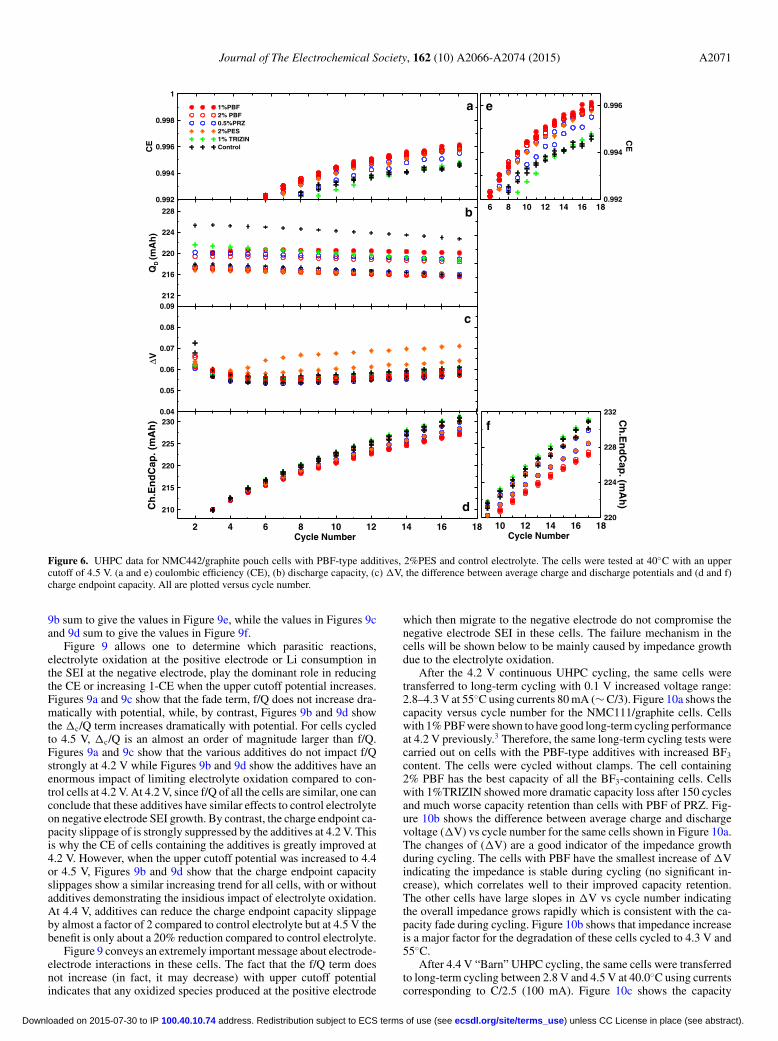
Cells with the same electrolyte additives considered in Figures 4and 5 have been tested to even higher potential. Figure 6a shows theCE versus cycle number of the cells continuously cycled at C/20 be-tween 2.8 and 4.5 V at 40. ± 0.1◦C. The CE values in Figure 6 (4.5 Vcontinuous cycling) are much lower than those for cells with the sameadditives shown in Figures 4 (4.2 V continuous) and 5 (4.4 V “barn”)indicating severe electrolyte oxidation at high potential. Cells withPBF showed a higher CE than cells with PRZ or TRIZIN. At 4.5 V,
cells with 0.5% PRZ cells have similar CE to cells with 2% PES.Figure 6c shows that �V for all cells increases with cycling indicat-ing an overall impedance growth during charge-discharge testing to4.5 V. Figure 6d shows the charge endpoint capacity of the cells.Figure 6d shows that when the upper cutoff increases to 4.5 V, thefractional benefit of the additives is much smaller than at 4.2 or 4.4 V.
After the cycling tests at 4.2, 4.4 and 4.5 V using the UHPC, EISspectra of the cells described in Figure 7 were measured at 3.8 Vand 10. ± 0.1◦C. Figures 7a and 7b show the Nyquist plots of theimpedance spectra of the pouch cells described by Figure 4. Theimpedance (Rct) of the cells containing control electrolyte increasedafter cycling, while those with 2% PBF decreased after cycling, whichis consistent with the �V data shown in Figure 4c. The impedancespectra of the other cells with additives were virtually unchangedbefore and after cycling for 16 cycles at 40◦C to 4.2 V at C/20.Figures 7c and 7d show the Nyquist plots of the impedance spec-tra of the pouch cells described by Figure 5 before and after 4.4 V“barn” UHPC cycling at 40◦C. The diameter of the semi-circle in theimpedance spectrum represents the sum of the resistive parts of thecharge transfer impedance and the transfer of ions through the SEIlayers for both electrodes. The cells with control electrolyte showedsignificant impedance growth after cycling and the semicircle distorted
) unless CC License in place (see abstract). ecsdl.org/site/terms_use address. Redistribution subject to ECS terms of use (see 100.40.10.74Downloaded on 2015-07-30 to IP

A2070 Journal of The Electrochemical Society, 162 (10) A2066-A2074 (2015)
0.99
0.992
0.994
0.996
0.998
1
CE
1%PBF2%PBF0.5%PRZ1% TRIZIN2%PESControl
232
236
240
244
248
QD
(mA
h)
2 4 6 8 10 12 14 16Cycle Number
240
250
260
Ch
.En
dC
ap
.(m
Ah
)
0.03
0.04
0.05
0.06
ΔV
2 4 6 8 10 12 14 16
1%PBF2%PBF0.5%PRZ1% TRIZIN2%PESControl
0.994
0.995
0.996
0.997
0.998
CE
a
b
c
d
e
Figure 5. UHPC data for NMC442/graphite pouch cells with PBF-type additives, 2%PES and control electrolyte. The cells were tested at 40◦C with an uppercutoff of 4.4 V using the “barn” cycling protocol described in Figure 2. (a and e) columbic efficiency (CE), (b) discharge capacity, (c) �V, the difference betweenaverage charge and discharge potentials and (d) charge endpoint capacity. All are plotted versus cycle number.
significantly into two semicircles. The increase of the low frequencysemicircle is due to an increase of the charge transfer resistance of thepositive electrode, consistent with the previous report of Ma et al.6
The cell with 2% PES showed a decrease in Rct after these 16 cycleswhich is also consistent with Ma et al.6 All cells containing PBF, PRZor TRIZIN showed little change to their impedance spectra before andafter cycling. Again, Figures 7e and 7f show the Nyquist plots of theimpedance spectra of the pouch cells described by Figure 6 before andafter 4.5 V continuous UHPC cycling at 40◦C. The impedance spectraof all the cells were distorted from one semicircle to two distinguish-able semicircles suggesting the growth of the cathode charge transferimpedance during high voltage cycling. The impedance of all cells,except those with 2% PES and 0.5%PRZ, increased significantly afterthe cycling to 4.5 V, consistent with the growth of �V during thecycling.
Figure 8 shows a summary of the gas evolution of the cells afterUHPC cycling to the three different upper cutoff potentials (Figures4, 5 and 6). The gas generated in all cells was quite small, less than5% of the initial pouch cell volume (2.2 mL). In fact, cells cycled to4.2 V showed virtually no expansion at all. To put the amount of gasgenerated into perspective, Figure S3 shows a freshly vacuum-sealedpouch cell and a pouch cell that has expanded by 0.1 mL (5%). Thereis no visible difference.
Smith et al. consider how coulombic efficiency, charge end pointcapacity slippage and capacity fade are related.15 Equations 11–14 inthat paper can be rewritten (in the case where there is no positive elec-
trode damage and no reduction of salt concentration in the electrolyte)as:
1 − CE = f/Q + �c/Q [2]
where f is the capacity loss per cycle (in mAh/cycle), �c is the chargeend point capacity slippage per cycle (in mAh/cycle) and Q is thecell capacity (in mAh). Table III compares 1- CE, f/Q and �c/Q forthe UHPC measurements on all cells with the various additives testedto upper cutoff potentials of 4.2 V (Figure 4), 4.4 V (Figure 5) and4.5 V (Figure 6). The measurements of f/Q in Table III were takenfrom the slopes of the last 5 data points in Figures 4b, 5b and 6b. Themeasurements of �c/Q in Table III were taken from the slopes of thelast 5 data points in Figures 4d, 5d and 6d. The measured values of1 – CE in Table III were taken by averaging the last 3 data points inFigures 4e, 5e and 6e. The calculated values of 1-CE in Table III wereobtained using Equation 2.
Figure 9 displays the results of Table III. Figures 9a and 9c showthe fraction of capacity loss per cycle and the fraction of capacity lostper hour, respectively. This capacity loss represents Li atoms whichaccumulate in the thickening negative electrode SEI. Figures 9b and9d show the fraction of capacity by which the charge endpoint slipseach cycle and the fraction of capacity by which the charge end pointslips each hour. This charge endpoint capacity slippage is primarilycaused by electrolyte oxidation. Figures 9e and 9f show 1 - CE and (1– CE)/(time of one cycle), respectively. The values in Figures 9a and
) unless CC License in place (see abstract). ecsdl.org/site/terms_use address. Redistribution subject to ECS terms of use (see 100.40.10.74Downloaded on 2015-07-30 to IP
Journal of The Electrochemical Society, 162 (10) A2066-A2074 (2015) A2071
0.992
0.994
0.996
0.998
1
CE
1%PBF2% PBF0.5%PRZ2%PES1% TRIZINControl
212
216
220
224
228
QD
(mA
h)
2 4 6 8 10 12 14 16 18Cycle Number
210
215
220
225
230
Ch
.En
dC
ap.(
mA
h)
0.04
0.05
0.06
0.07
0.08
0.09
Δ V
6 8 10 12 14 16 180.992
0.994
0.996
CE
10 12 14 16 18Cycle Number
220
224
228
232 Ch
.En
dC
ap. (m
Ah
)
a
b
c
d
e
f
Figure 6. UHPC data for NMC442/graphite pouch cells with PBF-type additives, 2%PES and control electrolyte. The cells were tested at 40◦C with an uppercutoff of 4.5 V. (a and e) coulombic efficiency (CE), (b) discharge capacity, (c) �V, the difference between average charge and discharge potentials and (d and f)charge endpoint capacity. All are plotted versus cycle number.
9b sum to give the values in Figure 9e, while the values in Figures 9cand 9d sum to give the values in Figure 9f.
Figure 9 allows one to determine which parasitic reactions,electrolyte oxidation at the positive electrode or Li consumption inthe SEI at the negative electrode, play the dominant role in reducingthe CE or increasing 1-CE when the upper cutoff potential increases.Figures 9a and 9c show that the fade term, f/Q does not increase dra-matically with potential, while, by contrast, Figures 9b and 9d showthe �c/Q term increases dramatically with potential. For cells cycledto 4.5 V, �c/Q is an almost an order of magnitude larger than f/Q.Figures 9a and 9c show that the various additives do not impact f/Qstrongly at 4.2 V while Figures 9b and 9d show the additives have anenormous impact of limiting electrolyte oxidation compared to con-trol cells at 4.2 V. At 4.2 V, since f/Q of all the cells are similar, one canconclude that these additives have similar effects to control electrolyteon negative electrode SEI growth. By contrast, the charge endpoint ca-pacity slippage of is strongly suppressed by the additives at 4.2 V. Thisis why the CE of cells containing the additives is greatly improved at4.2 V. However, when the upper cutoff potential was increased to 4.4or 4.5 V, Figures 9b and 9d show that the charge endpoint capacityslippages show a similar increasing trend for all cells, with or withoutadditives demonstrating the insidious impact of electrolyte oxidation.At 4.4 V, additives can reduce the charge endpoint capacity slippageby almost a factor of 2 compared to control electrolyte but at 4.5 V thebenefit is only about a 20% reduction compared to control electrolyte.
Figure 9 conveys an extremely important message about electrode-electrode interactions in these cells. The fact that the f/Q term doesnot increase (in fact, it may decrease) with upper cutoff potentialindicates that any oxidized species produced at the positive electrode
which then migrate to the negative electrode do not compromise thenegative electrode SEI in these cells. The failure mechanism in thecells will be shown below to be mainly caused by impedance growthdue to the electrolyte oxidation.
After the 4.2 V continuous UHPC cycling, the same cells weretransferred to long-term cycling with 0.1 V increased voltage range:2.8–4.3 V at 55◦C using currents 80 mA (∼ C/3). Figure 10a shows thecapacity versus cycle number for the NMC111/graphite cells. Cellswith 1% PBF were shown to have good long-term cycling performanceat 4.2 V previously.3 Therefore, the same long-term cycling tests werecarried out on cells with the PBF-type additives with increased BF3
content. The cells were cycled without clamps. The cell containing2% PBF has the best capacity of all the BF3-containing cells. Cellswith 1%TRIZIN showed more dramatic capacity loss after 150 cyclesand much worse capacity retention than cells with PBF of PRZ. Fig-ure 10b shows the difference between average charge and dischargevoltage (�V) vs cycle number for the same cells shown in Figure 10a.The changes of (�V) are a good indicator of the impedance growthduring cycling. The cells with PBF have the smallest increase of �Vindicating the impedance is stable during cycling (no significant in-crease), which correlates well to their improved capacity retention.The other cells have large slopes in �V vs cycle number indicatingthe overall impedance grows rapidly which is consistent with the ca-pacity fade during cycling. Figure 10b shows that impedance increaseis a major factor for the degradation of these cells cycled to 4.3 V and55◦C.
After 4.4 V “Barn” UHPC cycling, the same cells were transferredto long-term cycling between 2.8 V and 4.5 V at 40.0◦C using currentscorresponding to C/2.5 (100 mA). Figure 10c shows the capacity
) unless CC License in place (see abstract). ecsdl.org/site/terms_use address. Redistribution subject to ECS terms of use (see 100.40.10.74Downloaded on 2015-07-30 to IP

A2072 Journal of The Electrochemical Society, 162 (10) A2066-A2074 (2015)
20
40
60
80
100
-Zj(
Ω. c
m2 )
0.5%PRZ1% PBF2%PBF1%TRIZIN2% VCControl
a bBefore After
20
40
60
80
-Zj(
Ω. c
m2 )
0.5%PRZ1%PBF2%PBF1%TRIZIN2%PESControl
c d
0 40 80 120 160 200
Zr (Ω .cm2 )
0
20
40
60
80
-Zj(
Ω. c
m2 )
0 40 80 120 160 200
Zr (Ω.cm2)
e f
Figure 7. Nyquist plots of the impedance spectra of the cells before and afterUHPC at different voltages. (a) The cells described on Figure 4: before UHPCcycled at 4.2 V, and (b) after UHPC cycled at 4.2 V, (c) the cells described inFigure 5: before UHPC cycled at 4.4 V, (d) after UHPC cycled at 4.4 V, (e)the cells described in Figure 6: before UHPC cycled at 4.5 V, (f) after UHPCcycled at 4.5 V.
versus cycle number for the unclamped NMC442/graphite pouch cellswith BF3-containing additives along with comparative cells includingcontrol and cells with 2% PES. The control cells have quite poorperformance during this high voltage cycling. Cells with 2%PES startto show large capacity fade after 200 cycles. Cells with 1%PBF or0.5%PRZ have better capacity retention than cells with 1%TRIZINand reach 80% of initial capacity after about 400 cycles. Figure 10dshows the difference between average charge and discharge voltage(�V) vs. cycle number for the same cells shown in Figure 10c. The
0.02
0.04
0.06
0.08
0.1
0.5%PRZ
1%PBF
2%PBF
1%TRIZIN
2%PES
control
-0.06
-0.04
-0.02
0
0.02
Gas
Vo
lum
e(m
L)
2%V
C
Additives0
0.02
0.04
0.06
0.08
0.1
0.5%PRZ
1%PBF2%PBF
1%TRIZIN
2%PES
control
Co
ntr
ol
1%T
RIZ
IN
2 %P
BF
1%P
BF
0.5%
PR
Z
a
b
c
4.2V
4.4V
4.5V
Figure 8. Summary of volume expansion of pouch cells after the UHPCcycling presented in Figures 4, 5 and 6. a) cells cycled to 4.2 V; b) cells cycledto 4.4 V; c) cells cycled to 4.5 V.
large �V changes indicate the impedance increase of the cells. Thereis rapid capacity fading during the 4.5 V cycling compared to the 4.3V, 55◦C cycling (Figure 10a).
From both the charge endpoint capacity slippage results for thecells as shown in Figure 9b and the changes in �V (overall impedancechange) shown in Figures 10b and 10d, cells containing 2% PBFshowed the smallest charge endpoint capacity slippage at differentvoltages implying less electrolyte oxidation at cathode surface up to4.5 V and the slowest impedance growth during long-term cycling.It is our opinion that the electrolyte oxidation is the root cause ofthe impedance growth, so limiting charge endpoint capacity slippageleads to less impedance growth and better charge-discharge cyclingperformance.
Figures S4 and S5 show the impedance spectra (measured at 3.8 Vand 10.◦C) and gas volume generated in the cells displayed in Figures
Table III. 1-CE, fraction of capacity loss/cycle (f/Q) and fraction of charge endpoint capacity slippage/cycle (�c/Q) calculated from 4.2, 4.4 and4.5 V UHPC data of the cells with different electrolytes.
1%PBF 2%PBF 0.5%PRZ
1-CEMea f/Q �c/Q 1-CEMea f/Q �c/Q 1-CEMea f/Q �c/Q
4.2 V 0.0019 0.000727 0.001136 0.0018 0.000834 0.00095 0.002 0.000807 0.0011134.4 V 0.0032 0.000292 0.002708 0.0029 0.000245 0.002781 0.0033 0.000345 0.0030464.5 V 0.0044 0.000455 0.004000 0.0045 0.000386 0.004182 0.005 0.000459 0.004582
1%TRIZIN Control 2%PES
1-CEMea f/Q �c/Q 1-CEMea f/Q �c/Q 1-CEMea f/Q �c/Q4.2 V 0.0023 0.000854 0.00143 0.0055 0.00082 0.0046474.4 V 0.0042 0.000719 0.003961 0.0046 0.00047 0.004023 0.0037 0.00011 0.0036504.5 V 0.0058 0.000847 0.005083 0.0058 0.000869 0.005068 0.0049 0.00025 0.004718
) unless CC License in place (see abstract). ecsdl.org/site/terms_use address. Redistribution subject to ECS terms of use (see 100.40.10.74Downloaded on 2015-07-30 to IP

Journal of The Electrochemical Society, 162 (10) A2066-A2074 (2015) A2073
0
0.0002
0.0004
0.0006
0.0008
0.001
Fad
e/Q
(F
ract
ion
of
Cp
acit
y/C
ycle
)
1%PBF2%PBF0.5%PRZ1%TRIZIN2%PESControl
0
0.001
0.002
0.003
0.004
0.005
Slip
pag
e/Q
(F
ract
ion
of
Slip
pag
e/C
ycle
)
4.1 4.2 4.3 4.4 4.5 4.6Voltage (V)
0
0.002
0.004
0.006
0.008
1-C
E
1-CEMea_1%PBF1-CECal
1-CEMea_2%PBF1-CECal
1-CEMea_0.5%PRZ1-CECal
1-CEMea_1%TRIZIN1-CECal
1-CEMea_2%PES1-CECal
1-CEMea_Control1-CECal
1E-005
2E-005
3E-005 Fad
e/h.Q
(F
raction
of C
pacity/h
)
0
5E-005
0.0001
0.00015 Slip
pag
e/h.Q
(F
raction
of S
lipp
age/h
)
a
b
c
d
e
4.1 4.2 4.3 4.4 4.5 4.6Voltage (V)
0
4E-005
8E-005
0.00012
0.00016
1-CE
/h
f
Figure 9. Summary of the (a) fraction of capacity fade/cycle, f/Q; (b) fraction of capacity by which the charge endpoint slips each cycle, �c/Q; (c) fractionof capacity fade/hour, f/(Q•time of a cycle); (d) fraction of capacity by which the charge end point slips each hour, �c/(Q•time of a cycle); (e) 1-CE and (f)1-CE/(time of a cycle) of the cells tested in the different voltage ranges using the UHPC.
140
160
180
200
220
Dis
char
ge
Cap
acit
y (m
Ah
)
1%PBF2%PBF0.5%PRZ1%TRIZINControl
2.8-4.3V, 55oC, 80mA
0 200 400 600Cycle Number
40
80
120
160
ΔV (
mV
)
2.8-4.3V, 55oC, 80mA
a
b
1%PBF0.5%PRZ1%TRIZIN2%PESControl
140
160
180
200
220
240
260
Disch
arge C
apacity (m
Ah
)
2.8-4.5V, 40oC, C/2.5
100 200 300 400 500Cycle Number
100
200
300
400
500
ΔV
(mV
)
c
d
Figure 10. (a) Discharge capacity versus cycle number for NMC111/graphite pouch cells cycled without clamps at C/3 (0.08 A) at 55. ± 0.1◦C between 2.8 and4.3 V with different additives and control electrolyte, (b) difference between average charge and discharge voltage (delta V) of the same cells, all plotted versuscycle number, (c) discharge capacity versus cycle number for NMC442/graphite pouch cells cycled without clamps at C/2.5 (0.1 A) at 40. ± 0.1◦C between 2.8and 4.5 V with different additives and control electrolyte. A C/20 cycle was included every 50 cycles, (d) difference between average charge and discharge voltage(delta V) of the same cells, all plotted versus cycle number.
) unless CC License in place (see abstract). ecsdl.org/site/terms_use address. Redistribution subject to ECS terms of use (see 100.40.10.74Downloaded on 2015-07-30 to IP

A2074 Journal of The Electrochemical Society, 162 (10) A2066-A2074 (2015)
10c and 10d after 500 cycles. The cell with control electrolyte showsa significant gas production and impedance growth during cyclingwhile the cells with other additives show much less gas evolutionand impedance growth. This reduction in gas production, which helpsmaintain stack pressure on the electrodes in the cells, is why the cellswith TRIZIN, which have similar charge endpoint capacity slippageand coulombic efficiency to control cells (see Figure 9) have muchbetter capacity retention than control cells.
Conclusions
Pyridine-Boron Trifluoride, Pyrazine-(BF3)2 and Triazine-(BF3)3
are easily synthesized using similar synthesis reactions. The addi-tives were evaluated using various experiments including UHPC,impedance, gas measurements and long-term cycling in different po-tential ranges. These additives suppress impedance growth. The com-parisons between PBF, PRZ and TRIZIN indicate that cells with PBFhad the highest CE and the smallest charge endpoint capacity slippagein every voltage range for both NMC111 and NMC442 type cells.0.5% PRZ has comparable effects to 1% PBF. Cells with 1%TRIZINcells showed quite low CE and large charge endpoint capacity slippageat every voltage so the effects of PBF-type additives are not simplyimproved by increasing the ratio of BF3 in the molecules. Addition-ally, the type of Lewis base may also be very important. PBF, with thesimplest structure, outperforms the other derivatives.
When the upper cutoff potential was increased, the charge end-point capacity slippages (�c/Q, the dominant term) showed a similarincreasing trend for all cells suggesting the benefits of additives insuppressing electrolyte oxidation is limited at the highest voltages(4.4 V and 4.5 V). The similar electrolyte oxidation (with/ withoutadditives) which occurs at 4.5 V on the cathode surface is caused bythe oxidation of carbonate solvents. Although PBF performed as avery promising additive, alternative solvents may be required to sig-
nificantly reduce the charge endpoint capacity slippage and improvethe capacity retention during cycling to 4.5 V.
Acknowledgments
The authors acknowledge the financial support of NSERC and 3 MCanada under the auspices of the Industrial Research Chairs programand the funding of NSERC under the Automotive Partnership Canadaprogram. The authors thank Dr. Jing Li of BASF for providing someof the solvents and salts used in this work.
References
1. M. Armand and J.-M. Tarascon, Nature, 451, 652 (2008).2. J. B. Goodenough and K.-S. Park, J. Am. Chem. Soc., 135, 1167 (2013).3. M. Nie, J. Xia, and J. R. Dahn, J. Electrochem. Soc., 162, A1186 (2015).4. N. P. W. Pieczonka, L. Yang, M. P. Balogh, B. R. Powell, K. chemelewski,
A. Manthiram, S. A. Kracgkovskiy, G. R. Goward, M. Liu, and J.-H. Kim, J. Phys.Chem. C, 117, 22603 (2013).
5. C. L. Campion, W. Li, and B. L. Lucht, J. Electrochem. Soc., 152, A2327(2005).
6. L. Ma, J. Xia, and J. R. Dahn, J. Electrochem. Soc., 161, A2250 (2014).7. X. Zuo, C. Fan, J. Liu, X. Xiao, J. Wu, and J. Nan, J. Electrochem. Soc., 160, A1199
(2013).8. P. A. van der Meulen and H. A. Heller, J. Am. Chem. Soc., 54, 4404 (1932).9. C. A. Wamser, J. Am. Chem. Soc. 73, 409 (1951).
10. C. Laurence and J.-F. Gal, Lewis Basicity and Affinity Scales, John Wiley & Sons,Ltd. (2009).
11. T. M. Bond, J. C. Burns, D. A. Stevens, H. M. Dahn, and J. R. Dahn, J. Electrochem.Soc., 160, A521 (2013).
12. C. P. Aiken, J. Xia, D. Y. Wang, D. A. Stevens, S. Trussler, and J. R. Dahn, J. Elec-trochem. Soc., 161, A1548 (2014).
13. J. Xia, C. P. Aiken, L. Ma, G. Y. Kim, J. C. Burns, L. P. Chen, and J. R. Dahn, J.Electrochem. Soc., 161, A1149 (2014).
14. M. Nie, J. Xia, and J. R. Dahn, J Electrochem. Soc., 162(8) X17 (2015).15. A. J. Smith, J. C. Burns, D. Xiong, and J. R. Dahn, J Electrochem. Soc., 158, A1136
(2011).
) unless CC License in place (see abstract). ecsdl.org/site/terms_use address. Redistribution subject to ECS terms of use (see 100.40.10.74Downloaded on 2015-07-30 to IP
Related Documents
![Rotational Ligand Dynamics in Mn[N(CN) 2 ] 2 .pyrazine](https://static.cupdf.com/doc/110x72/56815d96550346895dcbb50b/rotational-ligand-dynamics-in-mnncn-2-2-pyrazine.jpg)