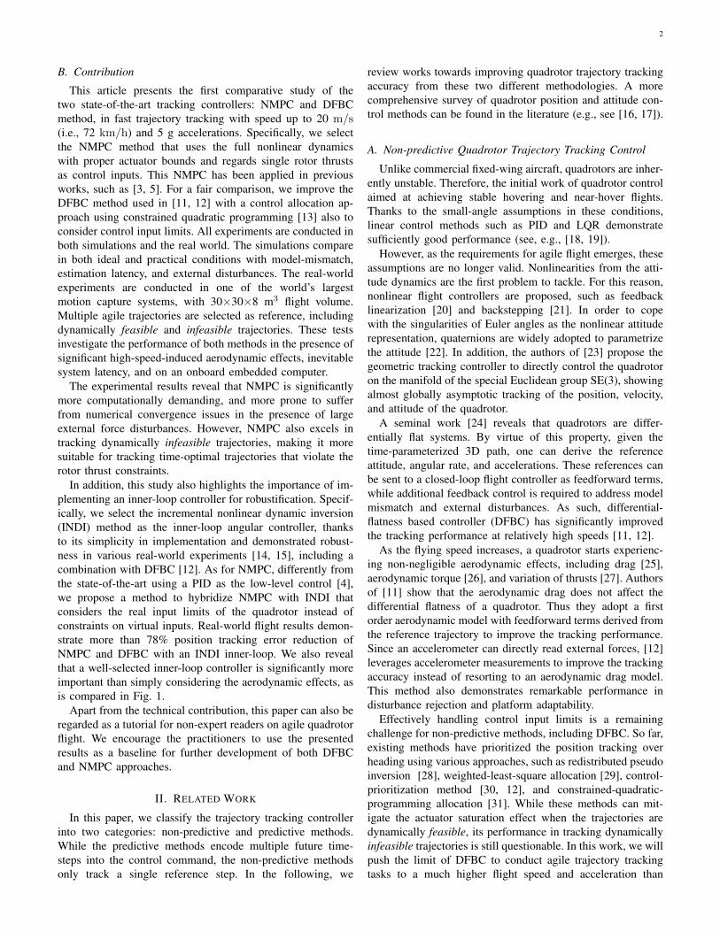
1 A Comparative Study of Nonlinear MPC and Differential-Flatness-Based Control for Quadrotor Agile Flight Sihao Sun, Angel Romero, Philipp Foehn, Elia Kaufmann and Davide Scaramuzza Abstract—Accurate trajectory tracking control for quadrotors is essential for safe navigation in cluttered environments. How- ever, this is challenging in agile flights due to nonlinear dy- namics, complex aerodynamic effects, and actuation constraints. In this article, we empirically compare two state-of-the-art control frameworks: the nonlinear-model-predictive controller (NMPC) and the differential-flatness-based controller (DFBC), by tracking a wide variety of agile trajectories at speeds up to 72 km/h. The comparisons are performed in both simulation and real-world environments to systematically evaluate both methods from the aspect of tracking accuracy, robustness, and computational efficiency. We show the superiority of NMPC in tracking dynamically infeasible trajectories, at the cost of higher computation time and risk of numerical convergence issues. For both methods, we also quantitatively study the effect of adding an inner-loop controller using the incremental nonlinear dynamic inversion (INDI) method, and the effect of adding an aerodynamic drag model. Our real-world experiments, performed in one of the world’s largest motion capture systems, demonstrate more than 78% tracking error reduction of both NMPC and DFBC, indicating the necessity of using an inner-loop controller and aerodynamic drag model for agile trajectory tracking. Video of the experiments: https://youtu.be/XpuRpKHp Bk I. I NTRODUCTION A. Motivation Quadrotors are extremely agile. Exploiting their agility is crucial for time-critical missions, such as search and rescue, aerial delivery, drone racing, and even flying cars [1, 2]. An accurate trajectory tracking controller is required to safely ex- ecute high-speed trajectories in cluttered environments. How- ever, most approaches struggle to handle joint effects in agile flights, such as nonlinear dynamics, aerodynamic effects, and actuation limits. Recently, nonlinear model predictive control (NMPC) has drawn much attention for quadrotor control thanks to advances in hardware and algorithmic efficiency [3–10]. NMPC par- ticularly excels in handling control limits, and its predictive nature is believed to be beneficial for trajectory tracking at high speeds [3]. A recent study has demonstrated its performance in tracking aggressive trajectories up to 20 m/s [4]. All authors are with the Robotics and Perception Group, University of Zurich, Switzerland (http://rpg.ifi.uzh.ch). This work was supported by the National Centre of Competence in Research (NCCR) Robotics through the Swiss National Science Foundation (SNSF) and the European Union’s Horizon 2020 Research and Innovation Programme under grant agreement No. 871479 (AERIAL-CORE) and the European Research Council (ERC) under grant agreement No. 864042 (AGILEFLIGHT). Fig. 1: Top: One quadrotor tracking a race trajectory. Bottom: Box plot comparing the position tracking root-mean-square-error (RMSE) of NMPC, DFBC, and their variations with INDI inner-loop, and aerodynamic drag model. For each method, data are collected from real-world flights tracking different reference trajectories with speeds up to 72 km/h and accelerations up to 5g. Outliers of DFBC+INDI (with drag) and NMPC+INDI (with drag) represent the position RMSE when tracking dynamically infeasible trajectories. However, NMPC is computationally extremely demanding compared to the state-of-the-art non-predictive method: the differential-flatness-based controller (DFBC) [11, 12]. This method also shows great potential in accurately tracking agile trajectories autonomously. A recent study has used DFBC to track trajectories up to 12.9 m/s with 2.1 g accelerations, with only 6.6 centimeters position tracking error [12]. Although the state-of-the-art DFBC has not achieved agile flights as fast as NMPC showed in [4], its high computational efficiency and tracking accuracy render the necessity of applying NMPC for agile trajectory tracking questionable. Therefore, a compara- tive study of NMPC and DFBC is needed to provide insights for future research on fully autonomous agile flights, in order to further improve their efficiency and reliability.

Welcome message from author
This document is posted to help you gain knowledge. Please leave a comment to let me know what you think about it! Share it to your friends and learn new things together.
Transcript

1
A Comparative Study of Nonlinear MPC andDifferential-Flatness-Based Control for Quadrotor
Agile FlightSihao Sun, Angel Romero, Philipp Foehn, Elia Kaufmann and Davide Scaramuzza
Abstract—Accurate trajectory tracking control for quadrotorsis essential for safe navigation in cluttered environments. How-ever, this is challenging in agile flights due to nonlinear dy-namics, complex aerodynamic effects, and actuation constraints.In this article, we empirically compare two state-of-the-artcontrol frameworks: the nonlinear-model-predictive controller(NMPC) and the differential-flatness-based controller (DFBC),by tracking a wide variety of agile trajectories at speeds up to72 km/h. The comparisons are performed in both simulationand real-world environments to systematically evaluate bothmethods from the aspect of tracking accuracy, robustness, andcomputational efficiency. We show the superiority of NMPC intracking dynamically infeasible trajectories, at the cost of highercomputation time and risk of numerical convergence issues. Forboth methods, we also quantitatively study the effect of addingan inner-loop controller using the incremental nonlinear dynamicinversion (INDI) method, and the effect of adding an aerodynamicdrag model. Our real-world experiments, performed in one ofthe world’s largest motion capture systems, demonstrate morethan 78% tracking error reduction of both NMPC and DFBC,indicating the necessity of using an inner-loop controller andaerodynamic drag model for agile trajectory tracking.
Video of the experiments: https://youtu.be/XpuRpKHp Bk
I. INTRODUCTION
A. Motivation
Quadrotors are extremely agile. Exploiting their agility iscrucial for time-critical missions, such as search and rescue,aerial delivery, drone racing, and even flying cars [1, 2]. Anaccurate trajectory tracking controller is required to safely ex-ecute high-speed trajectories in cluttered environments. How-ever, most approaches struggle to handle joint effects in agileflights, such as nonlinear dynamics, aerodynamic effects, andactuation limits.
Recently, nonlinear model predictive control (NMPC) hasdrawn much attention for quadrotor control thanks to advancesin hardware and algorithmic efficiency [3–10]. NMPC par-ticularly excels in handling control limits, and its predictivenature is believed to be beneficial for trajectory tracking at highspeeds [3]. A recent study has demonstrated its performancein tracking aggressive trajectories up to 20 m/s [4].
All authors are with the Robotics and Perception Group, University ofZurich, Switzerland (http://rpg.ifi.uzh.ch). This work was supported by theNational Centre of Competence in Research (NCCR) Robotics through theSwiss National Science Foundation (SNSF) and the European Union’s Horizon2020 Research and Innovation Programme under grant agreement No. 871479(AERIAL-CORE) and the European Research Council (ERC) under grantagreement No. 864042 (AGILEFLIGHT).
Fig. 1: Top: One quadrotor tracking a race trajectory. Bottom: Boxplot comparing the position tracking root-mean-square-error (RMSE)of NMPC, DFBC, and their variations with INDI inner-loop, andaerodynamic drag model. For each method, data are collected fromreal-world flights tracking different reference trajectories with speedsup to 72 km/h and accelerations up to 5g. Outliers of DFBC+INDI(with drag) and NMPC+INDI (with drag) represent the positionRMSE when tracking dynamically infeasible trajectories.
However, NMPC is computationally extremely demandingcompared to the state-of-the-art non-predictive method: thedifferential-flatness-based controller (DFBC) [11, 12]. Thismethod also shows great potential in accurately tracking agiletrajectories autonomously. A recent study has used DFBC totrack trajectories up to 12.9 m/s with 2.1 g accelerations, withonly 6.6 centimeters position tracking error [12]. Although thestate-of-the-art DFBC has not achieved agile flights as fast asNMPC showed in [4], its high computational efficiency andtracking accuracy render the necessity of applying NMPC foragile trajectory tracking questionable. Therefore, a compara-tive study of NMPC and DFBC is needed to provide insightsfor future research on fully autonomous agile flights, in orderto further improve their efficiency and reliability.
2
B. Contribution
This article presents the first comparative study of thetwo state-of-the-art tracking controllers: NMPC and DFBCmethod, in fast trajectory tracking with speed up to 20 m/s(i.e., 72 km/h) and 5 g accelerations. Specifically, we selectthe NMPC method that uses the full nonlinear dynamicswith proper actuator bounds and regards single rotor thrustsas control inputs. This NMPC has been applied in previousworks, such as [3, 5]. For a fair comparison, we improve theDFBC method used in [11, 12] with a control allocation ap-proach using constrained quadratic programming [13] also toconsider control input limits. All experiments are conducted inboth simulations and the real world. The simulations comparein both ideal and practical conditions with model-mismatch,estimation latency, and external disturbances. The real-worldexperiments are conducted in one of the world’s largestmotion capture systems, with 30×30×8 m3 flight volume.Multiple agile trajectories are selected as reference, includingdynamically feasible and infeasible trajectories. These testsinvestigate the performance of both methods in the presence ofsignificant high-speed-induced aerodynamic effects, inevitablesystem latency, and on an onboard embedded computer.
The experimental results reveal that NMPC is significantlymore computationally demanding, and more prone to sufferfrom numerical convergence issues in the presence of largeexternal force disturbances. However, NMPC also excels intracking dynamically infeasible trajectories, making it moresuitable for tracking time-optimal trajectories that violate therotor thrust constraints.
In addition, this study also highlights the importance of im-plementing an inner-loop controller for robustification. Specif-ically, we select the incremental nonlinear dynamic inversion(INDI) method as the inner-loop angular controller, thanksto its simplicity in implementation and demonstrated robust-ness in various real-world experiments [14, 15], including acombination with DFBC [12]. As for NMPC, differently fromthe state-of-the-art using a PID as the low-level control [4],we propose a method to hybridize NMPC with INDI thatconsiders the real input limits of the quadrotor instead ofconstraints on virtual inputs. Real-world flight results demon-strate more than 78% position tracking error reduction ofNMPC and DFBC with an INDI inner-loop. We also revealthat a well-selected inner-loop controller is significantly moreimportant than simply considering the aerodynamic effects, asis compared in Fig. 1.
Apart from the technical contribution, this paper can also beregarded as a tutorial for non-expert readers on agile quadrotorflight. We encourage the practitioners to use the presentedresults as a baseline for further development of both DFBCand NMPC approaches.
II. RELATED WORK
In this paper, we classify the trajectory tracking controllerinto two categories: non-predictive and predictive methods.While the predictive methods encode multiple future time-steps into the control command, the non-predictive methodsonly track a single reference step. In the following, we
review works towards improving quadrotor trajectory trackingaccuracy from these two different methodologies. A morecomprehensive survey of quadrotor position and attitude con-trol methods can be found in the literature (e.g., see [16, 17]).
A. Non-predictive Quadrotor Trajectory Tracking Control
Unlike commercial fixed-wing aircraft, quadrotors are inher-ently unstable. Therefore, the initial work of quadrotor controlaimed at achieving stable hovering and near-hover flights.Thanks to the small-angle assumptions in these conditions,linear control methods such as PID and LQR demonstratesufficiently good performance (see, e.g., [18, 19]).
However, as the requirements for agile flight emerges, theseassumptions are no longer valid. Nonlinearities from the atti-tude dynamics are the first problem to tackle. For this reason,nonlinear flight controllers are proposed, such as feedbacklinearization [20] and backstepping [21]. In order to copewith the singularities of Euler angles as the nonlinear attituderepresentation, quaternions are widely adopted to parametrizethe attitude [22]. In addition, the authors of [23] propose thegeometric tracking controller to directly control the quadrotoron the manifold of the special Euclidean group SE(3), showingalmost globally asymptotic tracking of the position, velocity,and attitude of the quadrotor.
A seminal work [24] reveals that quadrotors are differ-entially flat systems. By virtue of this property, given thetime-parameterized 3D path, one can derive the referenceattitude, angular rate, and accelerations. These references canbe sent to a closed-loop flight controller as feedforward terms,while additional feedback control is required to address modelmismatch and external disturbances. As such, differential-flatness based controller (DFBC) has significantly improvedthe tracking performance at relatively high speeds [11, 12].
As the flying speed increases, a quadrotor starts experienc-ing non-negligible aerodynamic effects, including drag [25],aerodynamic torque [26], and variation of thrusts [27]. Authorsof [11] show that the aerodynamic drag does not affect thedifferential flatness of a quadrotor. Thus they adopt a firstorder aerodynamic model with feedforward terms derived fromthe reference trajectory to improve the tracking performance.Since an accelerometer can directly read external forces, [12]leverages accelerometer measurements to improve the trackingaccuracy instead of resorting to an aerodynamic drag model.This method also demonstrates remarkable performance indisturbance rejection and platform adaptability.
Effectively handling control input limits is a remainingchallenge for non-predictive methods, including DFBC. So far,existing methods have prioritized the position tracking overheading using various approaches, such as redistributed pseudoinversion [28], weighted-least-square allocation [29], control-prioritization method [30, 12], and constrained-quadratic-programming allocation [31]. While these methods can mit-igate the actuator saturation effect when the trajectories aredynamically feasible, its performance in tracking dynamicallyinfeasible trajectories is still questionable. In this work, we willpush the limit of DFBC to conduct agile trajectory trackingtasks to a much higher flight speed and acceleration than

3
the state-of-the-art, and study its performance in trackingdynamically infeasible trajectories where violating rotor thrustlimits becomes inevitable.
B. Model Predictive Control for Quadrotor Trajectory Track-ing
Model predictive control (MPC) is a prevalent method inrobots thanks to its predictive nature and ability to handle inputconstraints[10, 32]. It generates control commands in recedinghorizon fashion, which minimizes the tracking error in thepredicted time horizon by solving constrained optimizationproblems.
However, MPC is very computationally demandingcompared with non-predictive methods. Especially, usingnonlinear-MPC (NMPC) with a full-state nonlinear model ofa quadrotor was computationally intractable onboard early-age unmanned-aerial vehicles (UAVs). For this reason, linear-MPC (LMPC) is adopted in many studies for only positioncontrol [33], or control linearized model based on small-angle assumptions [34]. Therefore, these LMPC methodscannot fully capture nonlinearities in rotational dynamics, andunderperforms NMPC methods [10, 32]
Separating flight controllers into high-level position controland low-level attitude control is another common approachto simplify the model and alleviate the computational loadof NMPC [6, 7, 9]. However, in such a cascaded controlarchitecture, the high-level controller cannot precisely capturethe real quadrotor capability because they often ignore theeffects of system limitation (such as [6]), or introduce a virtualconstraint on states [9]. Consequently, the command fed intothe lower-level controller is either too conservative to achieveagile flights, or over-aggressive that causes instability.
Thanks to the recent development in hardware and nonlinearoptimization solvers [35–37], running NMPC with a nonlinearfull dynamic model becomes computationally tractable on anembedded computer. Hence, recently, some studies start usingthe full-nonlinear dynamic model, and regarding single rotorthrusts as inputs for NMPC, thus are able to fully exploitquadrotors capability [3–5]. These methods either directlyuse the optimized single rotor thrust commands [3], or sendintermediate states from the solution (such as the angular rates)to a low-level controller [4, 5]. A recent study [4] demonstratesthe ability of the full-model NMPC with a PID low-levelcontroller in tracking a pre-planned race trajectory at speed up20 m/s, which surpasses the fastest speed (12.9 m/s in [12])achieved using DFBC, but also with a much larger trackingerror (0.7 m).
Although running NMPC is realizable on modern embeddedcomputers, it still requires significantly more computationalresources than non-predictive methods represented by DFBC.For this reason, NMPC may suffer from numerical conver-gence issues, especially when the platform lacks a sufficientcomputational budget. Moreover, the advantage of NMPC be-comes questionable as DFBC can also address input limits us-ing the control allocation technique and generate feedforwardcontrol leveraging differential-flatness property. Therefore, it isnecessary to compare these two methodologies and understand
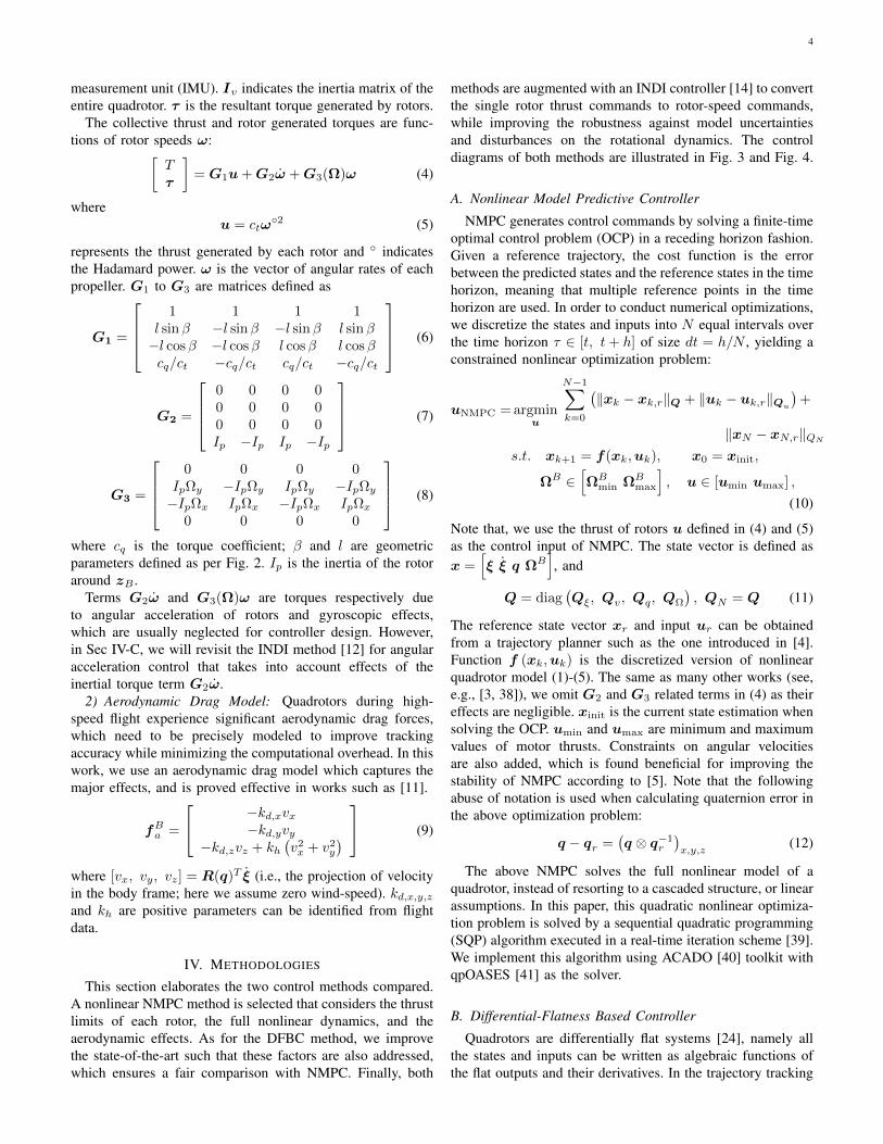
Fig. 2: Coordinate definitions and propeller numbering convention.
at what conditions each approach is preferable to provideinsights and recommendations for future applications.
III. PRELIMINARIES
A. Notations
Throughout the paper, we use subscription r to indicatethe reference variables derived from the reference trajectory.Subscription d indicates the desired value, which is calculatedfrom a higher-level controller. We use bold lowercase lettersto represent vectors and bold uppercase letters for matri-ces; otherwise, they are scalars. Two right-handed coordinateframes are used in this paper: they are the inertial-frame FI :xI ,yI , zI with zI pointing upward opposite to the gravity,and the body-frame FB : xB ,yB , zB with xB pointingforward and zB aligned with the collective thrust direction(see Fig. 2). Vectors with superscription B are expressed inthe body-frame; otherwise they are expressed in the inertial-frame. The rotation from FI to FB is represented by rota-tional matrix R(q) = [xB ,yB , zB ] ∈ SO(3) parameterizedby quaternion q = [qw, qx, qy, qz]
T ∈ S3. Operatordiag(A1, A2, ..., An) denotes a diagonal matrix with scalarsor matrices (A1, A2, ..., An) as diagonal entries.
B. Quadrotor Model
1) Quadrotor Rigid-Body Model: The quadrotor model isestablished using 6-DoF rigid body kinematic and dynamicequations. For translational dynamics, we have
ξ = (TzB + fa)/m+ g, (1)
where ξ denotes the position of the quadrotor center of gravity(CoG); T and m are the collective thrust and total massrespectively; g ∈ is the gravitational vector; fa indicates theexogenous aerodynamic drag force during high-speed flights.
The rotational kinematic and dynamic equations are ex-pressed as
q =1
2q ⊗
[0
ΩB
], (2)
IvΩB
= IvαB = −ΩB × IvΩB + τ , (3)
where ⊗ denotes the quaternion multiplication operator. Ω isthe angular velocity of FB with respect to FI . Its derivative,namely angular acceleration, is denoted by α . Throughoutthe paper, we use its projection on FB , namely ΩB =[Ωx, Ωy, Ωz]
T , since its directly measurable from the inertial
4
measurement unit (IMU). Iv indicates the inertia matrix of theentire quadrotor. τ is the resultant torque generated by rotors.
The collective thrust and rotor generated torques are func-tions of rotor speeds ω:[
Tτ
]= G1u+G2ω +G3(Ω)ω (4)
whereu = ctω
2 (5)
represents the thrust generated by each rotor and indicatesthe Hadamard power. ω is the vector of angular rates of eachpropeller. G1 to G3 are matrices defined as
G1 =
1 1 1 1
l sinβ −l sinβ −l sinβ l sinβ−l cosβ −l cosβ l cosβ l cosβcq/ct −cq/ct cq/ct −cq/ct
(6)
G2 =
0 0 0 00 0 0 00 0 0 0Ip −Ip Ip −Ip
(7)
G3 =
0 0 0 0
IpΩy −IpΩy IpΩy −IpΩy−IpΩx IpΩx −IpΩx IpΩx
0 0 0 0
(8)
where cq is the torque coefficient; β and l are geometricparameters defined as per Fig. 2. Ip is the inertia of the rotoraround zB .
Terms G2ω and G3(Ω)ω are torques respectively dueto angular acceleration of rotors and gyroscopic effects,which are usually neglected for controller design. However,in Sec IV-C, we will revisit the INDI method [12] for angularacceleration control that takes into account effects of theinertial torque term G2ω.
2) Aerodynamic Drag Model: Quadrotors during high-speed flight experience significant aerodynamic drag forces,which need to be precisely modeled to improve trackingaccuracy while minimizing the computational overhead. In thiswork, we use an aerodynamic drag model which captures themajor effects, and is proved effective in works such as [11].
fBa =
−kd,xvx−kd,yvy
−kd,zvz + kh(v2x + v2
y
) (9)
where [vx, vy, vz] = R(q)T ξ (i.e., the projection of velocityin the body frame; here we assume zero wind-speed). kd,x,y,zand kh are positive parameters can be identified from flightdata.
IV. METHODOLOGIES
This section elaborates the two control methods compared.A nonlinear NMPC method is selected that considers the thrustlimits of each rotor, the full nonlinear dynamics, and theaerodynamic effects. As for the DFBC method, we improvethe state-of-the-art such that these factors are also addressed,which ensures a fair comparison with NMPC. Finally, both
methods are augmented with an INDI controller [14] to convertthe single rotor thrust commands to rotor-speed commands,while improving the robustness against model uncertaintiesand disturbances on the rotational dynamics. The controldiagrams of both methods are illustrated in Fig. 3 and Fig. 4.
A. Nonlinear Model Predictive Controller
NMPC generates control commands by solving a finite-timeoptimal control problem (OCP) in a receding horizon fashion.Given a reference trajectory, the cost function is the errorbetween the predicted states and the reference states in the timehorizon, meaning that multiple reference points in the timehorizon are used. In order to conduct numerical optimizations,we discretize the states and inputs into N equal intervals overthe time horizon τ ∈ [t, t+ h] of size dt = h/N , yielding aconstrained nonlinear optimization problem:
uNMPC = argminu
N−1∑k=0
(‖xk − xk,r‖Q + ‖uk − uk,r‖Qu
)+
‖xN − xN,r‖QNs.t. xk+1 = f(xk,uk), x0 = xinit,
ΩB ∈[ΩB
min ΩBmax
], u ∈ [umin umax] ,
(10)
Note that, we use the thrust of rotors u defined in (4) and (5)as the control input of NMPC. The state vector is defined asx =
[ξ ξ q ΩB
], and
Q = diag(Qξ, Qv, Qq, QΩ
), QN = Q (11)
The reference state vector xr and input ur can be obtainedfrom a trajectory planner such as the one introduced in [4].Function f (xk,uk) is the discretized version of nonlinearquadrotor model (1)-(5). The same as many other works (see,e.g., [3, 38]), we omit G2 and G3 related terms in (4) as theireffects are negligible. xinit is the current state estimation whensolving the OCP. umin and umax are minimum and maximumvalues of motor thrusts. Constraints on angular velocitiesare also added, which is found beneficial for improving thestability of NMPC according to [5]. Note that the followingabuse of notation is used when calculating quaternion error inthe above optimization problem:
q − qr =(q ⊗ q−1
r
)x,y,z
(12)
The above NMPC solves the full nonlinear model of aquadrotor, instead of resorting to a cascaded structure, or linearassumptions. In this paper, this quadratic nonlinear optimiza-tion problem is solved by a sequential quadratic programming(SQP) algorithm executed in a real-time iteration scheme [39].We implement this algorithm using ACADO [40] toolkit withqpOASES [41] as the solver.
B. Differential-Flatness Based Controller
Quadrotors are differentially flat systems [24], namely allthe states and inputs can be written as algebraic functions ofthe flat outputs and their derivatives. In the trajectory tracking

5
PD Controller(13) Thrust vector
decomposition(14) - (17)
Tilt-prioritized attitude controller
(25) - (28)
QP-basedControl
allocation(31)
Differentialflatness
(18) - (24)
INDI(32)-(35)
Thrust Estimation(4)(5)
Fig. 3: The control diagram of the differential-flatness based controller, combined with an INDI inner-loop controller.
NonlinearMPC(10)
INDI(32)-(35)
Fig. 4: The control diagram of the model predictive controller with an INDI inner-loop controller.
problem, the flat outputs are selected as positions ξ and head-ing ψ. As its name implies, DFBC leverages the differentialflatness property of a quadrotor to produce reference or desiredstates as feed-forward terms to improve the tracking accuracy.Different from NMPC, the inputs generated by DFBC onlydepend on a single reference point at the current time.
In the following, we introduced the DFBC method improvedfrom a previous work [24], where the original geometric atti-tude controller is replaced by the tilt-prioritized method [30].We also use the quadratic-programming based control allo-cation [13] to address input constraints. These modificationsare beneficial in tracking dynamically infeasible trajectories,as will be discussed in Sec. V-D. Fig. 3 presents an overviewof this method.
1) Desired Attitude and Collective Thrust: First of all, wederive the desired attitude and collective thrust from a PDcontroller and the thrust vector decomposition method. ThePD controller is designed as:
fd/m = Kξ(ξr − ξ) +Kv(ξr − ξ) + ξr + g − fa, (13)
where Kξ and Kv are diagonal gain matrices; fa are aero-dynamic forces calculated from (9).
Then, we can decompose the thrust vector into desired thrustand attitude:
Td = ||fd||, zB,d = fd/Td. (14)
Given reference heading angle ψr, we get an intermediate axisxC,d, by which the desired attitude can be obtained by the
following equations:
xC,d = [cosψr, sinψr, 0]T , (15)
yB,d =zB,d × xC,d||zB,d × xC,d||
, (16)
Rd(qd) = [xB,d, yB,d, zB,d]. (17)
where qd is the desired attitude expressed by the quaternion.2) Reference Angular Velocity and Acceleration: We lever-
age the differential flatness property of a quadrotor to derivethe reference angular velocity and angular accelerations. Usingthem into the attitude control can help in tracking jerk and snap(3rd and 4th order derivative of position ξ), which is foundessential for tracking accuracy [12].
Taking the derivative of both sides of (1) and assuming aconstant external aerodynamic force fa, we have
m...ξ = TzB + TΩ× zB . (18)
Then given reference jerk...ξ r and substitute it for
...ξ in (18),
we gethΩ = Ω× zB =
m
T(...ξ r − TzB), (19)
by which the reference angular velocity can be obtained as
ΩBr =
[−hΩ · yB , hΩ · xB , ψrzW · zB
]T, (20)
where ψr is the reference heading angle.We further take the derivative on both sides of (18) and uses
snap reference....ξ r to replace
....ξ , yielding
hα = Ω× zB
=m
T
....ξ r −
(Ω× (Ω× zB) +
2T
TΩ× zB +
T
TzB
).
(21)

6
Then the desired angular acceleration can be obtained as
αBr =[−hα · yB , hα · xB , ψrzW · zB
]T. (22)
Note that in (20) to (22) we use the current attitudexB , yB , zB, angular velocity Ω, and collective thrust Tinstead of their references. As such, the drone follows thereference jerk
...ξ r and snap
....ξ r even though its attitude,
angular rates, and collective thrust are different from thereference.
While the collective thrust T can be obtained from rotorspeed measurements ω and (4)(5), its derivatives are unable tobe directly measured. For this reason, we approximate themby using reference jerk
...ξ r and snap
....ξ r. Multiplying (dot-
product) both sides of (18) by zB , we have
T = m...ξ r · zB (23)
and its derivative
T = m....ξ r · zB +m(Ω× zB) ·
...ξ r. (24)
3) Tilt-Prioritized Attitude Control: Quadrotors use rotordrag torques to achieve heading control. The control effective-ness of heading is around one order of magnitude lower thanpitch and roll. As a consequence, heading control is prone tocause motor saturations. Fortunately, the thrust orientation ofa quadrotor (namely tilt) is independent of its heading angle.Thus tilt-prioritized control has been proposed in [30] thatregulates the reduced-attitude (pitch and roll) error qe andyaw error qyaw separately as follows
qe = qd ⊗ q−1 = [qe,w, qe,x, qe,y, qe,z]T , (25)
qe,red =1√
q2e,w + q2
e,z
qe,wqe,x − qe,yqe,zqe,wqe,y + qe,xqe,z
0
, (26)
qe,yaw =1√
q2e,w + q2
e,z
[0 0 qe,z]T. (27)
Subsequently, the desired angular acceleration can be obtainedby the following attitude control law:
αBd = kq,redqe,red + kq,yawsgn(qe,w)qe,yaw
+KΩ(ΩB −ΩBr ) +αBr (28)
where kq,red and ke,yaw are positive gains for reduced-attitudeand yaw control respectively. Setting a relatively high kq,redover ke,yaw is helpful in improving position tracking accuracywhile preventing input saturations.
4) Quadratic-Programming-Based Control Allocation: Thecontrol allocation module generates thrust commands of eachindividual rotor from desired collective thrust Td and angularacceleration αBd . The same as NMPC, we also neglect the G2
and G3 terms in (4). Then from (3) and (4), we obtain thedirect-inversion control allocation:
u = G−11
[Td
IvαBd + Iv × IvΩB
], (29)
uDFBC = max (umin, min(u, umax)) (30)
This, however, does not consider input limits and may causeloss-of-control. For instance, an excessive collective thrustcommand can saturate all motors and consequently invalidatethe attitude control.
An effective alternative to address saturations is thequadratic-programming based allocation that solves the fol-lowing optimization problem:
uDFBC = argminu
∥∥∥∥[ TdIvα
Bd + Iv × IvΩB
]−G1u
∥∥∥∥W
s.t. u ∈ [umin umax] ,(31)
where W ∈ R4×4 is a positive-definite diagonal weightmatrix. Each diagonal entry respectively indicates the weighton the thrust, pitch, roll and yaw channels. Generally, settinga relatively high weight on pitch and roll (see Table. I) isadvantageous to prevent quadrotor loss-of-control when motorsaturations are inevitable (e.g., tracking dynamically infeasibletrajectories). If the solution is originally within control bounds,the result is the same as the direct-inversion allocation from(30). As for the implementation details, we solve this quadraticprogramming problem using an Active-Set Method from theqpOASES solver [41].
C. Incremental Nonlinear Dynamic Inversion
After obtaining thrust commands from (10) or (31), one canuse (5) to directly obtain the rotor speed command. However,the above-mentioned controllers do not consider model uncer-tainties, especially those in the rotational dynamics, which arefound detrimental to the overall control performance.
Therefore, we resort to incremental nonlinear dynamicinversion (INDI), a sensor-based controller that uses instan-taneous sensor measurement, instead of a model, to representsystem dynamics, thus is robust against model uncertaintiesand external disturbances. The performance and robustness ofINDI have been demonstrated in previous research (see, e.g.,[14, 12, 15]) with proven stability [42].
We use INDI as the inner-loop controller of both NMPC andDFBC for fair comparisons. The hybridization of INDI andDFBC is similar to a related work [12], except for the attitudecontroller and control allocation introduced in the previoussection. Here, a method is proposed to effectively combineINDI with NMPC to improve its robustness against rotationalmodel uncertainties.
After knowing the single rotor thrust command uDFBC
or uNMPC from (31) and (10) respectively, we can retrievethe desired collective thrust, and desired angular accelerationusing (3) and (4), yielding[
TdIvα
Bd + ΩB × IvΩB
]= G1uDFBC/NMPC. (32)
Note that, for the DFBC method, Td and αB are different fromthose derived from (14) and (28) if the optimal cost of (31)is non-zero. Then from INDI, we can get the desired bodytorque (see (30) and (31) [12] for derivations)
τ d = τ f + Iv
(αBd − Ω
B
f
)(33)

7
where
τ f = G1ω2f + ∆t−1G2 (ωf − ωf,k−1) (34)
is the indirectly measured body torque from rotor speedmeasurements. ΩB
f and ωf are filtered body-rate and rotorspeeds from a second-order filter. Note that we use subscriptk − 1 to indicate the last sampled variable, and ∆t is thesampling interval. G1 and G2 respectively indicate matricesformed by the last three rows of G1 and G2.
Then from (13), we obtain the the following equation tosolve rotor speed command ωc:[
Tdτ d
]= G1ω
2c + ∆t−1G2 (ωc − ωc,k−1) , (35)
with the only unknown ωc which can be solved numerically.Differently from [12], the motor time constant is not neededin (35).
The INDI inner-loop controller converts the original thrustinputs from the high-level controller to rotor speed commands.Because this conversion is through algebraic equations, systemdelay typically seen in the cascaded control structures can beeffectively circumvented. The advantage of INDI over classicalPID inner-loop controller will be demonstrated in Sec. VI.
V. SIMULATION EXPERIMENTS
In a set of controlled experiments in simulation, we examineDFBC and NMPC to address the following research questions:(i) Given the computational budget and a well-identifiedmodel, which control approach achieves better tracking perfor-mance? (ii) How do these two approaches perform in trackingdynamically infeasible trajectories, which inevitably lead toactuator saturation? (iii) How do these two approaches performin simulated practical situations with a model mismatch,external disturbances, state estimation latency? Note that inthis section, both methods are tested with the augmentation ofthe INDI inner-loop controller. In this section, we use NMPCand DFBC to represent those with INDI and an aerodynamicdrag model for readability.
A. Simulation Setup
The simulator uses a 4th-order Runge-Kutta integrator topropagate quadrotor dynamic equations (1)-(4) at 500 Hz.Rotor speed commands generated by the controllers passthrough a low-pass filter with a 30 ms time constant to simulatethe motor dynamics. By assuming the controller knows aperfect aerodynamics model, we include the aerodynamic dragmodel (9) in the simulator. The parameters of the simulateddrone are given in Table II.
TABLE I: Controller gains and parameters
NMPC DFBC
Qξ diag(200, 200, 500) Kξ diag(10, 10, 10)Qv diag(1, 1, 1) Kv diag(6, 6, 6)Qq diag(5, 5, 200) kqx, kqy, kqz 150, 150, 3QΩ diag(1, 1, 1) KΩ diag(20, 20, 8)R diag(6, 6, 6, 6) W diag(0.001, 10, 10, 0.1)dt 50 msN 20
TABLE II: Quadrotor Configurations
Parameter(s) Value(s)
m [kg] 0.75l [m] 0.14β [deg] 56Iv [gm2] diag(2.5, 2.1, 4.3)
(umin, umax) [N] (0, 8.5)cq [Nm2] 2.37e−8
ct [N2] 1.51e−6(kd,x, kd,y , kd,z
)[kg/s] (0.26, 0.28, 0.42)
kh [kg/m] 0.01
B. Reference Trajectories
Multiple elliptical reference trajectories on both horizontaland vertical planes are generated for testing the trackingperformance. Specifically, the horizontal reference trajectoriesare expressed as:
ξr(t) = [rmax sin(kt), rmin cos(kt), 5]T
; (36)
and the vertical reference trajectories are
ξr(t) = [rmax sin(kt), 0, 5 + rmin cos(kt)]T (37)
where
rmax = V 2max/amax, k = amax/Vmax, rmin = rmax/n (38)
The heading angle of each horizontal reference trajectory isselected to always point at the center of the ellipse; for verticaltrajectories, the reference heading angles are kept constant.
Specifically, 144 reference trajectories aregenerated by combining parameters amax ∈10, 20, 30, 40, 50, 60 m/s2, Vmax ∈5, 10, 15, 20 m/s, n ∈ 1, 2, 5. Moreover, theyare classified into 78 feasible and 68 infeasible trajectories. Atrajectory is feasible if none of the commanded rotor thrustsexceeds its limit; otherwise, it is classified as dynamicallyinfeasible.
1) Evaluation Criteria: In the following comparisons, weuse the root mean square error (RMSE) of position andheading as the precision metric of a method. The crash rateis another criterion to show the robustness of a method. Acertain flight is defined as Crashed if its position ξ violatesthe following spatial constraint at an arbitrary instant:
infξr(t) − b ≤ ξ ≤ supξr(t)+ b. (39)
We select b = [5, 5, 5]T meters in this study.
C. Tracking Dynamically Feasible Trajectories
First of all, we compare the performance of NMPC andDFBC in tracking 78 feasible trajectories. We perform the testin an ideal condition with perfect model knowledge and stateestimates. Since only feasible trajectories are tracked, there isno saturation of single rotor thrusts and both methods succeedin tracking all trajectories without a single crash.
In this set of tests, we fine-tune the parameters of bothmethods (listed in Table. I) to achieve their best performance.Fig. 5 compares the boxplots of NMPC and DFBC when track-ing trajectories with different reference maximum velocities.Both methods have similarly position RMSE in these flights.

8
5 10 15 20
Maximum velocity [m/s]
0
0.05
0.1
0.15
Pos
ition
RM
SE
[m]
NMPCDFBC
(a)
5 10 15 20
Maximum velocity [m/s]
0
5
10
15
20
Hea
ding
RM
SE
[deg
]
NMPCDFBC
(b)Fig. 5: Boxplot of tracking error (RMSE) in tracking differentdynamically feasible trajectories categorized by maximum velocities.
10 20 30 40 50 60Maximum acceleration [m/s2]
0
1
2
3
4
Posi
tion
RM
SE [m
]
NMPCDFBC
(a)
10 20 30 40 50 60Maximum acceleration [m/s2]
0
20
40
60
80
Hea
ding
RM
SE [d
eg] NMPC
DFBC
(b)Fig. 6: Boxplot of tracking error (RMSE) in tracking different dynam-ically infeasible trajectories categorized by maximum accelerations.Crashed flights are removed from these analyses (see Fig. 7 for thecrash rate).
Interestingly, the position error grows as the reference velocityincreases, even though a perfect aerodynamic model is given.As for the heading tracking, NMPC has an average headingRMSE of 1.8 deg, which is better than 3.6 deg of DFBC.
D. Tracking Dynamically Infeasible Trajectories
In many time-critical applications, such as autonomousdrone racing, rotors need to reach their full thrust limits tofully exploit the agility of the platform. Designing such anagile time-optimal trajectory requires a perfect model that
10 20 30 40 50 60Maximum acceleration [m/s2]
0
20
40
60
80
100
Cra
she
rate
[%]
NMPCDFBC
DFBC w/o QP based allocationDFBC w/o tilt-prioritization
Fig. 7: Crash rates of NMPC, DFBC, and DFBC with different setups:DFBC without quadratic-programming based allocation, DFBC with-out tilt-prioritized attitude controller but using the geometric attitudecontroller.
captures real thrust limits and aerodynamic effects in high-speed flights. Otherwise, the generated trajectory may exceedthe quadrotor capability and becomes dynamically infeasibleto track without error. Since such an accurate model is usuallyunattainable, studying the performance when tracking theseinfeasible trajectories is necessary.
1) Tracking Accuracy: Fig. 6 shows the box plot of positionand heading RMSE of NMPC and DFBC in tracking thepreviously generated 68 infeasible trajectories. Crashed flightsare excluded from this plot (see Fig. 7 for the crash rate). Wefind that the DFBC method shows smaller position RMSE intracking trajectories with lower acceleration. However, as thereference acceleration grows, NMPC significantly outperformsDFBC. In general, NMPC outperforms DFBC by 57% onposition tracking (0.38 m vs. 0.90 m). As for the headingtracking, NMPC has significantly smaller (64%) RMSE thanthe DFBC method (10.1 deg vs. 28.2 deg). The advantageof NMPC over DFBC becomes particularly relevant if thereference acceleration exceeds the maximum thrust (∼ 5g) ofthe tested quadrotor (The gray area in Fig. 6).
2) Crash Rates: Fig. 7 compares the crash rates of DFBCand NMPC in tracking all the infeasible trajectories. NMPC(solid-blue) outperforms DFBC (red-dash-dot), especially intracking trajectories with high reference accelerations. In fact,only 18% of flights using NMPC crash and this only happenswhen the reference trajectory requires an acceleration of 6 g,whereas the thrust-to-weight ratio of the simulated platform isonly 4.5.
Here, we also demonstrate contributions of the tilt-prioritized attitude controller and the quadratic-programmingbased allocation presented in Sec. IV. We replace them respec-tively with the conventional geometric attitude controller [23]and the direct-inversion allocation (30). The resultant crashrates are shown in Fig. 7 as well. It is obvious that the DFBCmethod tested in this study shows a significantly lower crashrate in tracking infeasible trajectories.
E. Robustness Study
While previous simulations are carried out in an idealcondition, this section studies the robustness of NMPC andDFBC methods in the following non-ideal conditions:• Model mismatch, including the center of gravity bias,
mass mismatch, thrust coefficient model mismatch, anderror of aerodynamic drag model.

9
TABLE III: Tracking performance comparisons in different types ofnon-ideal conditions commonly seen in practice.
Position RMSE[m]
Heading RMSE[deg]
Crash Rate[%]
NMPC DFBC NMPC DFBC NMPC DFBC
Basline 0.062 0.062 1.82 3.63 0 0
+50% Drag 0.160 0.154 1.87 5.56 0 0+100% Drag 0.259 0.249 1.98 6.12 0 0
-30% Mass 0.293 0.433 2.05 6.72 0 0+30% Mass 0.759 0.628 11.15 5.77 10.3 0
10% CoG bias 0.061 0.077 1.87 4.02 0 015% CoG bias 0.063 0.304 1.82 7.26 0 3.8
-30% Ct 1.059 0.897 14.63 6.62 12.8 0+30% Ct 0.221 0.329 1.91 3.88 0 0
5N Ext. force 0.229 0.235 3.88 10.55 0 010N Ext. force 0.637 0.553 9.30 16.75 3.8 1.315N Ext. force 1.825 1.198 30.05 25.3 26.9 7.7
0.1Nm Ext. moment 0.064 0.064 2.00 4.67 0 00.2Nm Ext. moment 0.069 0.086 2.54 8.27 0 00.3Nm Ext. moment 0.216 0.501 6.44 18.62 2.6 7.7
10ms Latency 0.061 0.064 1.82 3.08 0 030ms Latency 0.116 0.266 4.66 9.82 0 3.850ms Latency 2.23 0.575 45.03 39.72 37.2 6.4
• External disturbances. In details, we simulate constantexternal forces along xI , or external torques along bothxB and yB . These disturbances last for 5 seconds.
• Pose and velocity estimation latency. This aims at study-ing the effect of latency from such as signal transmission,state estimation algorithms, and sensors. As angular ratesare measured directly by IMU with negligible latency, weonly study the latency on pose and velocity estimates.
Note that, both NMPC and DFBC have been augmented withthe INDI inner-loop controller to compensate for the modelmismatch and external disturbances on the rotational dynam-ics. These robustness studies are conducted using only thefeasible trajectories since NMPC already shows its advantageover DFBC in tracking infeasible trajectories. We set theposition RMSE as 5.0 m and heading RMSE as 90 deg forthose crashed flights.
The comparison results are presented in Table. III. We havethe following observations.
NMPC shows higher robustness than DFBC against modeluncertainties and disturbances on rotational dynamics dueto CoG bias or external moments. Interestingly, such anadvantage appears even though both methods are augmentedby an INDI inner-loop controller.
Unlike the rotational dynamics, NMPC shows a higher crashrate while experiencing model uncertainties and disturbancesacting on the translational dynamics. For example, when thereal mass is 30% higher, both controllers generate fewer thruststhan required to track the trajectory, resulting in a constantposition tracking error. With this tracking error, NMPC failsto converge in over 10% of flights and crashes the drone. Thesame reason also explains the significantly higher crash rate ofNMPC in the presence of large external disturbances. Fig. 8shows an example where NMPC failed in converging and crashthe drone after experiencing a 10 N external force disturbance.
The two methods also perform differently in the presence
0 5 10 15 20Time [s]
0
20
40
60
80
Pos
ition
RM
SE
[m]
NMPCDFBC10N external force
Fig. 8: Position tracking error for a loop trajectory (Vmax = 15m/s,amax = 40m/s2, n = 1). Grey area indicates the period with 10 Nlateral disturbances acting on the drone. NMPC failed to converge andcrashed the drone, while the DFBC method succeeds in recovery thedrone after the external disturbance disappeared.
0 10 20 30 40 50Latency [ms]
0
0.5
1
1.5
2
2.5
3
posi
tion
RM
SE
[m]
NMPCDFBC
high-gains
low-gains
Fig. 9: Position RMSE of NMPC and DFBC in the presence ofdifferent amounts of estimation latency, with different sets of controlgains. Results using gains of previous studies are shown in dash-dotlines. NMPC shows higher sensitivity to the gain selections whenestimation latency appears.
of system latency. While NMPC slightly outperforms DFBCwhen the system latency is lower than 30 ms, as the latencygrows, NMPC shows a much higher crash rate (37.2%) thanDFBC (6.4%). As Fig. 9 shows, we repeat the tests under30 ms and 50 ms latency with a high-gain setup and a low-gain setup. In both setups, these gains are tuned such thatboth controllers have identical average position RMSE in theideal condition. As is expected, reducing gains will alleviatethe effect of estimation latency. Interestingly, we observe thatNMPC is more sensitive to the gain selections when systemlatency is larger than 30 ms.
VI. REAL-WORLD EXPERIMENTS
We conduct the experiments on a quadrotor in an instru-mented tracking arena. A set of aggressive trajectories areexecuted to compare the closed-loop tracking performance ofNMPC and DFBC in the presence of joint effects such asmodel mismatch, state estimation error, and system latency.The real-world experiments also highlight the contributions ofthe INDI low-level controller, the aerodynamic force model,to both NMPC and DFBC methods.
A. Experimental Setup
The real-flight experiment is performed in an indoor arenaequipped with a motion capture system (VICON), with a 30× 30 × 8 m3 tracking volume, as is shown in Fig. 1. Theinertial and geometric parameters of the quadrotor are listedin Table II, which are the same for the simulation study in

10
TABLE IV: Tracking performance of different methods in real-world experiments
References Position Tracking RMSE [m] Heading Tracking RMSE [deg]
Type Vm
ax
[m/s
]
am
ax
[m/s
2]
NM
PC+P
ID[4
]
NM
PC
NM
PC+I
ND
I
NM
PC+I
ND
I(w
/odr
agm
odel
)
DFB
C
DFB
C+I
ND
I
DFB
C+I
ND
I(w
/odr
agm
odel
)
NM
PC+P
ID[4
]
NM
PC
NM
PC+I
ND
I
NM
PC+
IND
I(w
/odr
agm
odel
)
DFB
C
DFB
C+
IND
I
DFB
C+
IND
I(w
/odr
agm
odel
)
Loop A 10.2 20.7 0.280 0.548 0.068 0.215 0.897 0.073 0.242 6.801 11.274 8.450 8.972 73.842 4.411 9.395Loop B 13.4 35.9 0.369 0.930 0.117 0.261 - 0.125 0.252 11.618 22.193 9.714 10.478 - 10.496 11.489Slant Loop A 8.2 12.6 0.241 0.458 0.077 0.156 0.535 0.109 0.163 6.951 19.795 5.987 6.870 17.755 7.521 8.032Slant Loop B 12.9 30.8 0.447 0.777 0.116 0.217 - 0.138 0.305 7.729 18.382 8.282 8.816 - 9.171 10.047Vertical Loop A 7.7 14.6 0.197 0.206 0.069 0.172 0.181 0.082 0.127 1.558 5.131 1.108 1.274 30.901 1.151 1.530Vertical Loop B 11.5 32.9 0.482 0.350 0.126 0.314 - 0.177 0.196 19.000 6.019 2.415 1.900 - 15.495 8.632Oscillate A 10.9 20.7 0.327 0.212 0.058 0.259 0.310 0.164 0.210 1.641 7.369 2.029 1.960 50.210 3.977 1.911Oscillate B 14.0 36.5 0.375 0.290 0.125 0.377 - 0.129 0.294 2.708 9.228 2.386 2.902 - 2.763 3.821Hairpin A 7.7 14.6 0.185 0.352 0.024 0.146 0.350 0.049 0.124 4.733 7.100 3.745 4.255 38.980 5.913 5.873Hairpin B 11.5 32.9 0.390 0.479 0.099 0.274 1.797 0.117 0.166 7.965 15.748 7.343 8.017 68.139 10.163 8.004Lemniscate A 9.5 13.6 0.225 0.324 0.056 0.184 0.423 0.068 0.216 3.576 9.074 3.689 4.109 37.235 2.605 2.243Lemniscate B 14.2 36.0 0.314 0.564 0.130 0.290 - 0.128 0.287 7.335 15.952 6.280 6.659 - 4.986 5.403Split-S 14.2 25.5 0.292 0.352 0.096 0.262 - 0.087 0.239 9.411 13.253 6.409 5.259 - 17.888 18.929Racing Track A 11.9 22.1 0.280 0.424 0.108 0.212 0.552 0.102 0.240 6.806 10.434 6.566 7.706 37.731 4.336 5.390Racing Track B 16.8 28.5 0.369 0.546 0.130 0.320 3.797 0.152 0.359 11.930 14.672 9.318 8.805 57.810 8.249 7.719Racing Track C 19.4 37.3 0.712 0.758 0.238 0.329 - 0.259 0.480 11.235 19.936 11.754 9.876 - 14.695 15.498
Avgerage RMSE 0.343 0.473 0.102 0.249 0.982 0.122 0.244 7.562 12.848 5.967 6.116 45.845 7.739 7.745
Fig. 10: Tested trajectories in real-world experiments. From top-left to bottom right, they are: Loop, Oscillate, Hairpin, Slant-loop, Vertical-loop, Split-S, Lemniscate, Racing-trajectory.
TABLE V: Performance in tracking three dynamically infeasibletrajectories in real-world experiments. Position and heading RMSEcomparisons between NMPC and DFBC with INDI inner-loop.
Reference Vmax
[m]amax
[m/s2]
Position RMSE [m] Heading RMSE [deg]
NMPC+INDI
DFBC+INDI
NMPC+INDI
DFBC+INDI
Vertical Loop C 12.1 48.5 0.318 0.919 2.469 25.608Loop C 15.7 49.3 0.762 1.829 13.439 25.876Lemniscate C 19.0 54.5 0.570 1.237 11.680 53.262
Avgerage RMSE 0.550 1.328 9.196 34.915
Sec. V. The control algorithms run on an NVIDIA Jetson TX2embedded computer. While DFBC runs at 300 Hz, NMPConly runs at 100 Hz due to its computational complexity.The INDI inner-loop also runs at 300 Hz no matter whichcontroller is selected. The onboard computer sends rotor speedcommands of individual rotors to a low-level RadixFC board.The latter runs a customized firmware at 500 Hz to performclosed-loop rotor speed control, and sends rotor speed andIMU measurements to the onboard computer. The full-stateestimates are obtained by an extended Kalman filter runningonboard fusing VICON and IMU measurements.
Experiments are conducted in tracking different reference
trajectories, ranging from simple loop trajectories to FPVdrone racing tracks (see Table. IV). Trajectories with the same3D shape but different velocities and accelerations are alsotested. The 3D paths of these trajectories are illustrated inFig. 10.
We evaluated NMPC and DFBC, with and without the INDIinner-loop controller. NMPC with a PID low-level controller isalso tested for comparison, implemented to track time-optimaltrajectory in [4]. In the following, these methods consideraerodynamic drag models by default, unless further mentioned.The position tracking RMSE and heading tracking RMSE arelisted in Table. IV and Table. V.
B. Contribution of the INDI and Drag Model
Table VI compares the average RMSE of both methodsand shows the effect of the INDI inner-loop controller, andthe effect of the aerodynamic drag model. For NMPC andDFBC, neglecting aerodynamic drag would increase positiontracking error by 144% percent and 122%, respectively. Incontrast to the aerodynamic drag model, removing the INDIlow-level controller influences more on the tracking accuracy.For NMPC, we see more than 364% and 115% increase in

11
− 5.0 − 2.5 0.0 2.5 5.0 7.5 10.0 12.5x [m]
− 6
− 4
− 2
0
2
4
6
8
y[m
] 0.0
0.5
1.0
1.5
Pos
ition
Err
or[m
]
0 1 2 3 4 5 6
5
10
15
20
Flig
ht S
peed
[m/s
]
Time [s]
Reference NMPC+PID NMPC+INDI DFBC+INDI
Fig. 11: Tracking performance of the Race Track C with a maximum speed up to 20 m/s. NMPC and DFBC with INDI inner-loop showsimilar tracking performance. Both outperform the state-of-the-art NMPC with a PID inner-loop controller [4]
position and heading RMSE if INDI is not used. For DFBC,removing INDI leads to a more severe consequence: morethan 705% and 492% of position and heading RMSE increase.In fact, DFBC without INDI cannot successfully track someof these trajectories without crashing the drone. These resultsindicate that, an adaptive/robust inner-loop controller plays amore important role than the drag model in accurately trackingaggressive trajectories.
We also make comparisons against the control method usedin [4], which uses PID as the inner-loop controller of NMPC.This comparison is made in tracking a time-optimal trajectorygenerated off-line using the algorithm proposed in [4]. In thistask, the quadrotor needs to fly through multiple gates in apredefined order. Fig. 11 demonstrates the tracking results,including the 3D path and the position error. Clearly, bothNMPC and DFBC augmented by INDI significantly outper-form this NMPC with PID inner-loop controller. Comparativeresults on other reference trajectories can be found in Table IV.On average, the proposed NMPC with the INDI approachshows a position RMSE of 0.102 m, which is 70% lower thanthe position RMSE of NMPC with PID low-level controller(0.343 m).
TABLE VI: Position and heading tracking RMSE of NMPC andDFBC methods. Adding INDI as the inner-loop improves the per-formance significantly for both methods.
Position RMSE [m] Heading RMSE [deg]
NMPC+INDI 0.102 (↑ 0%) 5.967 (↑ 0%)NMPC+INDI (w/o drag model) 0.249 (↑ 144%) 6.116 (↑ 3%)NMPC 0.473 (↑ 364%) 12.848 (↑ 115%)
DFBC+INDI 0.122 (↑ 0%) 7.739 (↑ 0%)DFBC+INDI (w/o drag model) 0.271 (↑ 122%) 7.745 (↑ 0.07%)DFBC 0.982 (↑ 705%) 45.845 (↑ 492%)
C. Tracking Dynamically Infeasible Trajectories
In these real-world experiments, we also track three dynam-ically infeasible trajectories that exceed the maximum thrust ofthe tested quadrotor. Comparative results of NMPC and DFBC
-6 -4 -2 0 2 4 6
x [m]
-5
-4
-3
-2
-1
0
1
2
3
4
5
y [m
]
Reference DFBC+INDI NMPC+INDI
-6 -4 -2 0 2 4 6
x [m]
0.5
1
1.5
2
z [m
]
Fig. 12: Top and side view of the trajectory tracking a dynamically in-feasible trajectory (black-dash) using NMPC (blue-solid) and DFBCmethod (red-dash-dot).
are given in Table V. Clearly, NMPC shows significantlyhigher tracking accuracy than DFBC when tracking thesedynamically infeasible trajectories, which is inconsistent withthe simulation results in Sec. V.
Fig. 12 presents the 3D path tracking the Loop C referencetrajectory. Tracking such a reference loop trajectory requires ahigher collective thrust than the maximum thrust of the testedquadrotor. Hence the quadrotor cannot follow the referencetrajectory and both control methods make the quadrotor takethe shortcut to fly inside the reference trajectory. While DFBC

12
Fig. 13: Processing time to generate each control command of NMPCand DFBC methods.
results in a chaotic trajectory, NMPC makes the drone fly amuch more regular loop trajectory with a smaller radius thanthe reference, thus requiring less collective thrust. The differ-ence on the side-view is more distinctive: NMPC has muchhigher altitude tracking accuracy than the DFBC method.
D. Computational Time
Fig. 13 compares the average computational time of gen-erating each control commands of NMPC and DFBC, withINDI as the inner-loop controller. Each data point in the boxplot represents the average computing time of a single flight.As is expected, NMPC requires significantly longer time togenerate a single control command (2.7 ms) compared withDFBC (0.020 ms). Be that as it may, both methods can runonboard at sufficiently high frequency (≥100 Hz) to achieveaccurate tracking of agile trajectories.
VII. DISCUSSION
According to the simulation and real-world flight results, weconclude that both NMPC and DFBC, with an INDI inner-loopcontroller, can track highly aggressive trajectories with similaraccuracy as long as the reference trajectories are dynamicallyfeasible.
The advantage of NMPC appears when tracking dynam-ically infeasible trajectories that violate the rotor thrustconstraints. Even though DFBC also uses the constrained-quadratic programming for control allocation, it only considersa single reference point; thus, the actions taken are too short-sighted to avoid future violations of these constraints. Bycontrast, NMPC tracks the infeasible trajectory using futurepredictions, including multiple reference points that minimizethe tracking error and respect single rotor constraints. Suchdifference helps NMPC outperform DFBC by 57% and 64%on position and heading accuracy, respectively, if the referencetrajectories are dynamically infeasible.
NMPC also demonstrates higher robustness against therotational model mismatch. In real-world experiments, wealso performed tests without INDI low-level controller forcomparisons. As such, both methods suffered from modeluncertainties on the rotational dynamics. In this condition,NMPC was still able to track all the trajectories, whereas
DFBC experienced several crashes and had much highertracking RMSE against NMPC.
However, NMPC also has limitations. For example, thebiggest disadvantage of NMPC is that it requires significantlyhigher computational resources. On our tested hardware, theaverage solving time of the nonlinear NMPC is around 2.7ms, while DFBC needs only 0.020 ms, which is around 100times faster. This renders it impractical to run NMPC on someminiature aerial vehicles with a limited computational budget,such as Crazyflie [43] . By contrast, we can deploy DFBC onlight-weighted drones with low-end processors and conductagile flights at speeds over 20 m/s, as long as the platform hasenough thrust-to-weight ratio.
Another disadvantage of NMPC is that it potentially suffersfrom numerical convergence issues. Unlike DFBC, which hasproof of stability or convergence of each sub-module, thenonlinear NMPC used in this comparison relies on the nu-merical convergence of the nonlinear optimization algorithm.Unfortunately, rigorous proof of its convergence is still an openquestion. In fact, nonlinear NMPC tends to fail in convergingwhen the current position is too far from the reference, eithercaused by large external force disturbances or an error inthe thrust-to-weight ratio model. For example, our robustnessstudy shows a 10% higher crash rate of NMPC than DFBCwhen the real mass is 30% higher than the model. In addition,we also observe that NMPC is more prone to fail in convergingthan DFBC in the presence of large system latency.
In summary, NMPC is not superior to DFBC in all sce-narios. If the reference trajectories are dynamically feasible,DFBC can achieve similar tracking performance while con-suming only 1 percent of the control resource that NMPCrequires. However, it is difficult to justify the feasibility ofa trajectory near the physical limitations of the platform be-cause of the model uncertainties such as aerodynamic effects.Hence, NMPC excels at exploiting the full capability of anautonomous drone in a safer and more efficient manner, dueto its advantage in handling the infeasibility of referencetrajectories.
VIII. CONCLUSION
This work systematically compares NMPC and DFBC, twostate-of-the-art quadrotor controllers for tracking agile trajec-tories. Simulation and real-world experiments are extensivelyperformed to evaluate the performance of both methods interms of accuracy, robustness, and computational efficiency.We report the advantages and disadvantages of both methodsaccording to the results. This work also evaluates the effectof INDI inner-loop control on both methods. Real-world flightresults at up to 20 m/s demonstrate the necessity of applyingan INDI inner-loop on both NMPC and DFBC approaches.The effect of the high-speed aerodynamic drag model is alsoevaluated, which is found less influential compared to theinner-loop controller.
ACKNOWLEDGMENT
We thank Thomas Langle and Leonard Bauersfeld for theirhelp in experiments and photo rendering. We also appreciate

13
the valuable feedback from Yunlong Song, Antonio Loquercio,and Drew Hanover.
REFERENCES
[1] G. Loianno and D. Scaramuzza, “Special issue on fu-ture challenges and opportunities in vision-based dronenavigation,” 2020.
[2] S. Rajendran and S. Srinivas, “Air taxi service for urbanmobility: A critical review of recent developments, futurechallenges, and opportunities,” Transportation ResearchPart E: Logistics and Transportation Review, vol. 143,p. 102090, Nov 2020. arXiv: 2103.01768.
[3] D. Bicego, J. Mazzetto, R. Carli, M. Farina, andA. Franchi, “Nonlinear model predictive control withenhanced actuator model for multi-rotor aerial vehicleswith generic designs,” Journal of Intelligent & RoboticSystems, vol. 100, no. 3, pp. 1213–1247, 2020.
[4] P. Foehn, A. Romero, and D. Scaramuzza, “Time-optimal planning for quadrotor waypoint flight,” ScienceRobotics, vol. 6, no. 56, 2021.
[5] G. Torrente, E. Kaufmann, P. Fohn, and D. Scaramuzza,“Data-driven mpc for quadrotors,” IEEE Robotics andAutomation Letters, vol. 6, no. 2, pp. 3769–3776, 2021.
[6] M. Kamel, K. Alexis, M. Achtelik, and R. Siegwart,“Fast nonlinear model predictive control for multicopterattitude tracking on so (3),” in 2015 IEEE Conferenceon Control Applications (CCA), pp. 1160–1166, IEEE,2015.
[7] M. Kamel, T. Stastny, K. Alexis, and R. Siegwart,“Model predictive control for trajectory tracking of un-manned aerial vehicles using robot operating system,” inRobot operating system (ROS), pp. 3–39, Springer, 2017.
[8] A. Murilo and R. V. Lopes, “Unified nmpc frameworkfor attitude and position control for a vtol uav,” Proceed-ings of the Institution of Mechanical Engineers, Part I:Journal of Systems and Control Engineering, vol. 233,no. 7, pp. 889–903, 2019.
[9] E. Small, P. Sopasakis, E. Fresk, P. Patrinos, and G. Niko-lakopoulos, “Aerial navigation in obstructed environ-ments with embedded nonlinear model predictive con-trol,” in 2019 18th European Control Conference (ECC),pp. 3556–3563, IEEE, 2019.
[10] H. Nguyen, M. Kamel, K. Alexis, and R. Siegwart,“Model predictive control for micro aerial vehicles: Asurvey,” arXiv preprint arXiv:2011.11104, 2020.
[11] M. Faessler, A. Franchi, and D. Scaramuzza, “Differen-tial flatness of quadrotor dynamics subject to rotor dragfor accurate tracking of high-speed trajectories,” IEEERobotics and Automation Letters, vol. 3, no. 2, pp. 620–626, 2017.
[12] E. Tal and S. Karaman, “Accurate tracking of aggres-sive quadrotor trajectories using incremental nonlineardynamic inversion and differential flatness,” IEEE Trans-actions on Control Systems Technology, 2020.
[13] T. A. Johansen and T. I. Fossen, “Control allocation—asurvey,” Automatica, vol. 49, no. 5, pp. 1087–1103, 2013.
[14] E. J. Smeur, Q. Chu, and G. C. de Croon, “Adaptiveincremental nonlinear dynamic inversion for attitude con-
trol of micro air vehicles,” Journal of Guidance, Control,and Dynamics, vol. 39, no. 3, pp. 450–461, 2016.
[15] S. Sun, X. Wang, Q. Chu, and C. de Visser, “Incrementalnonlinear fault-tolerant control of a quadrotor with com-plete loss of two opposing rotors,” IEEE Transactions onRobotics, 2020.
[16] T. P. Nascimento and M. Saska, “Position and attitudecontrol of multi-rotor aerial vehicles: A survey,” AnnualReviews in Control, vol. 48, pp. 129–146, 2019.
[17] H. Lee and H. J. Kim, “Trajectory tracking control ofmultirotors from modelling to experiments: A survey,”International Journal of Control, Automation and Sys-tems, vol. 15, no. 1, pp. 281–292, 2017.
[18] S. Khatoon, D. Gupta, and L. Das, “Pid & lqr controlfor a quadrotor: Modeling and simulation,” in 2014international conference on advances in computing, com-munications and informatics (ICACCI), pp. 796–802,IEEE, 2014.
[19] W. Dong, G.-Y. Gu, X. Zhu, and H. Ding, “Modeling andcontrol of a quadrotor uav with aerodynamic concepts,”in Proceedings of World Academy of Science, Engineer-ing and Technology, no. 77, p. 437, World Academy ofScience, Engineering and Technology (WASET), 2013.
[20] H. Voos, “Nonlinear control of a quadrotor micro-uav us-ing feedback-linearization,” in 2009 IEEE InternationalConference on Mechatronics, pp. 1–6, IEEE, 2009.
[21] T. Madani and A. Benallegue, “Backstepping control fora quadrotor helicopter,” in 2006 IEEE/RSJ InternationalConference on Intelligent Robots and Systems, pp. 3255–3260, IEEE, 2006.
[22] E. Fresk and G. Nikolakopoulos, “Full quaternion basedattitude control for a quadrotor,” in 2013 Europeancontrol conference (ECC), pp. 3864–3869, IEEE, 2013.
[23] T. Lee, M. Leok, and N. H. McClamroch, “Geomet-ric tracking control of a quadrotor uav on se (3),” in49th IEEE conference on decision and control (CDC),pp. 5420–5425, IEEE, 2010.
[24] D. Mellinger and V. Kumar, “Minimum snap trajectorygeneration and control for quadrotors,” in 2011 IEEEinternational conference on robotics and automation,pp. 2520–2525, IEEE, 2011.
[25] R. Mahony, V. Kumar, and P. Corke, “Multirotor aerialvehicles: Modeling, estimation, and control of quadro-tor,” IEEE Robotics and Automation magazine, vol. 19,no. 3, pp. 20–32, 2012.
[26] S. Sun, C. C. de Visser, and Q. Chu, “Quadrotor gray-boxmodel identification from high-speed flight data,” Journalof Aircraft, vol. 56, no. 2, pp. 645–661, 2019.
[27] H. Huang, G. M. Hoffmann, S. L. Waslander, andC. J. Tomlin, “Aerodynamics and control of autonomousquadrotor helicopters in aggressive maneuvering,” in2009 IEEE international conference on robotics andautomation, pp. 3277–3282, IEEE, 2009.
[28] M. Faessler, D. Falanga, and D. Scaramuzza, “Thrustmixing, saturation, and body-rate control for accurateaggressive quadrotor flight,” IEEE Robotics and Automa-tion Letters, vol. 2, no. 2, pp. 476–482, 2016.
[29] E. Smeur, D. Hoppener, and C. De Wagter, “Prioritized

14
control allocation for quadrotors subject to saturation,”in International Micro Air Vehicle Conference and FlightCompetition, no. September, pp. 37–43, 2017.
[30] D. Brescianini and R. D’Andrea, “Tilt-prioritized quadro-copter attitude control,” IEEE Transactions on ControlSystems Technology, vol. 28, no. 2, pp. 376–387, 2018.
[31] H. Zaki, M. Unel, and Y. Yildiz, “Trajectory control of aquadrotor using a control allocation approach,” in 2017International Conference on Unmanned Aircraft Systems(ICUAS), pp. 533–539, IEEE, 2017.
[32] M. Kamel, M. Burri, and R. Siegwart, “Linear vsnonlinear mpc for trajectory tracking applied to rotarywing micro aerial vehicles,” IFAC-PapersOnLine, vol. 50,no. 1, pp. 3463–3469, 2017.
[33] M. Bangura and R. Mahony, “Real-time model predic-tive control for quadrotors,” IFAC Proceedings Volumes,vol. 47, no. 3, pp. 11773–11780, 2014.
[34] K. Alexis, G. Nikolakopoulos, and A. Tzes, “On tra-jectory tracking model predictive control of an un-manned quadrotor helicopter subject to aerodynamicdisturbances,” Asian Journal of Control, vol. 16, no. 1,pp. 209–224, 2014.
[35] B. Houska, H. J. Ferreau, and M. Diehl, “Acadotoolkit—an open-source framework for automatic controland dynamic optimization,” Optimal Control Applica-tions and Methods, vol. 32, no. 3, pp. 298–312, 2011.
[36] Y. Chen, M. Bruschetta, E. Picotti, and A. Beghi,“Matmpc-a matlab based toolbox for real-time nonlin-ear model predictive control,” in 2019 18th EuropeanControl Conference (ECC), pp. 3365–3370, IEEE, 2019.
[37] J. A. Andersson, J. Gillis, G. Horn, J. B. Rawlings, andM. Diehl, “Casadi: a software framework for nonlinearoptimization and optimal control,” Mathematical Pro-gramming Computation, vol. 11, no. 1, pp. 1–36, 2019.
[38] M. Jacquet and A. Franchi, “Motor and perceptionconstrained nmpc for torque-controlled generic aerialvehicles,” IEEE Robotics and Automation Letters, 2020.
[39] M. Diehl, H. G. Bock, H. Diedam, and P.-B. Wieber,“Fast direct multiple shooting algorithms for optimalrobot control,” in Fast motions in biomechanics androbotics, pp. 65–93, Springer, 2006.
[40] R. Verschueren, G. Frison, D. Kouzoupis, N. van Duijk-eren, A. Zanelli, R. Quirynen, and M. Diehl, “Towards amodular software package for embedded optimization,”IFAC-PapersOnLine, vol. 51, no. 20, pp. 374–380, 2018.
[41] H. J. Ferreau, C. Kirches, A. Potschka, H. G. Bock, andM. Diehl, “qpoases: A parametric active-set algorithmfor quadratic programming,” Mathematical ProgrammingComputation, vol. 6, no. 4, pp. 327–363, 2014.
[42] X. Wang, E.-J. Van Kampen, Q. Chu, and P. Lu, “Stabil-ity analysis for incremental nonlinear dynamic inversioncontrol,” Journal of Guidance, Control, and Dynamics,vol. 42, no. 5, pp. 1116–1129, 2019.
[43] W. Giernacki, M. Skwierczynski, W. Witwicki,P. Wronski, and P. Kozierski, “Crazyflie 2.0 quadrotoras a platform for research and education in roboticsand control engineering,” in 2017 22nd InternationalConference on Methods and Models in Automation and
Robotics (MMAR), pp. 37–42, IEEE, 2017.
Related Documents