A Comparative Study of Data Center Network Architectures Kashif Bilal North Dakota State University Fargo, ND 58108, USA [email protected] Samee U. Khan North Dakota State University Fargo, ND 58108, USA [email protected] Joanna Kolodziej Cracow University of Technology, Cracow, Poland [email protected] Limin Zhang North Dakota State University Fargo, ND 58108, USA [email protected] North Dakota State University Khizar Hayat COMSATS Institute of Information Technology, Pakistan. [email protected] Sajjad A. Madani COMSATS Institute of Information Technology, Pakistan. [email protected] Nasro Min-Allah COMSATS Institute of Information Technology, Pakistan. [email protected] Lizhe Wang Chinese Academy of Sciences Beijing, China [email protected] Dan Chen China University of Geosciences Wuhan, China [email protected] KEYWORDS Data Center Networks (DCN), Data Center Architecture, Data Center ABSTRACT Data Centers (DCs) are experiencing a tremendous growth in the number of hosted servers. Aggregate bandwidth requirement is a major bottleneck to data center performance. New Data Center Network (DCN) architectures are proposed to handle different challenges faced by current DCN architecture. In this paper we have implemented and simulated two promising DCN architectural models, namely switch-based and hybrid models, and compared their effectiveness by monitoring the network throughputs and average packet latencies. The presented analysis may be a background for the further studies on the simulation and implementation of the DCN customized topologies, and customized addressing protocols in the large-scale data centers. INTRODUCTION A Data Center (DC) is a pool of computing resources clustered together using communication networks to host applications and store data. Conventional DCs are modeled as a multi-layer hierarchical network with thousands of low cost commodity servers as the network nodes. DCs are experiencing exponential growth in servers. Google, Microsoft, and Yahoo already host hundreds of thousands of servers in their respective data centers (Carter 2007; Rabbe 2006). Google has more than 450,000 servers in 2006 (Arnold 2007, Ho 2007). The number of servers is doubling every 14 months in Microsoft data centers (Snyder 2007). The server portion of data center has experienced enormous commoditization and low cost commodity servers are used in data centers instead of high-end enterprise servers. However, the network part of data center has not seen much commoditization and still uses enterprise-class networking equipment (Sengupta 2011). Increased number of servers demands high end-to-end aggregate bandwidth. The enterprise-class network equipment is expensive and is not designed to accommodate internet-scale services in data centers. Use of enterprise-class equipment therefore experience limited end-to-end network capacity, non- agility, and creation of fragmented server pools (Sengupta 2011). DC Network is typically based on a three-tier architecture (Kliazovich et al. 2012). Three-tier data center architecture is a hierarchical tree based structure comprised of three layers of switching and routing elements having enterprise-class high-end equipment in higher layers of hierarchy. A three-tier DCN architecture is shown in the Figure 1 (Kliazovich et al. 2012). Unfortunately, deployment of even highest-end enterprise- class equipment may provide only 50% of end-to-end aggregate bandwidth (Al-Fares et al. 2008). To accommodate the growing demands of data center communication, new DCN architectures are required to be designed. Most of the internet communication in future is expected to take place within the data centers (Mysore et al. 2009). Many applications hosted by data center are communication intensive, e.g., more than 1000 server may be touched by a simple web search request. Communication pattern in a data center may be one-to- one, all-to-all, or one-to-all. Major challenges in the data center network design includes: (a) scalability, (b) agility, (c) fault tolerance, (d) maximum end-to-end aggregate bandwidth, Proceedings 26th European Conference on Modelling and Simulation ©ECMS Klaus G. Troitzsch, Michael Möhring, Ulf Lotzmann (Editors) ISBN: 978-0-9564944-4-3 / ISBN: 978-0-9564944-5-0 (CD)

Welcome message from author
This document is posted to help you gain knowledge. Please leave a comment to let me know what you think about it! Share it to your friends and learn new things together.
Transcript

A Comparative Study of Data Center Network Architectures
Kashif Bilal North Dakota State University
Fargo, ND 58108, USA [email protected]
Samee U. Khan North Dakota State University
Fargo, ND 58108, USA [email protected]
Joanna Kolodziej Cracow University of
Technology, Cracow, Poland [email protected]
Limin Zhang North Dakota State University
Fargo, ND 58108, USA [email protected]
North Dakota State University
Khizar Hayat COMSATS Institute of
Information Technology, Pakistan.
Sajjad A. Madani COMSATS Institute of
Information Technology, Pakistan.
Nasro Min-Allah COMSATS Institute of
Information Technology, Pakistan. [email protected]
Lizhe Wang Chinese Academy of Sciences
Beijing, China [email protected]
Dan Chen China University of Geosciences
Wuhan, China [email protected]
KEYWORDS Data Center Networks (DCN), Data Center Architecture, Data Center
ABSTRACT
Data Centers (DCs) are experiencing a tremendous growth in the number of hosted servers. Aggregate bandwidth requirement is a major bottleneck to data center performance. New Data Center Network (DCN) architectures are proposed to handle different challenges faced by current DCN architecture. In this paper we have implemented and simulated two promising DCN architectural models, namely switch-based and hybrid models, and compared their effectiveness by monitoring the network throughputs and average packet latencies. The presented analysis may be a background for the further studies on the simulation and implementation of the DCN customized topologies, and customized addressing protocols in the large-scale data centers.
INTRODUCTION
A Data Center (DC) is a pool of computing resources clustered together using communication networks to host applications and store data. Conventional DCs are modeled as a multi-layer hierarchical network with thousands of low cost commodity servers as the network nodes. DCs are experiencing exponential growth in servers. Google, Microsoft, and Yahoo already host hundreds of thousands of servers in their respective data centers (Carter 2007; Rabbe 2006). Google has more than 450,000 servers in 2006 (Arnold 2007, Ho 2007). The number of servers is doubling every 14 months in Microsoft data centers (Snyder 2007). The server portion of data center has experienced enormous commoditization and low cost commodity servers are used in data centers instead of high-end enterprise servers. However, the
network part of data center has not seen much commoditization and still uses enterprise-class networking equipment (Sengupta 2011). Increased number of servers demands high end-to-end aggregate bandwidth. The enterprise-class network equipment is expensive and is not designed to accommodate internet-scale services in data centers. Use of enterprise-class equipment therefore experience limited end-to-end network capacity, non-agility, and creation of fragmented server pools (Sengupta 2011).
DC Network is typically based on a three-tier architecture (Kliazovich et al. 2012). Three-tier data center architecture is a hierarchical tree based structure comprised of three layers of switching and routing elements having enterprise-class high-end equipment in higher layers of hierarchy. A three-tier DCN architecture is shown in the Figure 1 (Kliazovich et al. 2012). Unfortunately, deployment of even highest-end enterprise-class equipment may provide only 50% of end-to-end aggregate bandwidth (Al-Fares et al. 2008). To accommodate the growing demands of data center communication, new DCN architectures are required to be designed.
Most of the internet communication in future is expected to take place within the data centers (Mysore et al. 2009). Many applications hosted by data center are communication intensive, e.g., more than 1000 server may be touched by a simple web search request. Communication pattern in a data center may be one-to-one, all-to-all, or one-to-all.
Major challenges in the data center network design includes: (a) scalability, (b) agility, (c) fault tolerance, (d)maximum end-to-end aggregate bandwidth,
Proceedings 26th European Conference on Modelling andSimulation ©ECMS Klaus G. Troitzsch, Michael Möhring,Ulf Lotzmann (Editors)ISBN: 978-0-9564944-4-3 / ISBN: 978-0-9564944-5-0 (CD)

Figure 1: Three-tier Data Center Architecture
Figure 1: Three-tier Data Center Architecture
(e) automated naming and address allocation, and (f) backward compatibility.
DCN architecture is a major part of data center design, acting as a communication backbone, and therefore requires extreme consideration. Numerous DCN architectures have been proposed in recent years (Al-Fares et al. 2008; Mysore et al. 2009; Guo et al. 2008; Guo et al. 2009; Greenberg et al. 2009; Wang et al. 2010; Farrington et al. 2010; Abu-Libdeh et al. 2010). This paper provides a comparative study of major DCN architectures that are proposed in recent years by implementing: (a) proposed network architectures, (b)customized addressing scheme, and (c) customized routing schemes. We have implemented the fat-tree based architecture (Al-Fares et al. 2008) and recursively defined architecture (Guo et al. 2008, Guo et al. 2009) and compared the performance. To the best of our knowledge, it is the first comparative study of data center network architectures using implementation and simulation.
A simple simulation analysis presented in this paper allows to compare the behavior and performance of the proposed architectures under different workloads and network conditions. The DCN architectures used in the analysis (Al-Fares et al. 2008, Guo et al. 2008) have been implemented in small-scale system, with 20 servers in the case of DCell model (Guo et al. 2008) and 10 machines in the fat-tree model (Al-Fares et al. 2008). The simulation analysis may be considered as a general testbed for the realistic networks with large number of hosts and various communication and traffic patterns. The analysis may also be used for the “green data centers’’ for designing energy-efficient communication protocols in DCN architectures (Bilal et al. 2012; Bianzino et al. 2011; Zeadally et al.
2012; Khan et al. 2012a; Khan et al. 2012b;Wang and Khan 2012).
STATE-OF-THE-ART
DCN architecture is an important component of large-scale data centers and has a great impact on the general data center performance and throughput. Numerous empirical and simulation analysis show that almost 70% of network communication takes place within the data center (Mahadevan et al. 2009). The cost of the implementation of the conventional two- and Three-tier-like DCN architectures is usually too high and makes the models ineffective in the large-scale dynamic environments (Kliazovich et al. 2012). Over the last few years, the fat-tree based and the recursively defined architectures are presented as the promising core structure of the modern scalable data centers. Based on the different types of the routing protocols, the DCN architectures can be classified into the following three basic categories: (a)switch-centric models (Al-Fares et al. 2008; Greenberg etal. 2009), (b) hybrid models (using server and switch for packet forwarding (Guo et al. 2008, Guo et al. 2009)), and (c) server-centric models (Abu-Libdeh et al. 2010).
The switch centric DCN architectures rely on the network switches to perform routing and communication in the network (e.g., three-tier architecture and the fat-tree based architecture (Al-Fares et al. 2008)). Hybrid architectures use a combination of switches and servers (which usually are configured as routers in the network) to accomplish routing and communication (e.g., DCell (Guo et al.2008)). The server- centric architectures do not use switches or routers. The basic components of such models are servers, which are configured as
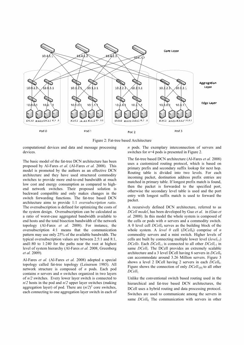
Figure 2: Fat-tree based Architecture
computational devices and data and message processing devices.
The basic model of the fat-tree DCN architecture has been proposed by Al-Fares et al. (Al-Fares et al. 2008). This model is promoted by the authors as an effective DCN architecture and they have used structured commodity switches to provide more end-to-end bandwidth at much low cost and energy consumption as compared to high-end network switches. Their proposed solution is backward compatible and only makes changes in the switch forwarding functions. The fat-tree based DCN architecture aims to provide 1:1 oversubscription ratio.The oversubscription is defined for optimizing the costs of the system design. Oversubscription can be calculated as a ratio of worst-case aggregated bandwidth available to end hosts and the total bisection bandwidth of the network topology (Al-Fares et al. 2008). For instance, the oversubscription 4:1 means that the communication pattern may use only 25% of the available bandwidth. The typical oversubscription values are between 2.5:1 and 8:1, and1:80 to 1:240 for the paths near the root at highest level of system hierarchy (Al-Fares et al. 2008, Greenberg et al. 2009).
Al-Fares et al. (Al-Fares et al. 2008) adopted a special topology called fat-tree topology (Leiserson 1985). All network structure is composed of n pods. Each pod contains n servers and n switches organized in two layers of n/2 switches. Every lower layer switch is connected to n/2 hosts in the pod and n/2 upper layer switches (making aggregation layer) of pod. There are (n/2)2 core switches, each connecting to one aggregation layer switch in each of
n pods. The exemplary interconnection of servers and switches for n=4 pods is presented in Figure 2.
The fat-tree based DCN architecture (Al-Fares et al. 2008) uses a customized routing protocol, which is based on primary prefix and secondary suffix lookup for next hop. Routing table is divided into two levels. For each incoming packet, destination address prefix entries are matched in primary table. If longest prefix match is found, then the packet is forwarded to the specified port, otherwise the secondary level table is used and the port entry with longest suffix match is used to forward the packet.
A recursively defined DCN architecture, referred to as DCell model, has been developed by Guo et al. in (Guo etal. 2008). In this model the whole system is composed of the cells or pods with n servers and a commodity switch. A 0 level cell DCell0 serves as the building block of the whole system. A level 0 cell (DCell0) comprise of ncommodity servers and a mini switch. Higher levels of cells are built by connecting multiple lower level (levell-1)DCells. Each DCelll-1 is connected to all other DCelll-1 in same DCelll. The DCell provides an extremely scalable architecture and a 3 level DCell having 6 servers in DCell0can accommodate around 3.26 Million servers. Figure 3 shows a level 2 DCell having 2 servers in each DCell0.Figure shows the connection of only DCell1[0] to all other DCell1.
Unlike the conventional switch based routing used in the hierarchical and fat-tree based DCN architectures, the DCell uses a hybrid routing and data processing protocol. Switches are used to communicate among the servers in same DCell0. The communication with servers in other
Figure 3: Level 2 DCell (DCell2)
DCells is performed by servers acting as routers. In fact just computational servers are also considered as the routers in the system. The DCellRouting scheme is used in the DCell architecture to compute the path from the source to destination node exploiting divide and conquer approach. Source node (s) computes the path from s to destination (d). The link that interconnects the DCells that contain the s and d in the same level is calculated first and then sub-paths from s to link and from link to d is calculated. Combination of both sub-paths gives the path from s to d. The DCellRouting is not a minimum hop routing scheme therefore, the calculated route has more hops than the shortest path routing.
Popa et al. (Popa et al. 2010) present a methodology of the theoretical approximation of cost of different DCN architectures by using the system performance metrics, namely network latency and capacity. The authors also presented a cost comparison of different DCN
architectures by using current market price of energy and equipment. Gyarmati et al. (Gyarmati et al. 2010) compared the energy consumption in different DCN architectures. The authors have derived the results from mathematical analysis by considering the number of servers, total number of ports, and switches. They considered the static predefined measurement of energy consumption for devices. Chen et al. (Chen et al. 2010) have surveyed the routing protocols used in the major DCN architecture models and have addressed some open questions and security issues in DCN routing. Implementation of DCN architectures would be discussed in next section.
SIMULATION EXPERIMENTS
Environment
The main aim of a simple empirical simulation analysis presented in this section is to provide the insight of different DCN architectures in a realistic manner. Two
DCN core architectural models, namely the fat-tree based architecture (Al-Fares et al. 2008) and recursively build architecture (Guo et al. 2008), have been used for the simulation of the multi-level DCN performance. These models have been adapted to illustrate the efficiencies of different routing protocols (Guo et al. 2009; Greenberg et al. 2009). We used ns-3 discrete-event network simulator for implementing the considered DCN architectures (ns-3 2012). The ns-3 simulator allows to model various realistic scenarios. The most important salient features of ns-3 simulator are: (a) an implementation of real IP addresses, (b) BSD socket interface, (c) multiple installations of interfaces on a single node, (d) real network bytes are contained in simulated packets, and (e)packet traces can be captured and analyzed using tools like Wireshark. In this work, the DCN architectures uses: (a) the customized addressing scheme, (b) the customized routing protocols that strongly depend on the applied addressing scheme (e.g., (Al-Fares et al. 2008)). Therefore, ns-3 deemed as the most appropriate network simulator for our work. One of the major drawbacks of using the ns-3 simulator is a lack of the switch module in ns-3 library. and conventional Ethernet protocol cannot be implemented. Therefore, we configured Point-To-Point links for the connection of switches and nodes.
Implementation Details
The considered DCN architectures have been implemented using the multiple network interfaces at each node as required. In the case of fat-tree based topology, the primary and secondary routing tables are generated dynamically based on the number of pods. The realistic IP addresses have been generated for all nodes in the system and linked to appropriate lower layer switches. Three layers of switches have been created, interconnected properly and populated with primary and secondary routing tables. We have customized the general simulator model by extending it with an additional routing module for processing two layered based primary and secondary routing tables in ns-3.
In the DCell architecture, the DCellRouting protocol is implemented to generate the end-to-end path at source node. We have specified a scalable addressing protocol for this model. The DCellRouting lacks the generic protocol description and a specific routing scenario is discussed by authors. We have used source based routing to route the packets from the source to destination.
Simulation Results
We have simulated the fat-tree based DCN architecture using its customized routing algorithm. The DCell architecture is implemented with the DCell’s customized topology and addressing scheme. However, we have used built-in source based routing module i.e., Nix-Vector routing (Nix-Vector 2012). We have used uniform
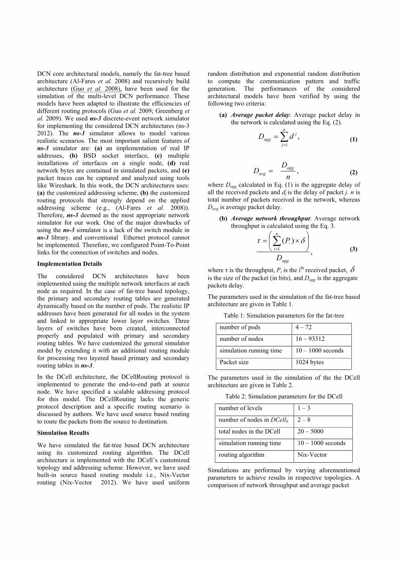
random distribution and exponential random distribution to compute the communication pattern and traffic generation. The performances of the considered architectural models have been verified by using the following two criteria:
(a) Average packet delay: Average packet delay in the network is calculated using the Eq. (2).
,1
n
j
jagg dD (1)
,n
DD agg
avg (2)
where Dagg calculated in Eq. (1) is the aggregate delay of all the received packets and dj is the delay of packet j. n is total number of packets received in the network, whereasDavg is average packet delay.
(b) Average network throughput: Average network throughput is calculated using the Eq. 3.
,)(
1
agg
n
i
D
Pi
(3)
where is the throughput, Pi is the ith received packet, is the size of the packet (in bits), and Dagg is the aggregate packets delay.
The parameters used in the simulation of the fat-tree based architecture are given in Table 1.
Table 1: Simulation parameters for the fat-tree
number of pods 4 – 72
number of nodes 16 – 93312
simulation running time 10 – 1000 seconds
Packet size 1024 bytes
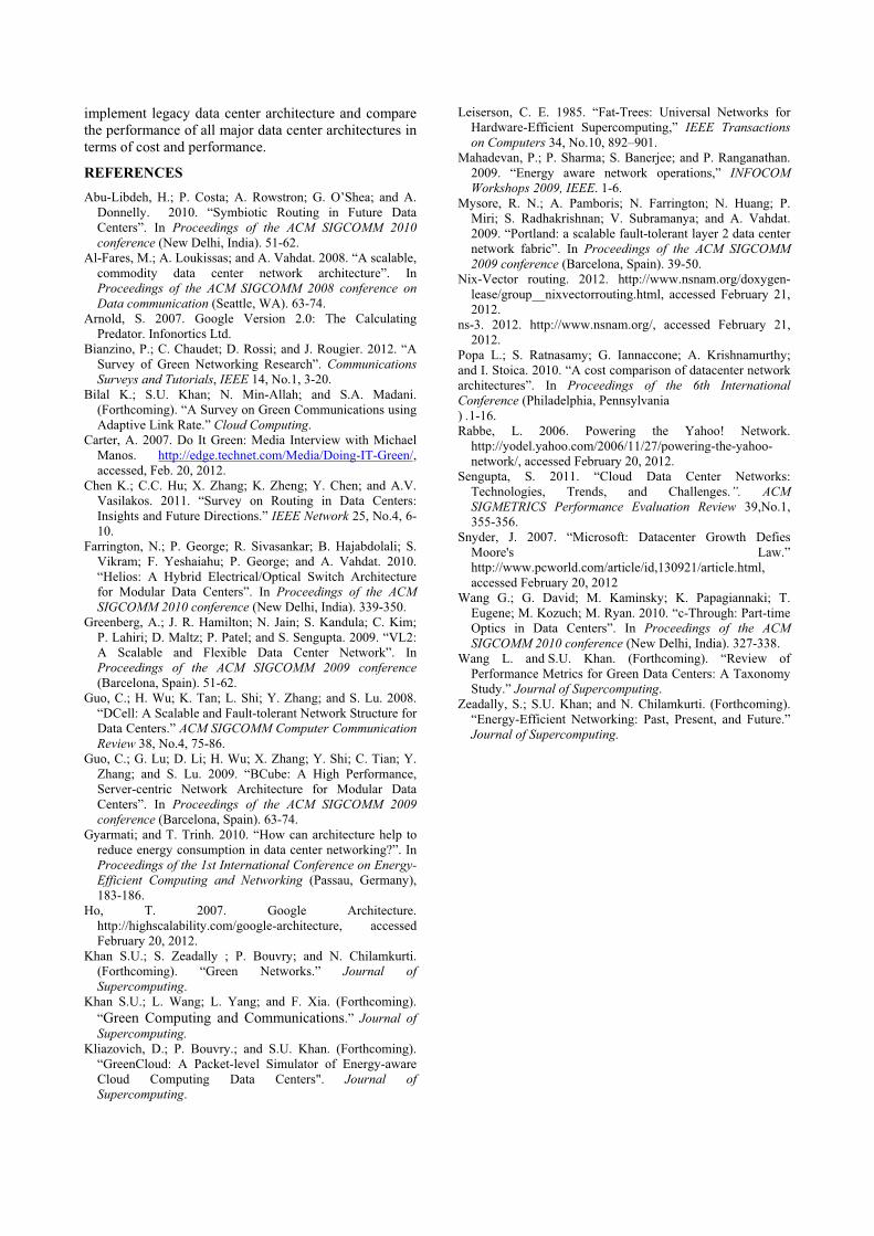
The parameters used in the simulation of the the DCell architecture are given in Table 2.
Table 2: Simulation parameters for the DCell
number of levels 1 – 3
number of nodes in DCell0 2 – 8
total nodes in the DCell 20 – 5000
simulation running time 10 – 1000 seconds
routing algorithm Nix-Vector
Simulations are performed by varying aforementioned parameters to achieve results in respective topologies. A comparison of network throughput and average packet

0.02
0.04
0.06
0.08
20 70 150
500
1000
2000
5000
agePa
cket
Delay
(ms)
Average Packet delay using ExponentialRandom Traffic Distribution
Figure 4: Throughput and average Packet Delay using Exponential Random Traffic distribution
0.020.030.040.050.060.070.08
20 70 150
500
1000
2000
5000
AveragePacket
Delay(m
s)
Nodes
Average Packet delay using UniformRandom Traffic Distribution
FAT
DCell
Figure 5: Throughput and average Packet Delay using Uniform Random Traffic distribution
delay for both of the aforementioned architectures is shown in Figure 4. Communication pattern and traffic generation is achieved by using exponential random distribution. Figure 5 shows the comparison of network throughput and average packet delay using uniform random communication pattern and traffic generation.
The simulation results show that the fat-tree topology is consistent in throughput and a slight degradation in throughput is observed when the number of nodes is increased. More than 1 Million packets are exchanged in simulating the fat-tree topology with 72 pods and 93,312 serves in 100 seconds. The average network throughput for 256 to 93,000 nodes was observed in a range from 169Mbps to 165Mbps respectively. The average packet delay in the fat-tree based architecture is also observed to be nearly consistent. The observed average packet delay falls in the range from 0.043 ms to 0.049 ms for 4 pods to 72 pods simulation respectively. The observed results depict that the performance of the fat- tree based architecture is independent of the number of nodes.
In case of the DCell architecture, we have used Nix-Vector source based routing. The observed results show a decline in curve when the number of nodes is
increased. The DCell outperforms the fat-tree based architecture for small number of nodes but gradually declines in terms of throughput when number of nodes and DCell levels increase. A similar behavior is observed in average packet delay. The results show that the throughput decreases greatly as the number of nodes increase from 20 to 500. However, results show a minor curve declination after the number of nodes reaches 500.
The results show that the fat-tree base architecture outperforms the DCell in terms of average network throughput and packet latency.
CONCLUSIONS
We presented a comparison of the major data center architectures that addresses the issues of network scalability and oversubscription. We simulated the performance of DCN architectures in various realistic scenarios. The simulation results show that the fat-tree based DCN architecture performs better than the DCell DCN architecture in terms of average network throughput and latency. In our future work, we plan to implement the DCell customized routing scheme and compare its performance with shortest path routing and the fat-tree based routing schemes. We will also
115145175205235265295
20 70 150
500
1000
2000
5000
Throughp
utMbp
s
Nodes
Throughput Comparison using ExponentialRandom Traffic Distribution
FAT
DCell
115145175205235265295
20 70 150
500
1000
2000
5000
Throughp
utMbp
s
Nodes
Throughput Comparison using UniformRandom traffic Distribution
FAT
DCell
implement legacy data center architecture and compare the performance of all major data center architectures in terms of cost and performance.
REFERENCES Abu-Libdeh, H.; P. Costa; A. Rowstron; G. O’Shea; and A.
Donnelly. 2010. “Symbiotic Routing in Future Data Centers”. In Proceedings of the ACM SIGCOMM 2010 conference (New Delhi, India). 51-62.
Al-Fares, M.; A. Loukissas; and A. Vahdat. 2008. “A scalable, commodity data center network architecture”. In Proceedings of the ACM SIGCOMM 2008 conference on Data communication (Seattle, WA). 63-74.
Arnold, S. 2007. Google Version 2.0: The Calculating Predator. Infonortics Ltd.
Bianzino, P.; C. Chaudet; D. Rossi; and J. Rougier. 2012. “A Survey of Green Networking Research”. Communications Surveys and Tutorials, IEEE 14, No.1, 3-20.
Bilal K.; S.U. Khan; N. Min-Allah; and S.A. Madani. (Forthcoming). “A Survey on Green Communications using Adaptive Link Rate.” Cloud Computing.
Carter, A. 2007. Do It Green: Media Interview with Michael Manos. http://edge.technet.com/Media/Doing-IT-Green/,accessed, Feb. 20, 2012.
Chen K.; C.C. Hu; X. Zhang; K. Zheng; Y. Chen; and A.V. Vasilakos. 2011. “Survey on Routing in Data Centers: Insights and Future Directions.” IEEE Network 25, No.4, 6-10.
Farrington, N.; P. George; R. Sivasankar; B. Hajabdolali; S. Vikram; F. Yeshaiahu; P. George; and A. Vahdat. 2010. “Helios: A Hybrid Electrical/Optical Switch Architecture for Modular Data Centers”. In Proceedings of the ACM SIGCOMM 2010 conference (New Delhi, India). 339-350.
Greenberg, A.; J. R. Hamilton; N. Jain; S. Kandula; C. Kim; P. Lahiri; D. Maltz; P. Patel; and S. Sengupta. 2009. “VL2: A Scalable and Flexible Data Center Network”. In Proceedings of the ACM SIGCOMM 2009 conference (Barcelona, Spain). 51-62.
Guo, C.; H. Wu; K. Tan; L. Shi; Y. Zhang; and S. Lu. 2008. “DCell: A Scalable and Fault-tolerant Network Structure for Data Centers.” ACM SIGCOMM Computer Communication Review 38, No.4, 75-86.
Guo, C.; G. Lu; D. Li; H. Wu; X. Zhang; Y. Shi; C. Tian; Y. Zhang; and S. Lu. 2009. “BCube: A High Performance, Server-centric Network Architecture for Modular Data Centers”. In Proceedings of the ACM SIGCOMM 2009 conference (Barcelona, Spain). 63-74.
Gyarmati; and T. Trinh. 2010. “How can architecture help to reduce energy consumption in data center networking?”. In Proceedings of the 1st International Conference on Energy-Efficient Computing and Networking (Passau, Germany), 183-186.
Ho, T. 2007. Google Architecture. http://highscalability.com/google-architecture, accessed February 20, 2012.
Khan S.U.; S. Zeadally ; P. Bouvry; and N. Chilamkurti. (Forthcoming). “Green Networks.” Journal of Supercomputing.
Khan S.U.; L. Wang; L. Yang; and F. Xia. (Forthcoming). “Green Computing and Communications.” Journal of Supercomputing.
Kliazovich, D.; P. Bouvry.; and S.U. Khan. (Forthcoming). “GreenCloud: A Packet-level Simulator of Energy-aware Cloud Computing Data Centers". Journal of Supercomputing.
Leiserson, C. E. 1985. “Fat-Trees: Universal Networks for Hardware-Efficient Supercomputing,” IEEE Transactions on Computers 34, No.10, 892–901.
Mahadevan, P.; P. Sharma; S. Banerjee; and P. Ranganathan. 2009. “Energy aware network operations,” INFOCOMWorkshops 2009, IEEE. 1-6.
Mysore, R. N.; A. Pamboris; N. Farrington; N. Huang; P. Miri; S. Radhakrishnan; V. Subramanya; and A. Vahdat. 2009. “Portland: a scalable fault-tolerant layer 2 data center network fabric”. In Proceedings of the ACM SIGCOMM 2009 conference (Barcelona, Spain). 39-50.
Nix-Vector routing. 2012. http://www.nsnam.org/doxygen-lease/group__nixvectorrouting.html, accessed February 21, 2012.
ns-3. 2012. http://www.nsnam.org/, accessed February 21, 2012.
Popa L.; S. Ratnasamy; G. Iannaccone; A. Krishnamurthy; and I. Stoica. 2010. “A cost comparison of datacenter network architectures”. In Proceedings of the 6th International Conference (Philadelphia, Pennsylvania ) .1-16. Rabbe, L. 2006. Powering the Yahoo! Network.
http://yodel.yahoo.com/2006/11/27/powering-the-yahoo-network/, accessed February 20, 2012.
Sengupta, S. 2011. “Cloud Data Center Networks: Technologies, Trends, and Challenges.”. ACM SIGMETRICS Performance Evaluation Review 39,No.1, 355-356.
Snyder, J. 2007. “Microsoft: Datacenter Growth Defies Moore's Law.” http://www.pcworld.com/article/id,130921/article.html,accessed February 20, 2012
Wang G.; G. David; M. Kaminsky; K. Papagiannaki; T. Eugene; M. Kozuch; M. Ryan. 2010. “c-Through: Part-time Optics in Data Centers”. In Proceedings of the ACM SIGCOMM 2010 conference (New Delhi, India). 327-338.
Wang L. and S.U. Khan. (Forthcoming). “Review of Performance Metrics for Green Data Centers: A Taxonomy Study.” Journal of Supercomputing.
Zeadally, S.; S.U. Khan; and N. Chilamkurti. (Forthcoming). “Energy-Efficient Networking: Past, Present, and Future.” Journal of Supercomputing.
Related Documents