Energies 2022, 15, 4930. https://doi.org/10.3390/en15134930 www.mdpi.com/journal/energies Review A Comparative Review of Lead‐Acid, Lithium‐Ion and Ultra‐Capacitor Technologies and Their Degradation Mechanisms Ashleigh Townsend * and Rupert Gouws School of Electrical, Electronic and Computer Engineering, North West University, Potchefstroom 2520, South Africa; [email protected] * Correspondence: [email protected] Abstract: As renewable energy sources, such as solar systems, are becoming more popular, the focus is moving into more effective utilization of these energy sources and harvesting more energy for intermittency reduction in this renewable source. This is opening up a market for methods of energy storage and increasing interest in batteries, as they are, as it stands, the foremost energy storage device available to suit a wide range of requirements. This interest has brought to light the downfalls of batteries and resultantly made room for the investigation of ultra‐capacitors as a solution to these downfalls. One of these downfalls is related to the decrease in capacity, and temperamentality thereof, of a battery when not used precisely as stated by the supplier. The usable capacity is reliant on the complete discharge/charge cycles the battery can undergo before a 20% degradation in its specified capacity is observed. This article aims to investigate what causes this degradation, what aggravates it and how the degradation affects the usage of the battery. This investigation will lead to the identification of a gap in which this degradation can be decreased, prolonging the usage and increasing the feasibility of the energy storage devices. Keywords: lead acid battery; lithium‐ion battery; ultra‐capacitor; battery degradation; sulfation; stratification; renewable energy sources; energy storage; capacity decay/attenuation; charge/discharge cycles 1. Introduction Energy storage is a key component required in the diversification of energy sources. Renewable energy source advances [1], as well as recent grid power regression [2], has highlighted the necessity of energy storage due to intermittency. Renewable energy is in‐ termittent by nature, where the availability and extent of availability is limited by the source [3]. Intermittency refers to the discontinuous availability of electrical energy due to external factors that cannot be controlled and that occur in generating sources that vary over a short‐time period [4]. Renewable sources that are intermittent include solar, wind, tidal and wave [5,6]; solar and tidal are relatively predictable due to weather, tidal and diurnal patterns [7]. The causes of intermittency in solar power are due to solar intensity variances throughout the day, and in different locations, as well as cloud cover [8,9]; wind power is considered highly intermittent as it has more variances with respect to wind speed, air density and turbine characteristics. These factors are further influenced by location [8,9]. Tidal (and wave) power is significantly more predictable as tides occur at expected times [7]. How‐ ever, all of these generation sources are known as non‐dispatchable sources as the output is not guaranteed at any moment to meet fluctuating energy demands [4]. Renewable energy is not only dependent on the availability; it is also dependant on the magnitude of the generative source of that energy [10]. If the source is insufficient (the Citation: Townsend, A.; Gouws, R. A Comparative Review of Lead‐Acid, Lithium‐Ion and Ultra‐Capacitor Technologies and Their Degradation Mechanisms. Energies 2022, 15, 4930. https://doi.org/10.3390/en15134930 Academic Editors: Marcin Wołowicz, Krzysztof Badyda and Piotr Krawczyk Received: 24 May 2022 Accepted: 23 June 2022 Published: 5 July 2022 Publisher’s Note: MDPI stays neu‐ tral with regard to jurisdictional claims in published maps and institu‐ tional affiliations. Copyright: © 2022 by the authors. Li‐ censee MDPI, Basel, Switzerland. This article is an open access article distributed under the terms and con‐ ditions of the Creative Commons At‐ tribution (CC BY) license (https://cre‐ ativecommons.org/licenses/by/4.0/).

Welcome message from author
This document is posted to help you gain knowledge. Please leave a comment to let me know what you think about it! Share it to your friends and learn new things together.
Transcript
Energies 2022, 15, 4930. https://doi.org/10.3390/en15134930 www.mdpi.com/journal/energies
Review
A Comparative Review of Lead‐Acid, Lithium‐Ion
and Ultra‐Capacitor Technologies and Their
Degradation Mechanisms
Ashleigh Townsend * and Rupert Gouws
School of Electrical, Electronic and Computer Engineering, North West University,
Potchefstroom 2520, South Africa; [email protected]
* Correspondence: [email protected]
Abstract: As renewable energy sources, such as solar systems, are becoming more popular, the focus
is moving into more effective utilization of these energy sources and harvesting more energy for
intermittency reduction in this renewable source. This is opening up a market for methods of energy
storage and increasing interest in batteries, as they are, as it stands, the foremost energy storage
device available to suit a wide range of requirements. This interest has brought to light the downfalls
of batteries and resultantly made room for the investigation of ultra‐capacitors as a solution to these
downfalls. One of these downfalls is related to the decrease in capacity, and temperamentality
thereof, of a battery when not used precisely as stated by the supplier. The usable capacity is reliant
on the complete discharge/charge cycles the battery can undergo before a 20% degradation in its
specified capacity is observed. This article aims to investigate what causes this degradation, what
aggravates it and how the degradation affects the usage of the battery. This investigation will lead
to the identification of a gap in which this degradation can be decreased, prolonging the usage and
increasing the feasibility of the energy storage devices.
Keywords: lead acid battery; lithium‐ion battery; ultra‐capacitor; battery degradation; sulfation;
stratification; renewable energy sources; energy storage; capacity decay/attenuation;
charge/discharge cycles
1. Introduction
Energy storage is a key component required in the diversification of energy sources.
Renewable energy source advances [1], as well as recent grid power regression [2], has
highlighted the necessity of energy storage due to intermittency. Renewable energy is in‐
termittent by nature, where the availability and extent of availability is limited by the
source [3]. Intermittency refers to the discontinuous availability of electrical energy due
to external factors that cannot be controlled and that occur in generating sources that vary
over a short‐time period [4].
Renewable sources that are intermittent include solar, wind, tidal and wave [5,6];
solar and tidal are relatively predictable due to weather, tidal and diurnal patterns [7].
The causes of intermittency in solar power are due to solar intensity variances throughout
the day, and in different locations, as well as cloud cover [8,9]; wind power is considered
highly intermittent as it has more variances with respect to wind speed, air density and
turbine characteristics. These factors are further influenced by location [8,9]. Tidal (and
wave) power is significantly more predictable as tides occur at expected times [7]. How‐
ever, all of these generation sources are known as non‐dispatchable sources as the output
is not guaranteed at any moment to meet fluctuating energy demands [4].
Renewable energy is not only dependent on the availability; it is also dependant on
the magnitude of the generative source of that energy [10]. If the source is insufficient (the
Citation: Townsend, A.; Gouws, R.
A Comparative Review of
Lead‐Acid, Lithium‐Ion and
Ultra‐Capacitor Technologies and
Their Degradation Mechanisms.
Energies 2022, 15, 4930.
https://doi.org/10.3390/en15134930
Academic Editors: Marcin
Wołowicz, Krzysztof Badyda
and Piotr Krawczyk
Received: 24 May 2022
Accepted: 23 June 2022
Published: 5 July 2022
Publisher’s Note: MDPI stays neu‐
tral with regard to jurisdictional
claims in published maps and institu‐
tional affiliations.
Copyright: © 2022 by the authors. Li‐
censee MDPI, Basel, Switzerland.
This article is an open access article
distributed under the terms and con‐
ditions of the Creative Commons At‐
tribution (CC BY) license (https://cre‐
ativecommons.org/licenses/by/4.0/).
Energies 2022, 15, 4930 2 of 30
system design is not large enough or has incorrect parameters, or the supply is intermit‐
tent [11]) no significant power will be generated, and if the load requirement is less than
the source capacity, the remainder is lost [12]. By having a renewable source provide the
required load with any remainder supplying an energy storage device, i.e., hybrid energy
storage systems (HESS), the renewable source can be utilized on a larger scale and more
efficiently [13].
Currently there exists a multitude of energy storage technologies: pumped‐hydro
and compressed‐air energy storage facilities, flywheels, superconducting magnetic stor‐
age and electrochemical energy storage [12]. The first four options are limited by their site‐
dependence [14–16], capacity [17,18] or response capabilities [15,19], whereas electro‐
chemical energy storage (such as batteries and supercapacitors) offers more flexibility in
capacity [20], siting and rapid response capabilities [21] that meet a larger range of appli‐
cations [22] as compared to the other types of energy storage. Due to their versatility, high
energy density, efficiency and cost, batteries have seen great growth in their application
in energy storage systems [23].
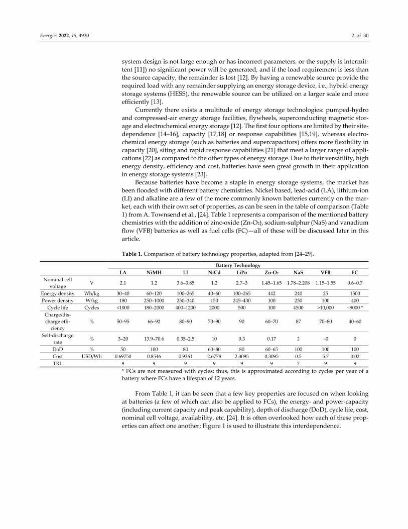
Because batteries have become a staple in energy storage systems, the market has
been flooded with different battery chemistries. Nickel based, lead‐acid (LA), lithium‐ion
(LI) and alkaline are a few of the more commonly known batteries currently on the mar‐
ket, each with their own set of properties, as can be seen in the table of comparison (Table
1) from A. Townsend et al., [24]. Table 1 represents a comparison of the mentioned battery
chemistries with the addition of zinc‐oxide (Zn‐O2), sodium‐sulphur (NaS) and vanadium
flow (VFB) batteries as well as fuel cells (FC)—all of these will be discussed later in this
article.
Table 1. Comparison of battery technology properties, adapted from [24–29].
Battery Technology
LA NiMH LI NiCd LiPo Zn‐O2 NaS VFB FC
Nominal cell
voltage V 2.1 1.2 3.6–3.85 1.2 2.7–3 1.45–1.65 1.78–2.208 1.15–1.55 0.6–0.7
Energy density Wh/kg 30–40 60–120 100–265 40–60 100–265 442 240 25 1500
Power density W/kg 180 250–1000 250–340 150 245–430 100 230 100 400
Cycle life Cycles <1000 180–2000 400–1200 2000 500 100 4500 >10,000 ⁓9000 *
Charge/dis‐
charge effi‐
ciency
% 50–95 66–92 80–90 70–90 90 60–70 87 70–80 40–60
Self‐discharge
rate % 3–20 13.9–70.6 0.35–2.5 10 0.3 0.17 2 ⁓0 0
DoD % 50 100 80 60–80 80 60–65 100 100 100
Cost USD/Wh 0.69750 0.8546 0.9361 2.6778 2.3095 0.3095 0.5 5.7 0.02
TRL 9 9 9 9 9 9 7 9 9
* FCs are not measured with cycles; thus, this is approximated according to cycles per year of a
battery where FCs have a lifespan of 12 years.
From Table 1, it can be seen that a few key properties are focused on when looking
at batteries (a few of which can also be applied to FCs), the energy‐ and power‐capacity
(including current capacity and peak capability), depth of discharge (DoD), cycle life, cost,
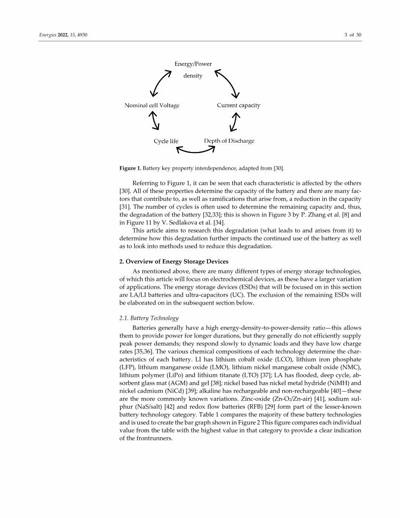
nominal cell voltage, availability, etc. [24]. It is often overlooked how each of these prop‐
erties can affect one another; Figure 1 is used to illustrate this interdependence.
Energies 2022, 15, 4930 3 of 30
Figure 1. Battery key property interdependence, adapted from [30].
Referring to Figure 1, it can be seen that each characteristic is affected by the others
[30]. All of these properties determine the capacity of the battery and there are many fac‐
tors that contribute to, as well as ramifications that arise from, a reduction in the capacity
[31]. The number of cycles is often used to determine the remaining capacity and, thus,
the degradation of the battery [32,33]; this is shown in Figure 3 by P. Zhang et al. [8] and
in Figure 11 by V. Sedlakova et al. [34].
This article aims to research this degradation (what leads to and arises from it) to
determine how this degradation further impacts the continued use of the battery as well
as to look into methods used to reduce this degradation.
2. Overview of Energy Storage Devices
As mentioned above, there are many different types of energy storage technologies,
of which this article will focus on electrochemical devices, as these have a larger variation
of applications. The energy storage devices (ESDs) that will be focused on in this section
are LA/LI batteries and ultra‐capacitors (UC). The exclusion of the remaining ESDs will
be elaborated on in the subsequent section below.
2.1. Battery Technology
Batteries generally have a high energy‐density‐to‐power‐density ratio—this allows
them to provide power for longer durations, but they generally do not efficiently supply
peak power demands; they respond slowly to dynamic loads and they have low charge
rates [35,36]. The various chemical compositions of each technology determine the char‐
acteristics of each battery. LI has lithium cobalt oxide (LCO), lithium iron phosphate
(LFP), lithium manganese oxide (LMO), lithium nickel manganese cobalt oxide (NMC),
lithium polymer (LiPo) and lithium titanate (LTO) [37]; LA has flooded, deep cycle, ab‐
sorbent glass mat (AGM) and gel [38]; nickel based has nickel metal hydride (NiMH) and
nickel cadmium (NiCd) [39]; alkaline has rechargeable and non‐rechargeable [40]—these
are the more commonly known variations. Zinc‐oxide (Zn‐O2/Zn‐air) [41], sodium sul‐
phur (NaS/salt) [42] and redox flow batteries (RFB) [29] form part of the lesser‐known
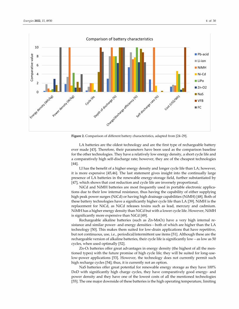
battery technology category. Table 1 compares the majority of these battery technologies
and is used to create the bar graph shown in Figure 2 This figure compares each individual
value from the table with the highest value in that category to provide a clear indication
of the frontrunners.
Energies 2022, 15, 4930 4 of 30
Figure 2. Comparison of different battery characteristics, adapted from [24–29].
LA batteries are the oldest technology and are the first type of rechargeable battery
ever made [43]. Therefore, their parameters have been used as the comparison baseline
for the other technologies. They have a relatively low energy density, a short cycle life and
a comparatively high self‐discharge rate; however, they are of the cheapest technologies
[44].
LI has the benefit of a higher energy density and longer cycle life than LA; however,
it is more expensive [45,46]. The last statement gives insight into the continually large
presence of LA batteries in the renewable energy‐storage field, further substantiated by
[47], which shows that cost reduction and cycle life are inversely proportional.
NiCd and NiMH batteries are most frequently used in portable electronic applica‐
tions due to their low internal resistance, thus having the capability of either supplying
high peak power surges (NiCd) or having high drainage capabilities (NiMH) [48]. Both of
these battery technologies have a significantly higher cycle life than LA [39]. NiMH is the
replacement for NiCd, as NiCd releases toxins such as lead, mercury and cadmium.
NiMH has a higher energy density than NiCd but with a lower cycle life. However, NiMH
is significantly more expensive than NiCd [49].
Rechargeable alkaline batteries (such as Zn‐MnO2) have a very high internal re‐
sistance and similar power‐ and energy densities—both of which are higher than the LA
technology [50]. This makes them suited for low‐drain applications that have repetitive,
but not continuous, use, i.e., periodical/intermittent use items [51]. Although these are the
rechargeable version of alkaline batteries, their cycle life is significantly low—as low as 50
cycles, when used optimally [52].
Zn‐O2 batteries offer great advantages in energy density (the highest of all the men‐
tioned types) with the future promise of high cycle life; they will be suited for long‐use‐
low‐power applications [53]. However, the technology does not currently permit such
high recharge cycles [54]; thus, it is currently not an option.
NaS batteries offer great potential for renewable energy storage as they have 100%
DoD with significantly high charge cycles, they have comparatively good energy‐ and
power density and they have one of the lowest costs of all the mentioned technologies
[55]. The one major downside of these batteries is the high operating temperature, limiting
0
2
4
6
8
10
Comparative value
Comparison of battery characteristics
Pb‐acid
Li‐ion
NiMH
Ni‐Cd
LiPo
Zn‐O2
NaS
VFB
FC
Energies 2022, 15, 4930 5 of 30
their applications [23,56]. Another factor to consider is that these batteries have a TRL of
7 and are thus commercially unavailable.
In a traditional battery, the electrons travel through the electrolyte between the elec‐
trodes; in an RFB the electrodes are the electrolytes [57]. RFBs are generally divided into
two categories—true or hybrid [58]; the main difference is that hybrid RFBs have one ox‐
idation state of the redox couples stored on the electrode surface as a solid [59]. Vanadium‐
vanadium and iron‐chromium are examples of true RFBs and zinc‐bromine and zinc‐chlo‐
rine are examples of hybrid RFBs [27]. What makes these batteries so attractive is that they
do not degrade as an LI battery would. Thus, they have a significantly longer lifespan [57],
and they are easily scalable—the size of the tanks just has to be increased (volume of elec‐
trolyte used) [60]. They are considered safer than LI as the electrolyte is not flammable,
and consequently they do not experience thermal runaway; they also have a very low,
almost zero, self‐discharge due to the active materials being separated when they are not
being used [27]. On the downside, these batteries are not suited for portable applications
[57], they have lower energy capacity and they are significantly more expensive due to
the initial infrastructure setup requirements [57,61,62].
An alternative to battery technology is seen in the form of FCs [63]. There are various
types of FCs—polymer electrolyte membrane (PEMFC), alkaline (AFC), phosphoric acid
(PAFC), molten carbonate (MCFC) and solid oxide (SOFC) [64]. Each of these FCs have
various differences: PEMFC and SOFC utilize a solid electrolyte whilst the others use a
liquid variation (solid electrolytes have the advantage of less corrosion [65]). In order of
being mentioned, operating temperatures and stack sizes increase, whereas susceptibility
to carbon monoxide or dioxide poisoning decreases [64]. MCFC and SOFC have operating
temperatures of 600–700 °C and 500–1000 °C [64], respectively, compared to a less than
200 °C operating temperature of the remaining variations [66]. Increased operating tem‐
peratures increase the start‐up time and corrosiveness of the components but decrease the
necessity for external fuel reformation or electrolysis. PEMFC and PAFC require a pre‐
cious‐metal catalyst which increases the cost significantly [64]. Susceptibility to poisoning
[67], catalyst type [68], external fuel reformation or electrolysis requirements and higher
operating temperatures all lead to an increase in the overall cost of the FC (higher operat‐
ing temperatures increase corrosiveness and degradation of the components) [67].
FCs have the advantage of high energy density (similar to that of LI batteries), can be
carbon‐neutral (by‐product of cell is water and heat [64]) [69], its capacity does not deplete
during “discharge” (it supplies a constant capacity throughout) and “recharging” is as
quick as a refuel (around 3 min) [70]. Most FCs use some or other form of hydrogen as
fuel as hydrogen is abundant, but its acquisition requires either electrolysis or reformation
[63]—herein lies the method of storing renewable energy, i.e., generate and store hydro‐
gen. Hydrogen can be stored and transported in either liquid or gas form. The liquid form
requires cryogenic temperatures and the gas form requires high compression rates [71].
Both have high energy losses (40% and 13%, respectively) which are large in comparison
to those related to the transmission of electrical energy (±9%) [72,73]. Both methods of
generation as well as the storage of hydrogen require significant infrastructure, which in‐
creases the initial investment for FC use [74]. Additionally, hydrogen can be highly flam‐
mable, which adds another investment level to the infrastructure requirement [75,76].
Summarizing the main disadvantages of the above technologies, in relation to renew‐
able energy storage applications, NiCd and NiMH are generally made for applications
requiring small current capacities; rechargeable alkaline and Zn‐air have too few recharge
cycles; NaS batteries can only be used in applications with low environmental tempera‐
ture, but most importantly, they are not commercially available; and RFBs and FCs require
too large of an initial capital investment and maintenance requirements. Initial cost, infra‐
structure and maintenance requirements, replacement frequency and operating tempera‐
tures give insight into why the above ESDs are not utilized more in the renewable energy
storage industry, leaving LA and LI batteries. The acquisition and maintenance factors
increase the complexity of ESD use [77]. LI and LA are most commonly used (and
Energies 2022, 15, 4930 6 of 30
preferred) with renewable energy systems [78] (mainly due to their simplicity in terms of
acquisition and maintenance) and will therefore be the focus of this article. Both LI and
LA have multiple variations that differ in electrode chemistry, electrolyte viscosity and
separator type. These variations will be discussed further.
2.1.1. Lead Acid Battery Technologies
LA batteries have sealed and flooded types—the former requires minimal mainte‐
nance, whereas the latter requires a larger amount of maintenance, more specifically in
terms of electrolyte top‐up [79]. However, for this article sealed LA batteries will be the
focus as they offer better characteristics on all fronts except cost—the cost of a flooded LA
battery is understandably lower than sealed as it requires maintenance by the user [79].
Deep‐cycle LA batteries have thicker plates (than non‐deep cycle types). This in‐
creases the density of the active material, increasing the energy density. More active ma‐
terial means deeper depth of discharge potential; however, this does not increase the cycle
life [80].
Absorbent glass mat (AGM) LA batteries have a separator that is made of glass fibre
[81]. This mat is only soaked in enough electrolyte to drench the mat. The mat allows
gasses from the chemical reaction to pass through and oxidize/reduce the opposing elec‐
trode. This gas would otherwise float to the top in the form of bubbles being released and
lost into the atmosphere [49]. As this is a sealed battery [82], no top‐up is required, allow‐
ing for minimal maintenance and a more robust design where leakage of the electrolyte
does not occur, and the battery can be stored and used in any orientation [83]. This battery
is often referred to as a valve‐regulated‐lead‐acid (VRLA) due to the use of a blow‐off
valve intended to prevent over‐pressurization of the battery from rapid/deep dis‐/re‐
charge [84].
Another advantage of AGM batteries is that the mat allows for significant compres‐
sion, increasing energy density as compared to similar gel and liquid variations [85]. The
mat also prevents vertical movement of the electrolyte; when the flooded variation is
stored discharged, the acid molecules will gather at the bottom of the battery and when
used, the current will then predominantly flow in this region, increasing the rate of dete‐
rioration of the plates [86].
The electrolyte can be replaced with a gel variation, formed through the addition of
silica [87]. This delivers similar benefits to that of the AGM battery, except that the gel
prevents rapid motion of the ions between the electrodes, thus reducing the surge current
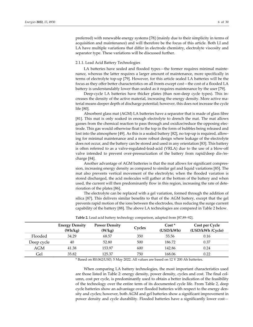
capability of the battery [88]. The above LA technologies are compared in Table 2 below.
Table 2. Lead acid battery technology comparison, adapted from [87,89–92].
Energy Density
(Wh/kg)
Power Density
(W/kg) Cycles
Cost *
(USD/kWh)
Cost per Cycle
(USD/kWh /Cycle)
Flooded 34.29 68.57 350 55.56 0.16
Deep cycle 40 52.80 500 186.72 0.37
AGM 41.38 153.97 600 142.86 0.24
Gel 35.82 125.37 750 168.06 0.22
* Based on R0.062/USD, 5 May 2022. All values are based on 12 V 200 Ah batteries.
When comparing LA battery technologies, the most important characteristics used
are those listed in Table 2: energy density, power density, cycles and cost. The final col‐
umn, cost per cycle, is predominantly used to obtain a better indication of the feasibility
of the technology over the entire term of its documented cycle life. From Table 2, deep
cycle batteries show an advantage over flooded batteries with respect to the energy den‐
sity and cycles; however, both AGM and gel batteries show a significant improvement in
power density and cycle durability. Flooded batteries have a significantly lower cost—
Energies 2022, 15, 4930 7 of 30
more than 30% less—than the other technologies, which, despite their lower energy den‐
sity and cyclability, further justifies their continued large presence in the market.
2.1.2. Lithium‐Ion Battery Technologies
LI batteries operate through the intercalation and deintercalation of LIs into the elec‐
trodes’ chemical structures [93]. Often a lithium salt is added to the electrolyte to reduce
the travelling distance of the LIs, which facilitates faster reactions between the anode and
cathode [94]. The LI battery is discharged once the cathode is fully intercalated with lith‐
ium [93].
A LCO cathode is the most common (and first) type of LI battery [95,96]. Due to its
layered trigonal crystalline structure, cobalt oxide offers the highest energy density of all
the LI variations but possesses a high thermal instability [97]. The anode can overheat,
leading to the cathode releasing oxygen, and the electrolyte is usually also highly flam‐
mable, which exacerbates this fire hazard [98].
LFP, LMO and NMC offer three alternative cathode variations for LI batteries. The
orthorhombic crystalline structure of LFP offers better thermal stability (due to iron‐phos‐
phate’s high temperature tolerance), a longer cycle life and higher power density but also
lower energy density and higher self‐discharge than the cobalt variation [99]. The cubic
crystalline structure of LMO offers very good thermal stability [100], lower internal re‐
sistance and thus high power density (although lower than the other variations), but it
has a lower capacity and cycle life [101]. Finally, NMC (with a trigonal crystalline struc‐
ture) combines the LCO and LMO technologies to obtain a high energy density (still lower
than the cobalt variation), with low internal resistance and thus high power density and
good thermal stability (from LCO) [102].
The liquid electrolyte can be replaced with a thin solid polymer to introduce another
LI variation—LiPo [103]. With a solid electrolyte, the once rigid construction is now flex‐
ible, more compact, lighter and safer, allowing for a higher energy‐ and power density.
However, the polymer tends to be very insulative; thus, a small quantity of gel is added
to improve the conductivity [103,104].
LTO is a variation of the anode that contains a layered monoclinic/olivine crystalline
structure, where the cathode of this variation is manganese oxide or NMC. This construc‐
tion allows for high cycle life and power density but a very low energy density [105]. This
battery has no solid electrolyte interface (SEI) film formation and thus no morphological
degradation; it has a deeper and faster discharge (and charge) than the other variations
and no lithium plating occurrence. Furthermore, it is thermally stable and has better low
temperature functionality than the other battery types [106]. These various technologies
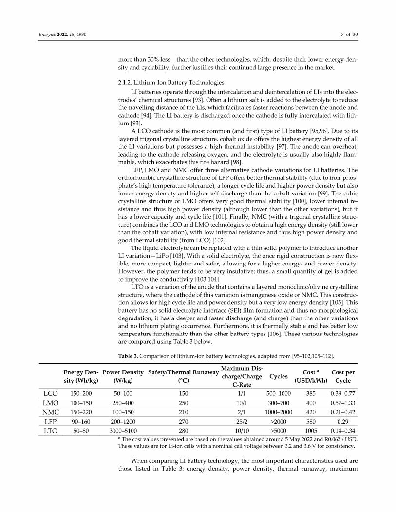
are compared using Table 3 below.
Table 3. Comparison of lithium‐ion battery technologies, adapted from [95–102,105–112].
Energy Den‐
sity (Wh/kg)
Power Density
(W/kg)
Safety/Thermal Runaway
(°C)
Maximum Dis‐
charge/Charge
C‐Rate
Cycles Cost *
(USD/kWh)
Cost per
Cycle
LCO 150–200 50–100 150 1/1 500–1000 385 0.39–0.77
LMO 100–150 250–400 250 10/1 300–700 400 0.57–1.33
NMC 150–220 100–150 210 2/1 1000–2000 420 0.21–0.42
LFP 90–160 200–1200 270 25/2 >2000 580 0.29
LTO 50–80 3000–5100 280 10/10 >5000 1005 0.14–0.34
* The cost values presented are based on the values obtained around 5 May 2022 and R0.062 / USD.
These values are for Li‐ion cells with a nominal cell voltage between 3.2 and 3.6 V for consistency.
When comparing LI battery technology, the most important characteristics used are
those listed in Table 3: energy density, power density, thermal runaway, maximum
Energies 2022, 15, 4930 8 of 30
charge‐ and discharge rates, cycle durability and cost. The cost per cycle is predominantly
used to determine the feasibility of the specified technology. From Table 3, LTO has very
desirable characteristics—it has the highest thermal stability and lowest cost per cycle. Its
high‐power density, coupled with the high c‐rate, allows for fast charge and discharge;
however, the low energy density limits its application to those requiring more immediate
power and not prolonged power. NMC comes in second with respect to cost per cycle; it
has the best energy density (along with LCO), good thermal stability and cycle durability;
it is, however, limited by its c‐rate and power density to applications with lower peak
power requirements. LFP presents a good all‐rounder, with low cost per cycle, high cycle
durability, great thermal stability and discharge rate and comparatively good energy‐ and
power density. LMO offers an improvement on LCO in terms of energy density, thermal
stability and discharge rate. However, LCO has better cyclability, thus lowering the cost
per cycle significantly.
It is important to note that the thermal runaway temperature is a very important fac‐
tor to consider for the application of LI technology, as the battery is sealed, and the elec‐
trolyte can be very volatile in terms of flammability and explosivity [97,113,114].
2.2. Ultra‐Capacitor Technology
An ultra‐capacitor is a capacitor that has an ultra‐high capacitance but with a lower
voltage limit [28]. It is an ESD that essentially combines electrolytic capacitors and re‐
chargeable batteries—storing 10–100 times more energy per unit volume than the former
and being capable of accepting/delivering charge much faster and tolerating significantly
more re‐/discharge cycles than the latter [115].
Different from ordinary capacitors, UC do not use a conventional solid dielectric—
they make use of an electrolyte and isolative membrane and they replace the material of
the plates with one that is (more) porous. The latter allows for a larger effective surface
area, whereas the former allows for the formation of an electric double layer‐ (EDL) and
electrochemical pseudo (EP) capacitance, which together form the total capacitance [116].
When the EDL‐capacitance exceeds the EP‐ capacitance, the UC is referred to as an EDL
capacitor; otherwise, it is an EP capacitor [117]. There are mainly three types of UC: EDL‐
, EP‐ and hybrid capacitors (HC) [118].
In EDL capacitors, the energy storage and release is based on nanoscale charge sep‐
aration at the interface formed between the electrode and electrolyte [26,119]. The charge
storage mechanism is electrostatic (a physical charge transfer), allowing EDL capacitors
to have relatively long life cycles [26,120,121]. EP capacitors store charge on the basis of
faradaic redox reactions (electrochemical storage) involving high energy electrode mate‐
rials. These electrode materials allow supercapacitors with higher energy density at the
price of shorter life cycles and lower charge/discharge rates than EDL capacitors [120,122–
126]. HCs are the hybrid combination of mechanisms from both EDL‐ and EP capacitors
[118].
UC generally have a higher power‐density to energy‐density ratio, allowing them to
provide bursts of high power for short durations. Their internal resistance is very low,
thus allowing for little restriction when providing or receiving power [127]. Opposite to
batteries, UC function best in intermittent high‐power applications and do not fare well
with continued average‐power requirements. They have an almost infinite cycle life and
they have a low self‐discharge rate, but they are relatively expensive as compared to bat‐
tery technology [128].
EDL capacitors have highly porous and conductive electrodes, thus having the ben‐
efit of larger cyclic ability and little degradation due to the highly reversible non‐faradaic
reactions. Their main limitation lies in the requirement of these highly conductive elec‐
trodes, limiting EDL capacitors to carbonaceous materials. EP capacitors have higher en‐
ergy densities, but lower cyclic ability and power density, than their EDL counterparts,
due to the faradaic redox reactions. HCs consist of both polarized (carbon) and non‐po‐
larized (metal or conducting polymer) electrodes in order to obtain the high energy
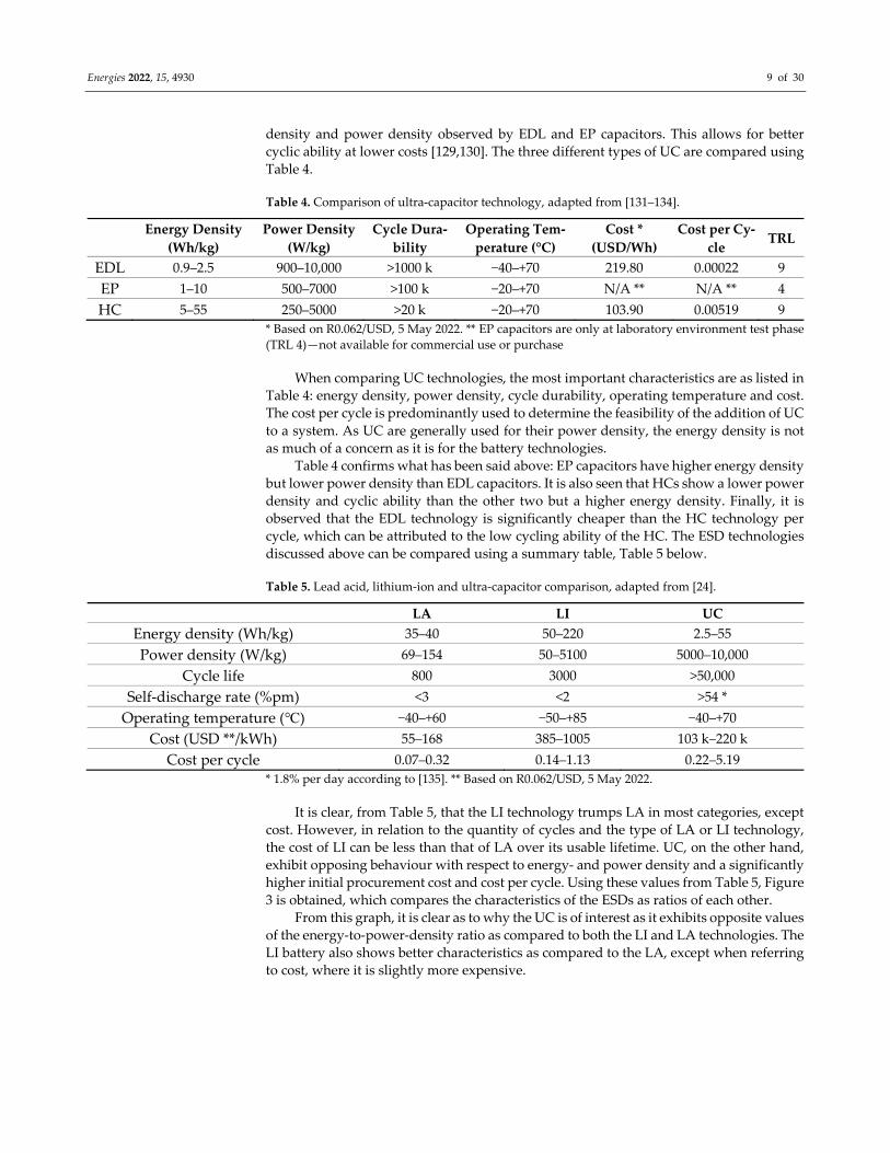
Energies 2022, 15, 4930 9 of 30
density and power density observed by EDL and EP capacitors. This allows for better
cyclic ability at lower costs [129,130]. The three different types of UC are compared using
Table 4.
Table 4. Comparison of ultra‐capacitor technology, adapted from [131–134].
Energy Density
(Wh/kg)
Power Density
(W/kg)
Cycle Dura‐
bility
Operating Tem‐
perature (°C)
Cost *
(USD/Wh)
Cost per Cy‐
cle TRL
EDL 0.9–2.5 900–10,000 >1000 k −40–+70 219.80 0.00022 9
EP 1–10 500–7000 >100 k −20–+70 N/A ** N/A ** 4
HC 5–55 250–5000 >20 k −20–+70 103.90 0.00519 9
* Based on R0.062/USD, 5 May 2022. ** EP capacitors are only at laboratory environment test phase
(TRL 4)—not available for commercial use or purchase
When comparing UC technologies, the most important characteristics are as listed in
Table 4: energy density, power density, cycle durability, operating temperature and cost.
The cost per cycle is predominantly used to determine the feasibility of the addition of UC
to a system. As UC are generally used for their power density, the energy density is not
as much of a concern as it is for the battery technologies.
Table 4 confirms what has been said above: EP capacitors have higher energy density
but lower power density than EDL capacitors. It is also seen that HCs show a lower power
density and cyclic ability than the other two but a higher energy density. Finally, it is
observed that the EDL technology is significantly cheaper than the HC technology per
cycle, which can be attributed to the low cycling ability of the HC. The ESD technologies
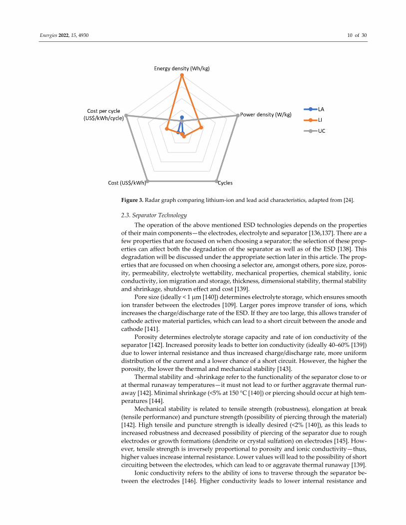
discussed above can be compared using a summary table, Table 5 below.
Table 5. Lead acid, lithium‐ion and ultra‐capacitor comparison, adapted from [24].
LA LI UC
Energy density (Wh/kg) 35–40 50–220 2.5–55
Power density (W/kg) 69–154 50–5100 5000–10,000
Cycle life 800 3000 >50,000
Self‐discharge rate (%pm) <3 <2 >54 *
Operating temperature (℃) −40–+60 −50–+85 −40–+70
Cost (USD **/kWh) 55–168 385–1005 103 k–220 k
Cost per cycle 0.07–0.32 0.14–1.13 0.22–5.19
* 1.8% per day according to [135]. ** Based on R0.062/USD, 5 May 2022.
It is clear, from Table 5, that the LI technology trumps LA in most categories, except
cost. However, in relation to the quantity of cycles and the type of LA or LI technology,
the cost of LI can be less than that of LA over its usable lifetime. UC, on the other hand,
exhibit opposing behaviour with respect to energy‐ and power density and a significantly
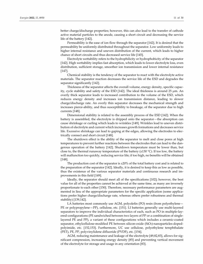
higher initial procurement cost and cost per cycle. Using these values from Table 5, Figure
3 is obtained, which compares the characteristics of the ESDs as ratios of each other.
From this graph, it is clear as to why the UC is of interest as it exhibits opposite values
of the energy‐to‐power‐density ratio as compared to both the LI and LA technologies. The
LI battery also shows better characteristics as compared to the LA, except when referring
to cost, where it is slightly more expensive.
Energies 2022, 15, 4930 10 of 30
Figure 3. Radar graph comparing lithium‐ion and lead acid characteristics, adapted from [24].
2.3. Separator Technology
The operation of the above mentioned ESD technologies depends on the properties
of their main components—the electrodes, electrolyte and separator [136,137]. There are a
few properties that are focused on when choosing a separator; the selection of these prop‐
erties can affect both the degradation of the separator as well as of the ESD [138]. This
degradation will be discussed under the appropriate section later in this article. The prop‐
erties that are focussed on when choosing a selector are, amongst others, pore size, poros‐
ity, permeability, electrolyte wettability, mechanical properties, chemical stability, ionic
conductivity, ion migration and storage, thickness, dimensional stability, thermal stability
and shrinkage, shutdown effect and cost [139].
Pore size (ideally < 1 μm [140]) determines electrolyte storage, which ensures smooth
ion transfer between the electrodes [109]. Larger pores improve transfer of ions, which
increases the charge/discharge rate of the ESD. If they are too large, this allows transfer of
cathode active material particles, which can lead to a short circuit between the anode and
cathode [141].
Porosity determines electrolyte storage capacity and rate of ion conductivity of the
separator [142]. Increased porosity leads to better ion conductivity (ideally 40–60% [139])
due to lower internal resistance and thus increased charge/discharge rate, more uniform
distribution of the current and a lower chance of a short circuit. However, the higher the
porosity, the lower the thermal and mechanical stability [143].
Thermal stability and ‐shrinkage refer to the functionality of the separator close to or
at thermal runaway temperatures—it must not lead to or further aggravate thermal run‐
away [142]. Minimal shrinkage (<5% at 150 °C [140]) or piercing should occur at high tem‐peratures [144].
Mechanical stability is related to tensile strength (robustness), elongation at break
(tensile performance) and puncture strength (possibility of piercing through the material)
[142]. High tensile and puncture strength is ideally desired (<2% [140]), as this leads to increased robustness and decreased possibility of piercing of the separator due to rough
electrodes or growth formations (dendrite or crystal sulfation) on electrodes [145]. How‐
ever, tensile strength is inversely proportional to porosity and ionic conductivity—thus,
higher values increase internal resistance. Lower values will lead to the possibility of short
circuiting between the electrodes, which can lead to or aggravate thermal runaway [139].
Ionic conductivity refers to the ability of ions to traverse through the separator be‐
tween the electrodes [146]. Higher conductivity leads to lower internal resistance and
Energies 2022, 15, 4930 11 of 30
better charge/discharge properties; however, this can also lead to the transfer of cathode
active material particles to the anode, causing a short circuit and decreasing the service
life of the battery [142].
Permeability is the ease of ion flow through the separator [142]. It is desired that the
permeability be uniformly distributed throughout the separator. Low uniformity leads to
higher internal resistance and uneven distribution of the current, which leads to higher
chance of short circuits and thus decreased service life [145].
Electrolyte wettability refers to the hydrophilicity or hydrophobicity of the separator
[142]. High wettability implies fast absorption, which leads to lower electrolyte loss, even
distribution, sufficient storage, smoother ion transmission and lower internal resistance
[147].
Chemical stability is the tendency of the separator to react with the electrolyte active
materials. The separator reaction decreases the service life of the ESD and degrades the
separator significantly [142].
Thickness of the separator affects the overall volume, energy density, specific capac‐
ity, cycle stability and safety of the ESD [142]. The ideal thickness is around 25 μm. An
overly thick separator leads to increased contribution to the volume of the ESD, which
reduces energy density and increases ion transmission distance, leading to slower
charge/discharge rate. An overly thin separator decreases the mechanical strength and
increases pierce‐ability, and thus susceptibility to breakage, of the separator due to high
currents [148].
Dimensional stability is related to the assembly process of the ESD [142]. When the
battery is assembled, the electrolyte is dripped onto the separator—the absorption can
cause shrinkage or curling which leads to wrinkles [149]. Wrinkles lead to uneven distri‐
bution of electrolyte and current which increases growth formations and decreases service
life. Excessive shrinkage can lead to gaping at the edges, allowing the electrodes to elec‐
trically connect and short circuit [148].
The shutdown effect is the ability of the separator to melt and close pores at high
temperatures to prevent further reactions between the electrodes that can lead to the dan‐
gerous operation of the battery [142]. Shutdown temperature must be lower than, but
close to, the thermal runaway temperature of the battery (±130 °C). If too low, the battery
will malfunction too quickly, reducing service life; if too high, no benefits will be obtained
[148].
The production cost of the separator is ±20% of the total battery cost and is related to
the preparation of the separator [142]. Ideally, it is desired to keep this as low as possible,
thus the existence of the various separator materials and continuous research and im‐
provements in this field [149].
Ideally, the separator should meet all of the specifications [102]; however, the best
value for all of the properties cannot be achieved at the same time, as many are inversely
proportionate to each other [150]. Therefore, necessary performance parameters are aug‐
mented in lieu of the appropriate parameters for the specific application (some applica‐
tions prefer higher charge/discharge rate, whereas others prefer robustness and thermal
stability) [139,142].
LA batteries most commonly use AGM, polyolefin (PO) resin (from polyethylene—
PE or polypropylene—PP), cellulose, etc. [151]. LI batteries generally use multi‐layered
separators to improve the individual characteristics of each, such as PO in multiple‐lay‐
ered‐configurations (PE sandwiched between two layers of PP or a combination of single‐
layered PE and PP), a variant of these configurations which includes a ceramic‐coated
separator, ethylcellulose‐modified PE between silicon‐oxide (SiO2)‐nanoparticles‐doped‐
polyimide, etc. [152,153]. Furthermore, UC use cellulose, polyethylene terephthalate
(PET), PE, PP, polyvinylidene difluoride (PVDF), etc. [154].
AGM, reducing maintenance and leakage of the electrolyte [49,82,83], allows for sig‐
nificant compression, increasing energy density [85] and preventing vertical movement
of the electrolyte for storage and usage in any orientation [83].
Energies 2022, 15, 4930 12 of 30
PO is derived from PP, PE or a lamination of the two [155,156]. They are the most
commercially used separators due to the low production cost, higher mechanical strength
and electrochemical stability [109], but they have low electrolyte absorption, are hydro‐
phobic, have poor wettability, low porosity, poor thermal stability and a low thermal de‐
formation temperature (80–85 °C and 100 °C, respectively), leading to thermal shrinkage
and short circuits [157–159]—all of these decrease battery cycle life [139]. They are usually
used in a PE/PP or PP/PE/PP configuration due to their individual characteristics; PE has
good flexibility but a low melting point (130 °C), whereas PP has good mechanical prop‐
erties and a high melting point (165 °C) [139,160]. The combination of the two therefore
leads to low closed cell temperature and high fusing temperature, improved cyclability
and safety performance of the battery [102].
Multi‐layer variations improve stability and safety [161], and the addition of a ce‐
ramic‐coated separator improves on the thermal stability [152]. The ethylcellulose varia‐
tion is used in high performance batteries that accommodate both thermal runaway at
high temperatures and thermal shutdown at low temperatures [139].
Cellulose, a constituent of plants and microorganisms [103,104] has better electrolyte
uptake, interface stability and enhanced ionic conductivity [142,162], as compared to PP.
It can improve the rate capability [163], cycling retention and thermal dimensional stabil‐
ity of the ESD [164]. Cellulose shows good flame retardancy, superior heat tolerance and
proper mechanical strength [165].
PET has excellent mechanical, thermodynamic and electrical insulation properties,
with the best form of this product being one with composite film with ceramic particles
coated on the PET membrane. It shows excellent heat resistance with a high closed cell
temperature of 220 °C [113].
Compared to PO, PVDF‐based separators are characterized by strong polarity, high
dielectric constant, stable electrochemical performance, excellent tensile properties and
mechanical strength and favourable thermal stability and wettability [114–116]. They are
also hydrophilic [166,167]. According to R. Liu et al. [114], PVDF has better porosity, elec‐
trolyte wettability, ionic conductivity and thermal stability as compared to PO, with sim‐
ilar chemical stability [107–112].
Separator engineering presents a formidable strategy in the improvement of battery
and UC operation, specifically in suppressing growth formations [140]. Advances in sep‐
arator technology have found that traditional PO separators are mechanically insufficient
and thermally unstable, whilst multi‐layer and ceramic coated self‐shutdown separators
show promise in their partial improvement of mechanical and thermal stability [152]. Ta‐
bles 5 and 6 in B. Boateng et al. [140] present three techniques that show improvement of
the downfalls of the current/most commonly used separator technologies and the perfor‐
mance that each obtains. Surface modification (employing various surface coating meth‐
ods); single‐layer (blending/doping of polymer substrates); and multi‐layer (layering of
substrates) are discussed, which all lead to improved performance and decreased growth
formations. A. Heidari et al. [168] presents a discussion of surface modifications based on
grafting methods, a mussel‐inspired technique and functionalization by inorganic
nanostructures that show promising improvements to the operation of ESDs. These meth‐
ods also present a reduction in growth formations. J. Li et al. [169] presents the use of free‐
standing cellulose nanofiber to reduce polysulfide shuttle effect and dendrite growth,
which results in an increase in discharge capacity. S. Thiangtham et al. [170] presents the
use of bio‐membranes based on a sulfonated cellulose blend that provides a variety of
characteristic improvements, such as better ionic conductivity, higher discharge rate and
better capacity retention whilst increasing porosity.
These mentioned case studies show that, although some of the separators have infe‐
rior performance characteristics, they can still have relevance through various construc‐
tion techniques or combinations with other substrates. This alludes to the significance of
the study into separator technologies and their degradation contribution with various
ESD applications.
Energies 2022, 15, 4930 13 of 30
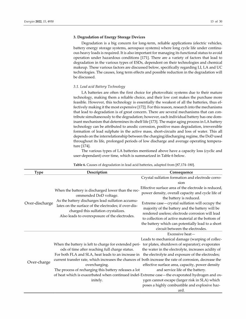
3. Degradation of Energy Storage Devices
Degradation is a big concern for long‐term, reliable applications (electric vehicles,
battery energy storage systems, aerospace systems) where long cycle life under continu‐
ous heavy loads is required. It is also important for managing its functional status to avoid
operation under hazardous conditions [171]. There are a variety of factors that lead to
degradation in the various types of ESDs, dependent on their technologies and chemical
makeup. These various factors are discussed below, specifically regarding LI, LA and UC
technologies. The causes, long term effects and possible reduction in the degradation will
be discussed.
3.1. Lead acid Battery Technology
LA batteries are often the first choice for photovoltaic systems due to their mature
technology, making them a reliable choice, and their low cost makes the purchase more
feasible. However, this technology is essentially the weakest of all the batteries, thus ef‐
fectively making it the most expensive [172]. For this reason, research into the mechanisms
that lead to degradation is of great concern. There are several mechanisms that can con‐
tribute simultaneously to the degradation; however, each individual battery has one dom‐
inant mechanism that determines its shelf life [173]. The major aging process in LA battery
technology can be attributed to anodic corrosion, positive mass degradation, irreversible
formation of lead sulphate in the active mass, short‐circuits and loss of water. This all
depends on the interrelationship between the charging/discharging regime, the DoD used
throughout its life, prolonged periods of low discharge and average operating tempera‐
ture [174].
The various types of LA batteries mentioned above have a capacity loss (cyclic and
user‐dependant) over time, which is summarized in Table 6 below.
Table 6. Causes of degradation in lead acid batteries, adapted from [87,174–180].
Type Description Consequence
Over‐discharge
When the battery is discharged lower than the rec‐
ommended DoD voltage.
As the battery discharges lead sulfation accumu‐
lates on the surface of the electrodes; if over‐dis‐
charged this sulfation crystalizes.
Also leads to overexposure of the electrodes.
Crystal sulfation formation and electrode corro‐
sion
Effective surface area of the electrode is reduced,
power density, overall capacity and cycle life of
the battery is reduced.
Extreme case—crystal sulfation will occupy the
majority of the battery and the battery will be
rendered useless; electrode corrosion will lead
to collection of active material at the bottom of
the battery which can potentially lead to a short
circuit between the electrodes.
Over‐charge
When the battery is left to charge for extended peri‐
ods of time after reaching full charge status.
For both FLA and SLA, heat leads to an increase in
current transfer rate, which increases the chances of
overcharging.
The process of recharging this battery releases a lot
of heat which is exacerbated when continued indef‐
initely.
Excessive heat—
Leads to mechanical damage (warping of collec‐
tor plates, shutdown of separator); evaporates
the water in the electrolyte, increases acidity of
the electrolyte and exposure of the electrodes;
both increase the rate of corrosion, decrease the
effective surface area, capacity, power density
and service life of the battery.
Extreme case—the evaporated hydrogen and ox‐
ygen cannot escape (larger risk in SLA) which
poses a highly combustible and explosive haz‐
ard.
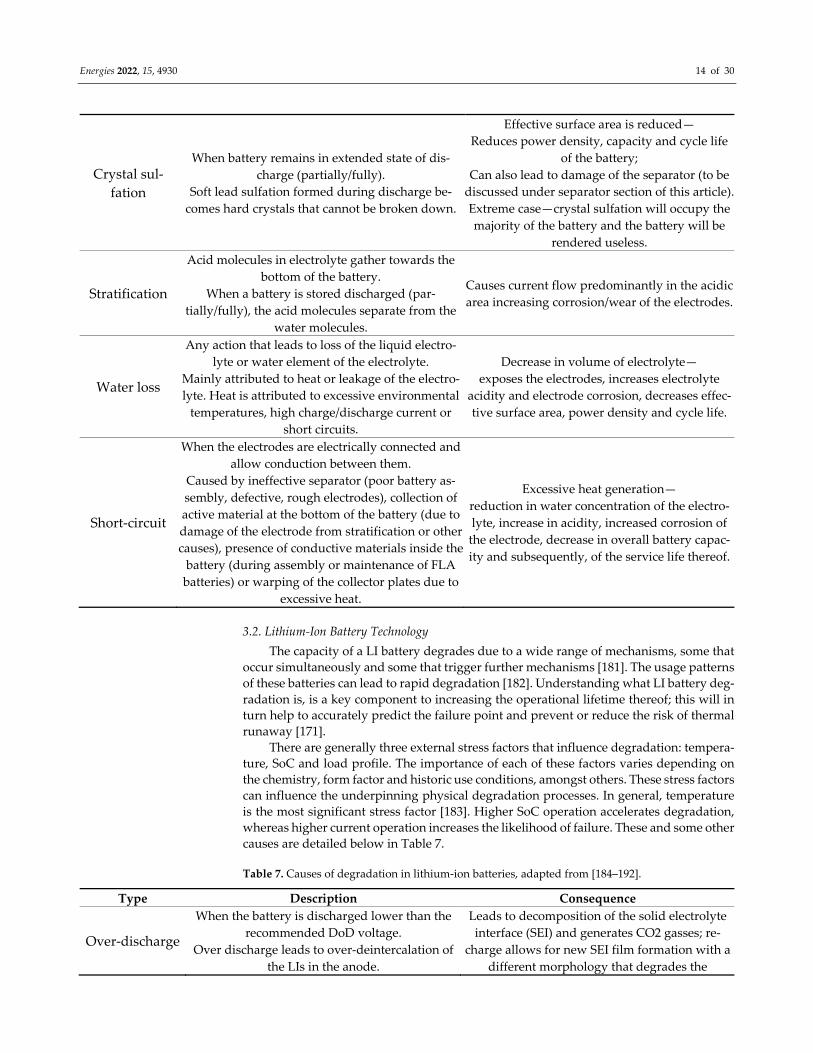
Energies 2022, 15, 4930 14 of 30
Crystal sul‐
fation
When battery remains in extended state of dis‐
charge (partially/fully).
Soft lead sulfation formed during discharge be‐
comes hard crystals that cannot be broken down.
Effective surface area is reduced—
Reduces power density, capacity and cycle life
of the battery;
Can also lead to damage of the separator (to be
discussed under separator section of this article).
Extreme case—crystal sulfation will occupy the
majority of the battery and the battery will be
rendered useless.
Stratification
Acid molecules in electrolyte gather towards the
bottom of the battery.
When a battery is stored discharged (par‐
tially/fully), the acid molecules separate from the
water molecules.
Causes current flow predominantly in the acidic
area increasing corrosion/wear of the electrodes.
Water loss
Any action that leads to loss of the liquid electro‐
lyte or water element of the electrolyte.
Mainly attributed to heat or leakage of the electro‐
lyte. Heat is attributed to excessive environmental
temperatures, high charge/discharge current or
short circuits.
Decrease in volume of electrolyte—
exposes the electrodes, increases electrolyte
acidity and electrode corrosion, decreases effec‐
tive surface area, power density and cycle life.
Short‐circuit
When the electrodes are electrically connected and
allow conduction between them.
Caused by ineffective separator (poor battery as‐
sembly, defective, rough electrodes), collection of
active material at the bottom of the battery (due to
damage of the electrode from stratification or other
causes), presence of conductive materials inside the
battery (during assembly or maintenance of FLA
batteries) or warping of the collector plates due to
excessive heat.
Excessive heat generation—
reduction in water concentration of the electro‐
lyte, increase in acidity, increased corrosion of
the electrode, decrease in overall battery capac‐
ity and subsequently, of the service life thereof.
3.2. Lithium‐Ion Battery Technology
The capacity of a LI battery degrades due to a wide range of mechanisms, some that
occur simultaneously and some that trigger further mechanisms [181]. The usage patterns
of these batteries can lead to rapid degradation [182]. Understanding what LI battery deg‐
radation is, is a key component to increasing the operational lifetime thereof; this will in
turn help to accurately predict the failure point and prevent or reduce the risk of thermal
runaway [171].
There are generally three external stress factors that influence degradation: tempera‐
ture, SoC and load profile. The importance of each of these factors varies depending on
the chemistry, form factor and historic use conditions, amongst others. These stress factors
can influence the underpinning physical degradation processes. In general, temperature
is the most significant stress factor [183]. Higher SoC operation accelerates degradation,
whereas higher current operation increases the likelihood of failure. These and some other
causes are detailed below in Table 7.
Table 7. Causes of degradation in lithium‐ion batteries, adapted from [184–192].
Type Description Consequence
Over‐discharge
When the battery is discharged lower than the
recommended DoD voltage.
Over discharge leads to over‐deintercalation of
the LIs in the anode.
Leads to decomposition of the solid electrolyte
interface (SEI) and generates CO2 gasses; re‐
charge allows for new SEI film formation with a
different morphology that degrades the
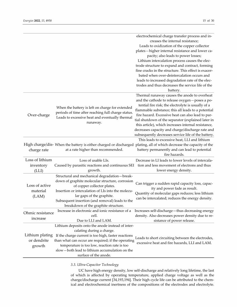
Energies 2022, 15, 4930 15 of 30
electrochemical charge transfer process and in‐
creases the internal resistance;
Leads to oxidization of the copper collector
plates—higher internal resistance and lower ca‐
pacity; also leads to power losses;
Lithium intercalation process causes the elec‐
trode structure to expand and contract, forming
fine cracks in the structure. This effect is exacer‐
bated when over‐deintercalation occurs and
leads to increased degradation rate of the elec‐
trodes and thus decreases the service life of the
battery.
Over‐charge
When the battery is left on charge for extended
periods of time after reaching full charge status.
Leads to excessive heat and eventually thermal
runaway.
Thermal runaway causes the anode to overheat
and the cathode to release oxygen—poses a po‐
tential fire risk; the electrolyte is usually of a
flammable substance; this all leads to a potential
fire hazard. Excessive heat can also lead to par‐
tial shutdown of the separator (explained later in
this article), which increases internal resistance,
decreases capacity and charge/discharge rate and
subsequently decreases service life of the battery.
High charge/dis‐
charge rate
When the battery is either charged or discharged
at a rate higher than recommended.
This leads to excessive heat, LLI and lithium
plating, all of which decrease the capacity of the
battery permanently and can lead to potential
fire hazards.
Loss of lithium
inventory
(LLI)
Loss of usable LIs.
Caused by parasitic reactions and continuous SEI
growth.
Decrease in LI leads to lower levels of intercala‐
tion and less movement of electrons and thus
lower energy density.
Loss of active
material
(LAM)
Structural and mechanical degradation—break‐
down of graphite molecular structure, corrosion
of copper collector plates.
Insertion or intercalation of LIs into the molecu‐
lar gaps of the graphite.
Subsequent insertion (and removal) leads to the
breakdown of the graphite structure.
Can trigger a sudden rapid capacity loss, capac‐
ity and power fade as result.
Quantity of molecular gaps reduces; less lithium
can be intercalated; reduces the energy density.
Ohmic resistance
increase
Increase in electronic and ionic resistance of a
cell.
Due to LLI and LAM.
Increases self‐discharge—thus decreasing energy
density. Also decreases power density due to re‐
sistance of power release.
Lithium plating
or dendrite
growth
Lithium deposits onto the anode instead of inter‐
calating during a charge.
If the charge current is too high, faster reactions
than what can occur are required; if the operating
temperature is too low, reaction rate is too
slow—both lead to lithium accumulation on the
surface of the anode.
Leads to short circuiting between the electrodes,
excessive heat and fire hazards, LLI and LAM.
3.3. Ultra‐Capacitor Technology
UC have high energy density, low self‐discharge and relatively long lifetime, the last
of which is affected by operating temperature, applied charge voltage as well as the
charge/discharge current [34,193,194]. Their high cycle life can be attributed to the chem‐
ical and electrochemical inertness of the compositions of the electrodes and electrolyte.
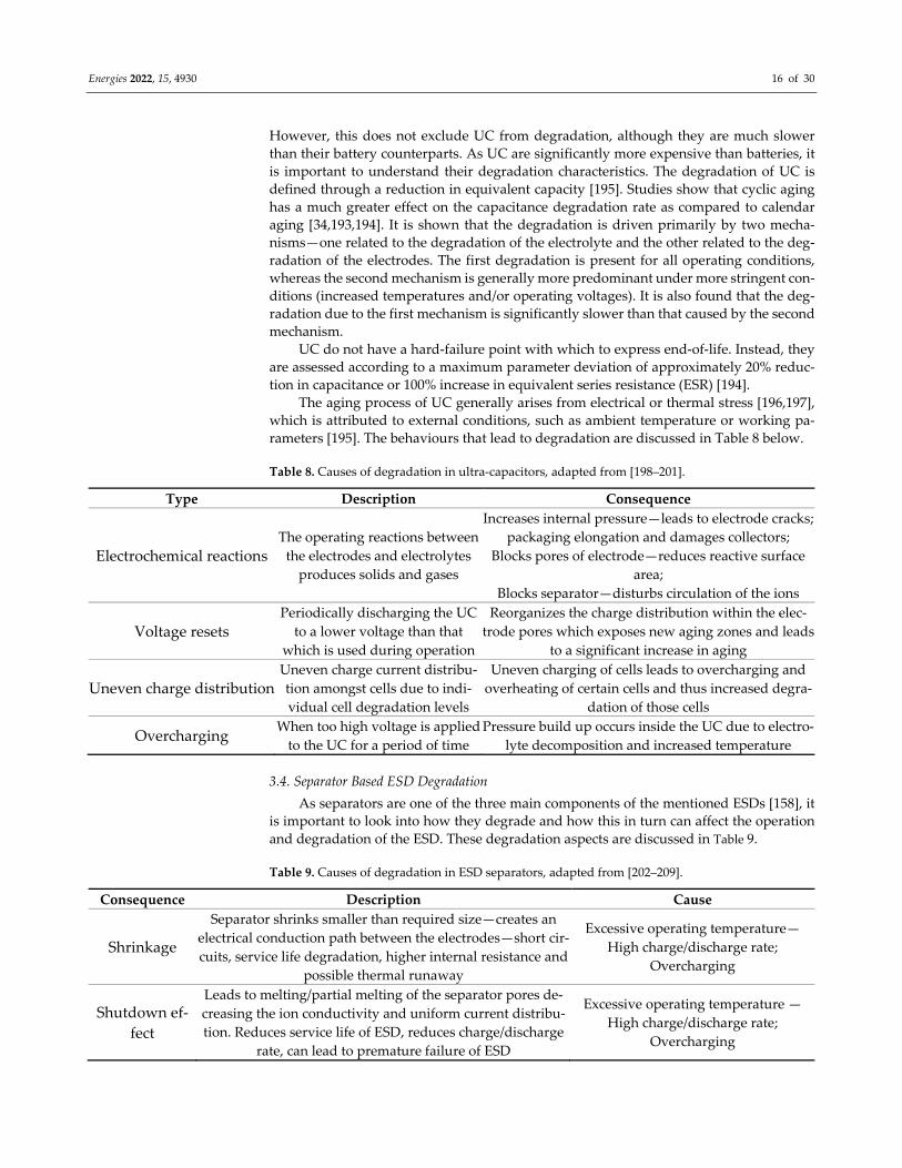
Energies 2022, 15, 4930 16 of 30
However, this does not exclude UC from degradation, although they are much slower
than their battery counterparts. As UC are significantly more expensive than batteries, it
is important to understand their degradation characteristics. The degradation of UC is
defined through a reduction in equivalent capacity [195]. Studies show that cyclic aging
has a much greater effect on the capacitance degradation rate as compared to calendar
aging [34,193,194]. It is shown that the degradation is driven primarily by two mecha‐
nisms—one related to the degradation of the electrolyte and the other related to the deg‐
radation of the electrodes. The first degradation is present for all operating conditions,
whereas the second mechanism is generally more predominant under more stringent con‐
ditions (increased temperatures and/or operating voltages). It is also found that the deg‐
radation due to the first mechanism is significantly slower than that caused by the second
mechanism.
UC do not have a hard‐failure point with which to express end‐of‐life. Instead, they
are assessed according to a maximum parameter deviation of approximately 20% reduc‐
tion in capacitance or 100% increase in equivalent series resistance (ESR) [194].
The aging process of UC generally arises from electrical or thermal stress [196,197],
which is attributed to external conditions, such as ambient temperature or working pa‐
rameters [195]. The behaviours that lead to degradation are discussed in Table 8 below.
Table 8. Causes of degradation in ultra‐capacitors, adapted from [198–201].
Type Description Consequence
Electrochemical reactions The operating reactions between
the electrodes and electrolytes
produces solids and gases
Increases internal pressure—leads to electrode cracks;
packaging elongation and damages collectors;
Blocks pores of electrode—reduces reactive surface
area;
Blocks separator—disturbs circulation of the ions
Voltage resets Periodically discharging the UC
to a lower voltage than that
which is used during operation
Reorganizes the charge distribution within the elec‐
trode pores which exposes new aging zones and leads
to a significant increase in aging
Uneven charge distribution Uneven charge current distribu‐
tion amongst cells due to indi‐
vidual cell degradation levels
Uneven charging of cells leads to overcharging and
overheating of certain cells and thus increased degra‐
dation of those cells
Overcharging When too high voltage is applied
to the UC for a period of time
Pressure build up occurs inside the UC due to electro‐
lyte decomposition and increased temperature
3.4. Separator Based ESD Degradation
As separators are one of the three main components of the mentioned ESDs [158], it
is important to look into how they degrade and how this in turn can affect the operation
and degradation of the ESD. These degradation aspects are discussed in Table 9.
Table 9. Causes of degradation in ESD separators, adapted from [202–209].
Consequence Description Cause
Shrinkage
Separator shrinks smaller than required size—creates an
electrical conduction path between the electrodes—short cir‐
cuits, service life degradation, higher internal resistance and
possible thermal runaway
Excessive operating temperature—
High charge/discharge rate;
Overcharging
Shutdown ef‐
fect
Leads to melting/partial melting of the separator pores de‐
creasing the ion conductivity and uniform current distribu‐
tion. Reduces service life of ESD, reduces charge/discharge
rate, can lead to premature failure of ESD
Excessive operating temperature —
High charge/discharge rate;
Overcharging
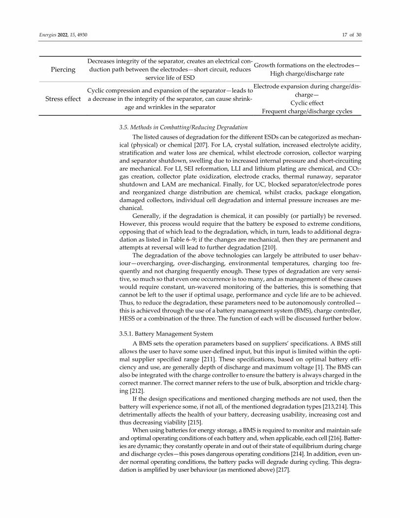
Energies 2022, 15, 4930 17 of 30
Piercing Decreases integrity of the separator, creates an electrical con‐
duction path between the electrodes—short circuit, reduces
service life of ESD
Growth formations on the electrodes—
High charge/discharge rate
Stress effect Cyclic compression and expansion of the separator—leads to
a decrease in the integrity of the separator, can cause shrink‐
age and wrinkles in the separator
Electrode expansion during charge/dis‐
charge—
Cyclic effect
Frequent charge/discharge cycles
3.5. Methods in Combatting/Reducing Degradation
The listed causes of degradation for the different ESDs can be categorized as mechan‐
ical (physical) or chemical [207]. For LA, crystal sulfation, increased electrolyte acidity,
stratification and water loss are chemical, whilst electrode corrosion, collector warping
and separator shutdown, swelling due to increased internal pressure and short‐circuiting
are mechanical. For LI, SEI reformation, LLI and lithium plating are chemical, and CO2‐
gas creation, collector plate oxidization, electrode cracks, thermal runaway, separator
shutdown and LAM are mechanical. Finally, for UC, blocked separator/electrode pores
and reorganized charge distribution are chemical, whilst cracks, package elongation,
damaged collectors, individual cell degradation and internal pressure increases are me‐
chanical.
Generally, if the degradation is chemical, it can possibly (or partially) be reversed.
However, this process would require that the battery be exposed to extreme conditions,
opposing that of which lead to the degradation, which, in turn, leads to additional degra‐
dation as listed in Table 6–9; if the changes are mechanical, then they are permanent and
attempts at reversal will lead to further degradation [210].
The degradation of the above technologies can largely be attributed to user behav‐
iour—overcharging, over‐discharging, environmental temperatures, charging too fre‐
quently and not charging frequently enough. These types of degradation are very sensi‐
tive, so much so that even one occurrence is too many, and as management of these causes
would require constant, un‐wavered monitoring of the batteries, this is something that
cannot be left to the user if optimal usage, performance and cycle life are to be achieved.
Thus, to reduce the degradation, these parameters need to be autonomously controlled—
this is achieved through the use of a battery management system (BMS), charge controller,
HESS or a combination of the three. The function of each will be discussed further below.
3.5.1. Battery Management System
A BMS sets the operation parameters based on suppliers’ specifications. A BMS still
allows the user to have some user‐defined input, but this input is limited within the opti‐
mal supplier specified range [211]. These specifications, based on optimal battery effi‐
ciency and use, are generally depth of discharge and maximum voltage [1]. The BMS can
also be integrated with the charge controller to ensure the battery is always charged in the
correct manner. The correct manner refers to the use of bulk, absorption and trickle charg‐
ing [212].
If the design specifications and mentioned charging methods are not used, then the
battery will experience some, if not all, of the mentioned degradation types [213,214]. This
detrimentally affects the health of your battery, decreasing usability, increasing cost and
thus decreasing viability [215].
When using batteries for energy storage, a BMS is required to monitor and maintain safe
and optimal operating conditions of each battery and, when applicable, each cell [216]. Batter‐
ies are dynamic; they constantly operate in and out of their state of equilibrium during charge
and discharge cycles—this poses dangerous operating conditions [214]. In addition, even un‐
der normal operating conditions, the battery packs will degrade during cycling. This degra‐
dation is amplified by user behaviour (as mentioned above) [217].

Energies 2022, 15, 4930 18 of 30
The goals of a BMS thus include: matching peak power demands, following the load,
reducing intermittency, protecting the cells from internal degradation and capacity fade,
providing optimal charging patterns, balancing the cells in a battery pack, etc. [1]. The
most basic of these goals is to balance state of charge (SoC) across the cells of the battery
pack, for this there are three categories: centralized—a single controller with multiple
wires connected to the various cells; distributed—a BMS board on each cell with a com‐
munication cable between the battery and controller; modular—a few controllers, each
controlling a few cells where the controllers communicate with each other. Centralized is
economical but least expandable and messy (in terms of the wires); distributed are the
most expensive but they are the simplest to implement and the cleanest; modular is a
combination of the other two [218].
LA batteries do not have separate cell indicators or measurements—they do not re‐
quire cell balancing—thus, this aspect of a BMS is lost here [219]. LI technologies, on the
other hand, require cell balancing and thermal monitoring of these cells specifically, thus
proving the usefulness of this aspect of BMSs. The BMS is therefore primarily used to
reduce/prevent unnecessary degradation due to user behaviour (overcharge, under‐
charge, over‐discharge, incorrect charge patterns, etc.) and monitor safety aspects (ther‐
mal runaway) [220]. One other very important role of BMSs is to control the charge pro‐
cess; this is discussed later.
3.5.2. Charge Controller
A charge controller regulates the current flowing from the power source into the bat‐
tery bank to avoid overcharging the batteries [83,221]. There are two variations of charge
controllers: pulse width modulation (PWM) and maximum power point tracking (MPPT)
[222,223]. PWM accepts the power that is available from the source and adjusts the voltage
according to what the battery requires. The battery will only receive the maximum current
that the source is rated to supply [224]. As the battery charges, the required voltage will
increase and resultantly increase the power used from the source. However, the maximum
power of the source will only be utilized if the battery requires a voltage that matches the
maximum voltage supply of the source [225]. MPPT acts as a buffer and uses the voltage
required by the source to determine the current used according to the maximum power
available. Therefore, MPPT will always supply the maximum power available [226].
3.5.3. Hybrid Energy Storage System
Due to the properties of batteries, higher energy density vs. power density, weight,
slower recharge, etc., it is very beneficial to combine various energy sources to obtain the
best of both (or multiple) worlds from their various properties. By combining multiple
energy sources, it is also possible to reduce the accumulative degradation (the usage of
each source is reduced per use) [227].
In order to combine energy sources to gain these benefits, careful consideration needs
to be taken regarding the energy management of the system—in other words, when to use
which source [228]. It is important to control when each source is used, and for what pur‐
pose, such that the benefits can actually be achieved and optimized [229]. This can be con‐
trolled in a multitude of strategies, known as an energy management strategy (EMS). An
EMS is a set of processes that monitor, control and optimize the performance of an energy
system [230]. This is mainly achieved through the allocation of the HESS [231]. A basic
strategy is achieved through topological control (a strategy referring to the placement of
the sources with respect to the load [232])—this can include bi‐directional or uni‐direc‐
tional flow of current.
From previous experimentation, A. Townsend et al. [232], the order of the connec‐
tions can have an effect on the usage of the sources. In the case study, experimentation
combined two sources to provide a load using a topological EMS. One test placed both
sources before the load and another placed the load between the sources [232]. This strat‐
egy does not require any electronic control or switching between the sources, is a very
Energies 2022, 15, 4930 19 of 30
basic EMS and provides a benefit of a less complex, smaller sized and lighter system but
does not deliver the most optimal HESS [232].
The main objective of an EMS is to coordinate the power allocation of the independ‐
ent sources of the HESS [233]. This is generally divided into two categories: rule‐based
and optimization‐based [216]. Both methods create a set of rules and a set of HESS states—
the states determine which source is in use and the rules determine which state the HESS
should be in. The rules for each state are determined by completed experimentation; they
do not vary after implementation. For the rule‐based strategy, instantaneous measure‐
ments, of the source and load, are used to comply with the rules and determine the HESS
state [234,235].
The optimization‐based EMS predicts the requirements of the load and adjusts the
HESS state according to this prediction. These predictions are based on continued use of
the implemented system, thus optimizing through use [236–238]. This method can further
be divided into online and offline methods [239]—the latter will develop its own database
of information from its own use; online methods use information gathered from a global
network containing collections of applications of the implemented system or those similar
to it. Online requires a method of connecting to this global platform (cloud), whereas of‐
fline requires a large internal memory for continued storage of data. The predictions of
this method are continually improved throughout use of the system, thus continuously
optimizing the system [229,236,240].
SM. Lukie et al. [241] uses an integrated rule‐based meta‐heuristic optimization ap‐
proach for a multi‐level EMS of a multi‐source EV. A heuristic technique refers to a partial
search algorithm, whereas a meta‐heuristic technique is more or less accurate solution—
it makes certain assumptions initially, which are either local or random. The meta‐heuris‐
tic technique is used to optimize the split without prior knowledge of the power de‐
mand—it makes assumptions according to a local or random online search. For this
method, the search space is limited according to pre‐set rules and the meta‐heuristic tech‐
nique requires making a few assumptions. Although the latter point allows the approach
to find good solutions over a larger search space with less computational effort than other
more precise efforts, it still requires these assumptions, thus leading to a solution whose
accuracy is dependent on those initial assumptions.
Z. Y. Chen et al. [242] uses a fuzzy logic, rule‐based control strategy for a parallel
HEV. This EMS uses the initial capacity of the battery and does not take into account the
depletion and degradation due to its use.
C. G. Hochgraf et al. [243] uses a flatness control technique (FCT) and fuzzy logic
control (FLC) for the EMS. This technique uses a single, general control algorithm in dif‐
ferent operating modes, to avoid commutation, and no predictions of system behaviour
are made. Once again, the depletion and degradation of the capacity of the battery is not
taken into account for this EMS.
H. M. Liu et al. [244] uses a multiple for‐loop structure with a pre‐set cost function to
globally calculate the best EMS. A three‐mode rule‐based strategy is used to minimize the
total consumed energy. This method requires that a pre‐set cost function be used, and pre‐
set rules are used to determine the states of the HESS. These rules are static and do not
vary throughout use of the HESS.
J. Cao et al. [245] uses an optimization‐based HESS for an electric bus. This EMS uti‐
lises FLC, MPC, rule‐based controller (RBC) and filtration‐based controller (FBC). FLC
uses pre‐set rules that do not vary throughout the use of the EMS, MPC predicts future
trends of use, RBC uses pre‐set rules and FBC requires estimates of use—all four of the
methods are based on the initial capacities of the source.
H. L. Yu et al. [246] utilizes ESDs of which the current and SOC are maintained within
pre‐defined limits during operation. The EMS utilizes an MPC and predicts the duty cycle
value required for the DC‐DC controllers of the battery and capacitor, such that the pro‐
vided current will equal the required current. This is based on the SOC, voltage and
Energies 2022, 15, 4930 20 of 30
current of the hybrid sources. This optimization‐based method predicts the duty cycle
requirements based on the initial capacities (SOC range, voltage and current) of the
sources.
A. Burke et al. [247] uses an offline optimization‐based HESS. This system utilizes
MPC and rule‐based strategy. A period of future velocity is predicted, and an algorithm
is applied to optimize the control strategy accordingly. These velocity predictions are ac‐
cording to the data accumulated for the HESS by the HESS.
J. Y. Shen et al. [248] compares generalized exponentially varying (GEV), artificial
neural network (ANN) (time‐series forecasting and Markov chain models) and vehicular
velocity modelling, when used in an HESS. GEV predicts future velocities. This prediction
requires an initial velocity, time‐step and exponential coefficient. ANN is accurate in pre‐
dicting non‐linear dynamic behaviour. It can be trained to learn a highly non‐linear in‐
put/output relationship.
A Markov chain model is accurate for predicted fixed route driving patterns; this is
not so much the case with comprehensive driving tasks. Prediction relies on the present
state and historical values—the more historical the data the more accurate the prediction.
The Markov chain complexity can be increased if more conditions are included, which
will resultantly improve accuracy; however, complexity requires more historical data and
for the chains to cover all possible input states.
In J. Shen et al. [229], a multi‐objective problem is formulated to optimize the power
split. This EMS uses dynamic programming, and a neural network (NN) does the power
split. This is an online EMS thus requiring the collection of previously obtained results in
similar applications.
4. Conclusions
Comparing the various degradation causes for the mentioned ESDs, a few common‐
alities can be obtained. Over‐discharging, over‐charging and increased internal resistance
(IR) are the three most common causes amongst the ESDs, the first of which is more spe‐
cific for BESS and not so much for UC. Increases in IR are generally due to all the other
causes—electrolyte and active material ionic mobility, separator efficiency, concentration
polarisation and temperatures [249]—as the ESD degrades the internal resistance in‐
creases, reducing the ability of the ESDs to supply the specified capacity and thus reduc‐
ing the overall capacity of the ESDs [250].
All of the EMSs discussed in Section 3.5.3 have a pre‐determined set switching
point—the rules used to determine when, and how, each source is used—that does not
vary throughout use of the system. These rules are generally made according to the range
of the source and the current requirements of the load. The range of the source(s) is deter‐
mined by the pre‐defined and initial SOC, DoD, energy density and power density rat‐
ings. All of these ratings change during each use and throughout the sources’ lifetime—
these changes are not included in the initial design, or continued optimization, of the sys‐
tem [142].
All of these systems and methods are aimed at reducing the effects and causes of the
mentioned degradation; none look into adjusting use dynamically to reduce further deg‐
radation. For example, it is a well‐known fact that the capacity drops as the used cycles
increase, but the battery is still utilised within the original full‐health parameters.
A basic BMS will control only the battery packs to meet the load requirements; when
intelligent control is integrated, BMSs can reduce the causes of degradation, providing
more optimal performance and cycle life. There exist many different variations of BMSs
and intricate control algorithms that help prevent or reduce the behaviours that can accel‐
erate degradation of the battery. Herein lies the dilemma—these systems are designed to
reduce the cause of degradation through better utilization of the battery. However, one
largely overlooked factor is that the battery continues to be used according to its original
“full‐health” specifications. Figure 3 of P. Zhang et al. [8] and Figure 11 of V. Sedlakova et
al. [9] illustrate the well‐known fact that battery capacity decreases as more cycles are
Energies 2022, 15, 4930 21 of 30
utilized—the degradation being discussed—yet the battery is still used according to the
original capacity.
If discharge capacity is decreasing, essentially C‐rate should be adjusted, accord‐
ingly; the maximum voltage drops. Thus, this value should be adjusted to avoid over‐
charging as charging range has dropped; essentially power density is also decreasing and
therefore the surge values should be reduced. As the cycles of the battery are the optimal
range within which the battery should charge and discharge to achieve the best longevity
from the capacity, if the battery maximum voltage drops, then essentially only a portion
of the cycle will be used (if an adjustment is made to this parameter in the BMS). This
dynamic adjustment or alteration can lead to two results: an improvement in cycle life
and a reduction in overcharge degradation.
Battery and UC degradation is a given; regardless of how well it is used, it will de‐
grade. Thus, the proposal is to measure the degradation, dynamically and continuously,
and include it in the parameters of the BMS and charge controller. Previous studies look
into methods of reducing the causes of degradation, but there are few studies that look
into the increase in said degradation when battery use is continued according to its initial
“full health” parameters, or the adjustment of the parameters as the battery degrades.
Author Contributions: Conceptualization and writing, original draft preparation, editing, A.T.;
Conceptualization, review, editing, supervision, R.G. All authors have read and agreed to the pub‐
lished version of the manuscript.
Funding: This research received no external funding.
Institutional Review Board Statement: Not applicable.
Informed Consent Statement: Not applicable.
Data Availability Statement: Not applicable.
Conflicts of Interest: The authors declare no conflict of interest.
References
1. Lawder, M.T.; Suthar, B.; Northrop, P.W.C.; De, S.; Hoff, C.M.; Leitermann, O.; Crow, M.L.; Santhanagopalan, S.; Subramanian,
V.R. Battery Energy Storage System (BESS) and Battery Management System (BMS) for Grid‐Scale Applications. Proc. IEEE
2014, 102, 1014–1030. https://doi.org/10.1109/JPROC.2014.2317451.
2. Cagnano, A.; De Tuglie, E.; Gibilisco, P. Assessment and Control of Microgrid Impacts on Distribution Networks by Using
Experimental Tests. IEEE Trans. Ind. Appl. 2019, 55, 7157–7164. https://doi.org/10.1109/TIA.2019.2940174.
3. Sarbu, I.; Sebarchievici, C. A Comprehensive Review of Thermal Energy Storage. Sustainability 2018, 10, 191.
https://doi.org/10.3390/su10010191.
4. Ball, M.; Weeda, M. The Hydrogen Economy—Vision or Reality? In Compendium of Hydrogen Energy; Elsevier: Amsterdam, The
Netherlands, 2016; pp. 237–266.
5. Zsiborács, H.; Baranyai, N.H.; Vincze, A.; Zentkó, L.; Birkner, Z.; Máté, K.; Pintér, G. Intermittent Renewable Energy Sources:
The Role of Energy Storage in the European Power System of 2040. Electronics 2019, 8, 729.
https://doi.org/10.3390/electronics8070729.
6. Asiaban, S.; Kayedpour, N.; Samani, A.E.; Bozalakov, D.; De Kooning, J.D.M.; Crevecoeur, G.; Vandevelde, L. Wind and Solar
Intermittency and the Associated Integration Challenges: A Comprehensive Review Including the Status in the Belgian Power
System. Energies 2021, 14, 2630. https://doi.org/10.3390/en14092630.
7. Neill, S.P.; Hashemi, M.R. Tidal Energy. In Fundamentals of Ocean Renewable Energy; Elsevier: Amsterdam, The Netherlands,
2018; pp. 47–81.
8. Suchet, D.; Jeantet, A.; Elghozi, T.; Jehl, Z. Defining and Quantifying Intermittency in the Power Sector. Energies 2020, 13, 3366.
https://doi.org/10.3390/en13133366.
9. Notton, G.; Nivet, M.‐L.; Voyant, C.; Paoli, C.; Darras, C.; Motte, F.; Fouilloy, A. Intermittent and Stochastic Character of
Renewable Energy Sources: Consequences, Cost of Intermittence and Benefit of Forecasting. Renew. Sustain. Energy Rev. 2018,
87, 96–105. https://doi.org/10.1016/j.rser.2018.02.007.
10. Platt, G.; Paevere, P.; Higgins, A.; Grozev, G. Electric Vehicles. In Distributed Generation and Its Implications for the Utility Industry;
Elsevier: Amsterdam, The Netherlands 2014; pp. 335–355.
11. Hasanuzzaman, M.; Kumar, L. Energy Supply. In Energy for Sustainable Development; Elsevier: Amsterdam, The Netherlands,
2020; pp. 89–104.
Energies 2022, 15, 4930 22 of 30
12. Abdi, H.; Mohammadi‐ivatloo, B.; Javadi, S.; Khodaei, A.R.; Dehnavi, E. Energy Storage Systems. In Distributed Generation
Systems; Elsevier: Amsterdam, The Netherlands 2017; pp. 333–368.
13. Aktaş, A.; Kirçiçek, Y. Hybrid Energy Storage and Innovative Storage Technologies. In Solar Hybrid Systems; Elsevier:
Amsterdam, The Netherlands, 2021; pp. 139–152.
14. Zafirakis, D.P. Overview of Energy Storage Technologies for Renewable Energy Systems. In Stand‐Alone and Hybrid Wind Energy
Systems; Elsevier: Amsterdam, The Netherlands, 2010; pp. 29–80.
15. Poullikkas, A. A Comparative Overview of Large‐Scale Battery Systems for Electricity Storage. Renew. Sustain. Energy Rev. 2013,
27, 778–788. https://doi.org/10.1016/j.rser.2013.07.017.
16. Panchabikesan, K.; Mastani Joybari, M.; Haghighat, F.; Eicker, U.; Ramalingam, V. Analogy between Thermal, Mechanical, and
Electrical Energy Storage Systems. In Encyclopedia of Energy Storage; Elsevier: Amsterdam, The Netherlands, 2022; pp. 315–328.
17. Ding, K.; Zhi, J. Wind Power Peak‐Valley Regulation and Frequency Control Technology. In Large‐Scale Wind Power Grid
Integration; Elsevier: Amsterdam, The Netherlands, 2016; pp. 211–232.
18. Abdin, Z.; Khalilpour, K.R. Single and Polystorage Technologies for Renewable‐Based Hybrid Energy Systems. In Polygeneration
with Polystorage for Chemical and Energy Hubs; Elsevier: Amsterdam, The Netherlands, 2019; pp. 77–131.
19. Semadeni, M. Storage of Energy, Overview. In Encyclopedia of Energy; Elsevier: Amsterdam, The Netherlands, 2004; pp. 719–
738.
20. Stadler, I.; Sterner, M. Urban Energy Storage and Sector Coupling. In Urban Energy Transition; Elsevier: Amsterdam, The
Netherlands, 2018; pp. 225–244.
21. Jana, A.; Paul, R.; Roy, A.K. Architectural Design and Promises of Carbon Materials for Energy Conversion and Storage: In
Laboratory and Industry. In Carbon Based Nanomaterials for Advanced Thermal and Electrochemical Energy Storage and Conversion;
Elsevier: Amsterdam, The Netherlands, 2019; pp. 25–61.
22. Revankar, S.T. Chemical Energy Storage. In Storage and Hybridization of Nuclear Energy; Elsevier: Amsterdam, The Netherlands,
2019; pp. 177–227.
23. Divya, K.C.; Østergaard, J. Battery Energy Storage Technology for Power Systems—An Overview. Electr. Power Syst. Res. 2009,
79, 511–520. https://doi.org/10.1016/j.epsr.2008.09.017.
24. Townsend, A.; Jiya, I.N.; Martinson, C.; Bessarabov, D.; Gouws, R. A Comprehensive Review of Energy Sources for Unmanned
Aerial Vehicles, Their Shortfalls and Opportunities for Improvements. Heliyon 2020, 6, 1–22.
https://doi.org/10.1016/j.heliyon.2020.e05285.
25. Cano, Z.P.; Banham, D.; Ye, S.; Hintennach, A.; Lu, J.; Fowler, M.; Chen, Z. Batteries and Fuel Cells for Emerging Electric Vehicle
Markets. Nat. Energy 2018, 3, 279–289. https://doi.org/10.1038/s41560‐018‐0108‐1.
26. Srinivasan, S. Fuel Cells; Springer US: Boston, MA, 2006;ISBN 978‐0‐387‐25116‐5; https://doi.org/10.1007/0‐387‐35402‐6.
27. Williamson, S.S.; Cassani, P.A.; Lukic, S.; Blunier, B. Energy Storage. In Power Electronics Handbook; Elsevier: Amsterdam, The
Netherlands, 2011; pp. 1331–1356.
28. Qi, Z.; Koenig, G.M. Review Article: Flow Battery Systems with Solid Electroactive Materials. J. Vac. Sci. Technol. B Nanotechnol.
Microelectron. Mater. Process. Meas. Phenom. 2017, 35, 040801. https://doi.org/10.1116/1.4983210.
29. Guan, W.; Huang, X. A Modular Active Balancing Circuit for Redox Flow Battery Applied in Energy Storage System. IEEE
Access 2021, 9, 127548–127558. https://doi.org/10.1109/ACCESS.2021.3112902.
30. Motapon, S.N.; Lachance, E.; Dessaint, L.‐A.; Al‐Haddad, K. A Generic Cycle Life Model for Lithium‐Ion Batteries Based on
Fatigue Theory and Equivalent Cycle Counting. IEEE Open J. Ind. Electron. Soc. 2020, 1, 207–217.
https://doi.org/10.1109/OJIES.2020.3015396.
31. Zhang, D.; Dey, S.; Perez, H.E.; Moura, S.J. Real‐Time Capacity Estimation of Lithium‐Ion Batteries Utilizing Thermal Dynamics.
IEEE Trans. Control Syst. Technol. 2020, 28, 992–1000. https://doi.org/10.1109/TCST.2018.2885681.
32. Barré, A.; Deguilhem, B.; Grolleau, S.; Gérard, M.; Suard, F.; Riu, D. A Review on Lithium‐Ion Battery Ageing Mechanisms and
Estimations for Automotive Applications. J. Power Sources 2013, 241, 680–689. https://doi.org/10.1016/j.jpowsour.2013.05.040.
33. Zhang, P.; Liang, J.; Zhang, F. An Overview of Different Approaches for Battery Lifetime Prediction. IOP Conf. Ser. Mater. Sci.
Eng. 2017, 199, 012134. https://doi.org/10.1088/1757‐899X/199/1/012134.
34. Sedlakova, V.; Sikula, J.; Majzner, J.; Sedlak, P.; Kuparowitz, T.; Buergler, B.; Vasina, P. Supercapacitor Degradation Assesment
by Power Cycling and Calendar Life Tests. Metrol. Meas. Syst. 2016, 23, 345–358. https://doi.org/10.1515/mms‐2016‐0038.
35. Mendis, N.; Muttaqi, K.M.; Perera, S. Management of Low‐ and High‐Frequency Power Components in Demand‐Generation
Fluctuations of a DFIG‐Based Wind‐Dominated RAPS System Using Hybrid Energy Storage. IEEE Trans. Ind. Appl. 2014, 50,
2258–2268. https://doi.org/10.1109/TIA.2013.2289973.
36. Sathishkumar, R.; Kollimalla, S.K.; Mishra, M.K. Dynamic Energy Management of Micro Grids Using Battery Super Capacitor
Combined Storage. In Proceedings of the 2012 Annual IEEE India Conference (INDICON), Kochi, India, 7–9 December 2012;
IEEE: New York, NY, USA, 2012; pp. 1078–1083.
37. Basic, H.; Pandzic, H.; Miletic, M.; Pavic, I. Experimental Testing and Evaluation of Lithium‐Ion Battery Cells for a Special‐
Purpose Electric Vacuum Sweeper Vehicle. IEEE Access 2020, 8, 216308–216319. https://doi.org/10.1109/ACCESS.2020.3040206.
38. McKeon, B.B.; Furukawa, J.; Fenstermacher, S. Advanced Lead–Acid Batteries and the Development of Grid‐Scale Energy
Storage Systems. Proc. IEEE 2014, 102, 951–963. https://doi.org/10.1109/JPROC.2014.2316823.
39. Al‐Haj Hussein, A.; Batarseh, I. A Review of Charging Algorithms for Nickel and Lithium Battery Chargers. IEEE Trans. Veh.
Technol. 2011, 60, 830–838. https://doi.org/10.1109/TVT.2011.2106527.
Energies 2022, 15, 4930 23 of 30
40. da Cunha, A.B.; de Almeida, B.R.; da Silva, D.C. Remaining Capacity Measurement and Analysis of Alkaline Batteries for
Wireless Sensor Nodes. IEEE Trans. Instrum. Meas. 2009, 58, 1816–1822. https://doi.org/10.1109/TIM.2009.2013660.
41. Kupsch, C.; Weik, D.; Feierabend, L.; Nauber, R.; Buttner, L.; Czarske, J. Vector Flow Imaging of a Highly Laden Suspension in
a Zinc‐Air Flow Battery Model. IEEE Trans. Ultrason. Ferroelectr. Freq. Control 2019, 66, 761–771.
https://doi.org/10.1109/TUFFC.2019.2891514.
42. Al‐Humaid, Y.M.; Khan, K.A.; Abdulgalil, M.A.; Khalid, M. Two‐Stage Stochastic Optimization of Sodium‐Sulfur Energy
Storage Technology in Hybrid Renewable Power Systems. IEEE Access 2021, 9, 162962–162972.
https://doi.org/10.1109/ACCESS.2021.3133261.
43. Aktaş, A.; Kirçiçek, Y. Solar Hybrid Systems and Energy Storage Systems. In Solar Hybrid Systems; Elsevier: Amsterdam, The
Netherlands, 2021; pp. 87–125.
44. Battery University BU‐201: How Does the Lead Acid Battery Work? Available online: https://batteryuniversity.com/article/bu‐
201‐how‐does‐the‐lead‐acid‐battery‐work (accessed on 22 April 2022).
45. Dhundhara, S.; Verma, Y.P.; Williams, A. Techno‐Economic Analysis of the Lithium‐Ion and Lead‐Acid Battery in Microgrid
Systems. Energy Convers. Manag. 2018, 177, 122–142. https://doi.org/10.1016/j.enconman.2018.09.030.
46. Jaiswal, A. Lithium‐Ion Battery Based Renewable Energy Solution for off‐Grid Electricity: A Techno‐Economic Analysis. Renew.
Sustain. Energy Rev. 2017, 72, 922–934. https://doi.org/10.1016/j.rser.2017.01.049.
47. Eldeeb, H.H.; Elsayed, A.T.; Lashway, C.R.; Mohammed, O. Hybrid Energy Storage Sizing and Power Splitting Optimization
for Plug‐In Electric Vehicles. IEEE Trans. Ind. Appl. 2019, 55, 2252–2262. https://doi.org/10.1109/TIA.2019.2898839.
48. Diaz, J.; Martin‐Ramos, J.A.; Pernia, A.M.; Nuno, F.; Linera, F.F. Intelligent and Universal Fast Charger for Ni‐Cd and Ni‐MH
Batteries in Portable Applications. IEEE Trans. Ind. Electron. 2004, 51, 857–863. https://doi.org/10.1109/TIE.2004.831740.
49. Buchmann, I. Batteries in a Portable World: A Handbook on Rechargeable Batteries for Non‐Engineers, 4th ed.; CADEX: Richmond,
Canada, 2017; ISBN 978‐0968211847.
50. Lim, M.B.; Lambert, T.N.; Chalamala, B.R. Rechargeable Alkaline Zinc–Manganese Oxide Batteries for Grid Storage:
Mechanisms, Challenges and Developments. Mater. Sci. Eng. R Rep. 2021, 143, 100593.
https://doi.org/10.1016/j.mser.2020.100593.
51. De Angelis, V.; Yadav, G.; Huang, J.; Couzis, A.; Banerjee, S. Rechargeable Zn‐MnO 2 Batteries for Utility Load Management
and Renewable Integration. In Proceedings of the 2018 International Symposium on Power Electronics, Electrical Drives,
Automation and Motion (SPEEDAM), Amalfi, Italy, 20 June 2018; IEEE: New York, NY, USA, 2018; pp. 50–54.
52. Salkind, A.J.; Klein, M. Batteries, Alkaline Secondary Cells. In Kirk‐Othmer Encyclopedia of Chemical Technology; John Wiley &
Sons, Inc.: Hoboken, NJ, USA, 2000.
53. Olabi, A.G.; Sayed, E.T.; Wilberforce, T.; Jamal, A.; Alami, A.H.; Elsaid, K.; Rahman, S.M.A.; Shah, S.K.; Abdelkareem, M.A.
Metal‐Air Batteries—A Review. Energies 2021, 14, 7373. https://doi.org/10.3390/en14217373.
54. Fan, X.; Liu, B.; Liu, J.; Ding, J.; Han, X.; Deng, Y.; Lv, X.; Xie, Y.; Chen, B.; Hu, W.; et al. Battery Technologies for Grid‐Level
Large‐Scale Electrical Energy Storage. Trans. Tianjin Univ. 2020, 26, 92–103. https://doi.org/10.1007/s12209‐019‐00231‐w.
55. Chawla, N.; Safa, M. Sodium Batteries: A Review on Sodium‐Sulfur and Sodium‐Air Batteries. Electronics 2019, 8, 1201.
https://doi.org/10.3390/electronics8101201.
56. Chen, H.; Cong, T.N.; Yang, W.; Tan, C.; Li, Y.; Ding, Y. Progress in Electrical Energy Storage System: A Critical Review. Prog.
Nat. Sci. 2009, 19, 291–312. https://doi.org/10.1016/j.pnsc.2008.07.014.
57. Doetsch, C.; Pohlig, A. The Use of Flow Batteries in Storing Electricity for National Grids. In Future Energy; Elsevier: Amsterdam,
The Netherlands, 2020; pp. 263–277.
58. Zhang, D.; Liu, Q.; Li, Y. Design of Flow Battery. In Reactor and Process Design in Sustainable Energy Technology; Elsevier:
Amsterdam, The Netherlands, 2014; pp. 61–97.
59. Chalamala, B.R.; Soundappan, T.; Fisher, G.R.; Anstey, M.R.; Viswanathan, V.V.; Perry, M.L. Redox Flow Batteries: An
Engineering Perspective. Proc. IEEE 2014, 102, 976–999. https://doi.org/10.1109/JPROC.2014.2320317.
60. Ferrari, J. Energy Storage and Conversion. In Electric Utility Resource Planning; Elsevier: Amsterdam, The Netherlands, 2021; pp.
73–107.
61. Nguyen, T.A.; Crow, M.L.; Elmore, A.C. Optimal Sizing of a Vanadium Redox Battery System for Microgrid Systems. IEEE
Trans. Sustain. Energy 2015, 6, 729–737. https://doi.org/10.1109/TSTE.2015.2404780.
62. Bahramirad, S.; Reder, W.; Khodaei, A. Reliability‐Constrained Optimal Sizing of Energy Storage System in a Microgrid. IEEE
Trans. Smart Grid 2012, 3, 2056–2062. https://doi.org/10.1109/TSG.2012.2217991.
63. Brady, R.N. Internal Combustion (Gasoline and Diesel) Engines. In Reference Module in Earth Systems and Environmental Sciences;
Elsevier: Amsterdam, The Netherlands, 2013.
64. Mahapatra, M.K.; Singh, P. Fuel Cells. In Future Energy; Elsevier: Amsterdam, The Netherlands, 2014; pp. 511–547.
65. Bharadwaj, S.R.; Varma, S.; Wani, B.N. Electroceramics for Fuel Cells, Batteries and Sensors. In Functional Materials; Elsevier:
Amsterdam, The Netherlands, 2012; pp. 639–674.
66. Campanari, S.; Guandalini, G. Fuel Cells: Opportunities and Challenges. In Studies in Surface Science and Catalysis; Elsevier:
Amsterdam, The Netherlands, 2020; pp. 335–358.
67. Pollet, B.G.; Staffell, I.; Shang, J.L.; Molkov, V. Fuel‐Cell (Hydrogen) Electric Hybrid Vehicles. In Alternative Fuels and Advanced
Vehicle Technologies for Improved Environmental Performance; Elsevier: Amsterdam, The Netherlands, 2014; pp. 685–735.
68. Dincer, I.; Siddiqui, O. Fundamentals. In Ammonia Fuel Cells; Elsevier: Amsterdam, The Netherlands, 2020; pp. 13–32.
Energies 2022, 15, 4930 24 of 30
69. Coralli, A.; Sarruf, B.J.M.; de Miranda, P.E.V.; Luigi Osmieri; Specchia, S.; Minh, N.Q. Fuel Cells. In Science and Engineering of
Hydrogen‐Based Energy Technologies; Elsevier: Amsterdam, The Netherlands, 2019; pp. 39–122.
70. Hebling, C.; Rochlitz, L.; Aicher, T. Micro‐Fuel Cells. In Comprehensive Microsystems; Elsevier: Amsterdam, The Netherlands,
2008; pp. 613–634.
71. Thangavelautham, J. Degradation in PEM Fuel Cells and Mitigation Strategies Using System Design and Control. In Proton
Exchange Membrane Fuel Cell; InTech: London, UK, 2018.
72. Surabattula, Y.; Balaji, R.; Rajalakshmi, N.; Prakash, K.A. First and Second Law of Thermodynamics—Analysis for Fuel Cells.
In Encyclopedia of Energy Storage; Elsevier: Amsterdam, The Netherlands, 2022; pp. 307–314.
73. Popov, S.P.; Baldynov, O.A. Evaluation of Energy Efficiency of the Long Distance Energy Transport Systems for Renewable
Energy. E3S Web Conf. 2019, 114, 02003. https://doi.org/10.1051/e3sconf/201911402003.
74. Behling, N.H. Fuel Cells and the Challenges Ahead. In Fuel Cells; Elsevier: Amsterdam, The Netherlands, 2013; pp. 7–36.
75. Russel Rhodes Explosive Lessons in Hydrogen Saftey Available online:
https://www.nasa.gov/pdf/513855main_ASK_41s_explosive.pdf (accessed on 22 June 2022).
76. Coddet, P.; Pera, M.‐C.; Candusso, D.; Hissel, D. Study of Proton Exchange Membrane Fuel Cell Safety Procedures in Case of
Emergency Shutdown. In Proceedings of the 2007 IEEE International Symposium on Industrial Electronics, Vigo, Spain, 4–7
June 2007; IEEE: New York, NY, USA, 2007; pp. 725–730.
77. Fathima, A.H.; Palanisamy, K. Renewable Systems and Energy Storages for Hybrid Systems. In Hybrid‐Renewable Energy Systems
in Microgrids; Elsevier: Amsterdam, The Netherlands, 2018; pp. 147–164.
78. Yoomak, S.; Ngaopitakkul, A. Feasibility Analysis of Different Energy Storage Systems for Solar Road Lighting Systems. IEEE
Access 2019, 7, 101992–102001. https://doi.org/10.1109/ACCESS.2019.2926105.
79. Akinyele, D.; Belikov, J.; Levron, Y. Battery Storage Technologies for Electrical Applications: Impact in Stand‐Alone
Photovoltaic Systems. Energies 2017, 10, 1760. https://doi.org/10.3390/en10111760.
80. Linden, D.; Reddy, T.B. Handbook of Batteries, 3rd ed.; McGraw‐Hill: New York, NY, USA, 2002; Available online:
https://en.wikipedia.org/wiki/Special:BookSources/0‐07‐135978‐8 (accessed on 4 April 2022).
81. Schwimmbeck, S.; Schroer, P.; Buchner, Q.; Herzog, H.‐G. Modeling the Dynamic Behavior of 12V AGM Batteries and Its
Degradation. In Proceedings of the 2019 IEEE Vehicle Power and Propulsion Conference (VPPC), Hanoi, Vietnam, 14–17
October 2019; IEEE: New York, NY, USA, 2019; pp. 1–6.
82. May, G.J.; Davidson, A.; Monahov, B. Lead Batteries for Utility Energy Storage: A Review. J. Energy Storage 2018, 15, 145–157.
https://doi.org/10.1016/j.est.2017.11.008.
83. Satpathy, R.; Pamuru, V. Off‐Grid Solar Photovoltaic Systems. In Solar PV Power; Elsevier: Amsterdam, The Netherlands, 2021;
pp. 267–315.
84. Pascoe, P.E.; Anbuky, A.H. VRLA Battery Discharge Reserve Time Estimation. IEEE Trans. Power Electron. 2004, 19, 1515–1522.
https://doi.org/10.1109/TPEL.2004.836680.
85. Torabi, F.; Ahmadi, P. Lead–Acid Batteries. In Simulation of Battery Systems; Elsevier: Amsterdam, The Netherlands, 2020; pp.
149–215.
86. Jie, W.; Hua, L.; Peijie, C.; Deyu, Q.; Shan, L. Design of Energy Storage System Using Retired Valve Regulated Lead Acid (VRLA)
Batteries in Substations. In Proceedings of the 2019 IEEE Conference on Energy Conversion (CENCON), Yogyakarta, Indonesia
16–17 October 2019; IEEE: New York, NY, USA, 2019; pp. 132–136.
87. Spiers, D. Batteries in PV Systems. In McEvoy’s Handbook of Photovoltaics; Elsevier: Amsterdam, The Netherlands, 2018; pp. 789–
843.
88. Bonduelle, G.; Muneret, X. VRLA Batteries in Telecom Application: AGM or Gel? In Proceedings of the TELESCON 2000 Third
International Telecommunications Energy Special Conference (IEEE Cat. No.00EX424), Dresden, Germany, 10 May 2000 VDE‐
Verlag: Berlin, Germany; pp. 75–79.
89. Mahlia, T.M.I.; Saktisahdan, T.J.; Jannifar, A.; Hasan, M.H.; Matseelar, H.S.C. A Review of Available Methods and Development
on Energy Storage; Technology Update. Renew. Sustain. Energy Rev. 2014, 33, 532–545. https://doi.org/10.1016/j.rser.2014.01.068.
90. Trojan J200‐RE Deep Cycle Flooded/Advanced Lead Acid Battery Available online: http://www.trojanbattery.com/pdf/J200‐
RE_Trojan_Data_Sheets.pdf (accessed on 18 May 2022).
91. Components, R. FG20201 Lead Acid Battery‐12V, 2Ah Available online: https://za.rs‐online.com/web/p/lead‐acid‐
batteries/8431308/ (accessed on 18 May 2020).
92. Renogy Deep Cycle AGM Battery 12V 200Ah Available online: https://www.renogy.com/content/RNG‐BATT‐AGM12‐
200/AGM200‐Datasheet.pdf (accessed on 18 May 2022).
93. Kuang, X.; Li, X.; Li, S.; Xiang, J.; Wang, X. Silicon Nanoparticles Within the Carbonized SU‐8 Cages as A Micro Lithium‐Ion
Battery Anode. J. Microelectromechanical Syst. 2018, 27, 201–209. https://doi.org/10.1109/JMEMS.2017.2783357.
94. Turgeman, M.; Wineman‐Fisher, V.; Malchik, F.; Saha, A.; Bergman, G.; Gavriel, B.; Penki, T.R.; Nimkar, A.; Baranauskaite, V.;
Aviv, H.; et al. A Cost‐Effective Water‐in‐Salt Electrolyte Enables Highly Stable Operation of a 2.15‐V Aqueous Lithium‐Ion
Battery. Cell Rep. Phys. Sci. 2022, 3, 100688. https://doi.org/10.1016/j.xcrp.2021.100688.
95. Xiong, R.; Tian, J.; Mu, H.; Wang, C. A Systematic Model‐Based Degradation Behavior Recognition and Health Monitoring
Method for Lithium‐Ion Batteries. Appl. Energy 2017, 207, 372–383. https://doi.org/10.1016/j.apenergy.2017.05.124.
96. Daud, M.Z.; Mohamed, A.; Hannan, M.A. A Novel Coordinated Control Strategy Considering Power Smoothing for a Hybrid
Photovoltaic/Battery Energy Storage System. J. Cent. South Univ. 2016, 23, 394–404. https://doi.org/10.1007/s11771‐016‐3084‐2.
Energies 2022, 15, 4930 25 of 30
97. Kim, H.; Lee, K.; Kim, S.; Kim, Y. Fluorination of Free Lithium Residues on the Surface of Lithium Nickel Cobalt Aluminum
Oxide Cathode Materials for Lithium Ion Batteries. Mater. Des. 2016, 100, 175–179. https://doi.org/10.1016/j.matdes.2016.03.121.
98. Cui, Y.; Mahmoud, M.M.; Rohde, M.; Ziebert, C.; Seifert, H.J. Thermal and Ionic Conductivity Studies of Lithium Aluminum
Germanium Phosphate Solid‐State Electrolyte. Solid State Ion. 2016, 289, 125–132. https://doi.org/10.1016/j.ssi.2016.03.007.
99. Zhao, C.; Yin, H.; Ma, C. Quantitative Evaluation of LiFePO4 Battery Cycle Life Improvement Using Ultracapacitors. IEEE Trans.
Power Electron. 2016, 31, 3989–3993. https://doi.org/10.1109/TPEL.2015.2503296.
100. Tarascon, J.‐M.; Recham, N.; Armand, M.; Chotard, J.‐N.; Barpanda, P.; Walker, W.; Dupont, L. Hunting for Better Li‐Based
Electrode Materials via Low Temperature Inorganic Synthesis. Chem. Mater. 2010, 22, 724–739.
https://doi.org/10.1021/cm9030478.
101. Kennedy, B.; Patterson, D.; Camilleri, S. Use of Lithium‐Ion Batteries in Electric Vehicles. J. Power Sources 2000, 90, 156–162.
https://doi.org/10.1016/S0378‐7753(00)00402‐X.
102. Omar, N.; Verbrugge, B.; Mulder, G.; Van den Bossche, P.; Van Mierlo, J.; Daowd, M.; Dhaens, M.; Pauwels, S. Evaluation of
Performance Characteristics of Various Lithium‐Ion Batteries for Use in BEV Application. In Proceedings of the 2010 IEEE
Vehicle Power and Propulsion Conference, Lille, France, 1–3 September 2010; IEEE: New York, NY, USA, 2010; pp. 1–6.
103. Meng, J.; Luo, G.; Gao, F. Lithium Polymer Battery State‐of‐Charge Estimation Based on Adaptive Unscented Kalman Filter and
Support Vector Machine. IEEE Trans. Power Electron. 2016, 31, 2226–2238. https://doi.org/10.1109/TPEL.2015.2439578.
104. Taesic Kim; Wei Qiao; Liyan Qu Power Electronics‐Enabled Self‐X Multicell Batteries: A Design Toward Smart Batteries. IEEE
Trans. Power Electron. 2012, 27, 4723–4733. https://doi.org/10.1109/TPEL.2012.2183618.
105. Li, Z.; Li, J.; Zhao, Y.; Yang, K.; Gao, F.; Li, X. Influence of Cooling Mode on the Electrochemical Properties of Li4Ti5O12 Anode
Materials for Lithium‐Ion Batteries. Ionics 2016, 22, 789–795. https://doi.org/10.1007/s11581‐015‐1610‐0.
106. Liu, W.; Wang, Y.; Jia, X.; Xia, B. The Characterization of Lithium Titanate Microspheres Synthesized by a Hydrothermal
Method. J. Chem. 2013, 2013, 497654. https://doi.org/10.1155/2013/497654.
107. Llinas, J.P.; Fairbrother, A.; Borin Barin, G.; Shi, W.; Lee, K.; Wu, S.; Yong Choi, B.; Braganza, R.; Lear, J.; Kau, N.; et al. Short‐
Channel Field‐Effect Transistors with 9‐Atom and 13‐Atom Wide Graphene Nanoribbons. Nat. Commun. 2017, 8, 633.
https://doi.org/10.1038/s41467‐017‐00734‐x.
108. Zhang, Z.; Zhang, Q.; Chen, Y.; Bao, J.; Zhou, X.; Xie, Z.; Wei, J.; Zhou, Z. The First Introduction of Graphene to Rechargeable
Li‐CO 2 Batteries. Angew. Chemie 2015, 127, 6650–6653. https://doi.org/10.1002/ange.201501214.
109. Lee, J.H.; Yoon, C.S.; Hwang, J.‐Y.; Kim, S.‐J.; Maglia, F.; Lamp, P.; Myung, S.‐T.; Sun, Y.‐K. High‐Energy‐Density Lithium‐Ion
Battery Using a Carbon‐Nanotube–Si Composite Anode and a Compositionally Graded Li[Ni 0.85 Co 0.05 Mn 0.10 ]O 2
Cathode. Energy Environ. Sci. 2016, 9, 2152–2158. https://doi.org/10.1039/C6EE01134A.
110. Quartarone, E.; Dall’Asta, V.; Resmini, A.; Tealdi, C.; Tredici, I.G.; Tamburini, U.A.; Mustarelli, P. Graphite‐Coated ZnO
Nanosheets as High‐Capacity, Highly Stable, and Binder‐Free Anodes for Lithium‐Ion Batteries. J. Power Sources 2016, 320, 314–
321. https://doi.org/10.1016/j.jpowsour.2016.04.107.
111. Huang, Q.; Yang, J.; Ng, C.B.; Jia, C.; Wang, Q. A Redox Flow Lithium Battery Based on the Redox Targeting Reactions between
LiFePO 4 and Iodide. Energy Environ. Sci. 2016, 9, 917–921. https://doi.org/10.1039/C5EE03764F.
112. Gong, H.; Xue, H.; Wang, T.; He, J. In‐Situ Synthesis of Monodisperse Micro‐Nanospherical LiFePO 4 /Carbon Cathode
Composites for Lithium‐Ion Batteries. J. Power Sources 2016, 318, 220–227. https://doi.org/10.1016/j.jpowsour.2016.03.100.
113. Thackeray, M.M.; Thomas, J.O.; Whittingham, M.S. Science and Applications of Mixed Conductors for Lithium Batteries. MRS
Bull. 2000, 25, 39–46. https://doi.org/10.1557/mrs2000.17.
114. Omar, N.; Monem, M.A.; Firouz, Y.; Salminen, J.; Smekens, J.; Hegazy, O.; Gaulous, H.; Mulder, G.; Van den Bossche, P.;
Coosemans, T.; et al. Lithium Iron Phosphate Based Battery–Assessment of the Aging Parameters and Development of Cycle
Life Model. Appl. Energy 2014, 113, 1575–1585. https://doi.org/10.1016/j.apenergy.2013.09.003.
115. Häggström, F.; Delsing, J. IoT Energy Storage‐A Forecast. Energy Harvest. Syst. 2018, 5, 43–51. https://doi.org/10.1515/ehs‐2018‐
0010.
116. Bueno, P.R. Nanoscale Origins of Super‐Capacitance Phenomena. J. Power Sources 2019, 414, 420–434.
https://doi.org/10.1016/j.jpowsour.2019.01.010.
117. Gupta, S.S.; Islam, M.R.; Pradeep, T. Capacitive Deionization (CDI): An Alternative Cost‐Efficient Desalination Technique. In
Advances in Water Purification Techniques; Elsevier: Amsterdam, The Netherlands, 2019; pp. 165–202.
118. Shafiei, N.; Nasrollahzadeh, M.; Hegde, G. Biopolymer‐Based (Nano)Materials for Supercapacitor Applications. In Biopolymer‐
Based Metal Nanoparticle Chemistry for Sustainable Applications; Elsevier: Amsterdam, The Netherlands, 2021; pp. 609–671.
119. Grahame, D.C. The Electrical Double Layer and the Theory of Electrocapillarity. Chem. Rev. 1947, 41, 441–501.
https://doi.org/10.1021/cr60130a002.
120. Ellenbogen, J.C. Supercapacitors : A Brief Overview; MITRE: McLean, VA, USA, 2006.
121. Helmholtz, H. Ueber Einige Gesetze Der Vertheilung Elektrischer Ströme in Körperlichen Leitern Mit Anwendung Auf Die
Thierisch‐Elektrischen Versuche. Ann. Der Phys. Und Chemie 1853, 165, 211–233. https://doi.org/10.1002/andp.18531650603.
122. Frackowiak, E.; Jurewicz, K.; Delpeux, S.; Béguin, F. Nanotubular Materials for Supercapacitors. J. Power Sources 2001, 97–98,
822–825. https://doi.org/10.1016/S0378‐7753(01)00736‐4.
123. Conway, B.E.; Birss, V.; Wojtowicz, J. The Role and Utilization of Pseudocapacitance for Energy Storage by Supercapacitors. J.
Power Sources 1997, 66, 1–14. https://doi.org/10.1016/S0378‐7753(96)02474‐3.
Energies 2022, 15, 4930 26 of 30
124. Conway, B.E. Transition from “Supercapacitor” to “Battery” Behavior in Electrochemical Energy Storage. J. Electrochem. Soc.
1991, 138, 1539–1548. https://doi.org/10.1149/1.2085829.
125. Simon, P.; Burke, A. Nanostructured Carbons: Double‐Layer Capacitance and More. Electrochem. Soc. Interface 2008, 17, 38–43.
https://doi.org/10.1149/2.F05081IF.
126. Liu, Y.; Jiang, S.P.; Shao, Z. Intercalation Pseudocapacitance in Electrochemical Energy Storage: Recent Advances in
Fundamental Understanding and Materials Development. Mater. Today Adv. 2020, 7, 100072.
https://doi.org/10.1016/j.mtadv.2020.100072.
127. Yoong, M.; Gan, Y.; Gan, G.; Leong, C.; Phuan, Z.; Cheah, B.; Chew, K. Studies of Regenerative Braking in Electric Vehicle. In
Proceedings of the 2010 IEEE Conference on Sustainable Utilization and Development in Engineering and Technology, Kuala
Lumpur, Malaysia, 20–21 November 2010; IEEE: New York, NY, USA, 2010; pp. 40–45.
128. Camara, M.B.; Gualous, H.; Gustin, F.; Berthon, A. Design and New Control of DC/DC Converters to Share Energy between
Supercapacitors and Batteries in Hybrid Vehicles. IEEE Trans. Veh. Technol. 2008, 57, 2721–2735.
https://doi.org/10.1109/TVT.2008.915491.
129. Worsley, M.A.; Baumann, T.F. Carbon Aerogels. In Handbook of Sol‐Gel Science and Technology; Springer International Publishing:
Cham, Switzerland, 2016; pp. 1–36.
130. Najib, S.; Erdem, E. Current Progress Achieved in Novel Materials for Supercapacitor Electrodes: Mini Review. Nanoscale Adv.
2019, 1, 2817–2827. https://doi.org/10.1039/C9NA00345B.
131. Lazarov, V.; Francois, B.; Kanchev, H.; Zarkov, Z.; Stoyanov, L. Application of Supercapacitors in Hybrid Systems. Proc. Tech.
Univ.Sofia 2010, 60, 299–310.
132. Jagadale, A.; Zhou, X.; Xiong, R.; Dubal, D.P.; Xu, J.; Yang, S. Lithium Ion Capacitors (LICs): Development of the Materials.
Energy Storage Mater. 2019, 19, 314–329. https://doi.org/10.1016/j.ensm.2019.02.031.
133. An, C.; Zhang, Y.; Guo, H.; Wang, Y. Metal Oxide‐Based Supercapacitors: Progress and Prospectives. Nanoscale Adv. 2019, 1,
4644–4658. https://doi.org/10.1039/C9NA00543A.
134. Rani, J.; Thangavel, R.; Oh, S.‐I.; Lee, Y.; Jang, J.‐H. An Ultra‐High‐Energy Density Supercapacitor; Fabrication Based on Thiol‐
Functionalized Graphene Oxide Scrolls. Nanomaterials 2019, 9, 148. https://doi.org/10.3390/nano9020148.
135. Ge, Y.; Xie, X.; Roscher, J.; Holze, R.; Qu, Q. How to Measure and Report the Capacity of Electrochemical Double Layers,
Supercapacitors, and Their Electrode Materials. J. Solid State Electrochem. 2020, 24, 3215–3230. https://doi.org/10.1007/s10008‐
020‐04804‐x.
136. Yuan, B.; Liu, J.; Dong, L.; Chen, D.; Zhong, S.; Liang, Y.; Liu, Y.; Ji, Y.; Wu, X.; Kong, Q.; et al. A Single‐Layer Composite
Separator with 3D‐Reinforced Microstructure for Practical High‐Temperature Lithium Ion Batteries. Small 2022, 18, 2107664.
https://doi.org/10.1002/smll.202107664.
137. Zhang, S.S. Identifying Rate Limitation and a Guide to Design of Fast‐charging Li‐ion Battery. InfoMat 2020, 2, 942–949.
https://doi.org/10.1002/inf2.12058.
138. Lu, J.; Wu, T.; Amine, K. State‐of‐the‐Art Characterization Techniques for Advanced Lithium‐Ion Batteries. Nat. Energy 2017, 2,
17011. https://doi.org/10.1038/nenergy.2017.11.
139. Chen, K.; Li, Y.; Zhan, H. Advanced Separators for Lithium‐Ion Batteries. IOP Conf. Ser. Earth Environ. Sci. 2022, 1011, 012009.
https://doi.org/10.1088/1755‐1315/1011/1/012009.
140. Boateng, B.; Zhang, X.; Zhen, C.; Chen, D.; Han, Y.; Feng, C.; Chen, N.; He, W. Recent Advances in Separator Engineering for
Effective Dendrite Suppression of Li‐metal Anodes. Nano Sel. 2021, 2, 993–1010. https://doi.org/10.1002/nano.202000004.
141. Zhang, L.; Li, X.; Yang, M.; Chen, W. High‐Safety Separators for Lithium‐Ion Batteries and Sodium‐Ion Batteries: Advances and
Perspective. Energy Storage Mater. 2021, 41, 522–545. https://doi.org/10.1016/j.ensm.2021.06.033.
142. Lizundia, E.; Costa, C.M.; Alves, R.; Lanceros‐Méndez, S. Cellulose and Its Derivatives for Lithium Ion Battery Separators: A
Review on the Processing Methods and Properties. Carbohydr. Polym. Technol. Appl. 2020, 1, 100001.
https://doi.org/10.1016/j.carpta.2020.100001.
143. Deimede, V.; Elmasides, C. Separators for Lithium‐Ion Batteries: A Review on the Production Processes and Recent
Developments. Energy Technol. 2015, 3, 453–468. https://doi.org/10.1002/ente.201402215.
144. Ren, D.; Feng, X.; Liu, L.; Hsu, H.; Lu, L.; Wang, L.; He, X.; Ouyang, M. Investigating the Relationship between Internal Short
Circuit and Thermal Runaway of Lithium‐Ion Batteries under Thermal Abuse Condition. Energy Storage Mater. 2021, 34, 563–
573. https://doi.org/10.1016/j.ensm.2020.10.020.
145. Francis, C.F.J.; Kyratzis, I.L.; Best, A.S. Lithium‐Ion Battery Separators for Ionic‐Liquid Electrolytes: A Review. Adv. Mater. 2020,
32, 1904205. https://doi.org/10.1002/adma.201904205.
146. Oh, Y.‐S.; Jung, G.Y.; Kim, J.‐H.; Kim, J.‐H.; Kim, S.H.; Kwak, S.K.; Lee, S.‐Y. Janus‐Faced, Dual‐Conductive/Chemically Active
Battery Separator Membranes. Adv. Funct. Mater. 2016, 26, 7074–7083. https://doi.org/10.1002/adfm.201602734.
147. Xie, Y.; Zou, H.; Xiang, H.; Xia, R.; Liang, D.; Shi, P.; Dai, S.; Wang, H. Enhancement on the Wettability of Lithium Battery
Separator toward Nonaqueous Electrolytes. J. Memb. Sci. 2016, 503, 25–30. https://doi.org/10.1016/j.memsci.2015.12.025.
148. Nishio, K. PRIMARY BATTERIES–NONAQUEOUS SYSTEMS|Lithium Primary: Overview. In Encyclopedia of Electrochemical
Power Sources; Elsevier: Amsterdam, The Netherlands, 2009; pp. 68–75.
149. Li, A.; Yuen, A.C.Y.; Wang, W.; De Cachinho Cordeiro, I.M.; Wang, C.; Chen, T.B.Y.; Zhang, J.; Chan, Q.N.; Yeoh, G.H. A Review
on Lithium‐Ion Battery Separators towards Enhanced Safety Performances and Modelling Approaches. Molecules 2021, 26, 478.
https://doi.org/10.3390/molecules26020478.
Energies 2022, 15, 4930 27 of 30
150. Lee, H.; Yanilmaz, M.; Toprakci, O.; Fu, K.; Zhang, X. A Review of Recent Developments in Membrane Separators for
Rechargeable Lithium‐Ion Batteries. Energy Environ. Sci. 2014, 7, 3857–3886. https://doi.org/10.1039/C4EE01432D.
151. Prout, L. Aspects of Lead/Acid Battery Technology 7. Separators. J. Power Sources 1993, 46, 117–138. https://doi.org/10.1016/0378‐7753(93)80038‐Q.
152. Lv, W.; Zhang, X. Recent Advances in Lithium‐Ion Battery Separators with Enhanced Safety. In 60 Years of the Loeb‐Sourirajan
Membrane; Elsevier: Amsterdam, The Netherlands, 2022; pp. 269–304.
153. Huang, X. Separator Technologies for Lithium‐Ion Batteries. J. Solid State Electrochem. 2011, 15, 649–662.
https://doi.org/10.1007/s10008‐010‐1264‐9.
154. Tahalyani, J.; Akhtar, M.J.; Cherusseri, J.; Kar, K.K. Characteristics of Capacitor: Fundamental Aspects. In Handbook of
Nanocomposite Supercapacitor Materials; Springer: Berlin/Heidelberg, Germany, 2020; pp. 1–51.
155. Liu, Y.; Zhu, Y.; Cui, Y. Challenges and Opportunities towards Fast‐Charging Battery Materials. Nat. Energy 2019, 4, 540–550.
https://doi.org/10.1038/s41560‐019‐0405‐3.
156. Costa, C.M.; Lee, Y.‐H.; Kim, J.‐H.; Lee, S.‐Y.; Lanceros‐Méndez, S. Recent Advances on Separator Membranes for Lithium‐Ion
Battery Applications: From Porous Membranes to Solid Electrolytes. Energy Storage Mater. 2019, 22, 346–375.
https://doi.org/10.1016/j.ensm.2019.07.024.
157. Zhu, X.; Jiang, X.; Ai, X.; Yang, H.; Cao, Y. A Highly Thermostable Ceramic‐Grafted Microporous Polyethylene Separator for
Safer Lithium‐Ion Batteries. ACS Appl. Mater. Interfaces 2015, 7, 24119–24126. https://doi.org/10.1021/acsami.5b07230.
158. Lagadec, M.F.; Zahn, R.; Wood, V. Characterization and Performance Evaluation of Lithium‐Ion Battery Separators. Nat. Energy
2019, 4, 16–25. https://doi.org/10.1038/s41560‐018‐0295‐9.
159. Zhang, S.S. A Review on the Separators of Liquid Electrolyte Li‐Ion Batteries. J. Power Sources 2007, 164, 351–364. https://doi.org/10.1016/j.jpowsour.2006.10.065.
160. Song, J.; Ryou, M.‐H.; Son, B.; Lee, J.‐N.; Lee, D.J.; Lee, Y.M.; Choi, J.W.; Park, J.‐K. Co‐Polyimide‐Coated Polyethylene
Separators for Enhanced Thermal Stability of Lithium Ion Batteries. Electrochim. Acta 2012, 85, 524–530.
https://doi.org/10.1016/j.electacta.2012.06.078.
161. Zhang, X.; Sahraei, E.; Wang, K. Li‐Ion Battery Separators, Mechanical Integrity and Failure Mechanisms Leading to Soft and
Hard Internal Shorts. Sci. Rep. 2016, 6, 32578. https://doi.org/10.1038/srep32578.
162. Zhang, J.; Yue, L.; Kong, Q.; Liu, Z.; Zhou, X.; Zhang, C.; Xu, Q.; Zhang, B.; Ding, G.; Qin, B.; et al. Sustainable, Heat‐Resistant
and Flame‐Retardant Cellulose‐Based Composite Separator for High‐Performance Lithium Ion Battery. Sci. Rep. 2015, 4, 3935.
https://doi.org/10.1038/srep03935.
163. Xu, Q.; Cheong, Y.‐K.; He, S.‐Q.; Tiwari, V.; Liu, J.; Wang, Y.; Raja, S.N.; Li, J.; Guan, Y.; Li, W. Suppression of Spinal Connexin
43 Expression Attenuates Mechanical Hypersensitivity in Rats after an L5 Spinal Nerve Injury. Neurosci. Lett. 2014, 566, 194–
199. https://doi.org/10.1016/j.neulet.2014.03.004.
164. Xu, Q.; Kong, Q.; Liu, Z.; Zhang, J.; Wang, X.; Liu, R.; Yue, L.; Cui, G. Polydopamine‐Coated Cellulose Microfibrillated
Membrane as High Performance Lithium‐Ion Battery Separator. RSC Adv. 2014, 4, 7845. https://doi.org/10.1039/c3ra45879b.
165. Liu, A.; Walther, A.; Ikkala, O.; Belova, L.; Berglund, L.A. Clay Nanopaper with Tough Cellulose Nanofiber Matrix for Fire
Retardancy and Gas Barrier Functions. Biomacromolecules 2011, 12, 633–641. https://doi.org/10.1021/bm101296z.
166. Waqas, M.; Ali, S.; Feng, C.; Chen, D.; Han, J.; He, W. Recent Development in Separators for High‐Temperature Lithium‐Ion
Batteries. Small 2019, 15, 1901689. https://doi.org/10.1002/smll.201901689.
167. Zhao, Y.; Yue, F.; Li, S.; Zhang, Y.; Tian, Z.; Xu, Q.; Xin, S.; Guo, Y. Advances of Polymer Binders for silicon‐based Anodes in
High Energy Density lithium‐ion Batteries. InfoMat 2021, 3, 460–501. https://doi.org/10.1002/inf2.12185.
168. Heidari, A.A.; Mahdavi, H.; Karami, M. Recent Advances in Polyolefin‐Based Separators for Li‐Ion Battery Applications: A
Review. Iran. J. Polym. Sci. Technol. 2022, 34, 423–442. https://doi.org/10.22063/jipst.2021.2984.2095.
169. Li, J.; Dai, L.; Wang, Z.; Wang, H.; Xie, L.; Chen, J.; Yan, C.; Yuan, H.; Wang, H.; Chen, C. Cellulose Nanofiber Separator for
Suppressing Shuttle Effect and Li Dendrite Formation in Lithium‐Sulfur Batteries. J. Energy Chem. 2022, 67, 736–744.
https://doi.org/10.1016/j.jechem.2021.11.017.
170. Thiangtham, S.; Saito, N.; Manuspiya, H. Asymmetric Porous and Highly Hydrophilic Sulfonated Cellulose/Biomembrane
Functioning as a Separator in a Lithium‐Ion Battery. ACS Appl. Energy Mater. 2022, 5, 6206–6218.
https://doi.org/10.1021/acsaem.2c00602.
171. Hendricks, C.; Williard, N.; Mathew, S.; Pecht, M. A Failure Modes, Mechanisms, and Effects Analysis (FMMEA) of Lithium‐
Ion Batteries. J. Power Sources 2015, 297, 113–120. https://doi.org/10.1016/j.jpowsour.2015.07.100.
172. McEvoy, A.; Markvart, T.; Castaner, L. Practical Handbook of Photovoltaics, 2nd ed.; Elsevier: Amsterdam, The Netherlands, 2012;
ISBN 9780123859341.
173. Ruetschi, P. Aging Mechanisms and Service Life of Lead–Acid Batteries. J. Power Sources 2004, 127, 33–44.
https://doi.org/10.1016/j.jpowsour.2003.09.052.
174. Sun, Y.‐H.; Jou, H.‐L.; Wu, J.‐C. Aging Estimation Method for Lead‐Acid Battery. IEEE Trans. Energy Convers. 2011, 26, 264–271.
https://doi.org/10.1109/TEC.2010.2040478.
175. Coleman, M.; Hurley, W.G.; Chin Kwan Lee An Improved Battery Characterization Method Using a Two‐Pulse Load Test. IEEE
Trans. Energy Convers. 2008, 23, 708–713. https://doi.org/10.1109/TEC.2007.914329.
176. Gates Energy Products Sealed Lead Cells and Batteries. In Rechargeable Batteries Applications Handbook; Elsevier: Amsterdam,
The Netherlands, 1998; pp. 153–235, ISBN 9780080515939.
Energies 2022, 15, 4930 28 of 30
177. Badeda, J.; Huck, M.; Sauer, D.U.; Kabzinski, J.; Wirth, J. Basics of Lead–Acid Battery Modelling and Simulation. In Lead‐Acid
Batteries for Future Automobiles; Elsevier: Amsterdam, The Netherlands, 2017; pp. 463–507.
178. Catherino, H.A.; Feres, F.F.; Trinidad, F. Sulfation in Lead–Acid Batteries. J. Power Sources 2004, 129, 113–120.
https://doi.org/10.1016/j.jpowsour.2003.11.003.
179. Apǎteanu, L.; Hollenkamp, A.F.; Koop, M.J. Electrolyte Stratification in Lead/Acid Batteries: Effect of Grid Antimony and
Relationship to Capacity Loss. J. Power Sources 1993, 46, 239–250. https://doi.org/10.1016/0378‐7753(93)90022‐S.
180. Pavlov, D. H2SO4 Electrolyte—An Active Material in the Lead–Acid Cell. In Lead‐Acid Batteries: Science and Technology; Elsevier:
Amsterdam, The Netherlands, 2017; pp. 133–167.
181. Lin, C.; Tang, A.; Mu, H.; Wang, W.; Wang, C. Aging Mechanisms of Electrode Materials in Lithium‐Ion Batteries for Electric
Vehicles. J. Chem. 2015, 2015, 1–11. https://doi.org/10.1155/2015/104673.
182. Reniers, J.M.; Mulder, G.; Howey, D.A. Review and Performance Comparison of Mechanical‐Chemical Degradation Models for
Lithium‐Ion Batteries. J. Electrochem. Soc. 2019, 166, A3189–A3200. https://doi.org/10.1149/2.0281914jes.
183. Waldmann, T.; Wilka, M.; Kasper, M.; Fleischhammer, M.; Wohlfahrt‐Mehrens, M. Temperature Dependent Ageing
Mechanisms in Lithium‐Ion Batteries–A Post‐Mortem Study. J. Power Sources 2014, 262, 129–135.
https://doi.org/10.1016/j.jpowsour.2014.03.112.
184. Bensebaa, F. Clean Energy. In Interface Science and Technology; Elsevier: Amsterdam, The Netherlands, 2013; pp. 279–383.
185. Millange, F.; Férey, G.; Morcrette, M.; Serre, C.; Doublet, M.‐L.; Grenèche, J.‐M.; Tarascon, J.‐M. Towards the Reactivity of MIL‐
53 or FeIII(OH)0.8F0.2[O2C‐C6H4‐CO2] versus Lithium. In Studies in Surface Science and Catalysis; Elsevier: Amsterdam, The
Netherlands, 2007; pp. 2037–2041.
186. Ren, D.; Feng, X.; Lu, L.; He, X.; Ouyang, M. Overcharge Behaviors and Failure Mechanism of Lithium‐Ion Batteries under
Different Test Conditions. Appl. Energy 2019, 250, 323–332. https://doi.org/10.1016/j.apenergy.2019.05.015.
187. Fedorova, A.A.; Anishchenko, D.V.; Beletskii, E.V.; Kalnin, A.Y.; Levin, O.V. Modeling of the Overcharge Behavior of Lithium‐
Ion Battery Cells Protected by a Voltage‐Switchable Resistive Polymer Layer. J. Power Sources 2021, 510, 230392.
https://doi.org/10.1016/j.jpowsour.2021.230392.
188. Birkl, C.R.; Roberts, M.R.; McTurk, E.; Bruce, P.G.; Howey, D.A. Degradation Diagnostics for Lithium Ion Cells. J. Power Sources
2017, 341, 373–386. https://doi.org/10.1016/j.jpowsour.2016.12.011.
189. Sreenarayanan, B.; Tan, D.H.S.; Bai, S.; Li, W.; Bao, W.; Meng, Y.S. Quantification of Lithium Inventory Loss in Micro Silicon
Anode via Titration‐Gas Chromatography. J. Power Sources 2022, 531, 231327. https://doi.org/10.1016/j.jpowsour.2022.231327.
190. Edge, J.S.; O’Kane, S.; Prosser, R.; Kirkaldy, N.D.; Patel, A.N.; Hales, A.; Ghosh, A.; Ai, W.; Chen, J.; Yang, J.; et al. Lithium Ion
Battery Degradation: What You Need to Know. Phys. Chem. Chem. Phys. 2021, 23, 8200–8221.
https://doi.org/10.1039/D1CP00359C.
191. Pender, J.P.; Jha, G.; Youn, D.H.; Ziegler, J.M.; Andoni, I.; Choi, E.J.; Heller, A.; Dunn, B.S.; Weiss, P.S.; Penner, R.M.; et al.
Electrode Degradation in Lithium‐Ion Batteries. ACS Nano 2020, 14, 1243–1295. https://doi.org/10.1021/acsnano.9b04365.
192. Lin, X.; Khosravinia, K.; Hu, X.; Li, J.; Lu, W. Lithium Plating Mechanism, Detection, and Mitigation in Lithium‐Ion Batteries.
Prog. Energy Combust. Sci. 2021, 87, 100953. https://doi.org/10.1016/j.pecs.2021.100953.
193. Kreczanik, P.; Venet, P.; Hijazi, A.; Clerc, G. Study of Supercapacitor Aging and Lifetime Estimation According to Voltage,
Temperature, and RMS Current. IEEE Trans. Ind. Electron. 2014, 61, 4895–4902. https://doi.org/10.1109/TIE.2013.2293695.
194. Murray, D.B.; Hayes, J.G. Cycle Testing of Supercapacitors for Long‐Life Robust Applications. IEEE Trans. Power Electron. 2015,
30, 2505–2516. https://doi.org/10.1109/TPEL.2014.2373368.
195. Rizoug, N.; Bartholomeus, P.; Le Moigne, P. Study of the Ageing Process of a Supercapacitor Module Using Direct Method of
Characterization. IEEE Trans. Energy Convers. 2012, 27, 220–228. https://doi.org/10.1109/TEC.2012.2186814.
196. Bohlen, O.; Kowal, J.; Sauer, D.U. Ageing Behaviour of Electrochemical Double Layer Capacitors. J. Power Sources 2007, 172,
468–475. https://doi.org/10.1016/j.jpowsour.2007.07.021.
197. Gualous, H.; Louahlia, H.; Gallay, R. Supercapacitor Characterization and Thermal Modelling With Reversible and Irreversible
Heat Effect. IEEE Trans. Power Electron. 2011, 26, 3402–3409. https://doi.org/10.1109/TPEL.2011.2145422.
198. German, R.; Sari, A.; Briat, O.; Vinassa, J.‐M.; Venet, P. Impact of Voltage Resets on Supercapacitors Aging. IEEE Trans. Ind.
Electron. 2016, 63, 7703–7711. https://doi.org/10.1109/TIE.2016.2594786.
199. German, R.; Sari, A.; Venet, P.; Ayadi, M.; Briat, O.; Vinassa, J.M. Prediction of Supercapacitors Floating Ageing with Surface
Electrode Interface Based Ageing Law. Microelectron. Reliab. 2014, 54, 1813–1817. https://doi.org/10.1016/j.microrel.2014.07.105.
200. Azaïs, P.; Duclaux, L.; Florian, P.; Massiot, D.; Lillo‐Rodenas, M.‐A.; Linares‐Solano, A.; Peres, J.‐P.; Jehoulet, C.; Béguin, F.
Causes of Supercapacitors Ageing in Organic Electrolyte. J. Power Sources 2007, 171, 1046–1053.
https://doi.org/10.1016/j.jpowsour.2007.07.001.
201. Liu, Y.; Huang, Z.; Liao, H.; Lyu, C.; Zhou, Y.; Jiao, Y.; Li, H.; Hu, C.; Peng, J. A Temperature‐Suppression Charging Strategy
for Supercapacitor Stack With Lifetime Maximization. IEEE Trans. Ind. Appl. 2019, 55, 6173–6183.
https://doi.org/10.1109/TIA.2019.2930221.
202. Karimi‐Maleh, H.; Karimi, F.; Alizadeh, M.; Sanati, A.L. Electrochemical Sensors, a Bright Future in the Fabrication of Portable
Kits in Analytical Systems. Chem. Rec. 2020, 20, 682–692. https://doi.org/10.1002/tcr.201900092.
203. Karimi‐Maleh, H.; Ayati, A.; Ghanbari, S.; Orooji, Y.; Tanhaei, B.; Karimi, F.; Alizadeh, M.; Rouhi, J.; Fu, L.; Sillanpää, M. Recent
Advances in Removal Techniques of Cr(VI) Toxic Ion from Aqueous Solution: A Comprehensive Review. J. Mol. Liq. 2021, 329,
115062. https://doi.org/10.1016/j.molliq.2020.115062.
Energies 2022, 15, 4930 29 of 30
204. Fu, L.; Xie, K.; Wu, D.; Wang, A.; Zhang, H.; Ji, Z. Electrochemical Determination of Vanillin in Food Samples by Using
Pyrolyzed Graphitic Carbon Nitride. Mater. Chem. Phys. 2020, 242, 122462. https://doi.org/10.1016/j.matchemphys.2019.122462.
205. Fu, L.; Wang, Q.; Zhang, M.; Zheng, Y.; Wu, M.; Lan, Z.; Pu, J.; Zhang, H.; Chen, F.; Su, W.; et al. Electrochemical Sex
Determination of Dioecious Plants Using Polydopamine‐Functionalized Graphene Sheets. Front. Chem. 2020, 8, 92.
https://doi.org/10.3389/fchem.2020.00092.
206. Yuan, Z.; Xue, N.; Xie, J.; Xu, R.; Lei, C. Separator Aging and Performance Degradation Caused by Battery Expansion: Cyclic
Compression Test Simulation of Polypropylene Separator. J. Electrochem. Soc. 2021, 168, 030506. https://doi.org/10.1149/1945‐
7111/abe724.
207. Zhang, X.; Zhu, J.; Sahraei, E. Degradation of Battery Separators under Charge–Discharge Cycles. RSC Adv. 2017, 7, 56099–56107. https://doi.org/10.1039/C7RA11585G.
208. Chen, J.; Yan, Y.; Sun, T.; Qi, Y.; Li, X. Probing the Roles of Polymeric Separators in Lithium‐Ion Battery Capacity Fade at
Elevated Temperatures. J. Electrochem. Soc. 2014, 161, A1241–A1246. https://doi.org/10.1149/2.0351409jes.
209. Yan, S.; Xiao, X.; Huang, X.; Li, X.; Qi, Y. Unveiling the Environment‐Dependent Mechanical Properties of Porous Polypropylene
Separators. Polymer 2014, 55, 6282–6292. https://doi.org/10.1016/j.polymer.2014.09.067.
210. Lithium‐Secondary Cell. In Electrochemical Power Sources: Fundamentals, Systems, and Applications; Elsevier: Amsterdam, The
Netherlands, 2019; pp. 143–266.
211. Rahimi‐Eichi, H.; Ojha, U.; Baronti, F.; Chow, M.‐Y. Battery Management System: An Overview of Its Application in the Smart
Grid and Electric Vehicles. IEEE Ind. Electron. Mag. 2013, 7, 4–16. https://doi.org/10.1109/MIE.2013.2250351.
212. Faisal, M.; Hannan, M.A.; Ker, P.J.; Hossain Lipu, M.S.; Uddin, M.N. Fuzzy‐Based Charging–Discharging Controller for
Lithium‐Ion Battery in Microgrid Applications. IEEE Trans. Ind. Appl. 2021, 57, 4187–4195.
https://doi.org/10.1109/TIA.2021.3072875.
213. Verbrugge, M.W. Adaptive Characterization and Modeling of Electrochemical Energy Storage Devices for Hybrid Electric
Vehicle Applications. In Modeling and Numerical Simulations; Springer: Berlin/Heidelberg, Germany, 2008; pp. 417‐524.
214. Verbrugge, M.; Koch, B. Generalized Recursive Algorithm for Adaptive Multiparameter Regression. J. Electrochem. Soc. 2006,
153, A187. https://doi.org/10.1149/1.2128096.
215. Verbrugge, M.W.; Conell, R.S. Electrochemical and Thermal Characterization of Battery Modules Commensurate with Electric
Vehicle Integration. J. Electrochem. Soc. 2002, 149, A45. https://doi.org/10.1149/1.1426395.
216. Wang, B.; Xu, J.; Cao, B.; Ning, B. Adaptive Mode Switch Strategy Based on Simulated Annealing Optimization of a Multi‐Mode
Hybrid Energy Storage System for Electric Vehicles. Appl. Energy 2017, 194, 596–608.
https://doi.org/10.1016/j.apenergy.2016.05.030.
217. Guo, M.; Sikha, G.; White, R.E. Single‐Particle Model for a Lithium‐Ion Cell: Thermal Behavior. J. Electrochem. Soc. 2011, 158,
A122. https://doi.org/10.1149/1.3521314.
218. Arora, S.; Abkenar, A.T.; Jayasinghe, S.G.; Tammi, K. Battery Management System: Charge Balancing and Temperature Control.
In Heavy‐Duty Electric Vehicles; Elsevier: Amsterdam, The Netherlands, 2021; pp. 173–203.
219. Wang, P.; Zhu, C. Summary of Lead‐Acid Battery Management System. IOP Conf. Ser. Earth Environ. Sci. 2020, 440, 022014.
https://doi.org/10.1088/1755‐1315/440/2/022014.
220. Vezzini, A. Lithium‐Ion Battery Management. In Lithium‐Ion Batteries; Elsevier: Amsterdam, The Netherlands, 2014; pp. 345–
360.
221. Qazi, S. Portable Standalone PV Systems for Disaster Relief and Remote Areas. In Standalone Photovoltaic (PV) Systems for Disaster
Relief and Remote Areas; Elsevier: Amsterdam, The Netherlands, 2017; pp. 113–138.
222. Murtaza, A.F.; Chiaberge, M.; Spertino, F.; Ahmad, J.; Ciocia, A. A Direct PWM Voltage Controller of MPPT & Sizing of
DC Loads for Photovoltaic System. IEEE Trans. Energy Convers. 2018, 33, 991–1001. https://doi.org/10.1109/TEC.2018.2823382.
223. Antonov, I.; Kanchev, H.; Hinov, N. Study of PWM Solar Charge Controller Operation Modes in Autonomous DC System. In
Proceedings of the 2019 II International Conference on High Technology for Sustainable Development (HiTech), Sofia, Bulgaria,
10–11 October 2019; IEEE: New York, NY, USA, 2019 pp. 1–4.
224. Acharya, P.S.; Aithal, P.S. A Comparative Study of MPPT and PWM Solar Charge Controllers and Their Integrated System. J.
Phys. Conf. Ser. 2020, 1712, 012023. https://doi.org/10.1088/1742‐6596/1712/1/012023.
225. Rezoug, M.R.; Chenni, R.; Taibi, D. A New Approach for Optimizing Management of a Real Time Solar Charger Using the
Firebase Platform Under Android. J. Low Power Electron. Appl. 2019, 9, 23. https://doi.org/10.3390/jlpea9030023.
226. Bhattacharjee, A.; Samanta, H.; Banerjee, N.; Saha, H. Development and Validation of a Real Time Flow Control Integrated
MPPT Charger for Solar PV Applications of Vanadium Redox Flow Battery. Energy Convers. Manag. 2018, 171, 1449–1462.
https://doi.org/10.1016/j.enconman.2018.06.088.
227. Monden, Y.; Mizutani, M.; Yamazaki, S.; Kobayashi, T. Charging and Discharging Control of a Hybrid Battery Energy Storage
System Using Different Battery Types in Order to Avoid Degradation. In Proceedings of the 2021 IEEE International Future
Energy Electronics Conference (IFEEC), Taipei, Taiwan, 16 November 2021; IEEE: New York, NY, USA, 2021; pp. 1–6.
228. Garcia, P.; Fernandez, L.M.; Garcia, C.A.; Jurado, F. Energy Management System of Fuel‐Cell‐Battery Hybrid Tramway. IEEE
Trans. Ind. Electron. 2010, 57, 4013–4023. https://doi.org/10.1109/TIE.2009.2034173.
229. Shen, J.; Khaligh, A. A Supervisory Energy Management Control Strategy in a Battery/Ultracapacitor Hybrid Energy Storage
System. IEEE Trans. Transp. Electrif. 2015, 1, 223–231. https://doi.org/10.1109/TTE.2015.2464690.
Energies 2022, 15, 4930 30 of 30
230. Carter, R.; Cruden, A.; Hall, P.J. Optimizing for Efficiency or Battery Life in a Battery/Supercapacitor Electric Vehicle. IEEE
Trans. Veh. Technol. 2012, 61, 1526–1533. https://doi.org/10.1109/TVT.2012.2188551.
231. Santucci, A.; Sorniotti, A.; Lekakou, C. Power Split Strategies for Hybrid Energy Storage Systems for Vehicular Applications. J.
Power Sources 2014, 258, 395–407. https://doi.org/10.1016/j.jpowsour.2014.01.118.
232. Townsend, A.; Martinson, C.; Gouws, R.; Bessarabov, D. Effect of Supercapacitors on the Operation of an Air‐Cooled Hydrogen
Fuel Cell. Heliyon 2021, 7, e06569. https://doi.org/10.1016/j.heliyon.2021.e06569.
233. Chen, H.; Xiong, R.; Member, S.; Lin, C.; Shen, W. Model Predictive Control Based Real‐Time Energy Management for a Hybrid
Energy Storage System. CSEE J. Power Energy Syst. 2020, 7, 862‐874. https://doi.org/10.17775/CSEEJPES.2020.02180.
234. Hannan, M.A.; Hoque, M.M.; Mohamed, A.; Ayob, A. Review of Energy Storage Systems for Electric Vehicle Applications:
Issues and Challenges. Renew. Sustain. Energy Rev. 2017, 69, 771–789. https://doi.org/10.1016/j.rser.2016.11.171.
235. Ren, G.; Ma, G.; Cong, N. Review of Electrical Energy Storage System for Vehicular Applications. Renew. Sustain. Energy Rev.
2015, 41, 225–236. https://doi.org/10.1016/j.rser.2014.08.003.
236. Song, Z.; Hofmann, H.; Li, J.; Han, X.; Ouyang, M. Optimization for a Hybrid Energy Storage System in Electric Vehicles Using
Dynamic Programing Approach. Appl. Energy 2015, 139, 151–162. https://doi.org/10.1016/j.apenergy.2014.11.020.
237. Ramoul, J.; Chemali, E.; Dorn‐Gomba, L.; Emadi, A. A Neural Network Energy Management Controller Applied to a Hybrid
Energy Storage System Using Multi‐Source Inverter. In Proceedings of the 2018 IEEE Energy Conversion Congress and
Exposition (ECCE), Portland, OR, USA, 23–27 September 2018; IEEE: New York, NY, USA, 2018; pp. 2741–2747.
238. Xiong, R.; Cao, J.; Yu, Q. Reinforcement Learning‐Based Real‐Time Power Management for Hybrid Energy Storage System in
the Plug‐in Hybrid Electric Vehicle. Appl. Energy 2018, 211, 538–548. https://doi.org/10.1016/j.apenergy.2017.11.072.
239. Salmasi, F.R. Control Strategies for Hybrid Electric Vehicles: Evolution, Classification, Comparison, and Future Trends. IEEE
Trans. Veh. Technol. 2007, 56, 2393–2404. https://doi.org/10.1109/TVT.2007.899933.
240. Xiong, R.; Chen, H.; Wang, C.; Sun, F. Towards a Smarter Hybrid Energy Storage System Based on Battery and Ultracapacitor‐
A Critical Review on Topology and Energy Management. J. Clean. Prod. 2018, 202, 1228–1240.
https://doi.org/10.1016/j.jclepro.2018.08.134.
241. Trovão, J.P.; Pereirinha, P.G.; Jorge, H.M.; Antunes, C.H. A Multi‐Level Energy Management System for Multi‐Source Electric
Vehicles–An Integrated Rule‐Based Meta‐Heuristic Approach. Appl. Energy 2013, 105, 304–318.
https://doi.org/10.1016/j.apenergy.2012.12.081.
242. Schouten, N.J.; Salman, M.A.; Kheir, N.A. Energy Management Strategies for Parallel Hybrid Vehicles Using Fuzzy Logic.
Control Eng. Pract. 2003, 11, 171–177. https://doi.org/10.1016/S0967‐0661(02)00072‐2.
243. Zandi, M.; Payman, A.; Martin, J.‐P.; Pierfederici, S.; Davat, B.; Meibody‐Tabar, F. Energy Management of a Fuel
Cell/Supercapacitor/Battery Power Source for Electric Vehicular Applications. IEEE Trans. Veh. Technol. 2011, 60, 433–443.
https://doi.org/10.1109/TVT.2010.2091433.
244. Hung, Y.‐H.; Wu, C.‐H. An Integrated Optimization Approach for a Hybrid Energy System in Electric Vehicles. Appl. Energy
2012, 98, 479–490. https://doi.org/10.1016/j.apenergy.2012.04.012.
245. Song, Z.; Hofmann, H.; Li, J.; Hou, J.; Han, X.; Ouyang, M. Energy Management Strategies Comparison for Electric Vehicles
with Hybrid Energy Storage System. Appl. Energy 2014, 134, 321–331. https://doi.org/10.1016/j.apenergy.2014.08.035.
246. Hredzak, B.; Agelidis, V.G.; Minsoo Jang A Model Predictive Control System for a Hybrid Battery‐Ultracapacitor Power Source.
IEEE Trans. Power Electron. 2014, 29, 1469–1479. https://doi.org/10.1109/TPEL.2013.2262003.
247. Zhang, S.; Xiong, R.; Sun, F. Model Predictive Control for Power Management in a Plug‐in Hybrid Electric Vehicle with a Hybrid
Energy Storage System. Appl. Energy 2017, 185, 1654–1662. https://doi.org/10.1016/j.apenergy.2015.12.035.
248. Chao Sun; Xiaosong Hu; Moura, S.J.; Fengchun Sun Velocity Predictors for Predictive Energy Management in Hybrid Electric
Vehicles. IEEE Trans. Control Syst. Technol. 2015, 23, 1197–1204. https://doi.org/10.1109/TCST.2014.2359176.
249. Song, K.S.; Park, S.‐J.; Kang, F.‐S. Internal Parameter Estimation of Lithium‐Ion Battery Using AC Ripple With DC Offset Wave
in Low and High Frequencies. IEEE Access 2021, 9, 76083–76096. https://doi.org/10.1109/ACCESS.2021.3082148.
250. Moral, C.G.; Laborda, D.F.; Alonso, L.S.; Guerrero, J.M.; Fernandez, D.; Rivas Pereda, C.; Reigosa, D.D. Battery Internal
Resistance Estimation Using a Battery Balancing System Based on Switched Capacitors. IEEE Trans. Ind. Appl. 2020, 56, 5363–
5374. https://doi.org/10.1109/TIA.2020.3005382.
Related Documents