00 (2016) 1–19 1 C 3 A: A Cognitive Collaborative Control Architecture For an Intelligent Wheelchair Rupam Bhattacharyya a,* , Adity Saikia a and Shyamanta M Hazarika a a Department of Computer Science and Engineering, Tezpur University, Tezpur, 784028, India E-mail: [email protected] Abstract. Retention of residual skills for persons who partially lose their cognitive or physical ability is of utmost importance. Research is focused on developing systems that provide need-based assistance for retention of such residual skills. This paper describes a novel cognitive collaborative control architecture C 3 A, designed to address the challenges of developing need- based assistance for wheelchair navigation. Organization of C 3 A is detailed and results from simulation of the proposed architecture is presented. For simulation of our proposed architecture, we have used ROS (Robot Operating System) as a control framework and a 3D robotic simulator called USARSim (Unified System for Automation and Robot Simulation). Keywords: Collaborative control, ROS, USARSim, 3D robotic simulator 1. Introduction Recent progresses in the field of humanitarian robotics and automation technology has brought smiles to millions of people who suffer from cognitive and mobility impairment. In spite of tremendous progress in the area of intelligent assistive devices, intelligent wheelchairs are yet to be widely accepted. Accord- ing to a survey consisting of 200 clinicians, greater than 50% of wheelchair users reported complaint with its control [23][5]. Further, persons who lose their cognitive/physical ability have to go through a rehearsal of their residual capability in a continuous manner. This prevents them from losing any further skill set and may rejuvenate them to acquire the lost abilities. For this reason, the assistance to human patient must be offered on need basis [15]. We aspire to offer a wheelchair which can be used by people having different levels of cognitive and/or physical impairment. A novel cognitive collaborative control architecture is presented in this paper. Collaboration is best ex- plained by the following examples. Let us consider that a human patient is currently sitting on an in- telligent wheelchair with robotic arms. Their shared goal is to lift the pen placed on the table. Suppose the human patient is active and moves near to the table; suddenly the human is no longer able to pro- ceed further towards the goal. This situation is immediately traced by the robotic wheelchair and lifts * Corresponding author. E-mail: [email protected] Tel.: +91-3712-275136 Fax: +91-3712-267005 0000-0000/16/$00.00 c 2016 arXiv:1701.08761v1 [cs.RO] 30 Jan 2017

Welcome message from author
This document is posted to help you gain knowledge. Please leave a comment to let me know what you think about it! Share it to your friends and learn new things together.
Transcript
00 (2016) 1–19 1
C3A: A Cognitive Collaborative ControlArchitecture For an Intelligent WheelchairRupam Bhattacharyya a,∗, Adity Saikia a and Shyamanta M Hazarika a
a Department of Computer Science and Engineering, Tezpur University, Tezpur, 784028, IndiaE-mail: [email protected]
Abstract. Retention of residual skills for persons who partially lose their cognitive or physical ability is of utmost importance.Research is focused on developing systems that provide need-based assistance for retention of such residual skills. This paperdescribes a novel cognitive collaborative control architecture C3A, designed to address the challenges of developing need- basedassistance for wheelchair navigation. Organization of C3A is detailed and results from simulation of the proposed architectureis presented. For simulation of our proposed architecture, we have used ROS (Robot Operating System) as a control frameworkand a 3D robotic simulator called USARSim (Unified System for Automation and Robot Simulation).
Keywords: Collaborative control, ROS, USARSim, 3D robotic simulator
1. Introduction
Recent progresses in the field of humanitarian robotics and automation technology has brought smilesto millions of people who suffer from cognitive and mobility impairment. In spite of tremendous progressin the area of intelligent assistive devices, intelligent wheelchairs are yet to be widely accepted. Accord-ing to a survey consisting of 200 clinicians, greater than 50% of wheelchair users reported complaintwith its control [23][5]. Further, persons who lose their cognitive/physical ability have to go through arehearsal of their residual capability in a continuous manner. This prevents them from losing any furtherskill set and may rejuvenate them to acquire the lost abilities. For this reason, the assistance to humanpatient must be offered on need basis [15]. We aspire to offer a wheelchair which can be used by peoplehaving different levels of cognitive and/or physical impairment.
A novel cognitive collaborative control architecture is presented in this paper. Collaboration is best ex-plained by the following examples. Let us consider that a human patient is currently sitting on an in-telligent wheelchair with robotic arms. Their shared goal is to lift the pen placed on the table. Supposethe human patient is active and moves near to the table; suddenly the human is no longer able to pro-ceed further towards the goal. This situation is immediately traced by the robotic wheelchair and lifts
*Corresponding author. E-mail: [email protected] Tel.: +91-3712-275136 Fax: +91-3712-267005
0000-0000/16/$00.00 c© 2016
arX
iv:1
701.
0876
1v1
[cs
.RO
] 3
0 Ja
n 20
17

2 R. Bhattacharyya et al. / Tezpur University, India, Year: 2012-2014
the pen from the table. For other type of collaboration, consider two persons are riding a tandem bicy-cle. If one person slows down, then other person has to put some extra effort to maintain the balanceand to move on to the common destination. In both the examples, the adaptation is automatic becauseof which collaboration is so delightful and effective. The conceptual understanding of the two terms;namely “shared control" and “collaborative control" is essential for the readers to understand our ar-chitecture in a better way. Following conceptual definitions of the two terms provided by Urdiales [8]are considered as the standard one and the remaining section of this paper will follow these only.Shared control:
“Situations where machines and persons cooperate to achieve a common goal fall within the field ofshared control.”[8]Collaborative control:
“Collaborative control is a specific type of shared control where there are no sharp control switchesbetween person and machine. Furthermore, humans always retain some control and are rewarded withmore when they perform better, yet receive more assistance when needed.”[8]
The remainder of the paper is organized as follows. In section 2, we discuss the human-robot co-operativeapproaches present in the literature and the requirements needed to design a cognitive agent. Section3 describes C3A: a three layered cognitive collaborative control architecture. Section 4 is divided intothree subsections; namely Evaluation Metrics, Experimental Set Up, and Experimentation. In simula-tion of our proposed architecture, we have used USARSim [35] and ROS [28]. P3AT robot is treatedas our wheelchair which imbibes our architecture. This research work envisages the integration of US-ARSim/ROS to build a cognitive agent on top of C3A. Section 3 and Section 4 collectively gives aninsight to the systematic approach of designing and implementing the whole system. Section 5 deals withperformance of the whole system. Concluding remarks and future trend will be discussed in section 6.
2. Background
2.1. Approaches related to human-robot co-operation
Co-operation between human and robot addresses several relationships between them. As there is aconsiderable difference in users’ ability to control a wheelchair, the system’s contribution to control playsa significant role. According to [9], control approaches in which human and robots (or machine) jointlyoperate with each other to achieve a common destination can be classified into:
• safeguarded operation and• shared control.
In safeguarded operation, robots will be completely controlled by the user and robot occasionally takesover to avoid possible danger [9]. Table 1 will help the readers to understand the basic principle of a fewwell known shared control approaches for human-robot co-operation. It is difficult to discuss all theseapproaches and their differences with collaborative control. Two survey papers namely [24] and [1]; aregood starting point to start research in human-robot co-operation/collaboration. From the discussion tillnow; collaborative control seems to be the best for rehabilitation of patients.
Urdiales et. al. [9] can be considered as pioneer in collaborative control strategy for wheelchair. A num-ber of smart wheelchairs - MAID, NavChair, TinMan and SmartChair use shared control [34]; differing

R. Bhattacharyya et al. / Tezpur University, India, Year: 2012-2014 3
Table 1 : Different shared control approaches of human-robot co-operation
ApproachCo-operative strategy (intuitivedefinition from the literature)
Remark
Supervisorycontrol
It is described as the concept in whichcontrol is performed by an intelligentcontroller under the supervision of ahuman instead of the human perform-ing direct manual control[22].
Supervisory control maybe necessarywhen the human and the robot aregeographically separated or when asingle human supervises a largenumber of robots.
Adjustable au-tonomy
Enable the individual robots to actfairly independently of one another,while still allowing for tight, precisecoordination when necessary[10].
Designed for multi-robot system
Sliding auton-omy
Decisions about when to switchbetween autonomous and tele-operated control can be madesmoothly, both by humans andby the robots themselves.
The autonomous system is giventhe ability to ask for humanassistance[17][14].
Enable multiple heterogeneousrobots to work together, andwith humans.
Symbiotic re-lationship
The robot accomplishes tasks forhumans and ask for help only tofinish the task perfectly[38].
A visitor-companion robot isbuilt using this strategy.
Mixed-initiative inter-action(MII)
Mixed-initiative interaction lets agentswork most effectively as a team andagents dynamically adapt theirinteraction style to best address theproblem at hand[18].
Various definitions of MII is presentin literature.
In [16], a human-robot collaborative architecture isbuilt using the MII approach.
Coactivedesign
Coactive Design is a teamwork-cent-ered approach. The fundamental pri-nciple of Coactive Design recognizesthat the underlying interdependenceof participants in joint activity is acritical factor in the design of human-agent systems[25].
Collaborative Control is a firststep toward Coactive Design.

4 R. Bhattacharyya et al. / Tezpur University, India, Year: 2012-2014
only in how behaviors are implemented. There are two intelligent wheelchair technologies namely SmileRehab1 and TAO-7 Intelligent Wheelchair Base from AAI Canada2 which made the transition from thelab environment to the public and commercial sectors [40]. A common problem in most of these systemsis that the man and the machine do not contribute to control simultaneously. Though see [9]; wherein thisis overcome using a purely reactive navigation system [32]. Urdiales et. al. [9] report detailed clinicaltrails of their collaborative system based on reactive navigation. In [39], the collaborative controller usesa multiple-hypotheses method to continuously predicts the short-term goals of the user and calculates anassociated confidence of the prediction.
It is observed that literature related to the stability analysis of wheelchair controllers based on sharedcontrol approaches is scarce. Novel techniques such as [41] and [42] can be a good starting point toundergo such an analysis. With the availability of brain computer interfaces (BCI), a wheelchair can becontrolled through EEG signals [43]. Similar problem in a distributed environment has been studied in[44].
2.2. Cognitive agent: requirement and design principle
Embodiment of cognition within an intelligent agent will bolster human robot interaction [2]. To gen-erate rational behaviour in any external environment, agent should be embedded with well establishedcognitive architecture like ACT-R [19] or SOAR [20]. The conceptual understanding behind a rationalagent and its behaviour in our context is provided below:Rational agent: “A system that makes decisions by considering all possible actions and choosing theone that leads to the best expected outcome can be treated as rational agent.”[37]Rational behavior: Rational behavior in human-robot collaboration will be to assist the user wheneverrequired and our cognitive agent help us to attain this behavior.However the selection of a particular cognitive architecture to tackle a distinct HCI problem is hugelydifficult [30]. Our aim is to use a popular cognitive architecture and introduce within it certain novelfeatures to effect collaboration as these architectures don’t have any module for collaboration per se. Thiscertainly opens up the path of research in building a cognitive model incorporating collaboration intoit. ACT-R has been utilized successfully to model higher-level cognition phenomena, such as memory,reasoning and skill acquisition [21]. This is the main reason that encourage us to incorporate the flavorof ACT-R into the C3A.
To imitate human cognition, cognitive agents can be constructed to act properly in changing environ-ment. Throughout this paper, we have used cognitive agent, wheelchair and P3AT robot interchangeably.The cognitive agent can be defined as below [6]:
• Functions incessantly and autonomously in an environment.• Able to accomplish activities in an adaptable and intelligent manner.• Responsive to modifications in the environment.• Proactive; exhibit goal-oriented and opportunistic behaviour.• Take the initiative when required.• Learn from experience.
1http://www.smilesmart-tech.com/assistive-technology-products/smile-smart-wheelchair/2http://www.aai.ca/robots/tao_7.html

R. Bhattacharyya et al. / Tezpur University, India, Year: 2012-2014 5
There must be some combination of the agent’s data structures and algorithms must reflect the knowl-edge it has about its surrounding environment [26]. Agent architectures can be divided into three broadcategories based on [29]; we are interested in the reactive architecture which is defined to be the onethat does not include any kind of central symbolic world model, and does not use complex symbolicreasoning [29]. A subsumption architecture [32] is a hierarchy of task-accomplishing behaviours whichfollowed this alternative approach. Thus a compact collaborative control architecture with the flavor ofACT-R may be helpful in fulfilling a decent acceptance rate among users along with simultaneous controland need-based assistance.
3. C3A : Cognitive Collaborative Control Architecture
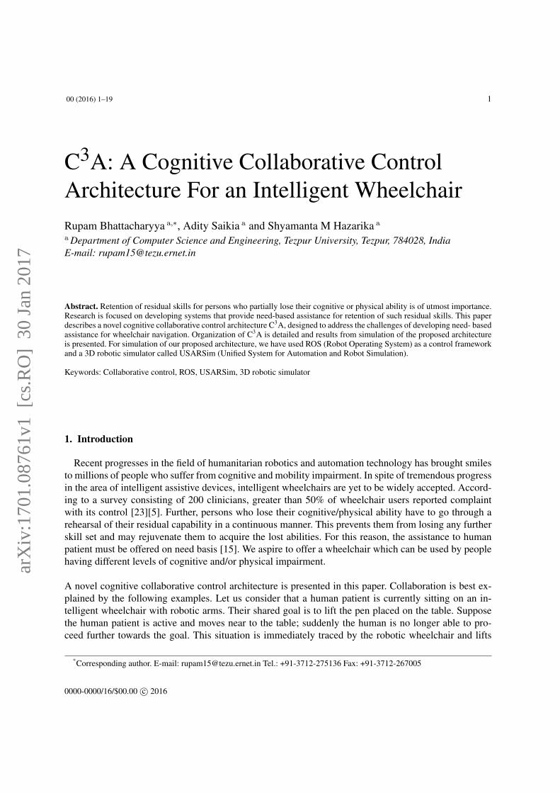
The proposed cognitive collaborative control architecture is shown in Figure 1. It is inspired fromthe work [11] and adaptation of well established cognitive architecture, ACT-R [19]. C3A is a layeredarchitecture with the following layers:
• User Interface Layer,• Superior Control Layer and• Local Control Layer.
The functionality of each layer and the inter dependence among them are described below.
3.1. User Interface Layer
User has to interact with this layer for setting the shared goal in the environment. We have assumedthat the user of our system is visually active. User Interface Layer helps the users to navigate the P3ATthrough the maze environment with the help of keyboard. This layer is utilized by the users for interactingwith rest of the layers of C3A. The wheelchair will be used by people who have either physical disabilityor cognitive disability or both. So, it is essential for us to determine how much help the patient should beprovided so that their residual skill remains intact. There are various effective tests to measure the currenthealth status of the patient. In [9], they have conducted five tests to calculate the cognitive/physicaldisability score. The procedure followed by us to calculate the score can be found in the subsection 4.3.This score is stored in procedural memory of the memory module for future usage. Later on, the score isfed to the heuristic engine of the reactive module for further processing.
3.2. Superior Control Layer
This layer is composed of two sub-modules;
• Reactive Module and• Reactive Navigator.
3.2.1. Reactive ModuleThis module is one of the important modules for proper functioning of the wheelchair. The reactive
module comprises of the following:
• Heuristic Engine,• Memory Module and
6 R. Bhattacharyya et al. / Tezpur University, India, Year: 2012-2014
Fig. 1. Cognitive Collaborative Control Architecture
• Interaction Layer.
1. Heuristic Engine The control architecture given in the Figure 1 is followed by both the machineand human. These type of architectures designed for rehabilitation of patients should consist of moduleswhich corresponds to constant monitoring of local efficiencies of human/robot command or predictionof intention of human as a driver or measuring the physiological state of the human. A method has beenproposed in [9] to calculate local efficiencies of human as well as robot. Similarly in [39], an approachfor intention prediction is given. Heuristic engine utilize the score from procedural memory to produce

R. Bhattacharyya et al. / Tezpur University, India, Year: 2012-2014 7
a priority configuration file. This file contains the priority of two modes of operation (human user andmachine) of the P3AT robot. The users with low cognitive score should be allowed to drive the P3ATcarefully. The intervention level of the system will be more and machine should take back the controlfrom the user as and when required. On the other hand the system’s intervention is less while the P3ATis driven by users with high cognitive score.
Heuristic engine uses shared goal location(i,j) and agent position(i,j) with respect to maze environmentto produce a performance related metric called distance. This metric along with the priority configurationfile will identify the quality of driving of the cognitive agent. The heuristic engine can guide us to modelan effective collaborator.
2. Memory Module
• Procedural memory,• Episodic memory and• Semantic memory.
One important design issue related to memory module is to identify which of the outputs of differentmodules will go into which memory structure. Clear distinction among different memory structures isgiven in [13].
a. Procedural memoryIt is concerned with how things are done [13]. In achieving a particular shared goal, it is indeed an in-evitable memory structure which utilizes perception, cognitive and motor skills of the agent. State andaction of agents in mobile robotics plays a vital role. Planning language help us to formalize the struc-ture of states and actions. The states and actions of the cognitive agent will be included in proceduralmemory. The cognitive and physical ability score is another entry into this memory structure from theuser interface layer.
b. Episodic MemoryIt is concerned with the remembrance of personally experience event [13]. The human Wayfinding be-haviour as explained in [4] follows different strategies to traverse the maze successfully. If we considerCentral Point Strategy of [4], then there must be specific states and their corresponding sequence ofactions that the agent tries to remember. Agent may also be interested in states and actions of two modesof operation; because in the middle of the simulation human users’ incapability allows the shifting ofcontrol to automated navigator of ROS.
c. Semantic memoryThis memory structure will provide context i.e. from procedural memory it can collect certain states andactions and based on which semantic memory try to assign meaning to the current situation.
Our future aim is to formalize the states and action of the cognitive agent. For the time being, the statesare internal to ROS environment and actions of all the modules are the result of different packages con-currently executing. For successful functioning of the whole system, all packages are dependent on eachother through the publisher-subscriber mechanism of ROS.

8 R. Bhattacharyya et al. / Tezpur University, India, Year: 2012-2014
3. Interaction LayerThis sub-module act like a communication backbone for entire architecture. It simultaneously interactswith the heuristic engine, memory module and reactive navigator. Thus we have two communicationpaths.
• Heuristic Engine-Interaction Layer-Reactive Navigator• Memory Module-Interaction Layer-Reactive Navigator
a. Heuristic Engine-Interaction Layer-Reactive Navigator:Heuristic Engine provides us the smart driver at any instant of time with the help of procedural memory.From the User Interface Layer(see Figure 1), procedural memory receives cognitive score (no label),goal location (label 3 of Figure 1) and agent position(label 6 of Figure 1). These three information isutilized by heuristic engine to constitute two metrics (explained in subsection 4.1) for choosing the smartdriver. When the wheelchair is run for the first time, then interaction layer access these metrics fromheuristic engine to invoke anyone of the two sub-modules of the reactive navigator. The communicationpath is described in table 2. With the help of heuristic engine, interaction layer have to dynamically track
Table 2 : Detailed Specification of Heuristic Engine-Interaction Layer-Reactive Navigator Communication PathInput (From | To) Label on Architec-
ture(figure 1)Functionality
Heuristic Engine | Interaction Layer 4 Metric to choose smart driver at any instantof time.
Reactive Navigator | Interaction Layer 1 States and action of the agentReactive Navigator | Interaction Layer 2 Maps of the environment generated by the
map_saver utility of ROS. This inputspecifically comes from the automated navi-gator of ROS. Agent Position(x, y) is calcu-lated with respect to this map.
Reactive Navigator | Interaction Layer 6 Agent Position(x, y) is produced in the mid-dle of simulation by the agent and stored inprocedural memory via the interaction layer.
which component of the reactive navigator has to be invoked. So, interaction layer also communicateswith the memory module for states and action sequences (label 1 from Figure 1) along with the agentposition(label 6 of Figure 1).
b. Memory Module-Interaction Layer-Reactive NavigatorThis communication path is described through table 3 and table 4. Table 3 focuses on the communicationhappening between interaction layer and automated navigator(mostly reactive navigator). On the otherhand, table 4 focuses on the communication happening between memory module and interaction layer.Most of the labels (label 6, 4, 3, 2, 1) on the C3A (Figure 1) have already been explained in the previouscommunication path.
The physical interaction through the User Interface Layer(see Figure 1) leads to change in various pa-rameters shown through different labels in the C3A. Thus, it is the responsibility of the interaction layerto be aware of such kind changes in the simulation environment. Labels 7 and 5 (of Figure 1) representsthe storage and retrieval of the specific states and action sequences of the agent which corresponds to

R. Bhattacharyya et al. / Tezpur University, India, Year: 2012-2014 9
specific event in episodic memory of the memory module respectively. This happens through the inter-action layer and implementation related to episodic memory is kept as future work.
Table 3 : Detailed Specification of Memory Module-Interaction Layer-Reactive Navigator Communication PathInput (From | To) Label on Architec-
ture(figure 1)Functionality
Interaction Layer | Reactive Navigator 4 Metric to choose smart driver at any instantof time.
Interaction Layer | Reactive Navigator 3 Goal position is used by the agent to moveto the shared goal
Interaction Layer | Reactive Navigator 5 Specific action sequences and states of anyof the agent related to a particular event.
Interaction Layer | Reactive Navigator 6 Agent’s localization information and is vitalfor the agent to trace the progress in achiev-ing the shared goal.
Interaction Layer | Reactive Navigator 1 States and action of the agentInteraction Layer | Automated Navigator 2 Map of the maze environment and used by
the global planner for planning the naviga-tion strategy. Human patient can view the 2Dmap while reaching to goal state. This 2Dmap is generated by SLAM module of Au-tomated Navigator of ROS and resembles to3D version of the maze environment.
Table 4 : Detailed Specification of Memory Module-Interaction Layer CommunicationInput (From | To) Label on Architec-
ture(figure 1)Functionality
Memory Module | Interaction Layer 3 The goal (i, j) is the co-ordinate of the goalposition as given by the human patient andstored in the procedural memory.
Memory Module | Interaction Layer 6 The Agent Position(x, y) is retrieved by theinteraction layer from procedural memory.
Memory Module | Interaction Layer 1,2 Retrieved from procedural memory by theinteraction layer and finally fed to the reac-tive navigator.
Memory Module | Interaction Layer 5 Specific states and actions corresponding tospecific episode. It is retrieved by interactionlayer from episodic memory.
Interaction Layer | Memory Module 7 It is result of the processing of the statesand actions of the agent by the interactionlayer. These things are combined in such away that they collectively represent a pecu-liar event during simulation.
Interaction Layer | Memory Module 1,2,6 Already explained above
3.2.2. Reactive NavigatorBefore building a reactive navigator, system designer needs to be very focused in the speed sensitive
parts of the cognitive architecture. In, improving the speed sensitive information, ROS introduces a new

10 R. Bhattacharyya et al. / Tezpur University, India, Year: 2012-2014
concept called “nodelets" which helps us to build reactive controller. These are almost similar to conven-tional nodes but lots of important features are embedded into it. Reactive navigator is composed of twosub-modules which is part of ROS control framework:
• Automated Navigator of ROS and• Patient as Driver.
a. Automated Navigator of ROS:ROS is composed of number of complex tools and libraries. Incorporation of details about automated
Fig. 2. Communication between USARSim Simulator and ROS
navigator will make the architecture shown in figure 1 clumsy. Our motivation is that the complexity ofROS should not dominate the understanding of our control architecture.The automated navigator of ROSis the machine in our approach.
Planning is essential for guiding the agent autonomously without causing any harm. Global planner is re-lated to creating long term plans over the entire environment [31] and it takes input from global costmapas shown in figure 3. Local planner is mainly used for obstacle avoidance which uses Local costmap.The costmap_2d package of ROS provides a structure which is configurable. This package maintainsinformation about where should the robot navigate in the form of an occupancy grid [12]. Thus globalplanner and local planner with the information of pose estimate from AMCL (Adaptive Monte CarloLocalization) and obstacle information from costmap can plan effectively to reach the shared goal. Thesensor data (in our case SICK LMS200) may be utilized in building both the costmaps.
The text that is written in communication lines (shown in figure 3) will reflect the key functionalityof individual sub modules. Figure 2 describes the communication between Reactive Navigator and Lo-cal Control Layer. It depicts the communication involved in implementing our architecture integrating

R. Bhattacharyya et al. / Tezpur University, India, Year: 2012-2014 11
USARSim and ROS control framework. It will help the reader to understand the C3A in a better way.Figure 3 describes the internal message passing between sub- modules of Automated Navigator of ROS.This figure gives detailed understanding of the how the agent can move autonomously.
The functionality of Automated navigator of ROS is achieved through a ROS node called move_base.This node is customized to modify the reactive behaviour (figure 3) ; so that collaboration can beachieved.b. Patient as Driver:
Fig. 3. Automated navigator of ROS with USARSimRos interface
This sub module uses ROS tele-operation to move around the maze environment through the keyboard.The ROS node is teleop_twist_keyboard [36] and corresponds to the package brown_remotelab[7].
3.3. Local Control Layer
This layer corresponds to the 3D USARSim simulator where both the P3AT robot and maze environ-ment co-exist simultaneously. P3AT robot uses SICK LMS200 laser range finder. It can be augmentedwith many other sensors. This sensor is an integral part of local control layer. All the actuators arealso part of this layer. Whenever the agent is tested in real time environment, then we need a real timewheelchair. All the sensors, actuators and other hardware related aspects present in P3AT must be em-bedded inside the real time wheelchair.

12 R. Bhattacharyya et al. / Tezpur University, India, Year: 2012-2014
4. Simulation
4.1. Evaluation Metrics
There are lots of metrics [3] are suggested to test the performance of human-robot application. For ex-perimental evaluation of the collaborative control of the P3AT robot, two types of metrics are considered.
• Condition related metric and• Performance related metric.
Condition related metric It determines the cognitive status of the user of the wheelchair. This score leadsto a priority configuration file. The ROS node, Cognitive_Score [see Table5] designed by us dealswith the computation of this metric.Performance related metric This metric is related to effective collaboration and finding out the efficiencyof the agent while driving the P3AT. Agent drives the P3AT under two explicit modes of operationnamely,
• teleoperation (human is controlling the P3AT through keyboard) and• Machine (Automated Navigator of ROS drives the P3AT).
Implicitly collaborative mode is enforced as discussed below.
Distance between the current position of the P3AT and shared goal location with respect to themaze environment is selected as the performance metric. This distance is dynamically calculated. TheVelocity_multiplexer node and move_base node [see Table5] are customized in such a waythat the condition related metric along with performance related metric gives an effective way for thehuman to collaborate smoothly with its machine counterpart.
The system behaviour can be understood by considering two scenarios.Scenario: 1Suppose, human is controlling the P3AT and the metric indicates that P3AT is moving away from thegoal. In this situation, as soon as human pauses (releases the keyboard) for a moment, then MACHINEinstantly takes over the Control of P3AT. We are considering implicit communication without prior co-ordination. There is no explicit consensus between the two parties, but system treats this whole scenarioas a situation where assistance is required. Users can always take back the control from machine when-ever it is desired to do so. Thus, human is not kept away from the control loop of the system. Our aim isto allow user to utilize their own motor and cognitive skills.Scenario: 2Let us say, currently wheelchair is driven by human. Suppose the metric indicates that distance is reduc-ing towards goal which indirectly tells about the good driving skills of the driver. So, right now even ifhuman pauses for a moment, then MACHINE won’t be able to take over the Control.
The behaviour of above two scenarios will be same when machine is considered to drive the robot. AFinite State Machine (FSM) is shown in figure 4 which will help the readers to understand the flow of theentire architecture. Figure 5 can be used to describe the two scenarios involving collaboration. Circlesmarked in figure 5 are the important zones. Pink cursor in Circle A shows the shared goal, the P3ATrobot can be seen as the box outlined with light green boundary.Circle A is the area where human is driving the robot well; this represent the Scenario 2 described above.

R. Bhattacharyya et al. / Tezpur University, India, Year: 2012-2014 13
Fig. 4. FSM describing entire flow of the architecture.
Circle B and Circle C represent area where human is moving away from the shared goal. In such asituation, MACHINE takes over the control of the P3AT robot. MACHINE corrects the erratic drivingbehaviour of the human by taking over the control of the robot. Scenario 1 is visualized through thesecircles.
4.2. Experimental Set Up
The experimental simulation set up is shown in figure 6. To start the services of different ROS nodes, auniversal launch file is created. Simulation starts from a “form fill-up" process by the user. It is followedby launching the testing arena which is the maze environment. This maze is designed using “UnrealDevelopment Kit" which is embedded inside USARSim simulator. The same maze is utilized for testingall the participants. Except for the testing arena, every other utility is provided through ROS nodes. Table5 gives a detailed specification of the functionality of different ROS nodes and their correspondence with

14 R. Bhattacharyya et al. / Tezpur University, India, Year: 2012-2014
Fig. 5. Collaboration between man and machine in USARSim-ROS environment
Fig. 6. Experimental simulation set up
C3A. Experimentation can start only after all nodes mentioned in table 5 functions properly3.
3Interested readers can access https://drive.google.com/file/d/0BwgHQRnAyRbgWXhhdWxlN0ctU0k/view?usp=sharing topreview the snapshot of our whole system (the graph of the whole simulation when all ROS nodes are correctly running) in asuccessful scenario.

R. Bhattacharyya et al. / Tezpur University, India, Year: 2012-2014 15
Table 5 : Detailed Specification of ROS nodes running inside the cognitive agent.ROS Node Functionality Correspondance with the Col-
laborative Control ArchitectureRosSim 1. Provides interface be-
tween ROS and USARSim,2. helps in spawning a robot in USARSim,3. Auto-discovering the robot’s sensors,actuators
Resides in Local Control Layerand provides service to Supe-rior Control Layer
teleop_twist_keyboard With the help of it Users can drive a robotthrough keyboard
Local Control layer
amcl amcl is a probabilistic localization systemfor a robot moving in 2D
Reactive Navigator
slam_gmapping provides SLAM capabilities Reactive Navigatormove_base given a goal in the world, it will attempt to
reach it with a mobile base.Automated navigator of ROS
nodelet_manager Implements nodelets Reactive ModuleVelocity_multiplexer Multiplexes the velocity commands coming
from teleop_twist_keyboard and move_basenode.
Reactive Module
Cognitive_Score Generate a priority configuration file whichis used by Velocity_multiplexer node.
User Interface Layer
rviz Visualization tool for setting shared goal Superior Control Layermap_server allows dynamically generated maps to be
saved to file.Reactive Navigator
The initial launching location of P3AT robot is same for all the participants. The term “shared goal"is vital for any collaborative system. We have assumed that the user can clearly locate the shared goalthrough the User Interface Layer. In this simulation, users can set a goal via ‘rviz’ window throughmouse-click/touch-pad over 2D map generated through SLAM module. The “shared goal" is fixed in acorner of the maze for all participants. The ‘rviz’ package acts as visualisation tool for the ROS. So, incase of our C3A, the goal is universal; both machine and human can rely on it.
4.3. Experimentation
The cognitive collaborative control architecture is evaluated for its effectiveness by comparing the ma-noeuvring time (total time required from start to goal) under the following modes.1. human(standalone mode),2. machine (standalone mode) and3. collaborative control mode.The cognitive score of the subjects is based on the questionnaire from the table 6. Questions are adaptedfrom standard papers Instrumental activities of daily living (IADL)[27] and Folstein test or mini-mentalstate examination (MMSE)[33]. The questionnaire can be used as an instrument for analyzing the partic-ipants in a short period of time.Six subjects are taken in random. Each of them is made to go through the questionnaire; cognitive scoreis evaluated. There are two groups of people; group A having high cognitive score (HCS) and group Bwith low cognitive score (LCS). Four subjects belong to group A, as their cognitive score is more thanfive. Two persons belong to group B; as they score less than five. Table 7 shows the profile of six sub-

16 R. Bhattacharyya et al. / Tezpur University, India, Year: 2012-2014
Table 6 Questionnaire used for cognitive score determination
Questionnumber
Question Record Answer HereSecuredScore
1 Have you played any game before? Yes / No©Negative Response©Positive Response
2 Do you know about mazes? Yes / No©Negative Response©Positive Response
3 Can you solve a maze on paper? Yes / No©Negative Response©Positive Response
4Can you utilize essential features ofyour mobile phone?
Yes / No©Negative Response©Positive Response
5Can you prepare adequate meals ifsupplied with ingredients?
Yes / No©Negative Response©Positive Response
6 What is todayâAZs date? Date©Correct©Incorrect
7 What city are we in? City©Correct©Incorrect
8 Can you also tell me,what season it is? Season©Correct©Incorrect
9 What floor are we in? Floor©Correct©Incorrect
10 How many vowels in the word aeroplane? 4/ 5 / 6 / other©Correct©Incorrect
Deriving the total Cognitive score,i) Add 1 for each correct and positiveresponse given by the subject,ii) 0-4 = Low Cognitive Score (LCS)5-10= High Cognitive Score (HCS)
TotalScore=_____
(Maximum10)
jects that test our simulation. All the subjects are given three minutes to memorize/learn the navigation
commands and setting of global shared goal. Subjects are told about their task to be completed in the
simulated environment.

R. Bhattacharyya et al. / Tezpur University, India, Year: 2012-2014 17
Table 7 : cognitive score profiling and behavioural estimation through observationsubject_id Cognitive
ScoreGroupPlace-ment
Behavior(Observedduring simulation)
Cognition(Observedduring simulation)
Attentiveness (Ob-served during simu-lation)
subject_1 10 A Co-operative Good memory Very Attentivesubject_2 3 B Need encouragement Less skills related to
memorizing the Com-mands
Attentive.
subject_3 9 A None Good memory Attentivesubject_4 10 A Need encouragement Less skills related to
memorizing the Com-mands.
Less Attentive
subject_5 2 B Frustrated Easily,needs encouragement
Distractible, Lessskills related to memo-rizing the Commands
Attentive.
subject_6 10 A Co-operative Good memory and ex-pressiveness
Very Attentive
5. Results
Figure 7 reports the manoeuvring time (in seconds) required by all the six subjects to reach the pre-specified goal. All the three modes described in subsection 4.3 are shown in the figure 7. Machine timefor different runs is different. This is because of the way the machine navigates and users has nothingto do with this. The machine in our case is the automated navigator of ROS. This navigator generatesdifferent recovery behavior based on dynamic construction of Costmap. Costmap is built using the laserscans obtained from SICK LMS200 laser range finder. A single laser scan might not arrive in the sametime window between two sets of experiment leading to a different Costmap and thus behavior. Theperformance of the collaborative mode versus the human user (standalone mode) is compared to evaluatethe system. The autonomous navigation of ROS is highly configurable, making possible to use a largenumber of algorithms. The driving behavior of different users will be different if there are no trafficrules. In our maze, there is no driving rule to go to the shared goal. Thus, in two different trials, theuser commands will leave the whole system in two different situations. Thus, the planners inside themove_base node acts differently which gives rise to different completion time in collaborative controlmode.
As expected the time taken by the human to reach a particular goal is more as compared to drivingthe P3AT in collaborative mode. All the LCS group i.e. group B participants’ benefits from the C3A.Similar trend can be observed in most of the participants of the HCS group i.e. group A participants’.Note that an exception occurred in case of subject_4. Users were observed during simulation andsubjective estimation done. As seen from Table 7, subject_4 is less attentive and fails to memorizethe navigation commands properly; can not relate them to arrow keys. Even though, this subject is fromHCS group; its driving is erratic and frequently moves the robot away from the shared goal. Machinerequires more time to make corrections to bring the robot on-course, leading to increase in manoeuvringtime under collaboration.
Our architecture is not yet implemented in a real wheelchair. A differential model of the wheelchair hasto be created inside USARSim to replace the P3AT robot. Several real robots works successfully by

18 R. Bhattacharyya et al. / Tezpur University, India, Year: 2012-2014
Fig. 7. Time required with different subjects under three distinct modes of operation
using ROS which encourage us to believe that this initial simulation result is a good starting point tobuild a real one. The generalizable nature of our findings is an important issue to discuss here. Our claimis not to prove the generalized nature of our simulation result on different types of wheelchair users. Thisinitial research should be viewed as a new way to achieve the collaborative control by exploiting theopen Source research platform, ROS.
6. Final Comments
Robust real-world behavior can not be pre-programmed. ROS overcomes this limitation because ofits sound message passing and shared memory concept. The wheelchair control imbibing C3A is awareof its location, driver quality along with other environmental facts such as proximity towards the sharedgoal through the memory module. The navigation commands from user and the wheelchair are simulta-neously active through ROS topic. Assistive wheelchair with collaborative control is achieved by C3Athrough ROS is an approach of embodiment of cognition. ROS contains all the required features to buildan effective collaborative device.
The limitation of our approach are mentioned below:
– Our initial result with six participants is used to show that our approach has some positive directions.Rigorous testing with more users are possible; once we implement the whole memory module. Inour future work, we try to incorporate more evaluation metric and rigorous statistical analysis toimprove our approach towards collaborative control.
– For simulation reported in this paper, the user has to be visually active to set the shared goal andhave motor control to operate the keys.
The novelty of the paper is the development of C3A and the functionality of ROS is effectively utilised toanalyze the utility of collaborative control. This approach for designing cognitively enabled wheelchairintroduces several new research avenues within the ROS environment. Instead of using autonomousnavigator of ROS, agent can be programmed to use a planner designed using formal methods. Severalresearchers are working on EEG (electroencephalogram) based brain-actuated wheelchair system usingmotor imagery. Overcoming the above mentioned limitations by extending ROS is part of our ongoingresearch. Controlling the wheelchair through EEG is our future goal.

R. Bhattacharyya et al. / Tezpur University, India, Year: 2012-2014 19
References
[1] A. Bauer, D. Wollherr and M. Buss, Human-robot collaboration: a survey, in: International Journal of Humanoid Robotics,5(01), 2008, pp. 47-66.
[2] A. C . Schultz, Using computational cognitive models to build better human-robot interaction, in: NAE US FOE Sympo-sium, 2006.
[3] A. Steinfeld, T. Fong, D. Kaber, M. Lewis, J. Scholtz, A. Schultz, and M. Goodrich. Common metrics for human-robotinteraction, in: Proceedings of the 1st ACM SIGCHI/SIGART Conference on Human-robot Interaction (HRI ’06), NewYork, USA, 2006, pp. 33-40.
[4] A. Saikia and S. M. Hazarika, Solving a Maze: Experimental Exploration on Wayfinding Behaviour for Cognitively En-hanced Collaborative Control, in: Intelligent Interactive Technologies and Multimedia, Springer Berlin Heidelberg, 2013,163-177.
[5] B. D. Argall, Machine Learning for Shared Control with Assistive Machines, in: Proceedings of ICRA Workshop onAutonomous Learning: From Machine Learning to Learning in Real world Autonomous Systems, Karlsruhe, Germany,May 2013.
[6] B. Sathish Babu, (n.d.). Cognitive agents, 1st ed. [ebook] Retrieved from: pet.ece.iisc.ernet.in/sathish/cognitive.pdf[7] C. Crick, T. Jay and S. Osentoski(2011), brown_remotelab - ROS Wiki. [online] Wiki.ros.org. Retrieved from:
http://wiki.ros.org/brown_remotelab.[8] C. Urdiales, From shared control to collaborative navigation, in: Collaborative Assistive Robot for Mobility Enhancement
(CARMEN), volume 27 of Intelligent Systems Reference Library, Springer Berlin Heidelberg, 2012, pages 41-66.[9] C. Urdiales, et al., Wheelchair collaborative control for disabled users navigating indoors, in: Artif. Intell. Med, Vol. 52,
2011, pp. 177-191.[10] D. Kortenkamp. Designing an architecture for adjustably autonomous robot teams, in: R. Kowalczyk, S. Loke, N. Reed,
and G. Williams, editors, Advances in Artificial Intelligence, PRICAI 2000 Workshop Reader, volume 2112 of LectureNotes in Computer Science, Springer Berlin Heidelberg, 2001, 335-338.
[11] E. Marder-Eppstein, (2012). move_base - ROS Wiki. [online] Wiki.ros.org. Retrieved from:http://wiki.ros.org/move_base.
[12] E. Marder Eppstein, (2010). costmap_2d - ROS Wiki. [online] Wiki.ros.org. Retrieved from:http://wiki.ros.org/costmap_2d.
[13] E. Tulving, Memory and consciousness, in: Canadian Psychology/Psychologie canadienne, Vol 26(1), Jan 1985, 1-12,doi:10.1037/h0080017.
[14] F. Heger, L. Hiatt, B. Sellner, R. Simmons, and S. Singh, Results in sliding autonomy for multi-robot spatial assembly, in:8th International Symposium on Artificial Intelligence, Robotics and Automation in Space (iSAIRAS), 2005, 5-8.
[15] G. E. Gresham et al., Prevention and rehabilitation of stroke, in: Stroke, 28(7), 1997, pp. 1522-1526.[16] J. A. Adams, P. Rani, and N. Sarkar (2004). Mixed initiative interaction and robotic systems, in: Workshop on Supervisory
Control of Learning and Adaptive Systems, in: Nineteenth National Conference on Artificial Intelligence (AAAI-04), SanJose, CA, USA.
[17] J. Brookshire, S. Singh and R. Simmons, Preliminary results in sliding autonomy for coordinated teams, in: Proceedingsof The 2004 Spring Symposium Series, 2004.
[18] J. E. Allen and C. Guinn, Mixed-initiative interaction, in: Intelligent Systems and their Applications, IEEE, 14(5), 1999,14-23.
[19] J. R. Anderson and C. Lebiere, "The Newell test for a theory of cognition." in: Behavioral and brain Sciences, 26 (05),2003, pp. 587-601.
[20] J. Laird, A. Newell and P. Rosenbloom, Soar: An architecture for general intelligence, in: Artificial Intelligence, 33 , 1987,1-64.
[21] J. W. Kim and F. .E. Ritter (2012). ACT-R Frequently Asked Questions List. [online] Acs.ist.psu.edu. Retrieved from:http://acs.ist.psu.edu/projects/act-r-faq/act-r-faq.html
[22] K. Kawamura, P. Nilas, K. Muguruma, J. Adams, and C. Zhou, An agent-based architecture for an adaptive human-robotinterface, in: Proceedings of the 36th Annual Hawaii International Conference on System Sciences, 2003, pp. 126.2.
[23] L. Fehr, W. E. Langbein, and S. B. Skaar, Adequacy of power wheelchair control interfaces for persons with severedisabilities : A clinical survey, in: Journal of Rehabilitation Research and Development, 37(3), 2000, pp. 353-360.
[24] M. A. Goodrich and A. C. Schultz, Human-robot interaction: a survey, in: Foundations and trends in human-computerinteraction, 1(3), 2007, pp. 203-275.
[25] M. Johnson, J. M. Bradshaw, P. J. Feltovich, C. M. Jonker, B. van Riemsdijk, and M. Sierhuis, The fundamental principleof coactive design: interdependence must shape autonomy, in: Coordination, Organizations, Institutions, and Norms inAgent Systems VI, Springer Berlin Heidelberg, 2011, 172-191.
[26] M. N. Huhns and M.P. Singh, Cognitive agents, IEEE, in: Internet Comput., November/December ( 1998), pp. 87-89.

20 R. Bhattacharyya et al. / Tezpur University, India, Year: 2012-2014
[27] M. Lawton and E. Brody, Assessment of older people: self-maintaining and instrumental activities of daily living, in:Gerontologist, 9, 1969, 179-85.
[28] M. Quigley, et al., ROS: an open-source Robot Operating System, in: ICRA workshop on open source software, Volume.3. No. 2, 2009.
[29] M. Wooldridge and N. R. Jennings, Agent Theories, Architectures, and Languages: a Survey, in Wooldridge and Jenningseds., Intelligent Agents, Springer-Verlag, 1995, 1-22.
[30] P. Langley, An adaptive architecture for physical agents, in: Proc. IEEE/WIC/ACM Int. Conf. Intell. Agent Technol.,Compiegne, France, 2005, pp. 18-25.
[31] P. Yoonseok(2014), Navigation/Tutorials/Robotsetup-ROS Wiki, [online] Wiki.ros.org. Retrieved from:http://wiki.ros.org/navigation/Tutorials/RobotSetup.
[32] R. A. Brooks., A robust layered control system for a mobile robot, in: IEEE Journal of Robotics and Automation, 2(1),1986, pp. 14-23.
[33] R. Crum , J. Anthony, S. Bassett and M. Folstein, "Population-based norms for the mini-mental state examination by ageand educational level.", in: Journal of the American Medical Association, 269(18), 1993, pp. 2386-3239.
[34] R. Simpson, Smart wheelchairs: A literature review., in: J. Rehabil. Res. Dev., 42(4), 2005, 423-436.[35] S. Balakirsky (2013). USARSim. [online] SourceForge. Retrieved from: http://sourceforge.net/projects/usarsim/.[36] S. B. Balakirsky and Z. Kootbally, USARSim/ROS: A Combined Framework for Robotic Control and Simulation, in:
Proceedings of the ASME 2012 International Symposium on Flexible Automation (ISFA 2012), St. Louis, June 18-20,2012.
[37] S. J. Russell and P. Norvig, Artificial Intelligence, Englewood Cliffs, N.J.: Prentice Hall, 1995. Print.[38] S. Rosenthal, and M. Veloso, Using symbiotic relationships with humans to help robots overcome limitations, in: Work-
shop for Collaborative Human/AI Control for Interactive Experiences, 2010.[39] T. E. Carlson, Collaborative control mechanisms for an intelligent robotic wheelchair, Ph.D. Dissertation, Imperial College
London (University of London), 2010.[40] B. D. Argall, Modular and adaptive wheelchair automation, in: Experimental Robotics, Springer International Publishing,
2016.[41] Y. Kang, et al., Stability analysis of a class of hybrid stochastic retarded systems under asynchronous switching, in: IEEE
Transactions on Automatic Control, 59 (6), 2014, pp. 1511-1523.[42] Y. Kang, et al., On Input-to-State Stability of Switched Stochastic Nonlinear Systems Under Extended Asynchronous
Switching, in: IEEE transactions on cybernetics, 46 (5), 2016, pp. 1092-1105.[43] R. Zhang et al., Control of a Wheelchair in an Indoor Environment Based on a BrainâASComputer Interface and Auto-
mated Navigation, in: IEEE transactions on neural systems and rehabilitation engineering, 24 (1), 2016, pp. 128-139.[44] K. Ericson, S. Pallickara, and C. W. Anderson, Analyzing electroencephalograms using cloud computing techniques, in:
Proceedings of the Second (IEEE) International Conference on Cloud Computing Technology and Science (CloudCom),USA, 2010.
Related Documents