A Code of Practice for the Calibration of Industrial Process Weighing Systems WGC0496 Originally Published 1996 Reviewed and Re-issued 2003

Welcome message from author
This document is posted to help you gain knowledge. Please leave a comment to let me know what you think about it! Share it to your friends and learn new things together.
Transcript
A Code of Practice for the Calibration of
Industrial Process Weighing Systems
WGC0496
Originally Published 1996
Reviewed and Re-issued 2003


COMMITTEE RESPONSIBLE FOR THIS CODE OF PRACTICE This Institute of Measurement and Control Code of Practice has been prepared by the Weighing Group reporting to the Physical Measurements Panel and adopted by the United Kingdom Weighing Federation. The persons listed below served as members of the Weighing Group in preparing this Document. U Erdem, Chairman Negretti Automation Ltd. P Zecchin, Deputy Chairman Nobel Systems Ltd. J Anthony UK Weighing Federation T Bowen Davy International Weighing Systems N S Fox Warwickshire CC, TSD D Green DCG Associates D Hayward UKAS R F Jenkins National Physical Laboratory C M Marklew Nova Weigh Ltd. D J Phillips QSRMC Prof. J Pugh Glasgow Caledonian University C G Whittingham British Steel, Scunthorpe The Group would like to extend special thanks to Juliette Coopey and Colin Carter of the Institute of Measurement and Control Secretariat for their support throughout the project. This Code of Practice is subject to review at any time by the responsible technical group of the Institute. It was reviewed in 2003 and re-issued in PDF format. The current Weighing Panel would like to extend special thanks to Andy Knott of the National Physical Laboratory for his contribution. The Institute welcomes all comments on this Document and requests that these be addressed to the Institute. Users of this Institute of Measurement and Control Code of Practice shall be responsible for its correct application. ISBN 0 904457 23 0 The Institute of Measurement and Control, 87 Gower Street, London WC1E 6AF
WARNING DUE CONSIDERATION SHALL BE GIVEN TO THE SAFETY AND
ENVIRONMENTAL ASPECTS OF ALL OPERATIONS AND PROCEDURES DURING THE CALIBRATION. FORMAL APPROVAL SHALL BE SOUGHT WHEN THE CALIBRATION IS PLANNED IN A
POTENTIALLY HAZARDOUS AREA.
Code of Practice for the Calibration of Industrial Process Weighing Systems, October 2003 1
CONTENTS PAGE 1 FOREWORD 6 2 SCOPE 6 3 TERMS AND DEFINITIONS 7 4 GENERAL REQUIREMENTS FOR CALIBRATION 12 4.1 GENERAL 12 4.2 MEASUREMENT STANDARDS 12 4.3 TRACEABILITY OF CALIBRATION EQUIPMENT 12 4.4 METHOD OF LOADING 12 4.4.1 General considerations 12 4.4.2 Calibration 12 4.4.3 Revalidation 13 4.4.4 Warm up period 13 4.4.5 Preloading 13 4.5 TEMPERATURE EFFECTS 13 4.6 RECORDS 13 4.7 FREQUENCY OF CALIBRATION 13 4.7.1 Initial choice of confirmation intervals 13 4.7.2 Review of confirmation intervals 13 4.8 INDICATION OF CALIBRATION STATUS AND SEALING FOR
INTEGRITY 14 4.9 CALIBRATION CERTIFICATE 14 5 METHODS OF CALIBRATION 15 5.1 CALIBRATION PROCEDURE USING STANDARD WEIGHTS 15 5.1.1 Introduction 15 5.1.2 Specific requirements prior to calibration 15 5.1.3 Calibration procedure 15 5.1.4 Uncertainty of calibration load 15 5.2 CALIBRATION PROCEDURE USING REFERENCE WEIGHTS 15 5.2.1 Introduction 15 5.2.2 Specific requirements prior to calibration 15 5.2.3 Calibration Procedure 16 5.2.4 Uncertainty of calibration load 16 5.3 CALIBRATION PROCEDURE USING SUBSTITUTE MATERIAL 16 5.3.1 Introduction 16 5.3.2 Specific requirements prior to calibration 16 5.3.3 Calibration procedure 16 5.3.4 Uncertainty of calibration load 17 5.4 CALIBRATION PROCEDURE USING FORCE TRANSFER METHOD 17 5.4.1 Introduction 17 5.4.2 Specific requirements prior to calibration 17 5.4.3 Calibration procedure 18 5.4.4 Uncertainty of Calibration load 18 5.5 CALIBRATION PROCEDURE USING METERED FLOW 19 5.5.1 Introduction 19 5.5.2 Specific requirements prior to calibration 19 5.5.3 Calibration Procedure 19
2 Code of Practice for the Calibration of Industrial Process Weighing Systems, October 2003
5.5.4 Conversion of flow meter reading to actual flow 20 5.5.5 Uncertainty of calibration load 20 5.5.6 Correction for Density 20 5.6 CALIBRATION PROCEDURE USING PROVING TANKS 23 5.6.1 Introduction 23 5.6.2 Specific requirements prior to calibration 23 5.6.3 Calibration Procedure 23 5.6.4 Uncertainty of calibration load 23 5.6.5 Correction for Density 24 5.7 CALIBRATION PROCEDURE USING METHODS REMOTE TO THE
OPERATING INSTALLATION 24 5.7.1 Introduction 24 5.7.2 Specific requirements prior to calibration 24 5.7.3 Calibration procedure 24 5.7.4 Uncertainty of calibration load 25 6 QUALITY OF SERVICE 26 ANNEX I A1. GENERAL CONSIDERATIONS 27 A1.1 INFLUENCE QUANTITIES 27 A1.2 PORTABLE WEIGHING SYSTEMS 28 A1.3 AIR BUOYANCY EFFECT 28 A1.4 WEIGHING SYSTEM INCORPORATING DUMMY LOAD CELLS OR
PIVOTS 29 A1.5 INFLUENCE OF ZERO TRACKING 29 ANNEX II A2. CALIBRATION OF WEIGHING SYSTEM COMPONENTS 30 A2.1 USE OF LOAD CELL SIMULATOR 30 A2.1.1 Introduction. 30 A2.1.2 Specific requirements 30 A2.1.3 Procedure 30 A2.1.4 Guidance on using a load cell simulator 30 A2.1.5 Uncertainty of simulated load 31 A2.2 USE OF MILLIVOLT SOURCE 31 A2.2.1 Introduction 31 A2.2.2 Specific requirements 31 A2.2.3 Procedure 31 A2.2.4 Uncertainty of simulated load 31 A2.3 USE OF SHUNT RESISTORS 31 A2.3.1 Introduction 31 A2.3.2 Specific requirements prior to calibration 32 A2.3.3 Procedure 32 A2.3.4 Guidance on using shunt calibration resistors 32 A2.4 USE OF THEORETICAL CALCULATIONS 32 A2.4.1 Introduction 32 A2.4.2 Specific requirements 33 A2.4.3 Procedure 33 A2.4.4 Guidance on the method of combining calibration data 33 A2.4.5 Uncertainty of calibration load 33
Code of Practice for the Calibration of Industrial Process Weighing Systems, October 2003 3

A2.5 REVALIDATION OF LEVER SYSTEMS 33 A2.5.1 Introduction 33 A2.5.2 Specific requirements 34 A2.5.3 Procedure 34 A2.5.4 Uncertainty of applied load 34 ANNEX III A3. PROCESSING OF CALIBRATION DATA 35 A3.1 Calculation of non-linearity using the best straight line method 35 A3.2 Calculation of non-linearity using the terminal line method 35 A3.3 Calculation of non-linearity (decreasing) using the best straight line method 35 A3.4 Calculation of non-linearity (decreasing) using the terminal line method 35 A3.5 Calculation of hysteresis 35 A3.6 Calculation of combined error, using the best straight line method 35 A3.7 Calculation of combined error, using the terminal line method 36 A3.8 Calculation of repeatability 36 ANNEX IV A4. TEST PROCEDURES AND PROCESSING OF TEST DATA 37 A4.1 Determination of eccentric loading effects 37 A4.2 Calculation of eccentric loading effects 37 A4.3 Determination of incremental error 37 A4.4 Calculation of incremental error 38 ANNEX V A5. EXAMPLE OF CALIBRATION CERTIFICATE 39 ANNEX VI A6. CONVERSION FACTORS FOR MASS AND FORCE, AND A LIST OF
USEFUL CONSTANTS 42 Table 1 Comparison of typical uncertainty of measurements for different methods
of calibration 43 Table 2 Maximum permissible errors for standard weights as defined in OIML R111 44 Figure 1 Illustration of certain weighing terms 45 Figure 2 Generic industrial weighing system 45 Figure 3 Representation of errors based on terminal straight line 46 Figure 4a Representation of combined error based on best straight line through zero 47 Figure 4b Representation of non-linearity based on best straight line through zero 48 Figure 5a Example of calibration by force transfer standard (series) 49
4 Code of Practice for the Calibration of Industrial Process Weighing Systems, October 2003
Figure 5b Example of calibration by force transfer standard (series, using a pressure
gauge as the load indicator) 49 Figure 5c Example of calibration by force transfer standard (series) 49 Figure 6 Example of calibration by force transfer standard (parallel) 50 Figure 7 Calibration by flow meter, general arrangement 50 BIBLIOGRAPHY 51
Code of Practice for the Calibration of Industrial Process Weighing Systems, October 2003 5
1 FOREWORD
This Institute of Measurement and Control Code of Practice establishes uniform criteria for the calibration of industrial process weighing systems incorporating load cells as components in applications other than those covered by the Statutory requirements such as in trade weighing.
It gives recognition to the need for a comprehensive and authoritative document for the calibration of industrial process weighing systems.
This Document is a guide for technical personnel and organisations engaged in calibration of industrial process weighing systems. It is expected that the competence of the calibration authority is established and appropriate accreditation obtained.
It is prepared to meet the requirements of the now well established and accepted BS EN ISO 9000 series of Quality management and quality assurance standards.
The proposed guidelines are intended for those systems which are already commissioned and in good working order and comply with all the current safety and regulatory requirements as relevant.
2 SCOPE
This Code of Practice reviews various techniques for the calibration of industrial process weighing systems.
The methods described address static calibration of weighing systems. Calibration of dynamic weighing systems such as belt weighers, in-motion weighbridges and closed loop control of batched ingredients are excluded.
Each method is described in a formal statement of procedure supplemented by practical application and performance topics.
The term ‘Calibration’, within the context of this Code of Practice means carrying out a set of operations, which establish. under reported conditions, the relationship between the weighing system output and corresponding known values of load applied to the weighing structure. The result of the calibration is reported in a formal document entitled calibration certificate or certificate of calibration.
The data obtained as a result of the calibration operation may be used to estimate the weighing system errors or adjust the system output to an agreed specific value.
6 Code of Practice for the Calibration of Industrial Process Weighing Systems, October 2003
3 TERMS AND DEFINITIONS
This Code of Practice provides recommended terminology and definitions pertaining to the calibration of industrial process weighing systems. The following definitions have been limited to those widely used in the Weighing Industry and also those which are necessary for the calibration of the industrial weighing systems.
Where appropriate these terms and definitions are based on BS EN 45501 : 1994 Specification for metrological aspects of non-automatic weighing instruments and BS 5233 : 1986(1993) Glossary of terms used in metrology.
Refer to figures 1, 2, 3 and 4 for graphical representation of certain weighing terms.
3.1 Accuracy of measurement: the closeness of the agreement between the result of a load measurement and the true value of the load. The term is unhelpful and is not freely used here. Definitions like uncertainty of measurement. non-linearity, combined error and hysteresis are preferred.
3.2 Adjustment of calibration parameters: the operation intended to bring the weighing system output within a specified agreement to the load applied.
3.3 Applied load: within the context of this Document, the load applied to the weighing system for the purpose of calibration.
3.4 Blind amplifier: see Transmitter
3.5 Calibration: the set of operations which establish under specified conditions the relationship between the values of load applied and the corresponding value of the weighing system output. Note: Calibration does not include adjustment. See subsection 3.2.
3.6 Calibration Certificate: a formal and structured document reporting the results of calibration and , where appropriate, relevant findings and observations. See Annex 5.
3.7 Calibration curve: the presentation of calibration results in graphical format.
3.8 Capacity, maximum operating: the maximum load that will be applied to the load receiving element under normal operating conditions.
3.9 Capacity, minimum operating: value of load applied to the load receiving element, below which the weighing results may be subject to an excessive relative error.
3.10 Capacity, rated: the maximum load specified by the manufacturer that can be applied to the load receiving element.
3.11 Check rod: a mechanical restraint. designed to prevent tipping or excessive movement of a weighing structure. Such restraints should not interfere with normal movement of the weighing structure.
3.12 Combined error, (Best straight line): the maximum deviation of weighing system output obtained for increasing and decreasing applied loads, from a ‘best fit’ straight line passing through zero applied load, computed using the method of least squares. See figure 4a.
3.13 Combined error, (Terminal): the maximum deviation of weighing system output, obtained for increasing and decreasing applied loads, from the line drawn between zero applied load and maximum applied load. See figure 3.
3.14 Conventional value: a value of a quantity which for a given purpose may be substituted for the true value. A conventional value is in general regarded as sufficiently close to the true value for the difference to be insignificant for the given purpose. Conventional weight value is a mathematical value fixed by guidelines. These values are allocated to weights and defined according to OIML Recommendation R33. See Bibliography.
3.15 Corner test: see Eccentricity test
3.16 Creep: the change in weighing system output occurring with time, while under constant load, with all environmental and other influence quantities remaining constant.
Code of Practice for the Calibration of Industrial Process Weighing Systems, October 2003 7
3.17 Creep recovery: the change in weighing system output occurring with time, after a load has been removed, with all environmental and other influence quantities remaining constant.
3.18 d Division: see Scale interval
3.19 Dead load: the fixed weight of the weighing structure supported by the load cells.
3.20 Dead weight: a weight of any shape or density calibrated against standard weights, cf. Reference weight
3.21 Deflection: the displacement of the weighing structure caused by a change in the applied load.
3.22 Dormant weigh scale: see Fixed location scale
3.23 Drift: the slow variation with time of the output of the weighing system with all other influence quantities remaining constant. This term should not be confused with creep.
3.24 Dummy load cell: a load support which does not contribute to the output of the weighing system. A dummy load cell is not necessarily a permanent part of the installation. cf. Pivot.
3.25 Dynamic load: a load caused by motion or impact.
3.26 Eccentricity test: a test of a weighing structure in which the load is distributed asymmetrically in a specified way.
3.27 Error: a deviation in relation to a true value. For the purpose of this Document the true value is considered to be equal to the conventional value.
3.28 Error, incremental: the difference between the indicated value of a load change and the true value of that load change.
3.29 Excitation voltage: the voltage applied to the load cell(s)
3.30 Filtering: dynamic conditioning of the load cell signal.
3.31 Fixed location scale: any weighing system which is not readily movable from the location where installed, as differentiated from a portable one. or one which may be moved from place to place comparatively easily.
3.32 Flexible coupling: a mechanical means of attaching pipework or services to a weighing structure intended to minimise force shunt errors.
3.33 Flexure: a uniform thin plate or band designed to maintain correct loading and alignment of a weighing structure.
3.34 Force shunt: mechanical interference between a weighing structure and its support structure such as pipework and tie rods.
3.35 Gross weight: the output of the weighing system with no automatic or preset tare device in operation. This does not include dead load.
3.36 Hysteresis: the difference between the measurements of weighing system output for the same applied load, one output being obtained by increasing the load from zero load, the other by decreasing the load from the maximum applied load.
3.37 In-flight material: additional material being supplied to or taken from a weighing system after an action is taken to stop the flow.
3.38 Indicating device: part of the measuring chain utilised to display weighing system output.
3.39 Influence factor: environmental element that may alter or interrupt the output of the weighing system such as temperature. humidity, radio frequency interference, barometric pressure. electric power.
3.40 Influence quantity: a quantity that is not the measured quantity but affects the measurement.
8 Code of Practice for the Calibration of Industrial Process Weighing Systems, October 2003
3.41 International standard: a standard recognised by an international agreement to serve internationally as a basis for fixing the value of all standards of the quantity concerned.
3.42 Junction box: within the context of this Document, a housing for electrical connection of load cells in a weighing system.
3.43 Live load: the part of the load intended to be output.
3.44 Load: the force applied to the load cell(s). Within the context of this Document this force is expressed in terms of weight.
3.45 Load bearing structure: the structure designed to support the load cells and weighing structure.
3.46 Load cell: a device which produces an output signal related to the applied load. The load cell may utilise any physical principle including but not limited to, electricity, magnetism and pneumatic, or combinations thereof.
3.47 Load receiving element: the element of a weighing system intended to receive the load to be measured, such as a hopper, silo or ladle.
3.48 Load receptor: see Load receiving element.
3.49 Load test (increasing): the basic performance test for a weighing system in which increments of calibration load are successively added to the load receiving element.
3.50 Load test (decreasing): the basic performance test for a weighing system in which decrements of calibration load are successively removed from the load receiving element.
3.51 Mass: the quantity of material in a body, as different from its size or weight. Refer to WGL9301 in the Bibliography.
3.52 Measuring chain: the series of components. which constitute the path for the weight measurement signal from the load receiving element to the signal processor output that are a permanent part of the weighing system.
3.53 Motion detection: the process of sensing a rate of change of applied load.
3.54 National standard: a standard recognised by an official national decision to serve in a country as the basis for fixing the value of all standards of the quantity concerned.
3.55 Net weight: the output of a weighing system after the operation of a tare device.
3.56 Nonlinearity (increasing), best straight line: the deviation of weighing system output, obtained for increasing applied loads from a ‘best fit’ straight line passing through zero applied load. computed using the method of least squares. See figure 4b.
3.57 Nonlinearity (increasing), terminal: the deviation of weighing system output. obtained for increasing loads, from the line drawn between zero and maximum applied load. See figure 3.
3.58 Nonlinearity (decreasing), best straight line: the deviation of weighing system output obtained for decreasing loads from a computed ‘best fit’ straight line passing through zero applied load, using the methods of least squares. See figure 4b.
3.59 Nonlinearity (decreasing), terminal: the deviation of weighing system outputs, obtained for decreasing loads only, from the line drawn between zero load and maximum live load. See figure 3.
3.60 Pivot: an element of a weighing system which supports load but does not itself contribute to the output, cf. Dummy load cell.
3.61 Proving tank: a delivery measure sometimes known as an automatic pipette used to deliver a known volume of liquid within specified limits.
Code of Practice for the Calibration of Industrial Process Weighing Systems, October 2003 9
3.62 Rationalisation: within the context of this Document, the process of adjusting the load cell rated output and output resistance to stated criteria for a particular load cell.
3.63 Reference weight: an object of any shape or density calibrated against standard weights. cf. Dead weight.
3.64 Remote sensing: a method of compensating for load cell excitation voltage changes in connecting cables. Some signal processors compensate for voltage changes by adjusting the excitation voltage, others amplify the load cell return signal.
3.65 Repeatability: the measure of agreement between the results of successive measurements of weighing system output for repeated applications of a given calibration load in the same direction.
3.66 Resolution: the smallest change in weighing system output that can be meaningfully distinguished.
3.67 Revalidation: a test performed on the weighing system to verify its performance at specified load(s).
3.68 Scale: see Weighing system
3.69 Scale interval, analogue: the difference between the values corresponding to consecutive scale marks.
3.70 Scale interval, digital: the difference between consecutive indicated values.
3.71 Sensitivity: the change in the output of the weighing system divided by the corresponding load change.
3.72 Shift test: see Eccentricity test.
3.73 Signal processor: an electronic system that supplies excitation voltage to the load cell(s) and processes the output to provide indication and/or electrical output.
3.74 Span: the difference between the maximum operating capacity and the zero live load.
3.75 Standard weight: weight which complies with the appropriate recommendations of the International Organisation of Legal Metrology (OIML).
3.76 Stay rod: see Tie rod
3.77 Tare, n: The weight of a transport container which may be required to be subtracted from the gross weight.
3.78 Tare, v: 1) to weigh in order to ascertain the tare 2) the action of adjusting out the weight of a container and/ or its contents, so that the weighing system output represents net weight directly.
3.79 Tare, automatic: the process or means for automatically resetting the weighing system output to zero at any point in the weighing range.
3.80 Tare, preset: a fixed tare weight, which is subtracted from either the gross or net weight value
3.81 Temperature effect on span: the change of weighing system span for a specified change of temperature at steady state conditions.
3.82 Temperature effect on zero live load: the change of zero live load output for a specified change of temperature at steady state conditions.
3.83 Test weight car: a car for testing scales, consisting essentially of a body on wheels and provided with the required accessories for transportation. whose aggregate weight is known and maintained within specified limits.
3.84 Tie rod: a rod or flexure used to restrain the weighing structure in the horizontal position.
3.85 Traceability: the step by step route by which measurements made on a weighing system, during calibration or testing, are traceable to the International System of Units. Traceability may be achieved either directly or indirectly. through a hierarchical chain such as that provided by a calibration laboratory that has NAMAS
10 Code of Practice for the Calibration of Industrial Process Weighing Systems, October 2003
(National Accreditation for Measurement and Sampling) accreditation granted by UKAS (United Kingdom Accreditation Service).
3.86 Transfer standard: a standard used as a intermediary to compare standards. Within the context of this Document, it is a force measuring system, calibrated in a Force Standard Machine (see Bibliography), typically comprising load cell(s) and a signal processor, utilised for calibration of a weighing system.
3.87 Transmitter: signal processor with the primary function of providing an output to another device.
3.88 Uncertainty of measurement: an estimate characterising the range of values within which the true value of a physical quantity lies.
3.89 Warm-up period: the time interval after power is applied to the weighing system, after which it is capable of achieving stable readings consistent with its performance specification.
3.90 Weight: see Load For full definition refer to WGL9301 in Bibliography.
3.91 Weighing: within the context of this Document, it is the measurement of downward force exerted by the mass which the load cells(s) support.
3.92 Weighing range: see Span
3.93 Weighing structure: part of a weighing system supported by the load cells.
3.94 Weighing system: a load measuring chain comprising weighing structure, load cell[s] and a signal processor. See figure 2.
3.95 Zero-setting device: device for setting the weighing system output to zero when there is no load on the load receiving element.
3.96 Zero-setting device, non-automatic: device for setting the weighing system output to zero by an operator.
3.97 Zero-setting device, automatic: device for setting the weighing system output to zero automatically without the intervention of an operator.
3.98 Zero-setting device, initial: device for setting the weighing system output to zero automatically at the time the system is switched on and before it is ready for use.
3.99 Zero tracking device: device for automatically maintaining the weighing system output at zero within specified limits.
3.100 Zero return: the difference in zero load output before and after a weighing system has been loaded. With all environmental conditions and other influence quantities remaining constant.
3.101 Zero stability: the measure to which the weighing system maintains its output reading over a specified period of time at constant temperature and at zero load.
3.102 Zero tracking window: the limits (+ and - ) over which the zero tracking device operates, typically ±2 % of span.
Code of Practice for the Calibration of Industrial Process Weighing Systems, October 2003 11
4 GENERAL REQUIREMENTS FOR CALIBRATION
4.1 GENERAL The weighing system shall have been installed and commissioned as appropriate prior to calibration. It is suggested that the system should have been in operation for a sufficient length of time so that the mechanical installation has been proven to operate satisfactorily and the load cell(s) have been subjected to normal operating loads.
If the location of the weighing system is classified as having a potentially explosive atmosphere, then all electrical equipment taken into this area shall have approval certificates appropriate for the area.
The general condition and status of the weighing system, if appropriate. may be reported in the calibration certificate. Particular attention should be given to any material which may be present in the load receiving element at the commencement of calibration. All parts of the measuring chain shall be uniquely identified by their serial numbers and shall be stated in the calibration certificate. Where it is not possible to identify any of the items, such items shall be marked with a unique identifier and this shall be stated in the calibration certificate.
Where possible, prior to calibration, cognisance should be taken of guidance and recommendations from the supplier of the weighing system.
4.2 MEASUREMENT STANDARDS The combined uncertainty of measurement of the calibrating system shall be less than 1/3 of the specified or expected value of the uncertainty of the weighing system under calibration
4.3 TRACEABILITY OF CALIBRATION EQUIPMENT The forces applied to the load receiving element and, if used, any measuring instrument or components used in the calibration of the weighing system shall comply with traceability requirements (see clause 3.85). All such equipment shall have valid calibration certificates
4.4 METHOD OF LOADING 4.4.1 General considerations
4.4.1.1 The calibration activity as detailed in the Calibration Procedure sections of this Document shall be a continuous operation without any change in the calibration conditions.
4.4.1.2 The time taken to apply and remove the calibration loads, as far as practicable , shall be equal. At each calibration load, the applied load and the corresponding output of the weighing system shall be recorded. at substantially equal periods of time after the application or removal of the load. However if this is not possible or practicable, this period shall he reported in the calibration certificate.
4.4.1.3 The calibration loads should be placed on the load receiving element so as to replicate as far as practicable the normal operational load distribution. 4.4.2 Calibration The calibration shall be carried out by one of the following methods,
4.4.2.1 A minimum of five substantially equal loads are applied in ascending order, covering the weighing range and then removed. This shall be repeated twice more to give a total of eighteen data points. The initial zero load output is for reference. The zero return at the completion of the each calibration run shall be recorded and reported in the calibration certificate. Where hysteresis, non-linearity (decreasing), or combined error are to be determined, remove the calibration loads in the same steps.
4.4.2.2 A minimum of five substantially equal loads are applied in ascending order once only, covering the weighing range and then removed. Where hysteresis, non-linearity (decreasing), or combined error are to be determined, remove the calibration loads in the same steps.
Additionally, a repeatability test is carried out at a load not less than 20 % of the span and repeated at least twice more to give three data points.
12 Code of Practice for the Calibration of Industrial Process Weighing Systems, October 2003
4.4.3 Revalidation The tests performed subsequently to verify the weighing system calibration may be simplified, with the agreement of the user. The uncertainty of measurement may be greater than that related to the calibration. Such tests may be sufficient to establish the consistency of the performance of the weighing system
4.4.4 Warm up period It is important to allow sufficient time for temperature stabilisation of the measuring chain prior to calibration. In deciding the minimum warm up time cognisance shall be taken of guidance and recommendations from the manufacturer or supplier of the system. In the absence of such recommendation the calibration authority shall decide the warm up period.
The warm up period shall be stated in the calibration certificate.
4.4.5 Preloading It is recommended that, where possible, a preload substantially equal to the maximum operating capacity should be applied and this shall be stated in the calibration certificate. If the weighing system has been in service and is already operating normally, preloading may be omitted.
4.5 TEMPERATURE EFFECTS Temperature is an important influence factor affecting process weighing systems. Temperature changes will have an effect on,
1. load cells 2. instrumentation and interconnecting cables 3. the mechanics of the system.
The overall weighing system temperature effect will be a complex combination of the above factors. It is therefore difficult to quantify effect of temperature change on weighing system output and as a result no provision is made within this Document to calculate the temperature effects.
If the calibrating authority or user considers the temperature effects to be important or significant then the temperature at appropriate locations should be measured both before and after the calibration and reported in the calibration certificate. Note that any measuring equipment used must comply with 4.3, traceability of calibration equipment.
4.6 RECORDS All observations and calculations shall be clearly and permanently recorded at the time they are made. Entries on the data collection or recording forms shall be signed by the person making them. Where mistakes occur in records or calculations, the mistakes shall be crossed out, not erased, made illegible or deleted and the correct value entered alongside. These corrections shall he signed by the person making them.
4.7 FREQUENCY OF CALIBRATION The weighing system shall be recalibrated if it has been repaired, modified or subjected to any adjustment and in any event at periodic intervals.
The British Standard BS EN 30012-1 presents in detail methods of determining periodic confirmation intervals. For the sake of completeness a summary of these appears here.
4.7.1 Initial choice of confirmation intervals This is governed by engineering intuition taking into account factors like:
1. Manufacturer’s recommendation.
2. Frequency and manner of use.
3. Environmental influence.
4. Accuracy sought.
4.7.2 Review of confirmation intervals The initial chosen intervals should be reviewed to achieve a sensible balance between cost and risk.
Code of Practice for the Calibration of Industrial Process Weighing Systems, October 2003 13
The British Standard presents five methods of review from which the user can select the most appropriate.
4.7.2.1 Automatic or ‘staircase’ adjustment; in which the confirmation interval is increased if the equipment is found to be within tolerance, or conversely reduced if outside tolerance.
4.7.2.2 Control chart: in which the same chosen calibration points from successive calibrations are plotted against time. These plots are then treated statistically to predict the drift in calibration and hence determine an efficient recalibration interval.
4.7.2.3 Calendar time; in which larger numbers of systems are grouped according to their predicted stability and assigned an initial confirmation interval. The review then looks at the proportion of nonconforming returns over a period in order to adjust the confirmation interval for the whole group.
4.7.2.4 ‘In-use’ time; this is a variation of the above methods but utilising actual hours in use as the confirmation interval rather than elapsed calendar time.
4.7.2.5 In-service or ‘black-box’ testing; this is a variation on methods 1 & 2 in which certain critical parameters are checked between full confirmations using some form of portable calibration equipment. Clearly nonconformance at this level would prompt a full confirmation. 4.8 INDICATION OF CALIBRATION STATUS AND SEALING FOR INTEGRITY At the completion of the calibration, the calibrating authority shall attach a ‘calibrated’ label to the appropriate part(s) of the system.
The user shall take steps to prevent any adjustments and modifications which may affect the calibration. It is the responsibility of the user to identify and visually indicate the calibration status of the system by the use of a suitable label(s) showing the following data as minimum; calibration certificate number, date of calibration and next calibration date.
4.9 CALIBRATION CERTIFICATE When a weighing system has been calibrated, the calibration authority shall issue a calibration certificate which shall state the following as a minimum,
4.9.1 unique serial number 4.9.2 issue date 4.9.3 customer’s or user’s address 4.9.4 customer’s or user’s reference 4.9.5 calibrating authority’s reference 4.9.6 whether the calibration certificate is for calibration or revalidation 4.9.7 description of the weighing system under calibration 4.9.8 date of calibration 4.9.9 reference to previous calibration if known 4.9.10 method of calibration 4.9.11 statement of traceability 4.9.12 results of calibration 4.9.13 results of calibration ‘as found’ and if any adjustment carried out on calibration parameters 4.9.14 the uncertainty of calibration loads
Any other data which the calibrating authority deem relevant may be included in the certificate.
A sample calibration certificate is given in Annex V.
14 Code of Practice for the Calibration of Industrial Process Weighing Systems, October 2003
5 METHODS OF CALIBRATION
Certain clauses in each of the prescribed calibration methods are identified as normative and shall be adhered to. Additional subsections are provided for the guidance of the user.
Table 1 gives a comparison of uncertainty of applied load for different methods of calibration listed in this section.
5.1 CALIBRATION PROCEDURE USING STANDARD WEIGHTS Clauses 5.1.2 and 5.1.3 are normative.
5.1.1 Introduction This procedure may be used to calibrate a weighing system that can physically accept standard weights.
The method of loading and distribution of load may lead to results that are not fully representative of normal operating conditions. This factor is of particular importance if the weighing structure incorporates dummy load cells or pivots.
5.1.2 Specific requirements prior to calibration
5.1.2.1 The calibration authority shall satisfy itself of the safety of handling standard weights and the suitability of the structure to support those weights.
5.1.2.2 Where necessary the weighing structure may be temporarily modified to accept standard weights provided that the additional tare weight complies with the traceability requirements given in subsection 4.3. 5.1.3 Calibration procedure
5.1.3.1 With zero calibration load. check that the weighing system output is stable and then record the output.
5.1.3.2 A series of loads shall be applied, each being distributed over the weighing structure in a manner that as closely as possible replicates normal operating conditions. Loads shall be applied in steps up to and including the maximum operating capacity, and the corresponding weighing system output recorded in accordance with subsection 4.4.
5.1.3.3 Where hysteresis, non-linearity (decreasing), or combined error are to be determined, remove the calibration loads in the same steps, recording the weighing system output in accordance with subsection 4.4.
5.1.3.4 Attach a label to the weighing system in accordance with subsection 4.8. 5.1.4 Uncertainty of calibration load The maximum permissible errors for standard weights are listed in Table 2. For the purpose of this Document, the uncertainty of calibration load shall he equal to the listed error.
5.2 CALIBRATION PROCEDURE USING REFERENCE WEIGHTS Clauses 5.2.2 and 5.2.3 are normative.
5.2.1 Introduction This procedure may be used to calibrate a weighing system that can either not physically accept standard weights or when sufficient standard weights are not available. The method of loading and distribution of load may lead to results that are not fully representative of normal operating conditions. This factor is of particular importance if the weighing structure incorporates dummy load cells or pivots.
Where process material is used as the reference weight, care must be taken to ensure that all of the known weight of the reference material is transferred to the weighing system under calibration.
5.2.2 Specific requirements prior to calibration
5.2.2.1 The weighing structure may be temporarily modified to accept reference weights provided that the additional tare weight complies with the traceability requirements given in subsection 4.3.
5.2.2.2 The calibration authority shall satisfy itself of the safety of handling reference weights and the suitability of the structure to support those weights.
Code of Practice for the Calibration of Industrial Process Weighing Systems, October 2003 15
5.2.3 Calibration Procedure
5.2.3.1 The reference weights shall be of known uncertainty of measurement and of defined traceability. The reference weights may be any material that the weighing structure is capable of receiving. It is recommended that the process material is used for this purpose.
5.2.3.2 With zero calibration load check that the weighing system output is stable and then record the output.
5.2.3.3 A series of loads shall be applied, each being distributed over the weighing structure in a manner that as closely as possible replicates normal operating conditions. Loads shall be applied in steps up to and including the maximum operating capacity, and the corresponding weighing system outputs recorded in accordance with subsection 4.4.
5.2.3.4 Where hysteresis, non-linearity (decreasing), or combined error are to be determined, remove the calibration loads in the same steps, recording the weighing system output in accordance with subsection 4.4.
5.2.3.5 Attach a label to the weighing system in accordance with subsection 4.8. 5.2.4 Uncertainty of calibration load The uncertainty of calibration load shall be derived from the uncertainty of the weighing system used to calibrate the reference weights.
5.3 CALIBRATION PROCEDURE USING SUBSTITUTE MATERIAL Clauses 5.3.2 and 5.3.3 are normative.
5.3.1 Introduction This procedure may be used to calibrate a weighing system that can physically accept some standard weights but where the maximum operating capacity cannot practically be attained using weights alone.
The discontinuous nature of the method and the fact that it depends on the performance of the weighing system under test may introduce additional problems in the evaluation of observations.
The method of loading and distribution of load may lead to results that are not fully representative of normal operating conditions. This factor is of particular importance if the weighing structure is not fully supported by live load cells. However the use of substitute material closely resembling normal process material can greatly reduce these effects. It is considered that this method is not practical and would not produce reliable data for decreasing load tests.
5.3.2 Specific requirements prior to calibration
5.3.2.1 The calibrating authority shall satisfy itself about the safety aspects of handling and supporting the initial load of standard weights.
5.3.2.2 Where necessary the weighing structure may be temporarily modified to accept the standard weights provided that the additional tare weight complies with the traceability requirements given in subsection 4.3
5.3.2.3 A source of suitable substitute material should be available in an appropriate quantity and with an effective, safe, and consistent means of delivery and disposal.
5.3.2.4 Steps shall be taken to ensure that the substitute material can be reliably retained in or on the load receiving element. 5.3.3 Calibration procedure
5.3.3.1 With zero calibration load, check that the weighing system output is stable and record the output.
5.3.3.2 A series of loads shall be applied, as described below, each being distributed over the weighing structure in a manner that as closely as possible replicates normal operating conditions. Loads shall be applied in steps up to and including the maximum operating capacity and the corresponding weighing system outputs recorded in accordance with subsection 4.4.
5.3.3.3 The standard weights shall be applied, and the corresponding weighing system output recorded.
16 Code of Practice for the Calibration of Industrial Process Weighing Systems, October 2003
5.3.3.4 The standard weights shall be removed and re-applied at least twice, and the weighing system output recorded each time the weights are applied. The average output with weights applied shall then be calculated, as shall the repeatability of the system (the spread of the measured values).
5.3.3.5 The standard weights shall be removed and replaced by substitute material until the weighing system output is the same as the average output with weights applied. The weight of the substitute material will thus be the same as the standard weights removed and shall be recorded as such. The standard weights shall be applied in addition to the substitute material and the weighing system output recorded.
5.3.3.6 Repeat step 5.3.3.6 until the maximum capacity is reached.
5.3.3.7 Attach a label to the weighing system in accordance with subsection 4.8. 5.3.4 Uncertainty of calibration load The uncertainty of standard weights shall be calculated on the basis given in subsection 5.1.4
If reference weights are used refer to clause 5.2.4 for determination of uncertainty of calibration load.
The uncertainty of the calibration load is also dependent on the uncertainty of measurement of the weighing system being calibrated. The repeatability value calculated in 5.3.3.4 also affects the uncertainty of the calibration load, and it should be noted that the contribution of this term will increase linearly with load.
5.4 CALIBRATION PROCEDURE USING FORCE TRANSFER METHOD Clauses 5.4.2 and 5.4.3 are normative.
5.4.1 Introduction This procedure may be used to calibrate a weighing system that can physically accept a force transfer system to apply the calibration loads.
The method described uses hydraulic cylinders to apply the load, with either direct measurement of the hydraulic pressure or load cells, providing readings of the load applied. Other hardware implementations of the same principle such as hydraulic jacks or screw jacks can be used having due regard to the measurement uncertainty of the system employed.
The method of loading and load distribution may lead to results that are not fully representative of normal operating conditions. This is of particular importance for weighing structures not fully supported by live load cells or where the weighing system output is normally perturbed by influence factors such as pipe work connections or structural movement.
Two ways of loading the weighing structure are described:
Series application, see fig. 5, where the calibration load is applied to an unloaded weighing structure in series with the installed load cells. This method can facilitate the calculation of performance data for increasing and decreasing loads over the complete weighing range.
Parallel application, see fig. 6, where the calibration load is provided by a loaded weighing structure and adjusted by the force transfer system, which is placed in parallel with the installed load cells.
Zero live load is indeterminate using this method. It is also considered that this method would not produce reliable data for decreasing load tests.
5.4.2 Specific requirements prior to calibration
5.4.2.1 The calibration authority shall satisfy itself about the safety aspects of handling the force application system. Note: The use of high pressure hydraulic equipment carries hazards associated with leaking or otherwise poorly maintained or operated components and the lines connecting them. Special care should be taken in addition to the normal safety precautions associated with calibration procedures.
5.4.2.2 The calibration authority shall inspect the force application system including the associated system fittings for damage and cleanliness.
Code of Practice for the Calibration of Industrial Process Weighing Systems, October 2003 17
5.4.2.3 Where necessary the weighing structure may be temporarily modified to accept the calibration equipment provided that any additional tare weight complies with the traceability requirements given in subsection 4.3. 5.4.3 Calibration procedure
5.4.3.1 Series method
5.4.3.1.1 With zero calibration load, check that the weighing system output is stable and record the output
5.4.3.1.2 A series of test loads shall be applied in steps up to and including the maximum operating capacity. Record both the weighing system output and the corresponding output of the force transfer system in accordance with subsection 4.4.
5.4.3.1.3 Where hysteresis, non-linearity (decreasing), or combined error are to be determined, remove the calibration loads in the same steps. Record both the weighing system output and the corresponding output of the force transfer system in accordance with subsection 4.4.
5.4.3.1.4 Repeat the operations described in 5.4.3.1.1 to 5.4.3.1.3 as required by subsection 4.4.
5.4.3.1.5 Attach a label to the weighing system in accordance with subsection 4.8.
5.4.3.2 Parallel method This method utilises the fully loaded weighing structure to provide calibration loads.
5.4.3.2.1 With zero load on the force transfer system, load the weighing structure, as near as possible to its maximum operating capacity and check that the weighing system output is stable and record the output.
5.4.3.2.2 Activate the force transfer system to relieve the total load from the weighing system under calibration, or as near as practicable without completely unloading any of the individual load cells. Record both the weighing system output and the corresponding output of the force transfer system in accordance with subsection 4.4.
5.4.3.2.3 A series of loads shall be applied by removing the load from the force transfer system. Record both the weighing system output and the corresponding force transfer system output at each step in accordance with subsection 4.4.
5.4.3.2.4 Repeat the operations described in 5.4.3.2.1 to 5.4.3.2.3 as required by subsection 4.4.
5.4.3.2.5 Attach a label to the weighing system in accordance with subsection 4.8. 5.4.4 Uncertainty of calibration load
5.4.4.1 Uncertainty of calibration load - hydraulic cylinders with direct pressure measurement.
The hydraulic cylinders shall be individually verified to traceable standards and the uncertainty declared on the calibration certificate. The uncertainty for such systems varies widely, dependant on cylinder construction and means of pressure measurement. There will also be additional uncertainties due to the mechanical installation and when using a combination of cylinders and a common pressure measurement which is above the range verified for a single cylinder. The overall uncertainty of applied calibration load will need to be assessed on an individual basis but is unlikely to be better than ±0.5 %.
5.4.4.2 Uncertainty of calibration load - hydraulic cylinders with load cells
The load cells shall be individually verified to traceable standards and the uncertainty declared on the calibration certificate. There will also be additional uncertainties due to the mechanical installation. The overall uncertainty of applied calibration load will need to be assessed on an individual basis but is likely to be in the range ±0.05 % to ±1 %.
5.4.4.3 Uncertainty of load applications
There may be many uncertainties additional to the above and these may be dominant. These uncertainties arise from the degree with which the calibration load is representative of the normal loads applied to the weighing structure. These uncertainties depend on the application and cannot be quantified in a general way. but consideration should be given to their relevance in each case.
18 Code of Practice for the Calibration of Industrial Process Weighing Systems, October 2003
5.5 CALIBRATION PROCEDURE USING METERED FLOW Clauses 5.5.2 and 5.5.3 are normative.
5.5.1 Introduction This procedure may be used to calibrate vessels that can accept and retain a liquid. Calibration by metered flow within the context of this procedure focuses on the use of the positive displacement type of meter using a liquid process medium. Other flow meter types can be utilised having due regard to their measurement uncertainty. The process medium considered is water, but the procedure could be extended with care to other liquids, for applications where water is chemically unacceptable or the normal process medium has a high density.
It is considered that this method is not practical and would not produce reliable data for decreasing load tests
5.5.2 Specific requirements prior to calibration
5.5.2.1 Before commencing calibration. the vessel and all valves and connections shall be checked for integrity.
5.5.2.2 A source of calibration process medium shall be available capable of delivery at the required flow rate and quantity.
5.5.2.3 The routing and control of the fluid shall be such as to avoid additional or non-systematic errors.
5.5.2.4 Provision shall exist to remove the process medium from the vessel after each loading procedure. Particular attention should be paid to the safe disposal of possibly contaminated calibration fluid
5.5.2.5 The calibration of the flow meter shall comply with the traceability requirements of subsection 4.3. Particular regard shall be paid to confirmation intervals especially where the highest performance is demanded. It is common practice to verify the calibration performance using a traceable standard calibration facility. such as a proving tank, immediately before and after a consecutive series of weighing system calibrations. 5.5.3 Calibration Procedure
5.5.3.1 The flow meter shall be connected to the vessel under test and a quantity of fluid introduced on a trial basis. (The vessel can be usefully filled for this trial, serving to preload the weighing structure as well as checking that an adequate supply of fluid exists.) During this trial the supply pressure, flow rate and the degree of variance shall be noted.
5.5.3.2 The vessel shall be drained and the flow meter set to zero. Check that the weighing system output is stable and record the output.
5.5.3.3 The vessel shall now be filled in steps up to the maximum operating capacity at a constant flow rate, consistent with the flow meter characteristics and the required weighing system performance.
5.5.3.4 Measurements of total liquid throughput and the corresponding weighing system output shall be recorded in accordance with subsection 4.4 and having due regard to any turbulence. Each observation shall be made after terminating the liquid flow.
5.5.3.5 Records of the flow rate, fluid temperature and supply pressure shall also be made between each calibration point and these shall be reported in the calibration certificate.
5.5.3.6 The vessel shall now be drained and the output of the weighing system shall be recorded. Where required by subsection 4.4 clauses 5.5.3.3 to 5.5.3.5 shall be repeated.
5.5.3.7 Attach a label to the weighing system in accordance with subsection 4.8
Code of Practice for the Calibration of Industrial Process Weighing Systems, October 2003 19
5.5.4 Conversion of flow meter reading to actual flow The flow meter has a specified reading error which is dependent on flow rate and temperature. The formula given below may be used to compute the actual volume passed through the meter,
Va = Vi × F × [ 1 + Km ( T - 15 ) ]
where: Va is the actual volume passed Vi is the indicated volume passed F is the meter factor at the observed flow rate, obtained from the meter calibration certificate Km is the temperature coefficient of the meter obtained from the meter calibration certificate or manufacturer
in C-1 T is the temperature of the calibration fluid during test in C
5.5.5 Uncertainty of calibration load The uncertainties considered here are the random elements present in the measurement of metered flow. The systematic uncertainties introduced if some compensating factors are not determined are dealt with in subsequent subsections.
The following table shows the source of error, the parameters used in establishing that error and the possible effect on the measurement.
SOURCE OF ERROR PARAMETERS EFFECT (% reading)
NOTE
Temperature error affecting meter correction.
15 ± 0.5 C ±0.003 % 1
Uncertainty of flow meter reading.
Each reported flow rate ±0.03 % 2
Pressure variation affecting flow rate.
Max. 35 kPa (5 psi)
±0.005 % 3
Combined uncertainty, %6030.0005.003.0003.0 222
Note 1: The flow meter calibration has to be corrected for temperature. The parameters chosen are examples for water at 15°C and are based on an estimated thermometer reading error combined with an estimate of the possible variation of fluid temperature between calibration points.
Note 2: Determination of water volume passed through a flow meter to high levels of uncertainty is an uncommon requirement. The UKAS accredited National Engineering Laboratory (NEL) can perform such calibrations to uncertainties of ±0.03 %.
Above uncertainty of measurement assumes air free calibration medium.
Experimental work carried out at Warwickshire CC Trading Standards Laboratory using a high performance positive displacement flow meter, attached to a traceable proving tank has shown that the uncertainties stated in this section can be achieved.
Note 3: Variations in water pressure will affect the flow rate. The pressure variation stated is the suggested maximum variation of test fluid supply pressure which should be permitted during the calibration.
5.5.6 Correction for Density The conversion of the observed readings of volume, obtained from the flow meter, to weight, requires a knowledge of the density of the calibration medium.
The density of calibration fluid is sensitive to temperature. There will be an additional random uncertainty when correcting for temperature due to the uncertainty of fluid temperature determination. Using the parameters as in 5.5.5 for water at 15 C this factor leads to an additional uncertainty of ±0.007 5 %. The uncertainty for other fluids and at other reference temperatures will not be dissimilar
20 Code of Practice for the Calibration of Industrial Process Weighing Systems, October 2003
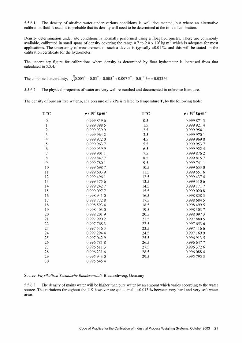
5.5.6.1 The density of air-free water under various conditions is well documented, but where an alternative calibration fluid is used, it is probable that its density will need to be determined at the time of calibration. Density determination under site conditions is normally performed using a float hydrometer. These are commonly available, calibrated in small spans of density covering the range 0.7 to 2.0 x 10³ kg·m-3 which is adequate for most applications. The uncertainty of measurement of such a device is typically ±0.01 %. and this will be stated on the calibration certificate for the hydrometer.
The uncertainty figure for calibrations where density is determined by float hydrometer is increased from that calculated in 5.5.4.
The combined uncertainty, %033.001.05007.0005.003.0003.0 22222
5.5.6.2 The physical properties of water are very well researched and documented in reference literature.
The density of pure air free water ρ, at a pressure of 7 kPa is related to temperature T, by the following table:
T C ρ / 103 kg·m-3 T C ρ / 103 kg·m-3
0 0.999 839 6 0.5 0.999 871 3 1 0.999 898 5 1.5 0.999 921 4 2 0.999 939 9 2.5 0.999 954 1 3 0.999 964 2 3.5 0.999 970 1 4 0.999 972 0 4.5 0.999 969 8 5 0.999 963 7 5.5 0.999 953 7 6 0.999 939 9 6.5 0.999 922 4 7 0.999 901 1 7.5 0.999 876 2 8 0.999 847 7 8.5 0.999 815 7 9 0.999 780 1 9.5 0.999 741 1
10 0.999 698 7 10.5 0.999 653 0 11 0.999 603 9 11.5 0.999 551 6 12 0.999 496 1 12.5 0.999 437 4 13 0.999 375 6 13.5 0.999 310 6 14 0.999 242 7 14.5 0.999 171 7 15 0.999 097 7 15.5 0.999 020 8 16 0.998 941 0 16.5 0.998 858 3 17 0.998 772 8 17.5 0.998 684 5 18 0.998 593 4 18.5 0.998 499 5 19 0.998 403 0 19.5 0.998 303 7 20 0.998 201 9 20.5 0.998 097 3 21 0.997 990 2 21.5 0.997 880 5 22 0.997 768 3 22.5 0.997 653 6 23 0.997 536 3 23.5 0.997 416 6 24 0.997 294 4 24.5 0.997 169 9 25 0.997 042 9 25.5 0.996 913 5 26 0.996 781 8 26.5 0.996 647 7 27 0.996 511 3 27.5 0.996 372 6 28 0.996 231 6 28.5 0.996 088 4 29 0.995 943 0 29.5 0.995 795 3 30 0.995 645 4
Source: Physikalisch Technische Bundesanstalt, Braunschweig, Germany
5.5.6.3 The density of mains water will be higher than pure water by an amount which varies according to the water source. The variations throughout the UK however are quite small; ±0.013 % between very hard and very soft water areas.
Code of Practice for the Calibration of Industrial Process Weighing Systems, October 2003 21
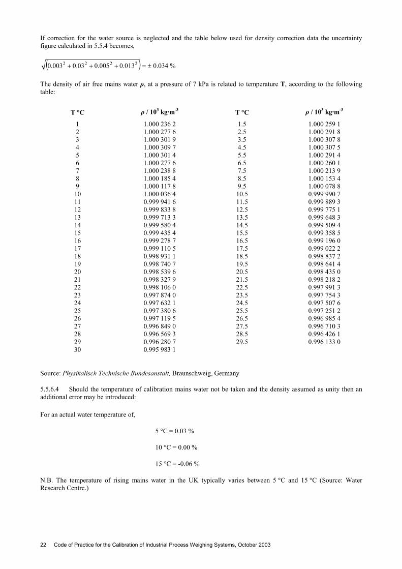
If correction for the water source is neglected and the table below used for density correction data the uncertainty figure calculated in 5.5.4 becomes,
%034.0013.0005.003.0003.0 2222
The density of air free mains water ρ, at a pressure of 7 kPa is related to temperature T, according to the following table:
T C ρ / 103 kg·m-3 T C ρ / 103 kg·m-3
1 1.000 236 2 1.5 1.000 259 1 2 1.000 277 6 2.5 1.000 291 8 3 1.000 301 9 3.5 1.000 307 8 4 1.000 309 7 4.5 1.000 307 5 5 1.000 301 4 5.5 1.000 291 4 6 1.000 277 6 6.5 1.000 260 1 7 1.000 238 8 7.5 1.000 213 9 8 1.000 185 4 8.5 1.000 153 4 9 1.000 117 8 9.5 1.000 078 8
10 1.000 036 4 10.5 0.999 990 7 11 0.999 941 6 11.5 0.999 889 3 12 0.999 833 8 12.5 0.999 775 1 13 0.999 713 3 13.5 0.999 648 3 14 0.999 580 4 14.5 0.999 509 4 15 0.999 435 4 15.5 0.999 358 5 16 0.999 278 7 16.5 0.999 196 0 17 0.999 110 5 17.5 0.999 022 2 18 0.998 931 1 18.5 0.998 837 2 19 0.998 740 7 19.5 0.998 641 4 20 0.998 539 6 20.5 0.998 435 0 21 0.998 327 9 21.5 0.998 218 2 22 0.998 106 0 22.5 0.997 991 3 23 0.997 874 0 23.5 0.997 754 3 24 0.997 632 1 24.5 0.997 507 6 25 0.997 380 6 25.5 0.997 251 2 26 0.997 119 5 26.5 0.996 985 4 27 0.996 849 0 27.5 0.996 710 3 28 0.996 569 3 28.5 0.996 426 1 29 0.996 280 7 29.5 0.996 133 0 30 0.995 983 1
Source: Physikalisch Technische Bundesanstalt, Braunschweig, Germany
5.5.6.4 Should the temperature of calibration mains water not be taken and the density assumed as unity then an additional error may be introduced: For an actual water temperature of,
5 C = 0.03 %
10 C = 0.00 %
15 C = -0.06 %
N.B. The temperature of rising mains water in the UK typically varies between 5 C and 15 C (Source: Water Research Centre.)
22 Code of Practice for the Calibration of Industrial Process Weighing Systems, October 2003
5.6 CALIBRATION PROCEDURE USING PROVING TANKS Clauses 5.6.2 and 5.6.3 are normative.
5.6.1 Introduction This procedure may be used to calibrate systems that can accept and retain a liquid. Calibration by proving tanks within the context of this procedure is restricted to the use of traceable capacity measures using water as the calibration medium.
The method is considered practical for increasing load calibration only and while portable traceable measures with capacities above 100 litres are rare, multiple use of a measure will enable larger vessels to be calibrated.
5.6.2 Specific requirements prior to calibration
5.6.2.1 Before commencing calibration the system and all valves and connections shall be checked for integrity.
5.6.2.2 A source of calibration water shall be available in the required quantities and at a delivery flow rate appropriate to the size of the proving tank.
5.6.2.3 The proving tank should be able to be sited such that its contents can be discharged by gravity directly and unencumbered into the vessel under calibration.
5.6.2.4 The proving tank should be sited at its operating location and primed by filling and emptying once to establish a standard drainage rate.
5.6.2.5 Provision should exist to remove the water from the vessel after each loading procedure. 5.6.3 Calibration Procedure
5.6.3.1 With zero calibration load, check that the weighing system output is stable and record the output.
5.6.3.2 The proving tank shall now be filled to its top datum and the temperature of the water recorded.
5.6.3.3 The contents of the proving tank should now be discharged into the vessel under test for the standard drainage time appearing on its calibration certificate.
5.6.3.4 The output of the weighing system shall be recorded in accordance with subsection 4.4 and having due regard to any turbulence.
5.6.3.5 Repeat steps 5.6.3.2 to 5.6.3.4 until the maximum operating capacity of the weighing system is reached.
5.6.3.6 Steps 5.6.3.1 to 5.6.3.5 should be repeated where required by subsection 4.4, and having due regard for any turbulence.
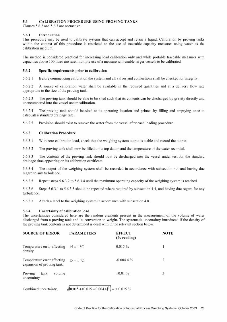
5.6.3.7 Attach a label to the weighing system in accordance with subsection 4.8. 5.6.4 Uncertainty of calibration load The uncertainties considered here are the random elements present in the measurement of the volume of water discharged from a proving tank and its conversion to weight. The systematic uncertainty introduced if the density of the proving tank contents is not determined is dealt with in the relevant section below.
SOURCE OF ERROR PARAMETERS EFFECT (% reading)
NOTE
Temperature error affecting density.
15 ± 1 C 0.015 % 1
Temperature error affecting expansion of proving tank.
15 ± 1 C -0.004 4 % 2
Proving tank volume uncertainty
±0.01 % 3
Combined uncertainty, %015.04004.0015.001.0 22
Code of Practice for the Calibration of Industrial Process Weighing Systems, October 2003 23
Note 1: The density of calibration water is sensitive to temperature. This error is calculated as typical of the change in density that will occur due to the uncertainty of fluid temperature determination. The parameters chosen are examples for water at 15 C and are based on a estimated thermometer reading error combined with an estimate of the possible variation of actual fluid temperature due to uneven mixing of water in the tank. The uncertainty at other reference temperatures will not be dissimilar.
Note 2: The proving tank volume changes with temperature, a correction factor is used to compensate for this change. The parameters chosen are an example for water at 15 C and are based on an estimated thermometer reading error combined with an estimate of the variation of actual fluid temperature and its effect on the tank dimensions throughout its volume.
Note 3: The proving tank volume uncertainty is based on the uncertainty of calibration load for the relevant test method for volume determination.
5.6.5 Correction for Density The conversion of the proving tank volume to weight requires a knowledge of the density of the calibration water. The density of pure mains water is presented in clause 5.5.6.2.
5.6.5.1 If mains water is used, its source neglected and the table in 5.5.6.3 is used for temperature correction data the uncertainty of calibration load calculated in clause 5.6.4 becomes:
%020.0013.04004.0015.001.0 222
5.7 CALIBRATION PROCEDURE USING METHODS REMOTE TO THE OPERATING INSTALLATION
Clauses 5.7.2 and 5.7.3 are normative
5.7.1 Introduction A weighing system may be calibrated out of its normal working installation where it is deemed the effect of the influences associated with the weighing structure (ref. section A1), are negligible or acceptable in its operation. This method is also suitable where a fixed weighing structure is not part of the weighing system, such as, in portable aircraft weighing systems.
This type of calibration is normally carried out in a laboratory where a force standard machine, traceable to national standards, is used to apply loads to the load cells.
5.7.2 Specific requirements prior to calibration The mechanical arrangement of the load cell(s), that is, loading fittings and load distribution on load cells shall be similar as far as practicable, to that of the normal installation. If loading fittings are not provided. the calibration authority may, at their discretion provide suitable fittings. In this case, the authority shall report this in the calibration certificate.
Special attention shall be paid to the actual load distribution on the load cells if the calibration is carried out on the multiple load cell assembly placed in the force standard machine.
The associated signal processor configuration shall be the same as that of the normal operating installation.
The junction box wiring and lengths of cables used shall correspond to the actual operating installation
It is recommended that the temperature of the laboratory environment shall be monitored and reported in the calibration certificate. The method of loading shall be in accordance with subsection 4.4.
5.7.3 Calibration procedure
5.7.3.1 Apply a load to the load cell(s) so that the weighing system output reads zero. This is equal to the zero live load and record the load applied and the system output.
5.7.3.2 Apply a load equal to the sum of the zero live load and maximum operating capacity, and record this output.
5.7.3.3 Repeat steps 5.7.3.1 and 5.7.3.2 until stable readings are obtained.
24 Code of Practice for the Calibration of Industrial Process Weighing Systems, October 2003
5.7.3.4 Compute the difference between the outputs recorded in steps 5.7.3.2 and 5.7.3.1. This represents the output for the weighing range.
5.7.3.5 Apply a load equal to or near as practicable to 20 % of weighing range above the zero live load. Record this output.
5.7.3.6 Repeat 5.7.3.5 for the loads substantially equal to 40, 60, 80 and 100 % of the weighing range. Record the corresponding outputs.
5.7.3.7 Repeat 5.7.3.6 two more times to give three series.
5.7.3.8 Remove the load cells from the force standard machine.
5.7.3.9 Attach a label to the system in accordance with subsection 4.8. 5.7.4 Uncertainty of calibration load The uncertainty of the calibration load is the same as the uncertainty of measurement specified for the force standard machine used to calibrate the weighing system. See WGL9301 for details of force standard machines.
Code of Practice for the Calibration of Industrial Process Weighing Systems, October 2003 25
6 QUALITY OF SERVICE
The testing and calibration operations shall be carried out by organisations operating in accordance with the requirements of ISO Guide 25 : 1990(E) General requirements for competence of calibration and testing laboratories. In the United Kingdom, the competence of the calibration authority is required to be established by a NAMAS (National Accreditation of Measurement and Sampling) accreditation granted by the United Kingdom Accreditation Service (UKAS).
At the time of preparation of this document, no organisation has been NAMAS accredited by UKAS for the site calibration operations described in this Code of Practice. It is therefore proposed the calibration authority as defined in this document shall establish its competence by obtaining accreditation to ISO 9002 : 1994 Quality Systems and have the appropriate Company Operating Procedures installed to formally control the site calibration and test operations.
In the United Kingdom, the quality management of such organisations shall be certified by a Certification Body which has an NACB (National Accreditation of Certification Bodies) accreditation granted by UKAS.
26 Code of Practice for the Calibration of Industrial Process Weighing Systems, October 2003
ANNEX I
A1. GENERAL CONSIDERATIONS
A1.1 INFLUENCE QUANTITIES Prior to the commencement of calibration, it is recommended that the weighing system should be visually inspected for integrity and suitability. Where possible and appropriate this inspection may include the mechanical condition of the vessel such as clearances and any permanent attachments linking the weighing structure to the load bearing structure. The condition of any junction boxes and signal processing components should also be assessed.
Particular consideration should be given to the factors listed below. Where possible these should be quantified or otherwise allowed for or eliminated. Some of the factors may not be present during the calibration but may affect the system when it is in normal operation. Where relevant, the influence quantities may be reported in the calibration certificate.
A1.1.1 Pressure/Vacuum Pressure variations within a weighed vessel may cause significant changes in weighing system output. This may be due to forces induced in flexible pipe couplings. restrictions in breather systems or recorded changes in the mass of gaseous content.
A1.1.2 Temperature
A1.1.2.1 Temperature changes of the components in the measuring chain due to general ambient variations or local heating from auxiliary equipment can affect weighing system output.
A1.1.2.2 Convection currents created by heated jackets or adjacent heat generating equipment can give rise to thermal viscous drag causing changes in weighing system output.
A1.1.2.3 Weight changes of the contents of any heat transfer system attached to the weighing system must be taken into consideration.
A1.1.2.4 Thermal expansion or contraction of the weighing structure or mechanical attachments will affect weighing system output.
A1.1.2.5 Sunlight can cause uneven temperature changes to weighing system components leading to error. A1.1.3 Structural effects
A1.1.3.1 Vibration from agitators, vibrators or other ancillary plant items can cause fluctuating or incorrect outputs.
A1.1.3.2 Deflection or settlement of the load bearing structure can cause measurement errors.
A1.1.3.3 Worn or weak supports such as knife edges can produce an inclined load or movement of the point of support from the design position leading to error.
A1.1.3.4 The output of a weighing system sharing a common load bearing structure with other plant may be affected by interaction.
A1.1.4 Method of loading
A1.1.4.1 Shock loading during operational use can cause displacement of weighing system components which may not be apparent during calibration.
A1.1.4.2 Impact of a load can cause the weighing system to output a higher value than the static figure.
A1.1.4.3 Turbulence of the contents of a load receiving element may cause fluctuations in output.
A1.1.4.4 Consideration should be given to the distribution of the calibration load when this differs from the distribution of the operational load. A1.1.5 Climatic and local effects
A1.1.5.1 Ambient temperature effects are dealt with in Al.1.2.
Code of Practice for the Calibration of Industrial Process Weighing Systems, October 2003 27
A1.1.5.2 Ambient pressure changes can effect the output of pneumatic systems and may also affect electrical systems employing load cells which are not barometrically compensated.
A1.1.5.3 Environmental elements such as snow can form an additional and variable weight.
A1.1.5.4 Wind loads may affect weighing system output.
A1.1.5.5 The possibility of local interference from animal or human causes should be considered during calibration.
A1.1.6 Mechanical effects
A1.1.6.1 Any restriction of movement of the weighing structure will modify the performance of the weighing system. This should be considered when inspecting tie bars and check rods, flexible or rigid pipe connections, couplings, tension wires. walkways. electrical or pneumatic connections and safety measures such as earthing straps.
A1.1.6.2 Friction between the weighing structure and load bearing structure or in corroded or dirty knife edge supports will lead to random errors.
A1.1.6.3 Interaction between the material in the load receiving element and the load bearing or any other external structure can cause errors. This is most likely to occur at or near maximum capacity.
A1.1.7 Radiation and other electrical effects
A1.1.7.1 The weighing system may be effected by high levels of RFI and EMI. The most common source of problem can be radio transmitters used in conjunction with the calibration procedures.
A1.2 PORTABLE WEIGHING SYSTEMS All load cell weighing systems measure forces exerted by a mass which they support. This force is dependent on the value of the acceleration of free fall, g, at the location of use, see annex VI.
Consideration should be given to this effect, and where the variation in the weighing system output due to the change in the g value is considered unacceptable, the weighing system should be calibrated at the location of use.
A1.3 AIR BUOYANCY EFFECT
A1.3.1 The air surrounding a mass exerts an air buoyancy force in the opposite direction to the downward force that the weighing system measures, depending on the volume of air displaced by the mass.
A1.3.2 Consideration should be given to the possible effect of air buoyancy on the calibration of a weighing system when one material is used for calibration and another, of different density, is used during normal weighing operations.
A1.3.3 A typical example is that an error of approximately 0.1 % is introduced when cast iron weights are used to calibrate a system normally weighing material of similar density to water.
This is due to the fact that 1 m3 of cast iron weighing 8 000 kg is uplifted by 1.2 kg, whereas the same weight of water occupies 8 m3 and is uplifted by 9.6 kg.
Air buoyancy correction may be made by using the following equation,
Wtrue = Wind [ ( 1 – da / ds ) / ( 1 – da / dm ) ]
where,
Wtrue is the true weight in the load receiving element Wind is the weight indicated by the weighing system da is the density of air, 1.2 kg·m-3 ds is the density of steel which is generally used to calibrate weighing systems, 8 000 kg·m-3 dm is the density of the weighed object
28 Code of Practice for the Calibration of Industrial Process Weighing Systems, October 2003

Example: A petroleum product having a density of 0.8 × 10³ kg·m-3 is going to be weighed on a weighing system which is calibrated by the use of standard weights. When the load receiving element is filled with the product so that the indicator reads 1 000 kg, the true weight actually in the load receiving element can be obtained from the above expression,
Wtrue = 1 000 [ ( 1 – 1.2 / 8 000 ) / ( 1 – 1.2 / 800 ) ]
= 1 000 × 1.001 352 kg
= 1 001.352 kg
Therefore the actual weight in the vessel is 1 001.352 kg or 0.135 2 % more than indicated since more material is needed to overcome the buoyancy effect.
A1.3.4 Where possible and practicable, the material used for calibration should be of similar density to the operational material.
A1.3.5 The above consideration is not applicable when the calibration is carried out in terms of force.
A1.4 WEIGHING SYSTEM INCORPORATING DUMMY LOAD CELLS OR PIVOTS A1.4.1 The output of a weighing system incorporating dummy load cells is sensitive to the changes of the centre of gravity of the load receiving element. Where possible and practicable, it is recommended that the calibration of such systems is carried out with self levelling materials.
A1.4.2 Where this is not possible, a method of calibration should be selected during which the centre of gravity remains in the same position as that of the weighing system in its normal operation.
A1.5 INFLUENCE OF ZERO TRACKING It is recommended that any zero tracking system be inhibited during calibration.
Code of Practice for the Calibration of Industrial Process Weighing Systems, October 2003 29
ANNEX II
A2. CALIBRATION OF WEIGHING SYSTEM COMPONENTS
The methods detailed below are mainly for establishing the operational integrity of the components of the weighing system and do not take into account the effects of the mechanical influences which may be present in the system. These methods are unlikely to comply with the requirements of BS EN ISO 9000 series entitled ‘Quality management and quality assurance standards’. It is recommended that the user considers the suitability of these methods prior to implementation.
A2.1 USE OF LOAD CELL SIMULATOR Sections A2.1.2 and A2.1.3 are normative.
A2.1.1 Introduction. This method may only be used where it is acceptable to omit the error contributions from the load cells and the influences of their associated mechanical structure. Certain load cell simulators may not be capable of simulating the electrical loading on the signal processor in multiple load cell installations.
This method is only applicable to weighing systems utilising strain gauge type analogue load cells.
A2.1.2 Specific requirements It is important to ensure that the disconnection of the load cells has no adverse effect on the weighing system
Attention should be given to the polarity of the signal in connecting the simulator with reference to tension or compression load application on the load cells.
The simulator should be allowed to stabilise before the commencement of the calibration. Cognisance should be taken of any guidance and recommendations from the manufacturer of the simulator in deciding this stabilisation period.
A2.1.3 Procedure
A2.1.3.1 Ensure that there is no load on the load receiving element, and record the weighing system output.
A2.1.3.2 Remove all existing load cell connections in the junction box.
A2.1.3.3 Connect the load cell simulator in place of the load cell(s). Allow the simulator to stabilise.
A2.1.3.4 Adjust the simulator so that the weighing system output indicates the value recorded in A2.1.3.1. Record the setting or output of the simulator.
A2.1.3.5 Adjust the simulator so that the weighing system output indicates the maximum operating capacity. Record the setting or output of the Simulator.
A2.1.3.6 Repeat the steps in A2.1.3.4 and A2.1.3.5 above until stable readings are obtained for minimum and maximum operating capacity.
A2.1.3.7 Set the simulator to represent 20 % of the maximum operating capacity and record the weighing system output and the simulator setting or output.
A2.1.3.8 Repeat A2.1.3.7 at 20 % intervals up to the maximum operating capacity and record the weighing system output and the corresponding load cell simulator setting or output.
A2.1.3.9 Repeat steps A2.1.3.7 and A2.1.3.8 two more times.
A2.1.3.10 Remove the load cell simulator and replace the load cell connections in the junction box. Allow the system to stabilise. Record the output which should read as noted in A2.1.3.1.
A2.1.3.11 Attach a label to the weighing system in accordance with subsection 4.8 A2.1.4 Guidance on using a load cell simulator Most commercially available load cell simulators are based on the Wheatstone bridge principle. They may incorporate a network of resistors or strain gauges. The output signal is usually adjusted by the use of a thumb wheel switch in millivolt per volt units or the output may be in millivolt units and adjusted by a potentiometer. These units generally simulate a single load cell with the appropriate input and output resistance, typically 350 Ω.
30 Code of Practice for the Calibration of Industrial Process Weighing Systems, October 2003

It is recommended that if the simulator used is not capable of simulating the correct number of load cells in the installation then a suitable resistor network should be used to achieve the required loading.
A2.1.5 Uncertainty of simulated load It is not possible to estimate with reasonable confidence. an uncertainty figure for the complete weighing system calibrated using this method. It is recommended that the manufacturers’ stated accuracy or uncertainty for the load cell simulator should be used as a basis to estimate the uncertainty of the signal applied to the weighing system.
A2.2 USE OF MILLIVOLT SOURCE A2.2.1 Introduction This method is only applicable to weighing systems utilising strain gauge type analogue load cells.
This method should only be used where it is acceptable to ignore the error contributions from the load cells and the influences of their associated mechanical structure. The use of a millivolt source is considered only appropriate in weighing systems where dc excitation voltage is used.
A2.2.2 Specific requirements It is important to ensure that the disconnection of the signal wires of the load cells has no adverse effect on the weighing system. Attention should be paid especially to those systems utilising six wire sense circuitry.
Attention should be given to the polarity of the signal in connecting the millivolt source with reference to tension or compression load application on the load cells. The millivolt simulator should be allowed to stabilise before the commencement of the calibration. Cognisance should be taken of the guidance and recommendations from the manufacturers of the millivolt source in deciding this stabilisation period.
A2.2.3 Procedure
A2.2.3.1 Ensure that there is no load on the load receiving element, and record the weighing system output.
A2.2.3.2 Remove only the load cell signal leads in the junction box.
A2.2.3.3 Connect the millivolt source in place of the load cell signal leads. Allow the millivolt source to stabilise.
A2.2.3.4 Adjust the millivolt source so that the weighing system output indicates the output recorded in A2.2.3.1. Record the output of the millivolt source.
A2.2.3.5 Adjust the millivolt source so that the weighing system output indicates the maximum operating capacity. Record the output of the mV source.
A2.2.3.6 Set the millivolt source to represent 20 % of the maximum operating capacity and record the weighing system output and millivolt source output.
A2.2.3.7 Repeat the step A2.2.3.6 at 20 % intervals up to the maximum operating capacity and record the weighing system output and the corresponding millivolt source output.
A2.2.3.8 Repeat steps A2.2.3.6 and A2.2.3.7 where required by subsection 4.4.
A2.2.3.9 Remove the millivolt source and replace the load cell signal leads in the junction box. Allow the system to stabilise. The weighing system output should read as noted in A2.2.3.1.
A2.2.3.10 Attach a label to the weighing system in accordance with subsection 4.8 A2.2.4 Uncertainty of simulated load It is recommended that the manufacturers’ stated accuracy or uncertainty of measurement for the millivolt source should be used as a basis to estimate the uncertainty of the signal applied to the weighing system.
A2.3 USE OF SHUNT RESISTORS A2.3.1 Introduction This method may only be used where it is acceptable to ignore the error contributions from inappropriate mechanical application of load to the load cells and the influence of the associated mechanical structure.
Code of Practice for the Calibration of Industrial Process Weighing Systems, October 2003 31
The procedure depends on manufacturers’ data being available, which define the measured output of a particular load cell when a resistor of specified value is connected in parallel (shunted), to one branch of the strain gauge bridge. The output will be stated as equal to that which would have been produced by a force of equal magnitude.
The output data is related to the resistance of the load cell and its connecting cables. The connections may differ from those given by the manufacturer which appear on the load cell calibration certificate. Any modifications must be taken into account when evaluating data.
Normally one shunt calibration resistor is used.
The information obtained can also be used to perform subsequent spot checks to confirm the weighing system performance.
A2.3.2 Specific requirements prior to calibration Cognisance should be taken of the guidance and recommendations provided by the load cell manufacturer for any shunt calibration data that may be provided for the system.
A2.3.3 Procedure
A2.3.3.1 Ensure that there is no load on the load receiving element, and record the weighing system output.
A2.3.3.2 Connect the shunt calibration resistor across one arm of the strain gauge bridge in the manner recommended by the manufacturer. (This may be achieved by push button actuation of the shunt calibration facility in a proprietary signal processor).
A2.3.3.3 Record the weighing system output in accordance with subsection 4.4.
A2.3.3.4 Repeat steps A2.3.3.1 to A2.3.3.3 two more times.
A2.3.3.5 Attach a label to the weighing system in accordance with subsection 4.8. A2.3.4 Guidance on using shunt calibration resistors
A2.3.4.1 Uncertainty of simulated load It is not possible to estimate with reasonable confidence, an uncertainty figure for the complete weighing system calibrated using this method. It is recommended that the manufacturer’s stated uncertainty for the shunt calibration data to be used as a basis to estimate the uncertainty of the signal applied to the weighing system.
A2.3.4.2 Load cell cable The shunt calibration figure provided by the manufacturer will relate to a transducer with its original length (or a specified length) of connection cable intact. This cable should not normally cut or extended without prior reference to the manufacturer.
The shunt calibration figures will also be modified in multiple load cell systems and where additional interconnecting cable is used.
A2.4 USE OF THEORETICAL CALCULATIONS Clauses A2.4.2 and A2.4.3 are normative.
A2.4.1 Introduction This method may only be used where it is acceptable to ignore the error contributions from inappropriate mechanical application of load to the load cells and the influence of the associated mechanical structure.
The viability of this method depends on the availability of a full certificate of performance, see WGL9301, and calibration certificate for the individual load cells, the associated signal processor and other elements of the measuring chain as appropriate.
The data presented in the calibration certificate for the weighing system is obtained by combining data given in individual calibration certificates of the load cells and the signal processor at selected load points. This may involve interpolation of data in order to obtain common loading points on the load cells and the signal processor. The interpolation of data is acceptable, however extrapolation of data is not permitted
32 Code of Practice for the Calibration of Industrial Process Weighing Systems, October 2003
A2.4.2 Specific requirements It is important that the operating conditions of the weighing system shall be established detailing all the relevant parameters such as dead load, weighing range, gross weight and maximum operating capacity. The performance certificates or calibration certificates for the load cells and signal processor shall be available and these certificates shall comply with the traceability requirements given in subsection 4.3.
In the case of multiple load cell weighing systems, the distribution of load on load cells shall be considered.
A2.4.3 Procedure
A2.4.3.1 Select not less than five substantially equal loads. covering the weighing range, to obtain the calibration data.
A2.4.3.2 Compute the combined outputs of the load cells at each of these selected loads for increasing and if required for decreasing loads.
A2.4.3.3 Compute the signal processor output for the combined load cell outputs.
A2.4.3.4 Report the selected loads and the corresponding computed signal processor output in the calibration certificate.
A2.4.3.5 Attach a label to the weighing system in accordance with subsection 4.8. A2.4.4 Guidance on the method of combining calibration data In a typical weighing system a number of load cells are connected in parallel in a junction box or at the input of the signal processor. The resultant combined signal at this point may be expressed by the following equation,
n
i i
n
i i
i
o
R
Re
e
1
1
1
where,
eo is the combined open circuit output ei is the output voltage of the individual load cell Ri is the output resistance of the individual load cell n is the number of load cells connected in parallel
The above equation may be used to obtain the combined output for several loads.
A2.4.5 Uncertainty of calibration load Uncertainty of combined calibration load is the root mean square of the uncertainty of the load applied to the individual load cells when calibrated.
A2.5 REVALIDATION OF LEVER SYSTEMS A2.5.1 Introduction This method may be used as a revalidation check of a lever operated weighing system which incorporates a single load cell and where it is acceptable to disregard the error contributions from the mechanical construction of the weighing system.
The procedure depends on the provision, usually by the manufacturer, of a defined location and method of applying a known test load to the lever system or directly to the load cell. It is important that the load is applied in the same direction as the normal operating loads.
The test load may be standard weights, reference weights or a combination of these.
Code of Practice for the Calibration of Industrial Process Weighing Systems, October 2003 33

A2.5.2 Specific requirements Cognisance should be taken of guidance and recommendations provided by the weighing system manufacturer for any data which may be provided on the operation of levers or method of applying load to the associated load cell.
There shall be a clearly defined location for the application of test load. The value of this test load shall have been specified.
The test load and if relevant its associated hangers, platforms etc., shall comply with the traceability requirements given in subsection 4.3.
A2.5.3 Procedure
A2.5.3.1 Ensure that there is no load on the load receiving element and record the weighing system output.
A2.5.3.2 Apply the test load to the specified location and record the weighing system output in accordance with subsection 4.4.
A2.5.3.3 Remove the load and repeat A2.5.3.1 and A2.5.3.2 two more times.
A2.5.3.4 Attach a label to the weighing system in accordance with subsection 4.8. A2.5.4 Uncertainty of applied load The uncertainty of standard weights shall be calculated on the basis given in 5.1.4.
The uncertainty of reference weights shall be calculated on the basis given in 5.2.4.
There may be additional uncertainties due to perturbation of the load measured by the load cell, caused by mechanics of the lever system, or inherent in the application of this method. Cognisance should be taken of the manufacturers’ information in this respect.
34 Code of Practice for the Calibration of Industrial Process Weighing Systems, October 2003
ANNEX III
A3. PROCESSING OF CALIBRATION DATA
For the purpose of computing data in this section the term ‘weighing system output’ shall assume the value of the difference between output at the calibration load and the output at zero live load of each calibration test.
A3.1 Calculation of non-linearity using the best straight line method A3.1.1 Calculate, where applicable, the average values of weighing system output for increasing loads only, for each calibration load applied. A3.1.2 Compute a ‘best fit’ straight line passing through zero, relating the weighing system output to the load applied, by the method of least squares using the expression;
2i
ii
L
RLm
where,
m is the slope of the best fit straight line Li is the load applied Ri is the weighing system output corresponding to load Li
A3.1.3 For each calibration load. calculate the differences between the actual weighing system output and the value computed from the best straight line. The non-linearity is the difference expressed as a percentage of span. A3.2 Calculation of non-linearity using the terminal line method A3.2.1 Calculate, where applicable. the average values of weighing system output for increasing loads only, for each calibration load applied. A3.2.2 For each calibration load, compute the weighing system output from the terminal line for each calibration load applied. A3.2.3 For each calibration load, calculate the differences between actual weighing system output and the value computed from the terminal line. The non-linearity is the difference expressed as a percentage of span. A3.3 Calculation of non-linearity (decreasing) using the best straight line method This is an identical calculation to that in A3.1 above but using data for decreasing loads only.
A3.4 Calculation of non-linearity (decreasing) using the terminal line method This is an identical calculation to that in A3.2 above but using data for decreasing loads only.
A3.5 Calculation of hysteresis A3.5.1 Calculate, where applicable. the average values of weighing system output for each increasing and decreasing calibration load applied. A3.5.2 For each calibration load, calculate the difference between the weighing system output for increasing load and decreasing load. The hysteresis is the difference, expressed as a percentage of span. A3.6 Calculation of combined error, using the best straight line method The combined error here includes repeatability.
A3.6.1 Calculate, where applicable, the average values of weighing system output for each increasing and decreasing calibration load applied. A3.6.2 Compute a ‘best fit’ straight line passing through zero, relating the weighing system output to the load applied, by the method of least squares using the expression given in A3.1.2.
Code of Practice for the Calibration of Industrial Process Weighing Systems, October 2003 35
A3.6.3 For each calibration load, both increasing and decreasing, calculate the maximum difference between the actual weighing system output and the value computed from the best straight line. The combined error is the maximum of these differences expressed as ± percentage of span. A3.7 Calculation of combined error, using the terminal line method The combined error here includes repeatability A3.7.1 Calculate. where applicable, the average values of weighing system output for each calibration load applied. A3.7.2 For each calibration load, both increasing and decreasing, the weighing system output corresponding to a straight line passing through zero load and maximum load applied is calculated. A3.7.3 For each calibration load, both increasing and decreasing, calculate the maximum difference between the actual weighing system output and the value computed from the straight line. The combined error is the maximum of these differences expressed as ± percentage of span. A3.8 Calculation of repeatability A3.8.1 Calculate the maximum difference between the three weighing system outputs taken at each repeated calibration load for increasing and, if measured, decreasing loads. A3.8.2 The repeatability is the maximum of these calculated values expressed as a percentage of span at this load.
36 Code of Practice for the Calibration of Industrial Process Weighing Systems, October 2003
ANNEX IV
A4. TEST PROCEDURES AND PROCESSING OF TEST DATA
These test procedures may also have relevance as additional tests that can be performed in conjunction with calibration procedures in this Code of Practice.
A4.1 Determination of eccentric loading effects A4.1.1 The weighing structure may be loaded during normal operations or during calibration in an asymmetric way relative to the geometry of the load cell supports. The output of the weighing system may be in error due to an imbalance of contribution to the total output made by each load cell or other physical causes. The magnitude of these errors can be determined by the following test procedure. A4.1.2 Divide the loading area into the same number of substantially equal segments as the weigh structure has supports. The segments should be as near as practicable symmetric to the support. A4.1.3 With zero calibration load check that the weighing system output is stable and then record the output. A4.1.4 Place a test load of value, as near as possible, to that shown below, within each segment. in accordance with subsection 4.4 and record the output.
Number of supports (n) Test load Maximum operating capacity (Note 1)
1 1/3 (Note 2) 2 1/3 3 1/3 4 1/3
n > 4 1/(n-1) Note 1: A load receiving element subject to minimal off-centre loading during normal operation may be tested with a test load of 1/10 of the maximum operating capacity.
Note 2: A load receiving element supported by a single load cell should be tested by placing the test load at selected positions on the load receptor. The locations chosen should be recorded.
A4.1.5 Repeat steps A4.1.3 and A4.1.4 two more times to give three series. A4.2 Calculation of eccentric loading effects A4.2.1 Calculate the average value of weighing system output for each eccentric load applied. A4.2.2 Calculate the overall average value of weighing system output for all the eccentric loads applied. A4.2.3 Compute the maximum difference between the average value for each eccentric load and the overall average and express this difference as a percentage of the overall average. A4.3 Determination of incremental error For some applications, notably batch weighing, where small additions are to be made to or from a large batch , a knowledge of incremental error is advantageous. For this determination to be useful the resolution of the weighing system should be smaller than the expected error.
A4.3.1 Tests to determine incremental error may be performed during the calibration procedure, providing due consideration is given to subsection 4.4. A4.3.2 At selected loads place a small additional test load in accordance with subsection 4.4, nominally centred on the weighing structure. The value of this load should be appropriate to the normal operating conditions. Record the weighing system output before and after load application. Remove the test load. A4.3.3 Repeat the test two more times to give three series.
Code of Practice for the Calibration of Industrial Process Weighing Systems, October 2003 37
A4.4 Calculation of incremental error A4.4.1 Calculate the average value of weighing system output change for each incremental load applied. A4.4.2 Compute the difference between this value and the value of the load change and express this difference either in absolute weight terms or as a percentage of the incremental load applied.
38 Code of Practice for the Calibration of Industrial Process Weighing Systems, October 2003
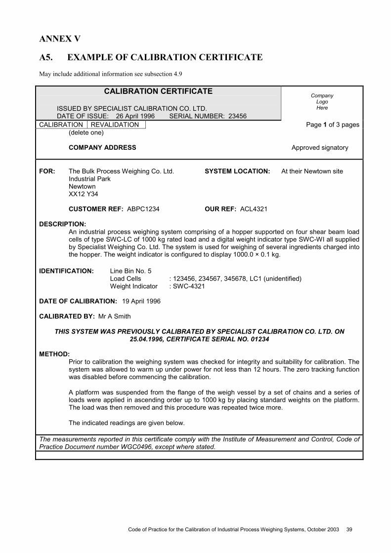
ANNEX V
A5. EXAMPLE OF CALIBRATION CERTIFICATE
May include additional information see subsection 4.9
CALIBRATION CERTIFICATE ISSUED BY SPECIALIST CALIBRATION CO. LTD. DATE OF ISSUE: 26 April 1996 SERIAL NUMBER: 23456
Company
Logo Here
CALIBRATION REVALIDATION Page 1 of 3 pages (delete one) COMPANY ADDRESS Approved signatory FOR: The Bulk Process Weighing Co. Ltd. SYSTEM LOCATION: At their Newtown site Industrial Park Newtown XX12 Y34 CUSTOMER REF: ABPC1234 OUR REF: ACL4321 DESCRIPTION: An industrial process weighing system comprising of a hopper supported on four shear beam load
cells of type SWC-LC of 1000 kg rated load and a digital weight indicator type SWC-WI all supplied by Specialist Weighing Co. Ltd. The system is used for weighing of several ingredients charged into the hopper. The weight indicator is configured to display 1000.0 × 0.1 kg.
IDENTIFICATION: Line Bin No. 5 Load Cells : 123456, 234567, 345678, LC1 (unidentified) Weight Indicator : SWC-4321 DATE OF CALIBRATION: 19 April 1996 CALIBRATED BY: Mr A Smith
THIS SYSTEM WAS PREVIOUSLY CALIBRATED BY SPECIALIST CALIBRATION CO. LTD. ON 25.04.1996, CERTIFICATE SERIAL NO. 01234
METHOD: Prior to calibration the weighing system was checked for integrity and suitability for calibration. The
system was allowed to warm up under power for not less than 12 hours. The zero tracking function was disabled before commencing the calibration.
A platform was suspended from the flange of the weigh vessel by a set of chains and a series of loads were applied in ascending order up to 1000 kg by placing standard weights on the platform. The load was then removed and this procedure was repeated twice more.
The indicated readings are given below.
The measurements reported in this certificate comply with the Institute of Measurement and Control, Code of Practice Document number WGC0496, except where stated.
Code of Practice for the Calibration of Industrial Process Weighing Systems, October 2003 39

ANNEX V
A5. EXAMPLE OF CALIBRATION CERTIFICATE (continued) May include additional information see subsection 4.9
CALIBRATION CERTIFICATE ISSUED BY SPECIALIST CALIBRATION CO. LTD.
Serial Number 23456
Page 2 of 3 pages
TRACEABILITY:
Platform identification no. 949, calibration certificate no.TR6005, calibrated with weighing system having NAMAS calibration certificate no. 00199.
Set of chains identification no. 940, calibration certificate no. TO5934, calibrated on a weigh scale having NAMAS calibration certificate no. 19909.
Standard weights, NAMAS calibration certificate numbers TO3438, TO3439, TO3440 and TO3460 to M1 grade, O.I.M.L. International Recommendation R111.
RESULTS: a. The calibration results reported below are ‘as found’. No adjustment has been carried out on the weighing system output.
Table 1 Recorded results.
LOAD APPLIED LOAD DISPLAYED kg kg Test 1 Test 2 Test 3 0 0.0 0.1 0.1 125 (chains) 125.4 125.2 125.6 325 (+ platform) 325.2 325.5 325.6 400 400.3 400.5 400.8 600 600.8 600.6 600.9 800 800.3 800.5 800.3 1 000 1 000.5 1 000.6 1 000.5 0 0.2 0.1 0.1
Table 2
Calculated differences of output after correction for zero load output.
LOAD APPLIED DIFFERENCES OF OUTPUT kg kg Test 1 Test 2 Test 3 Average 125 (chains) 125.4 125.1 125.5 125.3 325 (+ platform) 325.2 325.4 325.5 325.4 400 400.3 400.4 400.7 400.5 600 600.8 600.5 600.8 600.7 800 800.3 800.4 800.2 800.3 1 000 1 000.5 1 000.5 1 000.4 1 000.5 Checked
The measurements reported in this certificate comply with the Institute of Measurement and Control, Code of Practice Document number WGC0496, except where stated.
40 Code of Practice for the Calibration of Industrial Process Weighing Systems, October 2003
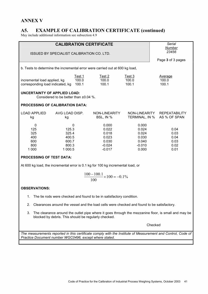
ANNEX V
A5. EXAMPLE OF CALIBRATION CERTIFICATE (continued) May include additional information see subsection 4.9
CALIBRATION CERTIFICATE ISSUED BY SPECIALIST CALIBRATION CO. LTD.
Serial Number 23456
Page 3 of 3 pages
b. Tests to determine the incremental error were carried out at 600 kg load, Test 1 Test 2 Test 3 Average incremental load applied, kg 100.0 100.0 100.0 100.0 corresponding load indicated, kg 100.1 100.1 100.1 100.1 UNCERTAINTY OF APPLIED LOAD: Considered to be better than ±0.04 %.
PROCESSING OF CALIBRATION DATA: LOAD APPLIED AVG LOAD DISP. NON-LINEARITY NON-LINEARITY REPEATABILITY kg kg BSL, IN % TERMINAL, IN % AS % OF SPAN 0 0 0.000 0.000 125 125.3 0.022 0.024 0.04 325 325.4 0.018 0.024 0.03 400 400.5 0.023 0.030 0.04 600 600.7 0.030 0.040 0.03 800 800.3 -0.024 -0.010 0.02 1 000 1 000.5 -0.017 0.000 0.01 PROCESSING OF TEST DATA: At 600 kg load, the incremental error is 0.1 kg for 100 kg incremental load, or
%1.0100100
1.100100
OBSERVATIONS:
1. The tie rods were checked and found to be in satisfactory condition.
2. Clearances around the vessel and the load cells were checked and found to be satisfactory.
3. The clearance around the outlet pipe where it goes through the mezzanine floor, is small and may be blocked by debris. This should be regularly checked.
Checked
The measurements reported in this certificate comply with the Institute of Measurement and Control, Code of Practice Document number WGC0496, except where stated.
Code of Practice for the Calibration of Industrial Process Weighing Systems, October 2003 41
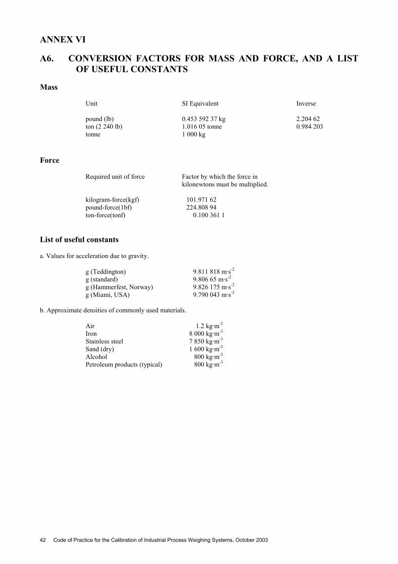
ANNEX VI
A6. CONVERSION FACTORS FOR MASS AND FORCE, AND A LIST OF USEFUL CONSTANTS
Mass
Unit
SI Equivalent Inverse
pound (lb) 0.453 592 37 kg 2.204 62 ton (2 240 lb) 1.016 05 tonne 0.984 203 tonne 1 000 kg
Force
Required unit of force Factor by which the force in kilonewtons must be multiplied.
kilogram-force(kgf) 101.971 62 pound-force(1bf) 224.808 94 ton-force(tonf) 0.100 361 1
List of useful constants
a. Values for acceleration due to gravity.
g (Teddington) 9.811 818 m·s-2 g (standard) 9.806 65 m·s-2 g (Hammerfest, Norway) 9.826 175 m·s-2 g (Miami, USA) 9.790 043 m·s-2
b. Approximate densities of commonly used materials.
Air 1.2 kg·m-3
Iron 8 000 kg·m-3
Stainless steel 7 850 kg·m-3
Sand (dry) 1 600 kg·m-3
Alcohol 800 kg·m-3
Petroleum products (typical) 800 kg·m-3
42 Code of Practice for the Calibration of Industrial Process Weighing Systems, October 2003
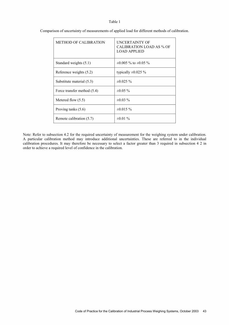
Table 1
Comparison of uncertainty of measurements of applied load for different methods of calibration.
METHOD OF CALIBRATION UNCERTAINTY OF CALIBRATION LOAD AS % OF LOAD APPLIED
Standard weights (5.1) ±0.005 % to ±0.05 %
Reference weights (5.2) typically ±0.025 %
Substitute material (5.3) ±0.025 %
Force transfer method (5.4) ±0.05 %
Metered flow (5.5) ±0.03 %
Proving tanks (5.6) ±0.015 %
Remote calibration (5.7) ±0.01 %
Note: Refer to subsection 4.2 for the required uncertainty of measurement for the weighing system under calibration. A particular calibration method may introduce additional uncertainties. These are referred to in the individual calibration procedures. It may therefore be necessary to select a factor greater than 3 required in subsection 4 2 in order to achieve a required level of confidence in the calibration.
Code of Practice for the Calibration of Industrial Process Weighing Systems, October 2003 43
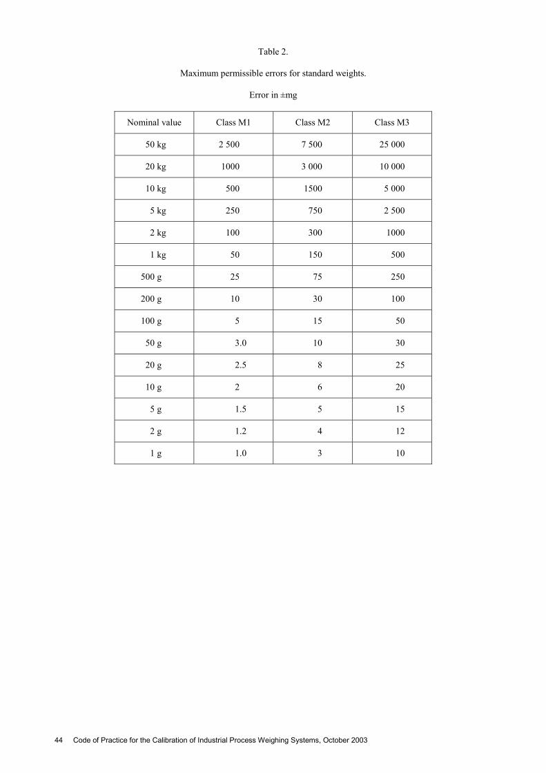
Table 2.
Maximum permissible errors for standard weights.
Error in ±mg
Nominal value Class M1 Class M2 Class M3
50 kg 2 500 7 500 25 000
20 kg 1000 3 000 10 000
10 kg 500 1500 5 000
5 kg 250 750 2 500
2 kg 100 300 1000
1 kg 50 150 500
500 g 25 75 250
200 g 10 30 100
100 g 5 15 50
50 g 3.0 10 30
20 g 2.5 8 25
10 g 2 6 20
5 g 1.5 5 15
2 g 1.2 4 12
1 g 1.0 3 10
44 Code of Practice for the Calibration of Industrial Process Weighing Systems, October 2003
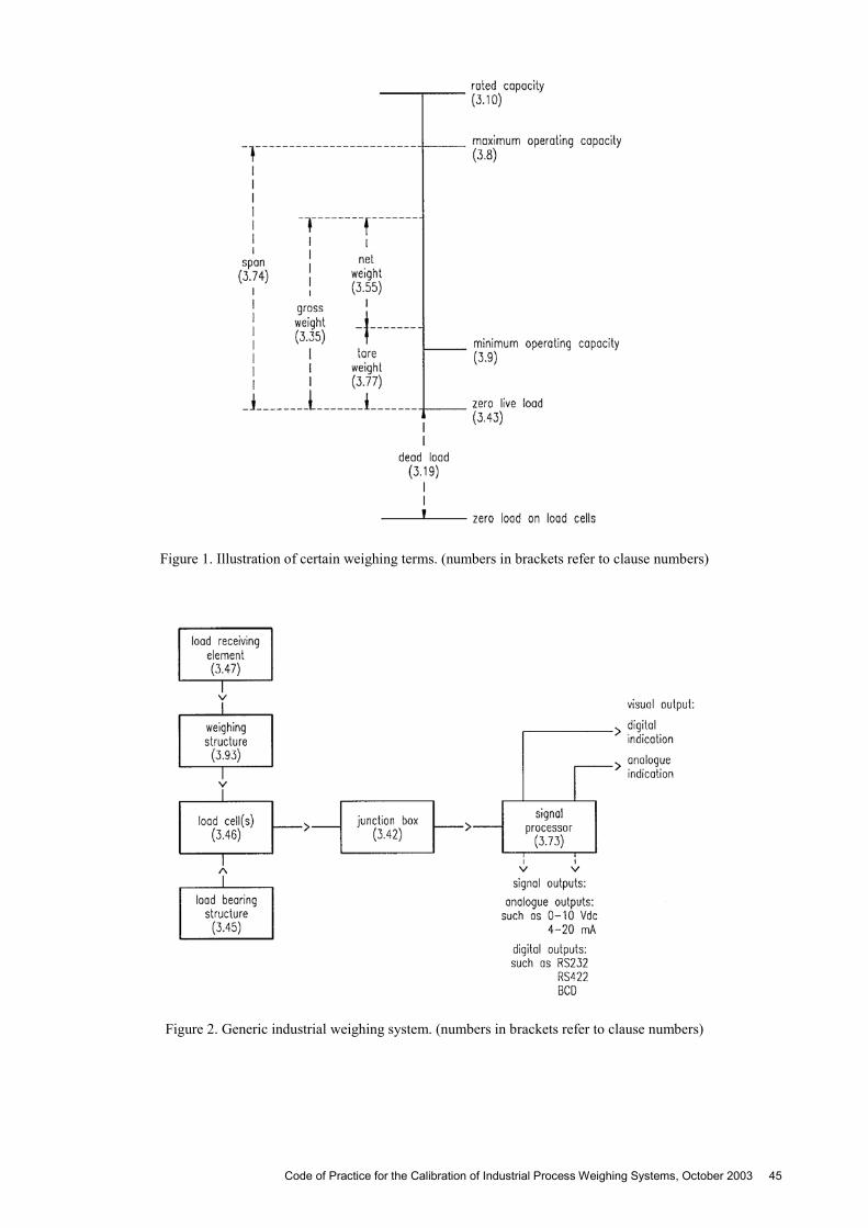
Figure 1. Illustration of certain weighing terms. (numbers in brackets refer to clause numbers)
Figure 2. Generic industrial weighing system. (numbers in brackets refer to clause numbers)
Code of Practice for the Calibration of Industrial Process Weighing Systems, October 2003 45
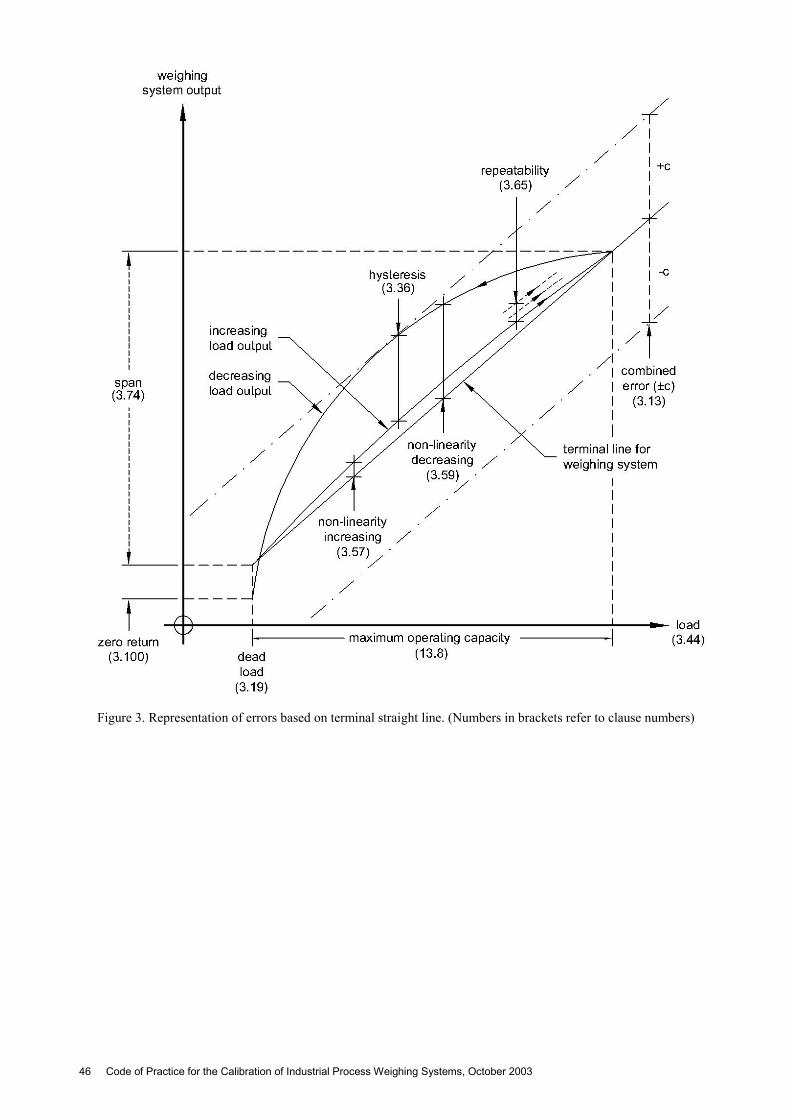
Figure 3. Representation of errors based on terminal straight line. (Numbers in brackets refer to clause numbers)
46 Code of Practice for the Calibration of Industrial Process Weighing Systems, October 2003
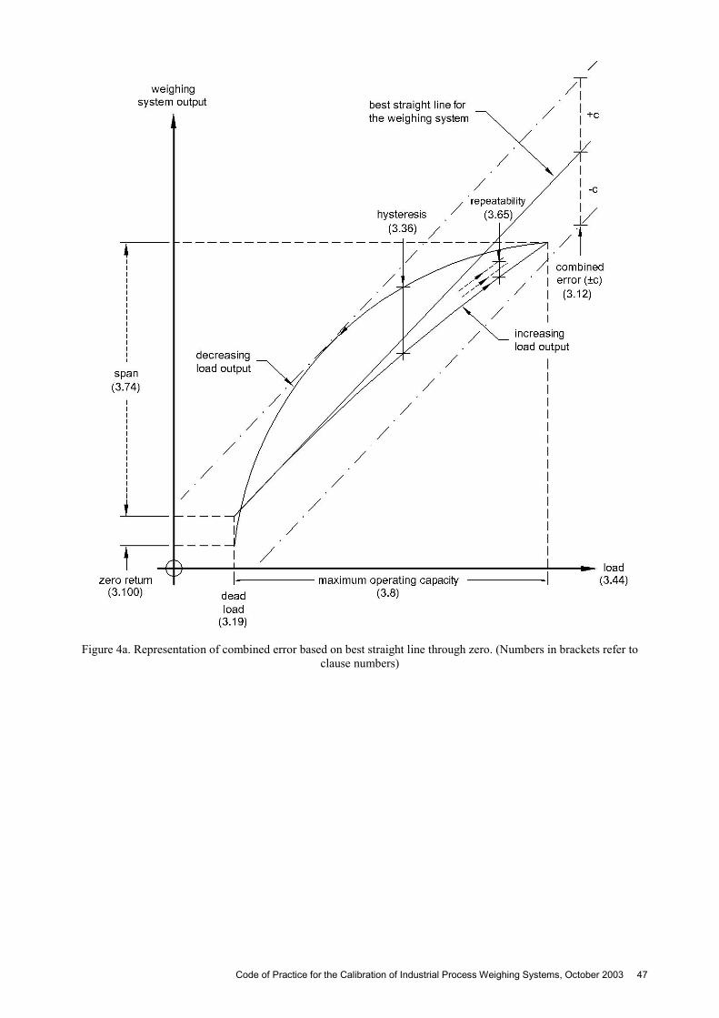
Figure 4a. Representation of combined error based on best straight line through zero. (Numbers in brackets refer to clause numbers)
Code of Practice for the Calibration of Industrial Process Weighing Systems, October 2003 47
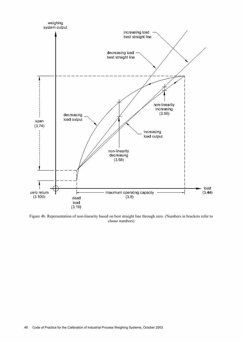
Figure 4b. Representation of non-linearity based on best straight line through zero. (Numbers in brackets refer to clause numbers)
48 Code of Practice for the Calibration of Industrial Process Weighing Systems, October 2003
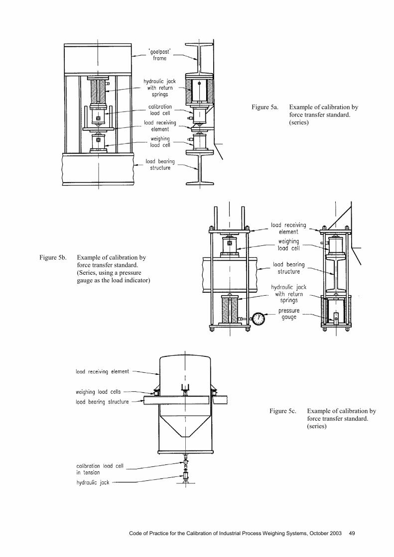
Figure 5a. Example of calibration by force transfer standard. (series)
Figure 5b. Example of calibration by force transfer standard. (Series, using a pressure gauge as the load indicator)
Figure 5c. Example of calibration by force transfer standard. (series)
Code of Practice for the Calibration of Industrial Process Weighing Systems, October 2003 49
Figure 6. Example of calibration by force transfer standard. (parallel)
Figure 7. Calibration by flow meter - general arrangement
50 Code of Practice for the Calibration of Industrial Process Weighing Systems, October 2003
Code of Practice for the Calibration of Industrial Process Weighing Systems, October 2003 51
BIBLIOGRAPHY
1. BS EN 30012-1 : 1993 Quality assurance requirements for measuring equipment. Part 1. Metrological confirmation system for measuring equipment.
2. O.I.M.L. International Recommendation R111, Weights of classes El , E2, F1, F2, M1, M2, M3. Edition 1994(E)
3. BS 5233 : 1986 (1993) Glossary of terms used in metrology (incorporating BS 2643).
4. WGL9301 : A procedure for calibration and testing of strain gauge load cells for industrial process weighing and force measurement. Institute of Measurement and Control, London, 1993.
5. O.I.M.L. International Recommendation No.33, 1979, Conventional value of the result of weighing in air.
6. O.I.M.L. International Recommendation No.47, 1976, Standard weights for testing of high capacity weighing machines.
7. BS EN 45501 : 1994 Metrological aspects of non-automatic weighing instruments.
8. NIS 6 Calibration of weighing machines and weights, NAMAS, July 1992.
9. Guide to the Expression of Uncertainty in Measurement, International Organisation for Standardisation, 1993.
Related Documents