Wireless Pers Commun DOI 10.1007/s11277-011-0380-x A Clean Slate Architecture Design for VANETs Mari Carmen Domingo · Angélica Reyes © Springer Science+Business Media, LLC. 2011 Abstract In this paper, VANET applications have been classified according to their pur- pose. Furthermore, a clean-slate architecture specifically designed for VANETs has been introduced. The proposed non-layered context-aware ubiquitous architecture adapts dynam- ically to changes, is oriented to services (VANET applications) and has a flexible structure. The vehicle and environmental context-aware information as well as the VANET communi- cation characteristics are designed for the proper operation of the applications. In addition, the performance of Automatic Repeat Request and Forward Error Correction (FEC) block codes with respect to the throughput efficiency has also been analyzed for a VANET fol- lowing the proposed clean-slate architecture. The numerical results show that the proposed clean-slate architecture outperforms the traditional layered architecture with respect to the throughput efficiency for both error control schemes. FEC block codes are able to maintain high throughput efficiency over longer distances because the hop length extension technique is applied. Keywords VANETs · Clean-slate architecture · Applications · Context-aware information 1 Introduction Ad Hoc Networks are formed by mobile devices that are able to transmit without hav- ing to resort to a pre-existing network infrastructure. In an ad-hoc network, terminals can M. C. Domingo (B ) Electrical Engineering Department, UPC-Barcelona Tech University, Esteve Terrades, 7, 08860 Castelldefels, Barcelona, Spain e-mail: [email protected] A. Reyes Computer Architecture Department, UPC-Barcelona Tech University, Esteve Terrades, 7, 08860 Castelldefels, Barcelona, Spain e-mail: [email protected] 123

Welcome message from author
This document is posted to help you gain knowledge. Please leave a comment to let me know what you think about it! Share it to your friends and learn new things together.
Transcript
Wireless Pers CommunDOI 10.1007/s11277-011-0380-x
A Clean Slate Architecture Design for VANETs
Mari Carmen Domingo · Angélica Reyes
© Springer Science+Business Media, LLC. 2011
Abstract In this paper, VANET applications have been classified according to their pur-pose. Furthermore, a clean-slate architecture specifically designed for VANETs has beenintroduced. The proposed non-layered context-aware ubiquitous architecture adapts dynam-ically to changes, is oriented to services (VANET applications) and has a flexible structure.The vehicle and environmental context-aware information as well as the VANET communi-cation characteristics are designed for the proper operation of the applications. In addition,the performance of Automatic Repeat Request and Forward Error Correction (FEC) blockcodes with respect to the throughput efficiency has also been analyzed for a VANET fol-lowing the proposed clean-slate architecture. The numerical results show that the proposedclean-slate architecture outperforms the traditional layered architecture with respect to thethroughput efficiency for both error control schemes. FEC block codes are able to maintainhigh throughput efficiency over longer distances because the hop length extension techniqueis applied.
Keywords VANETs · Clean-slate architecture · Applications · Context-aware information
1 Introduction
Ad Hoc Networks are formed by mobile devices that are able to transmit without hav-ing to resort to a pre-existing network infrastructure. In an ad-hoc network, terminals can
M. C. Domingo (B)Electrical Engineering Department, UPC-Barcelona Tech University, Esteve Terrades, 7,08860 Castelldefels, Barcelona, Spaine-mail: [email protected]
A. ReyesComputer Architecture Department, UPC-Barcelona Tech University, Esteve Terrades, 7,08860 Castelldefels, Barcelona, Spaine-mail: [email protected]
123
M. C. Domingo, A. Reyes
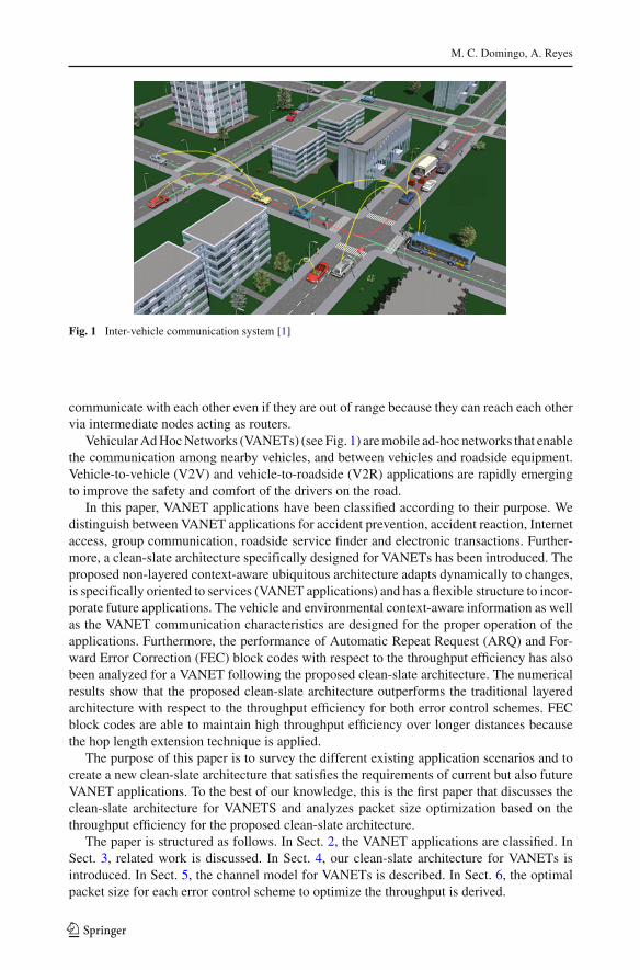
Fig. 1 Inter-vehicle communication system [1]
communicate with each other even if they are out of range because they can reach each othervia intermediate nodes acting as routers.
Vehicular Ad Hoc Networks (VANETs) (see Fig. 1) are mobile ad-hoc networks that enablethe communication among nearby vehicles, and between vehicles and roadside equipment.Vehicle-to-vehicle (V2V) and vehicle-to-roadside (V2R) applications are rapidly emergingto improve the safety and comfort of the drivers on the road.
In this paper, VANET applications have been classified according to their purpose. Wedistinguish between VANET applications for accident prevention, accident reaction, Internetaccess, group communication, roadside service finder and electronic transactions. Further-more, a clean-slate architecture specifically designed for VANETs has been introduced. Theproposed non-layered context-aware ubiquitous architecture adapts dynamically to changes,is specifically oriented to services (VANET applications) and has a flexible structure to incor-porate future applications. The vehicle and environmental context-aware information as wellas the VANET communication characteristics are designed for the proper operation of theapplications. Furthermore, the performance of Automatic Repeat Request (ARQ) and For-ward Error Correction (FEC) block codes with respect to the throughput efficiency has alsobeen analyzed for a VANET following the proposed clean-slate architecture. The numericalresults show that the proposed clean-slate architecture outperforms the traditional layeredarchitecture with respect to the throughput efficiency for both error control schemes. FECblock codes are able to maintain high throughput efficiency over longer distances becausethe hop length extension technique is applied.
The purpose of this paper is to survey the different existing application scenarios and tocreate a new clean-slate architecture that satisfies the requirements of current but also futureVANET applications. To the best of our knowledge, this is the first paper that discusses theclean-slate architecture for VANETS and analyzes packet size optimization based on thethroughput efficiency for the proposed clean-slate architecture.
The paper is structured as follows. In Sect. 2, the VANET applications are classified. InSect. 3, related work is discussed. In Sect. 4, our clean-slate architecture for VANETs isintroduced. In Sect. 5, the channel model for VANETs is described. In Sect. 6, the optimalpacket size for each error control scheme to optimize the throughput is derived.
123
A Clean Slate Architecture Design for VANETs
In Sect. 7, our numerical results are shown. In Sect. 8, the paper is concluded. Finally,future work about application scenarios using VANET technologies and the proposed clean-slate architecture are introduced in Sect. 9.
2 VANET Applications
VANETs cover a great range of applications ranging from road safety to multimedia delivery.They need to be designed to be useful, robust and adaptive.
VANET applications have been classified by many authors in different ways [2,3]. Wedistinguish between applications designed to prevent accidents (group I), useful applicationsafter an accident has happened (group II), applications that require Internet access (groupIII), applications designed to communicate with vehicles and with the road infrastructure(group IV), roadside service finder applications (group V) and applications that require anelectronic transaction (group VI). This classification is not strict, since certain applicationscould also fit into other groups. However, it is a useful way to organize applications for thedesign of the clean-slate architecture for VANETs.
Applications have been classified as follows:
Group I. VANET accident prevention: These applications have been designed to avoid acci-dents. Some related examples are:
1. Road hazard condition notification. A vehicle detecting a hazard (e.g. presence of a fluidor ice) warns other vehicles with the intention of avoiding an accident.
2. Road feature notification. A vehicle detecting a road feature (road curve, hill, roadgrade) notifies approaching vehicles in its neighborhood with the intention of avoidingan accident.
3. Cooperative intersection safety. Vehicles arriving at a road intersection exchange mes-sages to make a safe crossing and avoid an accident.
4. Blind crossings. Vehicles cooperate with each other in a crossing without traffic lightsto avoid an accident.
5. Cooperative collision warning. A vehicle monitors messages from neighbor vehicles towarn potential collisions.
6. Cooperative violation warning. A road-site unit actively transmits signal phase, timingand related information to approaching vehicles. The vehicles use this information towarn drivers of potential violation of traffic signal.
Group II. VANET accident reaction: These applications have been designed to mitigate theharmful effects after an accident has happened or due to a broken-down vehicle. Some relatedexamples are:
7. Stopped or slow vehicle advisor. A broken-down vehicle or a vehicle approaching to anaccident and moving slow or stopped sends broadcast messages to warn other approach-ing vehicles.
8. Emergency electronic brake light. A broken-down vehicle or a vehicle approaching to anaccident and braking hard sends broadcast messages to warn other approaching vehicles.
9. V2V post crash notification. A vehicle that has had an accident broadcasts messages toinform other approaching vehicles.
10. Remote vehicle personalization/diagnostics. Downloading of personalized vehicle set-ting or uploading of vehicle diagnostics from/to infrastructure.
123
M. C. Domingo, A. Reyes
11. Incident response coordination. Ambulances and police cars respond to an incident andcoordinate each other.
12. Congested road notification. A vehicle approaching to an accident reports congestion tovehicles or road-side units in other regions for the purpose of route and trip planning.
Group III. VANET Internet access: A straightforward method for this group of applicationsis to provide a unicast connection between the On Board Unit (OBU) of the vehicle anda Road Side Unit (RSU), which is assumed to be connected to the Internet. Some relatedapplications are:
13. Mobile media services. A person inside a vehicle is able to download music, videos,etc. whereas the vehicle is moving.
14. Mobile access to vehicle data. An authorized person (e.g. the owner) is able to getremote information about his or her vehicle (localization, km/h, vehicle conditionssuch as oil level, gas level, etc.).
15. Enhanced route guidance and navigation to help a driver to arrive to a place such asthe current Global Positioning System (GPS) system applications for vehicles.
16. Map download/update such as google maps.
Group IV. VANET group communication: These applications are useful when drivers sharecommon interests whereas they drive in the same road and direction. Data is transmittedfrom source to destination, using unicast or multicast modes. It is assumed that all nodes arelocated in a relatively bounded geographic area. Some related examples are:
17. Cooperative positioning improvement. It offers a cooperative driver assistance system,which exploits the exchange of sensor data or other status information among vehi-cles or among vehicles and a base station. These base stations could be connected toemergency entities such as police, hospitals, etc.
18. Instant messaging (between vehicles). By exchanging messages between vehicles inthe same road, the drivers get information about hazards, obstacles or traffic flow ahead.It helps to broad the range of perception of the driver beyond his field of vision.
Group V. VANET roadside service finder: This group of applications enables the driver tolocate what he/she is searching for. They can issue a service finder request message that canbe routed to the nearest RSU, and a service finder response message that can be routed backto the vehicle. Some of these applications are:
19. Parking lot localization. The driver has this option when he/she wants to park the carat a parking lot. The application finds a proper parking lot according to the size of thevehicle. It provides drivers with information about vacant lots in a specific geographicalarea.
20. Information about places such as restaurants, hotels, pharmacy, gas-stations, etc.
Group VI. VANET electronic transactions: This kind of applications should have a directone-hop wireless link between the toll collection point and the vehicle. Some examples are:
21. Electronic toll payment. A system for toll payment by electronic cash identifies an elec-tronic purse and effects value transfer over a communication system without stoppingthe vehicle.
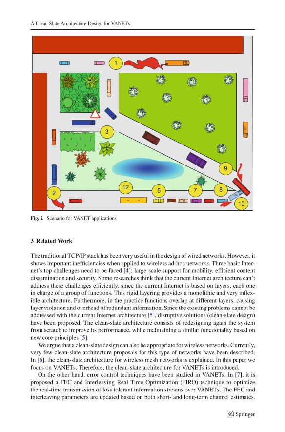
Some of the previously described applications (1, 2, 3, 5, 7, 8, 9, 10 and 12) are shown in Fig. 2.We observe that these applications take place simultaneously in the same geographical area.
123
A Clean Slate Architecture Design for VANETs
9
1
10
12 5 7 82
3
Fig. 2 Scenario for VANET applications
3 Related Work
The traditional TCP/IP stack has been very useful in the design of wired networks. However, itshows important inefficiencies when applied to wireless ad-hoc networks. Three basic Inter-net’s top challenges need to be faced [4]: large-scale support for mobility, efficient contentdissemination and security. Some researches think that the current Internet architecture can’taddress these challenges efficiently, since the current Internet is based on layers, each onein charge of a group of functions. This rigid layering provides a monolithic and very inflex-ible architecture. Furthermore, in the practice functions overlap at different layers, causinglayer violation and overhead of redundant information. Since the existing problems cannot beaddressed with the current Internet architecture [5], disruptive solutions (clean-slate design)have been proposed. The clean-slate architecture consists of redesigning again the systemfrom scratch to improve its performance, while maintaining a similar functionality based onnew core principles [5].
We argue that a clean-slate design can also be appropriate for wireless networks. Currently,very few clean-slate architecture proposals for this type of networks have been described.In [6], the clean-slate architecture for wireless mesh networks is explained. In this paper wefocus on VANETs. Therefore, the clean-slate architecture for VANETs is introduced.
On the other hand, error control techniques have been studied in VANETs. In [7], it isproposed a FEC and Interleaving Real Time Optimization (FIRO) technique to optimizethe real-time transmission of loss tolerant information streams over VANETs. The FEC andinterleaving parameters are updated based on both short- and long-term channel estimates.
123
M. C. Domingo, A. Reyes
The results show that this dynamic adaptation enhances communication quality consistently.However, in these works the effects of these error control schemes on the throughput effi-ciency have not been studied. In our paper, we analyse FEC block codes together with ARQschemes and compare them in terms of throughput efficiency for the proposed clean-slatearchitecture. Besides, different scenarios for VANETs have been considered.
4 Our Clean-Slate Architecture for VANETs
Many authors have suggested a cross-layer architecture for ad-hoc networks [8,9]. Althoughit performs better than the traditional TCP/IP stack, it also shows several drawbacks such asthe lack of interoperability between various types of network technologies and its complexity.
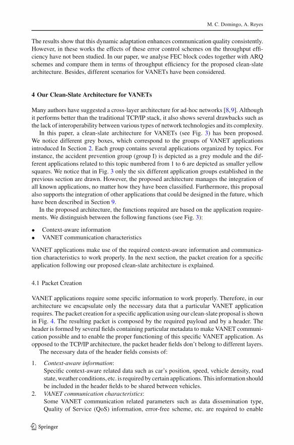
In this paper, a clean-slate architecture for VANETs (see Fig. 3) has been proposed.We notice different grey boxes, which correspond to the groups of VANET applicationsintroduced In Section 2. Each group contains several applications organized by topics. Forinstance, the accident prevention group (group I) is depicted as a grey module and the dif-ferent applications related to this topic numbered from 1 to 6 are depicted as smaller yellowsquares. We notice that in Fig. 3 only the six different application groups established in theprevious section are drawn. However, the proposed architecture manages the integration ofall known applications, no matter how they have been classified. Furthermore, this proposalalso supports the integration of other applications that could be designed in the future, whichhave been described in Section 9.
In the proposed architecture, the functions required are based on the application require-ments. We distinguish between the following functions (see Fig. 3):
• Context-aware information• VANET communication characteristics
VANET applications make use of the required context-aware information and communica-tion characteristics to work properly. In the next section, the packet creation for a specificapplication following our proposed clean-slate architecture is explained.
4.1 Packet Creation
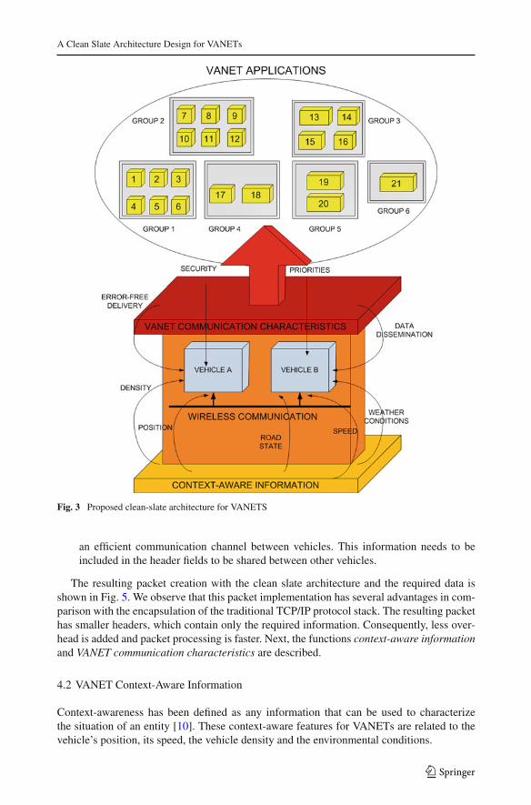
VANET applications require some specific information to work properly. Therefore, in ourarchitecture we encapsulate only the necessary data that a particular VANET applicationrequires. The packet creation for a specific application using our clean-slate proposal is shownin Fig. 4. The resulting packet is composed by the required payload and by a header. Theheader is formed by several fields containing particular metadata to make VANET communi-cation possible and to enable the proper functioning of this specific VANET application. Asopposed to the TCP/IP architecture, the packet header fields don’t belong to different layers.
The necessary data of the header fields consists of:
1. Context-aware information:Specific context-aware related data such as car’s position, speed, vehicle density, roadstate, weather conditions, etc. is required by certain applications. This information shouldbe included in the header fields to be shared between vehicles.
2. VANET communication characteristics:Some VANET communication related parameters such as data dissemination type,Quality of Service (QoS) information, error-free scheme, etc. are required to enable
123
A Clean Slate Architecture Design for VANETs
Fig. 3 Proposed clean-slate architecture for VANETS
an efficient communication channel between vehicles. This information needs to beincluded in the header fields to be shared between other vehicles.
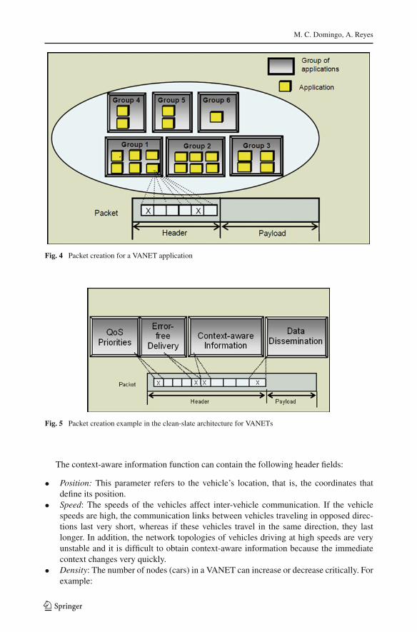
The resulting packet creation with the clean slate architecture and the required data isshown in Fig. 5. We observe that this packet implementation has several advantages in com-parison with the encapsulation of the traditional TCP/IP protocol stack. The resulting packethas smaller headers, which contain only the required information. Consequently, less over-head is added and packet processing is faster. Next, the functions context-aware informationand VANET communication characteristics are described.
4.2 VANET Context-Aware Information
Context-awareness has been defined as any information that can be used to characterizethe situation of an entity [10]. These context-aware features for VANETs are related to thevehicle’s position, its speed, the vehicle density and the environmental conditions.
123
M. C. Domingo, A. Reyes
Fig. 4 Packet creation for a VANET application
Fig. 5 Packet creation example in the clean-slate architecture for VANETs
The context-aware information function can contain the following header fields:
• Position: This parameter refers to the vehicle’s location, that is, the coordinates thatdefine its position.
• Speed: The speeds of the vehicles affect inter-vehicle communication. If the vehiclespeeds are high, the communication links between vehicles traveling in opposed direc-tions last very short, whereas if these vehicles travel in the same direction, they lastlonger. In addition, the network topologies of vehicles driving at high speeds are veryunstable and it is difficult to obtain context-aware information because the immediatecontext changes very quickly.
• Density: The number of nodes (cars) in a VANET can increase or decrease critically. Forexample:
123
A Clean Slate Architecture Design for VANETs
1. In case of accident, the node density increases rapidly.2. The highway density is very different than the density of urban areas or villages,
etc.
When many vehicles are driving or standing closely together, the node density is increased.A large number of messages are exchanged as vehicles change their position, state, etc. Con-sequently, high interference between different inter-vehicle communications and congestionproblems due to the low available bandwidth for communication arise.
If flooding techniques are applied in VANETs with a high vehicle density, channel con-gestion arises and packet collisions with contention-based mechanisms [11] are frequent.Applications should operate properly no matter if there are only a few vehicles on the street(low density) or if there is a traffic jam (high density). In any case, node density should beanalyzed to decide the best way to establish inter-vehicle communication.
• Weather conditions: This parameter is related to the local meteorological conditions(wind, rain, snow), which affect driving.
• Road state: This parameter refers to factors related to the local state of the road (wet roadsurface, presence of snow, etc.) which affect driving.
4.3 VANET Communication Characteristics
Certain necessary characteristics for VANET communication are introduced. They are relatedto the type of error control scheme, data dissemination mechanism, security protocol andquality of service model used for communication. In addition, our proposed architecturemaintains the link layer for practical issues.
The VANET communication function can contain the following header fields:
• QoS Priorities: The system must ensure a certain level of QoS to provide a goodcoverage to critical applications, which nowadays is difficult to achieve in any kindof wireless networks. This way, messages with high priority and hard real-time con-straints are delivered immediately; consequently, the allocated frequency bands willmost likely be reserved exclusively for safety applications [12]. Applications thatprovide comfort, information and entertainment to the passengers do not require sohigh priority levels. Thus, they may rely on different frequency bands than securityapplications.
• Data dissemination: Information dissemination in an efficient way is a fundamen-tal issue. Certain cooperative awareness applications require a continuous statusupdate via beacon messages [13]. Others need multihop dissemination of messagesin large areas for hazard notification, and others are based on detection/dissem-ination of congestion problems, which must be notified to warn drivers locatedseveral kilometers away to be able to use alternate routes. Therefore, we con-clude that information dissemination is adapted to the context and type of applica-tion.
• Error-free delivery: VANETs are highly dynamic and have harsh channel condi-tions due to the presence of multipath, noise and shadow fading. For this reason,robust error control schemes must be designed to achieve a reliable communica-tion.
• Security: Security is challenging in VANETs. The security solutions deployed for wirednetworks are not directly portable to ad hoc networks. Some ad hoc routing proto-cols are used for packet routing. However attacks related to the insertion of erroneous
123
M. C. Domingo, A. Reyes
routing information and the replay of old routing data are still open problems inVANETS.
In the next Section, the channel model for VANETs is described.
5 Channel Model
Next, we study the Line-of-sight (LOS) and the None-line-of-sight (NLOS) path loss mod-els. In LOS propagation, electromagnetic waves travel in a straight line, whereas in NLOSpropagation radio transmission across a path is partially obstructed.
The path loss model for a urban scenario can be expressed as follows [14]:
PLOS (d [m]) =
⎧⎪⎪⎪⎪⎨
⎪⎪⎪⎪⎩
22.7 log10 (d)+ 41 + 20 log10 ( fc [GHz] /5)if d < RBP
40 log10 (d)+ 41 − 17.3 log10 (RBP)
+20 log10 ( fc [GHz]/5)if d ≥ RBP
(1)
where RB P = (4 ·h′A ·h′
B · fc)/c, fc is the centre frequency, c = 3 ·108 m/s is the propagationvelocity in free space, h′
A and h′B are the effective antenna heights; they can be computed
as h′A = h A − h0, h′
B = h B–h0, where h A and h B are the actual antenna heights, and theeffective environment height in urban environments h0 is assumed to be 1.0 m (moderatetraffic conditions). We assume h A = h B = 1.5 m.
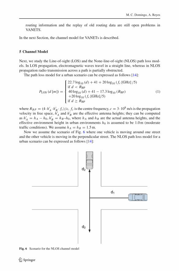
Now we assume the scenario of Fig. 6 where one vehicle is moving around one streetand the other vehicle is moving in the perpendicular street. The NLOS path loss model for aurban scenario can be expressed as follows [14]:
Fig. 6 Scenario for the NLOS channel model
123
A Clean Slate Architecture Design for VANETs
P LNLOS (d [m]) = PLOS (d1 [m])+ 20 − 12.5n j + 10n j log10 (d2 [m]) (2)
This equation is valid if 2 km > d2 > w/2, where w is the street width. d2 is the distanceapart from the middle point of the crossing of the vehicles. We assume d2 = 10 m. Theminimum allowed street width is w = 7 m; the proposed default value of w is w = 15 m.We assume that the propagation exponent n j is given by
n j = max(2.8 − 0.0024d1 ([m]) , 1.84) (3)
The received power at a distance d from the transmitter can be given by
PR (d) = PT − P L (d) (4)
where PT is the transmission power in dBm.Moreover, the Signal to Noise Ratio (SNR) at the receiver is given by
ψ(d) = PR(d)− Pn (5)
where Pn is the noise power in dBm.The expressions for Bit Error Rate (BER) and Packet Error Rate (PER) are derived. The
modulation scheme Binary Phase Shift Keying (BPSK) has been selected due to its BERimprovement. It is included as modulation scheme in the 802.11p PHY. Based on the biterror rate pb, the PER for each error control scheme can be calculated. The BER for BPSKis given by:
pBPSKb = 1
2erfc
(√Eb
N0
)
, Eb/N0 = ψBN
vT X(6)
For Automatic Repeat Request (ARQ), the Cyclic Redundancy Check (CRC) block codedetection mechanism is deployed. The PER of a single transmission for a packet of q bits is
PERCRC (q) = 1 − (1 − pb)q (7)
BCH (Bose, Ray-Chaudhuri, Hocquenghem) and RS (Reed-Solomon) FEC block codesare represented by (n, k, t), where n is the block length, k is the payload length, and t is theerror correcting capability in bits. For BCH and RS codes, the Block Error Rate (BLER) isgiven by
BLER (n, k, t) =n∑
i=t+1
(ni
)
pib (1 − pb)
n−i (8)
Since a packet can be larger than the block length n, the PER for BCH and RS block codesis given by
PERBC (q, n, k, t) = 1 − (1 − BLER (n, k, t))� q
k � (9)
where �q/k� is the number of blocks required to send q bits.
6 Packet Size Optimization
The throughput efficiency represents the useful fraction of the total throughput in a commu-nication link between sensors. It can be defined as:
λ = (1 − PER) ·(
s
s + h
)
(10)
123
M. C. Domingo, A. Reyes
where s refers to the payload length, h refers to the number of overhead bits and PER dependson the error control scheme.
We aim to maximize λwith respect to the payload length. It can be shown that there existsa maximum for the optimization function.
The optimal payload size for ARQ is given by
sARQopt
= −1
2h +
√
h2 − 4h
ln (1 − pb)(11)
The optimal payload length for FEC block codes is
sBCopt
= −1
2h +
√
h2 − 4hk
ln (1 − BLER)(12)
where k is the payload length of the FEC block code and BLER is given by (8).
7 Results
In this section, the performance of ARQ and FEC block codes with respect to the throughputefficiency for the proposed clean-slate architecture is analyzed.
A VANET that executes the Cooperative Collision Warning (CCW) application has beenstudied. A collision warning system is a safety application, which requires vehicles to knowthe motion of neighboring vehicles and the configuration of the neighboring roadway [15].The proposed application scenario consists of vehicles accelerating, decelerating, changinglanes, stopping and turning at speeds between 5 and 30 m/s [15]. In this application, context-aware information about vehicles (e.g. GPS position, speed or turn signal status) is sent toother neighboring vehicles over a wireless channel. The receiving vehicles use the incomingmessages to track the sending vehicle and detect potential collision threats. The driver is thenwarned if a threat exists. This application is able to detect collision threats, lane change/mergethreats and blind spot threats.
Next, we study the content of the CCW application packets.If the traditional layered architecture is used, UDP messages with a 160 byte payload
are sent between vehicles every 50 ms over IEEE 802.11b or IEEE 802.11p [15]. In [15],these messages are encapsulated with a minimum IP header of 20 bytes and a UDP headerof 8 bytes. Therefore, the UDP packet size has a size of 188 bytes. Every packet sent andreceived is logged with the corresponding timestamp and GPS position of the two vehicles.
We argue that several header fields of the UDP/IP stack are superfluous. For example, inthe IP header the field version is not required provided that all the vehicles in the VANETuse the same IP version. The differentiated services field is not useful if not used. The iden-tification, fragment offset and the three-bit flags fields are not required unless there is packetfragmentation. The header length field is not required if the field options is not included. Thefields total length, header checksum and protocol of the IP header and the fields length andchecksum of the UDP header are only necessary if the classical UDP/IP stack is used becausetheir information is only related to the IP protocol at the network layer or to the UDP protocolat the transport layer. On the contrary, our proposed clean-state architecture is non-layered.
Next, the required header fields for the CCW application packets using the proposedclean-slate architecture are described. It has been assumed that this application has certainrequirements such as dissemination of context-aware information around a certain geograph-ical area (for example TTL = 5 hops away).
123
A Clean Slate Architecture Design for VANETs
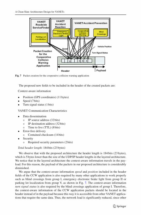
Fig. 7 Packet creation for the cooperative collision warning application
The proposed new fields to be included in the header of the created packets are:
Context-aware information
• Position (GPS coordinates) (11 bytes)• Speed (7 bits)• Turn signal status (1 bits)
VANET Communication Characteristics
• Data dissemination◦ IP source address (32 bits)◦ IP destination address (32 bits)◦ Time to live (TTL) (8 bits)
• Error-free delivery◦ Contained checksum (14 bits)
• Security◦ Required security parameters (2 bits)
Total header length: 184 bits (23 bytes)
We observe that with the proposed architecture the header length is 184 bits (23 bytes),which is 5 bytes lower than the size of the UDP/IP header lengths in the layered architecture.We notice that in the layered architecture the context-aware information travels in the pay-load. For this reason, the payload of the packets in our proposed architecture is considerablydiminished.
We argue that the context-aware information speed and position included in the headerfields of the CCW application is also required by many other applications to work properlysuch as blind crossings from group I, emergency electronic brake light from group II orparking lot localization from group V, as shown in Fig. 7. The context-aware informationturn signal status is also required by the blind crossings application of group I. Therefore,the context-aware information of the CCW application packets should be located in theheader instead of in the payload because this way it is accessible from other VANET applica-tions that require the same data. Thus, the network load is significantly reduced, since other
123
M. C. Domingo, A. Reyes
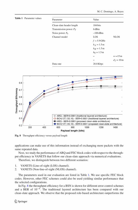
Table 1 Parameter values Parameter Value
Clean-slate header length 184 bits
Transmission power PT 6 dBm
Noise power Pn –100 dBm
Channel model LOS NLOS
f = 5.9 GHz
hA = 1.5 m
hB = 1.5 m
h0 = 1.5 m
– w=15 m
– d2 = 10 m
Data rate 28.8 Kbps
Fig. 8 Throughput efficiency versus payload length
applications can make use of this information instead of exchanging more packets with thesame repeated data.
Next, we study the performance of ARQ and FEC block codes with respect to the through-put efficiency in VANETS that follow our clean-slate approach via numerical evaluations.
Therefore, we distinguish between two different scenarios:
1. VANETS (Line-of-sight (LOS) channel).2. VANETS (Non-line-of-sight (NLOS) channel).
The parameters used in our evaluation are listed in Table 1. We use specific FEC blockcodes. However, other FEC schemes could also be used yielding similar performance thatthe selected configurations.
In Fig. 8 the throughput efficiency for a BSN is shown for different error control schemesand a BER of 10−4. The traditional layered architecture has been compared with ourclean-slate approach. We observe that the proposed role-based architecture outperforms the
123
A Clean Slate Architecture Design for VANETs
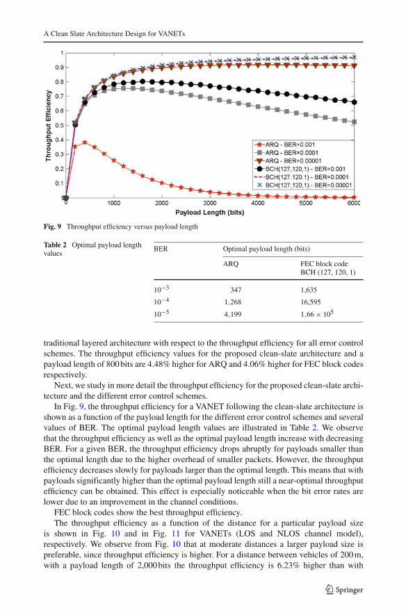
Fig. 9 Throughput efficiency versus payload length
Table 2 Optimal payload lengthvalues
BER Optimal payload length (bits)
ARQ FEC block codeBCH (127, 120, 1)
10−3 347 1,635
10−4 1,268 16,595
10−5 4,199 1,66 × 10⁵
traditional layered architecture with respect to the throughput efficiency for all error controlschemes. The throughput efficiency values for the proposed clean-slate architecture and apayload length of 800 bits are 4.48% higher for ARQ and 4.06% higher for FEC block codesrespectively.
Next, we study in more detail the throughput efficiency for the proposed clean-slate archi-tecture and the different error control schemes.
In Fig. 9, the throughput efficiency for a VANET following the clean-slate architecture isshown as a function of the payload length for the different error control schemes and severalvalues of BER. The optimal payload length values are illustrated in Table 2. We observethat the throughput efficiency as well as the optimal payload length increase with decreasingBER. For a given BER, the throughput efficiency drops abruptly for payloads smaller thanthe optimal length due to the higher overhead of smaller packets. However, the throughputefficiency decreases slowly for payloads larger than the optimal length. This means that withpayloads significantly higher than the optimal payload length still a near-optimal throughputefficiency can be obtained. This effect is especially noticeable when the bit error rates arelower due to an improvement in the channel conditions.
FEC block codes show the best throughput efficiency.The throughput efficiency as a function of the distance for a particular payload size
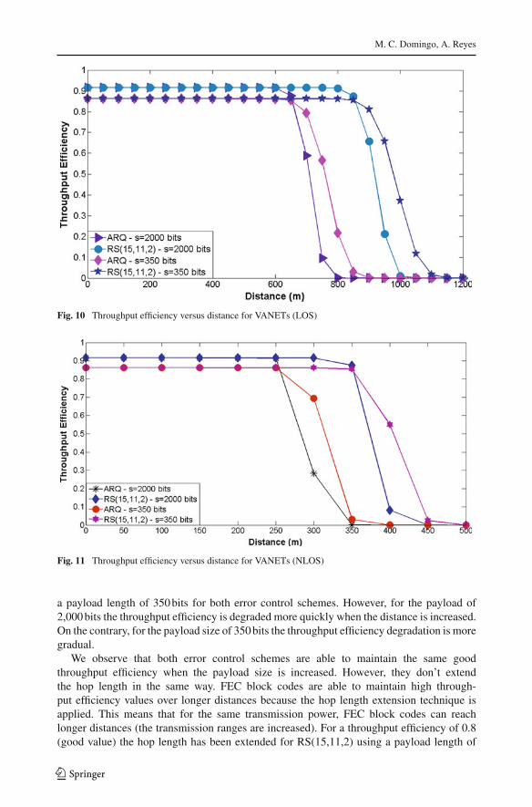
is shown in Fig. 10 and in Fig. 11 for VANETs (LOS and NLOS channel model),respectively. We observe from Fig. 10 that at moderate distances a larger payload size ispreferable, since throughput efficiency is higher. For a distance between vehicles of 200 m,with a payload length of 2,000 bits the throughput efficiency is 6.23% higher than with
123
M. C. Domingo, A. Reyes
Fig. 10 Throughput efficiency versus distance for VANETs (LOS)
Fig. 11 Throughput efficiency versus distance for VANETs (NLOS)
a payload length of 350 bits for both error control schemes. However, for the payload of2,000 bits the throughput efficiency is degraded more quickly when the distance is increased.On the contrary, for the payload size of 350 bits the throughput efficiency degradation is moregradual.
We observe that both error control schemes are able to maintain the same goodthroughput efficiency when the payload size is increased. However, they don’t extendthe hop length in the same way. FEC block codes are able to maintain high through-put efficiency values over longer distances because the hop length extension technique isapplied. This means that for the same transmission power, FEC block codes can reachlonger distances (the transmission ranges are increased). For a throughput efficiency of 0.8(good value) the hop length has been extended for RS(15,11,2) using a payload length of
123
A Clean Slate Architecture Design for VANETs
2,000 bits and BPSK modulation to 860 m for VANETs (LOS) and to 355 m for VANETs(NLOS).
8 Conclusions
This paper analyses the particular characteristics of VANET applications in order to design aspecific architecture that solves the current TCP/IP inefficiencies when applied to VANETs.The architecture is based on a clean-slate model that allows redesigning the system fromscratch, maintaining the link layer for practical issues but with new core principles thatimprove the VANETs performance.
The requirements of applications (such as dissemination of context-ware informationaround a certain geographical area) have been analyzed. The VANET communication char-acteristics have also been studied. The context-aware information as well as the VANETcommunication characteristics are designed to perform the required specific functions forapplications to work properly.
The context-aware information (speed, vehicle position, turn signal status) located in theheader fields of the CCW application packets is available by other different applications. Inaddition, unnecessary or redundant information of the traditional stack is eliminated. Thisway, the network load is significantly reduced.
The performance of ARQ and FEC codes with respect to the throughput efficiency inVANETs that follow our clean-slate approach has been analyzed. The optimal packet sizehas been determined for certain radio and channel parameters by maximizing the throughputefficiency. The numerical results show that the proposed role-based architecture outperformsthe traditional layered architecture with respect to the throughput efficiency for all errorcontrol schemes. FEC block codes show the best results. They are able to maintain highthroughput efficiency over longer distances because the hop length extension technique isapplied.
9 Future Work
We based our architecture design on what we can expect from future VANET applications ina generic way, for example most of the applications will be broadcast and proximity routingbased. There will be several VANETs cooperative scenarios, location aware content, etc.
Our proposed architecture uses current technologies but is based on clean-slate modelsthat allow an easy adaptation of our VANET architecture to support future VANET appli-cation scenarios. So, for future work we will analyze generic but also specific requirementsinvolved on future applications to adapt our VANET architecture. Some of the applicationswe think could be very interesting in a near future are:
9.1 Underwater Medium
Underwater VANETS will be developed as an evolution of nowadays existing AutonomousUnderwater Vehicles (AUVs) [16] and submarines. They will be able to cooperate togetherin many tasks and missions. Although these types of networks will make use of someVANET applications already introduced, new applications for underwater VANETS willalso be developed such as analysis of the seafloor for detailed map provision in the oil and
123
M. C. Domingo, A. Reyes
gas industry, detection of mines or monitoring of protected areas in military missions, pol-lution monitoring, detection of tsunamis and seaquakes, underwater transport of passengersacross the sea, etc.
9.2 Planet Discovery
VANET scenarios related to planet discovery such as the Mars exploration will be of vitalimportance in the future. VANETs will be designed to move through these planets andexchange information. They will be provided with vision systems to detect obstacles. Energyharvesting will be used as autonomous power source.
9.3 Unmanned VANETs
In this kind of networks, the vehicles are supposed to be unmanned and autonomous. Theidea is that the vehicles cooperate to achieve complex tasks. There are different scenarioswhere unmanned VANETs could be applied, for example: rescue after earthquakes, explora-tion of unknown environments, or cleaning of dangerous areas. Unmanned vehicles shouldnot be affected by energy constraints and they should be equipped with powerful processingunits, wireless transmitters, sensing devices such as GPS, chemical spill detectors, still/videocameras, vibration sensors, acoustic detectors, etc.
The coordination of unmanned vehicles for efficient cooperation requires disciplined waysto integrate, capture, maintain, validate, and extrapolate the environmental information.
Acknowledgments This work was supported by the Spanish Ministry of Education and Science under theprojects TIN2010-20140-C03-01 and TIN2010-20136-C03-01.
References
1. Car 2 Car Communication Consortium. http://www.car-to-car.org.2. Toor, Y., Muhlethaler, P., Laouiti, A., & de La Fortelle, A. (2008). Vehicle ad hoc networks: Applications
and related technical issues. IEEE Communications Surveys & Tutorials, 10(3), 74–88. Third Quarter.3. Qian, Y., & Moayeri, N. (2008). Design of secure and application-oriented VANETs. In Proceedings
of the IEEE Vehicular Technology Conference (VTC Spring 2008) (pp. 2794–2799). May 2008.4. Ortiz, S. (2008). Internet researchers look to wipe the slate clean. Computer, 41(1), 12–16.5. Feldmann, A. (2007). Internet clean-slate design: What and why?. SIGCOMM Computer Communication
Review, 37(3), 59–64.6. ElRakabawy, S. M., & Lindemann, C. (2009). A clean-slate architecture for reliable data delivery
in wireless mesh networks. In Proceedings of Wireless Communications and Networking Conference(WCNC 2009) (pp. 1–6). April (2009).
7. Bucciol, P., Zechinelli-Martini, J. L. & Vargas-Solar G. (2009). Optimized transmission of losstolerant information streams for real-time vehicle-to-vehicle communications. Mexican InternationalConference on Computer Science (ENC). Sept. 2009.
8. Sarma, N., & Nandi, S. (2006). QoS Support in Mobile Ad Hoc Networks. In Proceedings of theIFIP International Conference on Wireless and Optical Communications Networks (WOCN 2006).
9. Goldsmith, A. J., & Wicker, S. B. (2002). Design challenges for energy-constrained ad hoc wirelessnetworks. IEEE Wireless Communications, 9(4), 8–27.
10. Dey, A. K. (2001). Understanding and using context. Personal and Ubiquitous Computing. SpecialIssue on Situated Interaction and Ubiquitous Computing, 5(1), 4–7.
11. Bako, B., Kargl, F., Schoch, E. & Weber, M. (2008). Evaluation of position based gossiping forVANETs in an intersection scenario. In Proceedings of the Fourth International Conference onNetworked Computing and Advanced Information Management (NCM ’08) (Vol. 1, pp. 397–402).Sept. 2008.
123
A Clean Slate Architecture Design for VANETs
12. Baldessari, R., Festag, A., & Abeille, J. (2007). NEMO meets VANET: A deployability analysis ofnetwork mobility in vehicular communication. In Proceedings of 7th International Conference onTelecommunications (ITST ’07) (pp. 1–6). June 2007
13. Dietzel, S., Schoch, E., Bako, B., & Kargl, F. (2009). A structure-free aggregation framework for vehic-ular ad hoc networks. In Proceedings of the 6th International Workshop on Intelligent Transportation(WIT 2009). Germany: Hamburg.
14. Wireless World Initiative New Radio (WINNER) Information Society Technology, D1.1.1.WINNERII interim channel models. http://www.ist-winner.org/deliverables.html.
15. Sengupta, R., Rezaei, S., Shladover, S. E., Misener, J. A., Dickey, S., & Krishnan, H. (2007). Coop-erative collision warning systems: Concept definition and experimental implementation. Journal ofIntelligent Transportation Systems, 11(3), 143–155.
16. Bellingham, J. G., Goudey, C. A., Consi, T. R., Bales, J. W., Atwood, D. K., Leonard J. J. et al., (1994).A second generation survey AUV. In Proceedings of the Symposium on Autonomous UnderwaterVehicle Technology (AUV ’94). July 1994.
Author Biographies
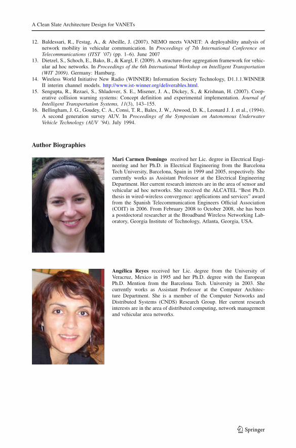
Mari Carmen Domingo received her Lic. degree in Electrical Engi-neering and her Ph.D. in Electrical Engineering from the BarcelonaTech University, Barcelona, Spain in 1999 and 2005, respectively. Shecurrently works as Assistant Professor at the Electrical EngineeringDepartment. Her current research interests are in the area of sensor andvehicular ad hoc networks. She received the ALCATEL “Best Ph.D.thesis in wired-wireless convergence: applications and services” awardfrom the Spanish Telecommunication Engineers Official Association(COIT) in 2006. From February 2008 to October 2008, she has beena postdoctoral researcher at the Broadband Wireless Networking Lab-oratory, Georgia Institute of Technology, Atlanta, Georgia, USA.
Angélica Reyes received her Lic. degree from the University ofVeracruz, Mexico in 1995 and her Ph.D. degree with the EuropeanPh.D. Mention from the Barcelona Tech. University in 2003. Shecurrently works as Assistant Professor at the Computer Architec-ture Department. She is a member of the Computer Networks andDistributed Systems (CNDS) Research Group. Her current researchinterests are in the area of distributed computing, network managementand vehicular area networks.
123
Related Documents