Design and Construction of Stadium Tiers – A Case Study of R. Premadasa Stadium, Sri Lanka D.T.Rajasekaran, B.Sc. Eng. (Peradeniya), P.G. Dip. (Structural, Moratuwa), C.Eng, MIE(Sri Lanka), MSSE(SL), Senior Structural Engineer, State Engineering Corporation, Sri Lanka Email: [email protected] H.D.D.Lakmali Jayaweera, B.Sc Eng. (Moratuwa), M. Eng. Student (Structural, Moratuwa), AMIE (Sri Lanka), AMSSE(SL), Structural Engineer, State Engineering Corporation, Sri Lanka Email: [email protected] Abstract The R.Premadasa International Stadium which is one of the largest stadiums in the country and the only ground in Colombo with flood lights was one of the venues for the tenth ICC Cricket World Cup 2011. The ground which had 15,000 seating capacity was refurbished and reconstructed to increase the seating capacity to 35,000. Under this massive construction project almost buildings around the ground was added with structures to increase the seating capacity and also the existing roof was replaced with a new steel roof. Even the project was very large the time duration given for the design and the completion of construction was only one year. Since the main aim was to increase the seating capacity priority was given to design and construction of stadium tiers and the supporting arrangement. There were many shortcomings with the existed stadium tiers as they were the pre-stressed double “T” sections. Speed of construction and cost effectiveness could not be achieved with them. Precise formwork system and limited area of casting beds were the main problems encountered with casting. Also there was a major problem of water leaking through the brickwork at the edge of the tier connection. In order to overcome the above problems, a new system was identified, analyzed, designed and constructed. Compared with in-situ tiers the new pre-cast system had great advantages in both time and cost. The shape was modified and the weight per unit was limited to overcome the above problems and for the ease of handling. The paper will discuss the types of stadium tiers, design and construction aspects and both advantages and disadvantages. With all these efforts the hosting of World Cup Cricket Matches in R. Premadasa Stadium became a reality. Key words: Stadium Tiers, Pre-stressed Tiers, Pre-cast Tiers, Stringer Beams, Load Test

Welcome message from author
This document is posted to help you gain knowledge. Please leave a comment to let me know what you think about it! Share it to your friends and learn new things together.
Transcript
Design and Construction of Stadium Tiers – A Case Study of R. Premadasa Stadium, Sri Lanka
D.T.Rajasekaran,
B.Sc. Eng. (Peradeniya), P.G. Dip. (Structural, Moratuwa), C.Eng, MIE(Sri Lanka), MSSE(SL),
Senior Structural Engineer, State Engineering Corporation, Sri Lanka
Email: [email protected]
H.D.D.Lakmali Jayaweera,
B.Sc Eng. (Moratuwa), M. Eng. Student (Structural, Moratuwa), AMIE (Sri Lanka),
AMSSE(SL), Structural Engineer, State Engineering Corporation, Sri Lanka
Email: [email protected]
Abstract
The R.Premadasa International Stadium which is one of the largest stadiums in the
country and the only ground in Colombo with flood lights was one of the venues for the
tenth ICC Cricket World Cup 2011. The ground which had 15,000 seating capacity was
refurbished and reconstructed to increase the seating capacity to 35,000. Under this
massive construction project almost buildings around the ground was added with
structures to increase the seating capacity and also the existing roof was replaced with a
new steel roof. Even the project was very large the time duration given for the design and
the completion of construction was only one year. Since the main aim was to increase the
seating capacity priority was given to design and construction of stadium tiers and the
supporting arrangement. There were many shortcomings with the existed stadium tiers as
they were the pre-stressed double “T” sections. Speed of construction and cost
effectiveness could not be achieved with them. Precise formwork system and limited area
of casting beds were the main problems encountered with casting. Also there was a major
problem of water leaking through the brickwork at the edge of the tier connection. In
order to overcome the above problems, a new system was identified, analyzed, designed
and constructed. Compared with in-situ tiers the new pre-cast system had great
advantages in both time and cost. The shape was modified and the weight per unit was
limited to overcome the above problems and for the ease of handling.
The paper will discuss the types of stadium tiers, design and construction aspects and
both advantages and disadvantages. With all these efforts the hosting of World Cup
Cricket Matches in R. Premadasa Stadium became a reality.
Key words: Stadium Tiers, Pre-stressed Tiers, Pre-cast Tiers, Stringer Beams, Load Test
1. Introduction
Cricket is a game with a lot of uncertainties. Sri Lanka hosted twelve 2011 ICC world cup
matches, the Premadasa Stadium hosting seven, including the first semi-final, New Zealand vs
Sri Lanka. Hambanthota and Pallekele hosted two and three games respectively [1]. The crowd
was impossible to control on 29th March 2011which was at the first semi-final, New Zealand vs
Sri Lanka. The tickets were sold at double its original price. It was no doubt that an immense
support was given to our cricket team by our spectators at Keththarama.
The R. Premadasa international Stadium (Known prior to June 1994 as the Keththarama Cricket
Stadium, after the area of Colombo it stands in) was the brainchild of the late Sri Lanka’s late
president Ranasinghe Premadasa, who championed the development of this colossal 35,000 –
seater concrete bowl, the biggest stadium in the country. [2]
The first semi-final of 2011 Cricket World Cup Tournament was one of the real cases which
exceeded the expected capacity and it was one of the guarantees that its capacity is more than
the designed.
It was a case that the stadium tiers reached near to its ultimate capacity without minor damage.
As mentioned before previous capacity of 15,000 was increased to 35,000. The challenge was
to increase the seating capacity by 233%. As it was the main objective of the project, many
discussions went on about the seating capacity. The basic limiting factor was the time.
Everything was to be designed and constructed within a very short period of 10 months.
The land area of the ground was unchangeable; the only possibility was to increase the number
of storeys and floor area. Both possibilities were executed to increase the seating capacity. From
here onwards the paper discusses the stadium tiers, design and construction aspects and both
advantages and disadvantages of the selected systems.
2. Stadium Tiers
Pre-stressed double “T” sections have been used in earlier 15,000 seater concrete bowl. There
were another two options for stadium tiers. The first option was an asymmetrical pre-stressed
section with six pre stressed wires. The second option was the best among all, pre-cast with
normal reinforcement. All together there were three options to produce concrete tiers for
Keththarama Stadium.
2.1 Pre-Stressed Double “T” Section
As in all the pre-stressed members pre-stressed double “T” section is where a pre-stress force is
applied at the bottom of the webs (Fig. 1), counteracts all or part of the tensile stresses set up in
the member by applied loading. Therefore under service condition the section performed well
with no deflection at all.
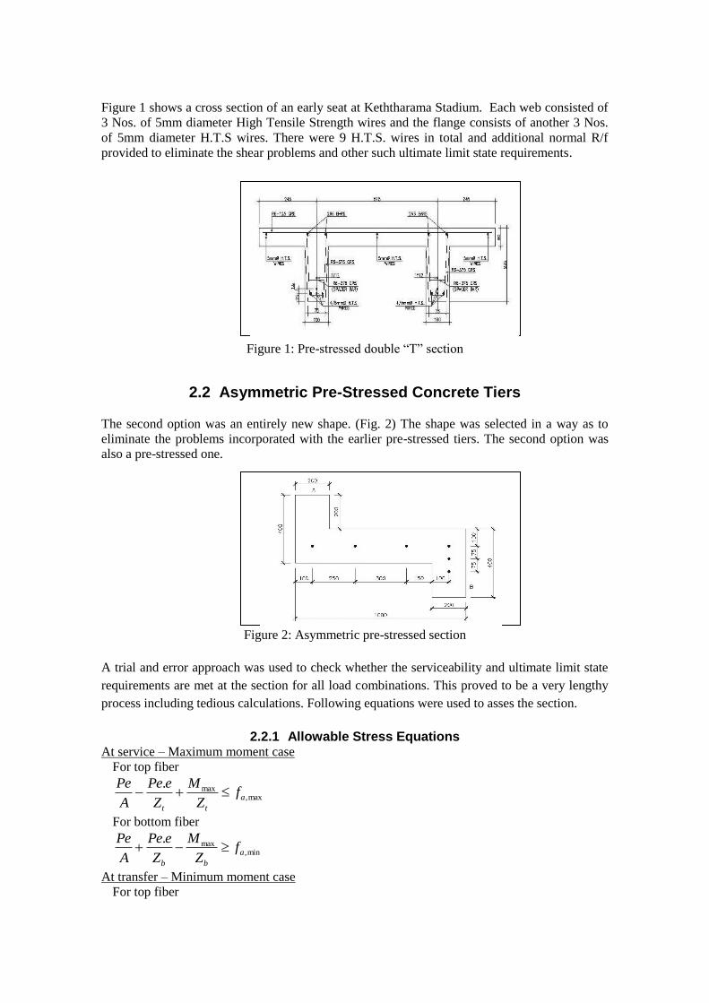
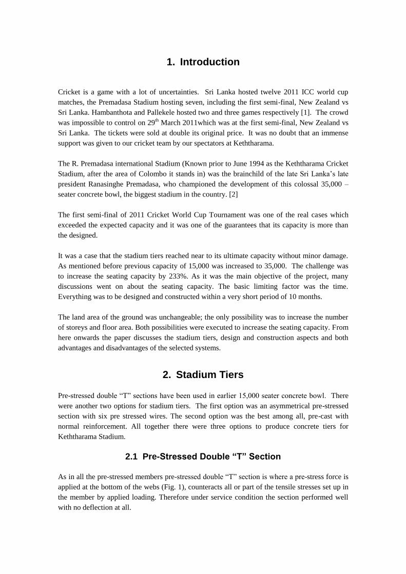
Figure 1 shows a cross section of an early seat at Keththarama Stadium. Each web consisted of
3 Nos. of 5mm diameter High Tensile Strength wires and the flange consists of another 3 Nos.
of 5mm diameter H.T.S wires. There were 9 H.T.S. wires in total and additional normal R/f
provided to eliminate the shear problems and other such ultimate limit state requirements.
Figure 1: Pre-stressed double “T” section
2.2 Asymmetric Pre-Stressed Concrete Tiers
The second option was an entirely new shape. (Fig. 2) The shape was selected in a way as to
eliminate the problems incorporated with the earlier pre-stressed tiers. The second option was
also a pre-stressed one.
Figure 2: Asymmetric pre-stressed section
A trial and error approach was used to check whether the serviceability and ultimate limit state
requirements are met at the section for all load combinations. This proved to be a very lengthy
process including tedious calculations. Following equations were used to asses the section.
2.2.1 Allowable Stress Equations At service – Maximum moment case
For top fiber
max,max.
a
tt
fZ
M
Z
ePe
A
Pe
For bottom fiber
min,max.
a
bb
fZ
M
Z
ePe
A
Pe
At transfer – Minimum moment case
For top fiber
ta
t
o
t
fZ
M
Z
ePi
A
Pimin,
.
For bottom fiber
ta
b
o
b
fZ
M
Z
ePi
A
Pimax,
.
Pe - Applied pre-stressed force
Pi - Initial pre-stressed force
A - Area of the section
e - Eccentricity
bt ZZ , - Elastic section modulie for top and bottom fiber
oMM ,max - Maximum and minimum moments
min,max, , aa ff - Allowable compressive stresses in concrete
tata ff min,max, , - Allowable compressive stresses in concrete at transfer
The second option also was rejected because of the heavy weight of the member (Table 1).
Material requirement was higher than all possible options. Not only that but also all the
problems related with pre-stressed members could definitely be related with it. Therefore
priority was given to the third option.
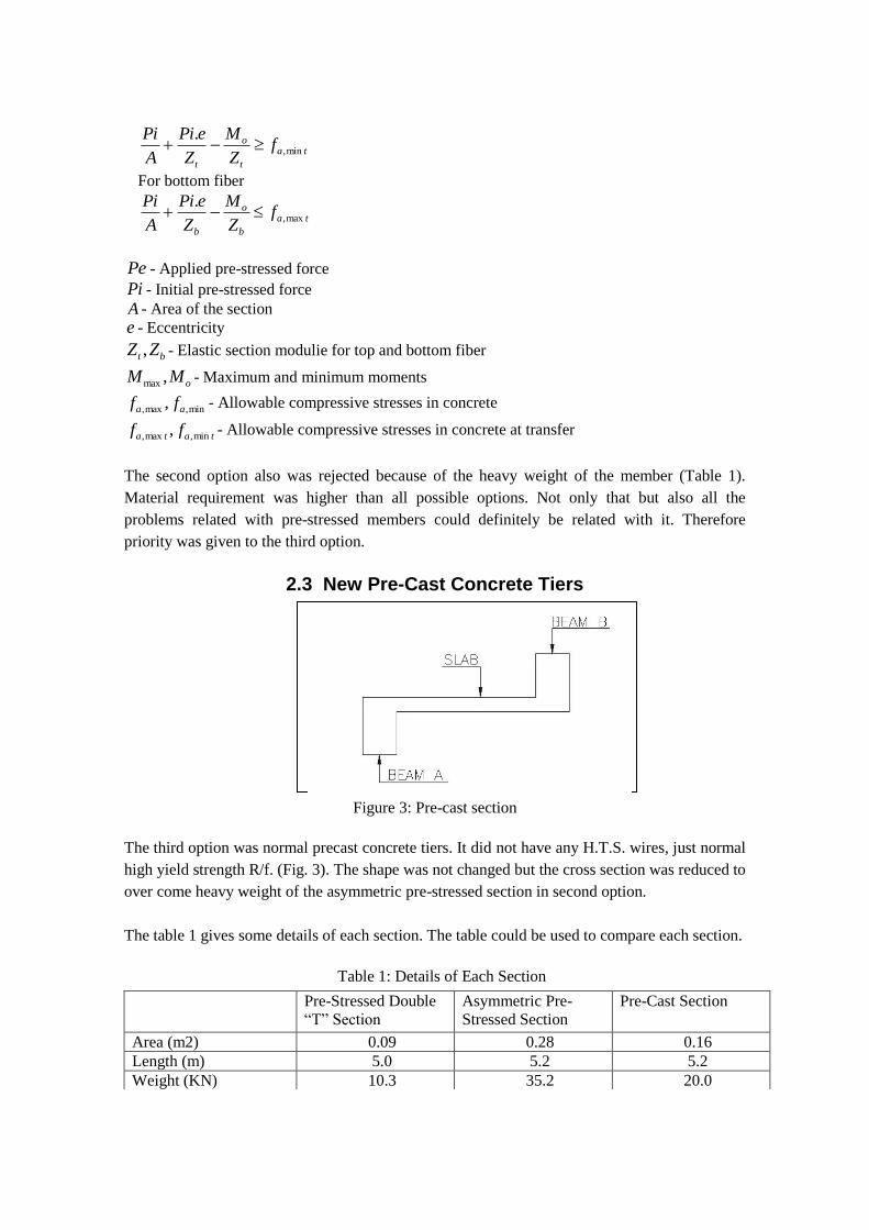
2.3 New Pre-Cast Concrete Tiers
Figure 3: Pre-cast section
The third option was normal precast concrete tiers. It did not have any H.T.S. wires, just normal
high yield strength R/f. (Fig. 3). The shape was not changed but the cross section was reduced to
over come heavy weight of the asymmetric pre-stressed section in second option.
The table 1 gives some details of each section. The table could be used to compare each section.
Table 1: Details of Each Section
Pre-Stressed Double
“T” Section Asymmetric Pre-
Stressed Section Pre-Cast Section
Area (m2) 0.09 0.28 0.16 Length (m) 5.0 5.2 5.2 Weight (KN) 10.3 35.2 20.0
3. Advantages and Disadvantages
As in all pre-stressed members the main advantage of the early system was, for a given span and
loading a smaller pre-stressed concrete member was required. This saving of the dead load of
the structure may be particularly important in long span structures. Such as bridges [3]. In the
case of Keththarama ground, the grids were radial and at the far end it was about 6.5 m and at
the internal edge (near the ground) it was about 6.15m. Therefore much benefit could not be
obtained. For the ease of casting the spans of the tiers were limited to a maximum span of 5.2m.
Since the span was considerably small there was no significant weight reduction.
Therefore the interrelated advantages such as reduction in concrete for members, saving in
foundation cost were not a significant factor in foundation construction. Since the number of
HTS wires were high in early system there was no considerable saving on cost as well. The cost
per member increased drastically with the pre-stressing force and jacking force.
But on the other hand it produced a crack free section which had important implications for
durability only on the top of the seating. Also the earlier system had eliminated the deflection
entirely. The reason was the eccentric pre-stress force of a member would cause a vertical
deflection, usually in the opposite direction to that cause by the applied lading [3].
Against the advantages listed above, there were some disadvantages of the old system. The fact
that the concrete members under any loading condition may give rise to inherent problems due
to long term creep movement. There may be a big reduction in applied pre-stressing force with
that. Therefore a high level of quality control is required, both for material production and for
locating the tendons within the member [3].
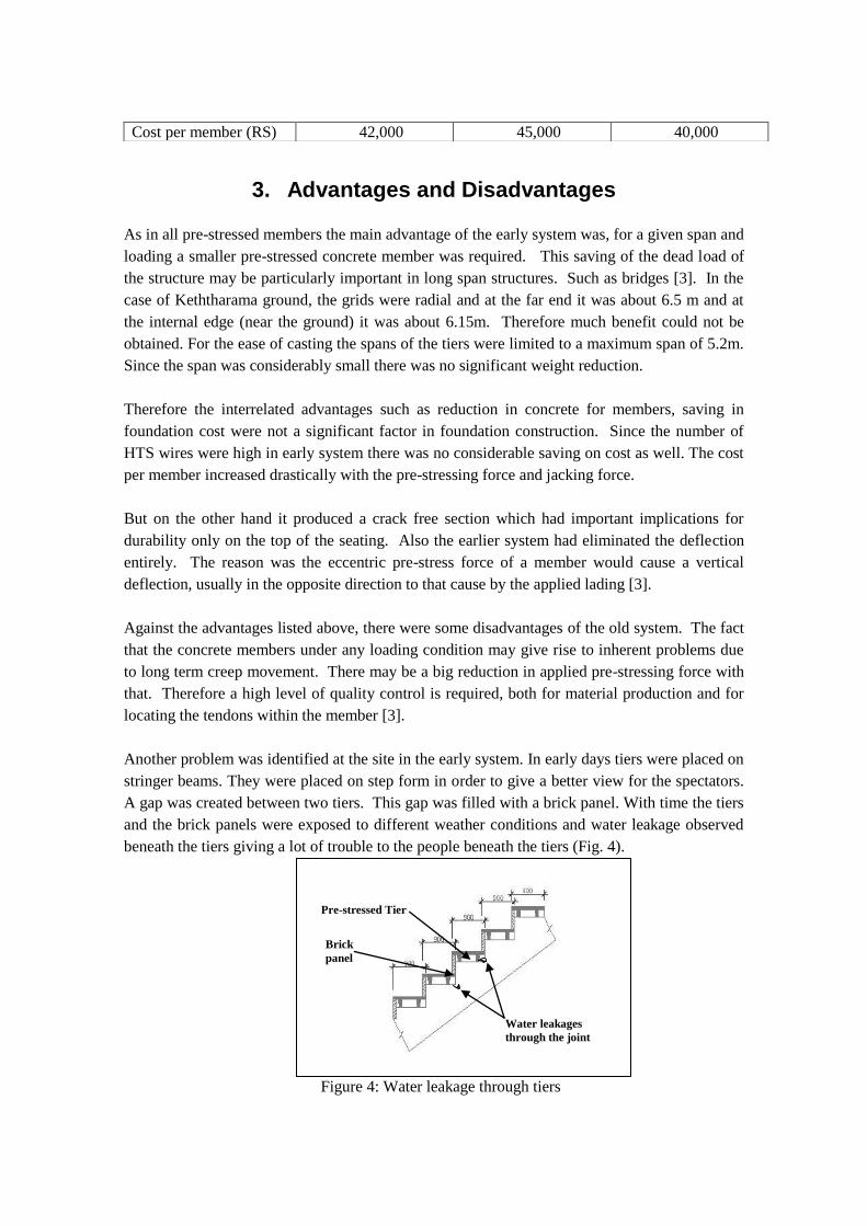
Another problem was identified at the site in the early system. In early days tiers were placed on
stringer beams. They were placed on step form in order to give a better view for the spectators.
A gap was created between two tiers. This gap was filled with a brick panel. With time the tiers
and the brick panels were exposed to different weather conditions and water leakage observed
beneath the tiers giving a lot of trouble to the people beneath the tiers (Fig. 4).
Figure 4: Water leakage through tiers
Cost per member (RS) 42,000 45,000 40,000
Water leakages
through the joint
Brick
panel
Pre-stressed Tier
The reason for the water leakage was uneven shrinkage between pre-stressed concrete tiers and
the mortar joint of the brick panel. Therefore a lot of precautions were taken to over come
above problem. The waterproofing materials were applied. Also it was not the only problem.
The slab was very thin and the number of tendons was high. Therefore high quality control
measures to be taken at yard to eliminate the problems of excessive deflections at the time of
cutting the tendons.
A large number of casting beds was required to produce the huge quantity. Time was a big
challenge for the project and early system was dropped due to its short comings.
The second option, an entirely new section involved all sort of considerations. Once they were
placed on stringer beams there would not be any water leakage problems. Determination of the
stress distribution was done using the general form of the expression for elastic stresses for
asymmetrical sections (Section 2.2.1). From calculations it was found that the section selected
was just at the boundaries of the limiting stress conditions at service and transfer. But no further
calculations were done since the weight of the section was more than required (Table 1). Also
the number of H.T.S. wires was six and more R/f was requireded to eliminate shear problems
and ultimate limit state cracks.
As mentioned previously all cases of practical problems of pre-stressing were associated with it.
The problems such as number of casting beds and the unit weight per member were the
problems as earlier. Therefore third option was executed.
The third option was simple and more suitable. It could avoid many problems. It did not require
skilled labour and really it was cost effective. With third option weight per one unit was limited
and could avoid the problem of casting beds. As it was not pre-stressed there was no waiting
time for concrete strength gain. The design method was simple as beam, slab design. It was
just slab loading transferred to a simply supported beams up stand and down stand.
But it gave a lot of advantages than the previous. It did not require special waterproofing at all.
Normal brush applied waterproofing was required just to protect the section from heavily
showers. Therefore the third option was analyzed in detail and executed at the site. From here
onwards the paper presents the design and construction method of new pre-cast system which
was the third option.
4. Pre-Cast tiers
This section comes under different headings of Pre-cast tiers. The design, construction and even
the testing also are given under relevant headings.
4.1 Design of Pre-Cast Tiers
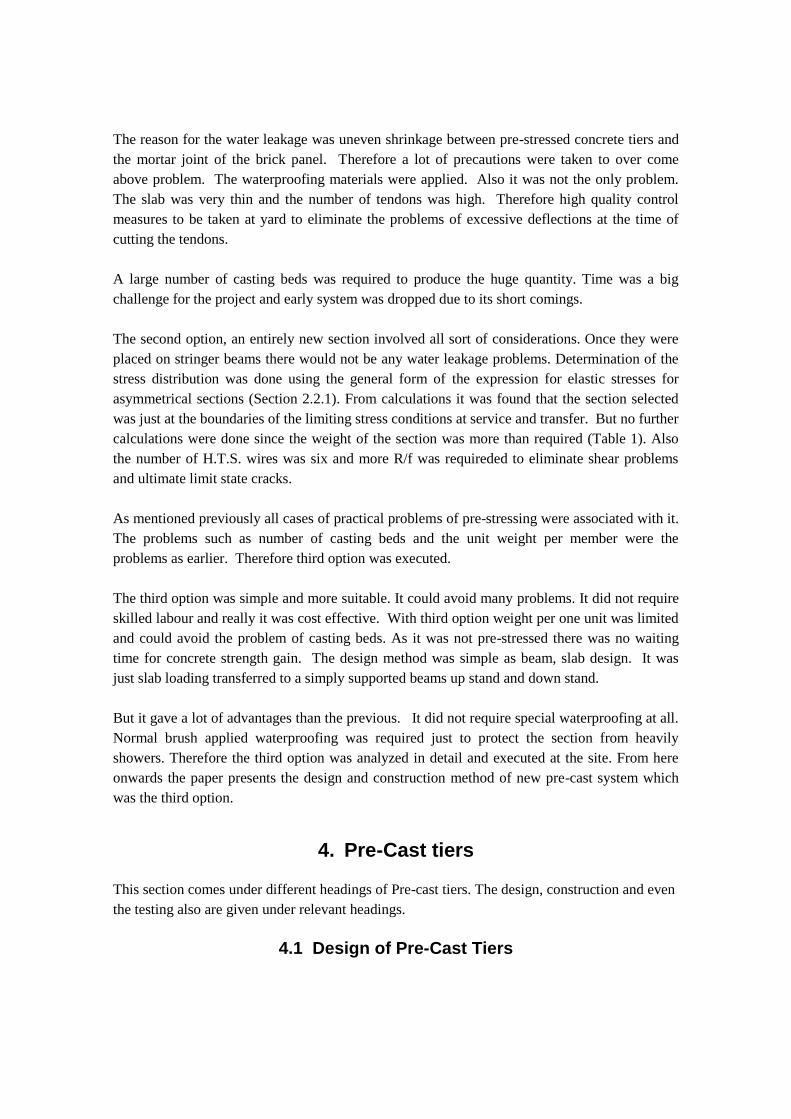
Since the problem was identified properly the shape selected for the second option was adopted
for the new tiers. The design was as normal RC member according to BS 8110 Part1 (Fig. 3).
Thickness of the slab at the middle slab was kept to 75mm. The slab spanned between the two
beams A and B. The cover for the R/f in the middle was kept as 20mm. It gave adequate
durability to the member as it was not fully exposed to the environment and the grade of the
concrete was 30N/mm2. The slab R/f was T10 @ 200 crs.
Figure 5: Detailed sketch of a pre-cast tier
The beams A and B (Fig. 3) were designed as simply supported span of 5.2 m. The loading was
self weight and the service live load of spectators. The “L” beam action was ignored in the
design for more conservative design. (Obviously there was no any “L” beam action for beam B;
it was only for beam A.) The detailed pre cast tier is shown in Figure 5.
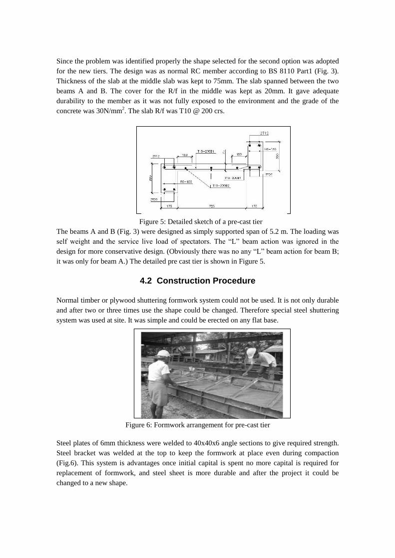
4.2 Construction Procedure
Normal timber or plywood shuttering formwork system could not be used. It is not only durable
and after two or three times use the shape could be changed. Therefore special steel shuttering
system was used at site. It was simple and could be erected on any flat base.
Figure 6: Formwork arrangement for pre-cast tier
Steel plates of 6mm thickness were welded to 40x40x6 angle sections to give required strength.
Steel bracket was welded at the top to keep the formwork at place even during compaction
(Fig.6). This system is advantages once initial capital is spent no more capital is required for
replacement of formwork, and steel sheet is more durable and after the project it could be
changed to a new shape.
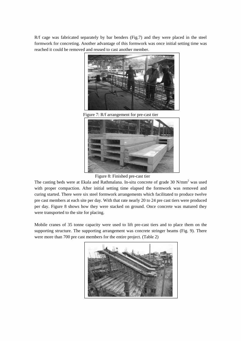
R/f cage was fabricated separately by bar benders (Fig.7) and they were placed in the steel
formwork for concreting. Another advantage of this formwork was once initial setting time was
reached it could be removed and reused to cast another member.
Figure 7: R/f arrangement for pre-cast tier
Figure 8: Finished pre-cast tier
The casting beds were at Ekala and Rathmalana. In-situ concrete of grade 30 N/mm2 was used
with proper compaction. After initial setting time elapsed the formwork was removed and
curing started. There were six steel formwork arrangements which facilitated to produce twelve
pre cast members at each site per day. With that rate nearly 20 to 24 pre cast tiers were produced
per day. Figure 8 shows how they were stacked on ground. Once concrete was matured they
were transported to the site for placing.
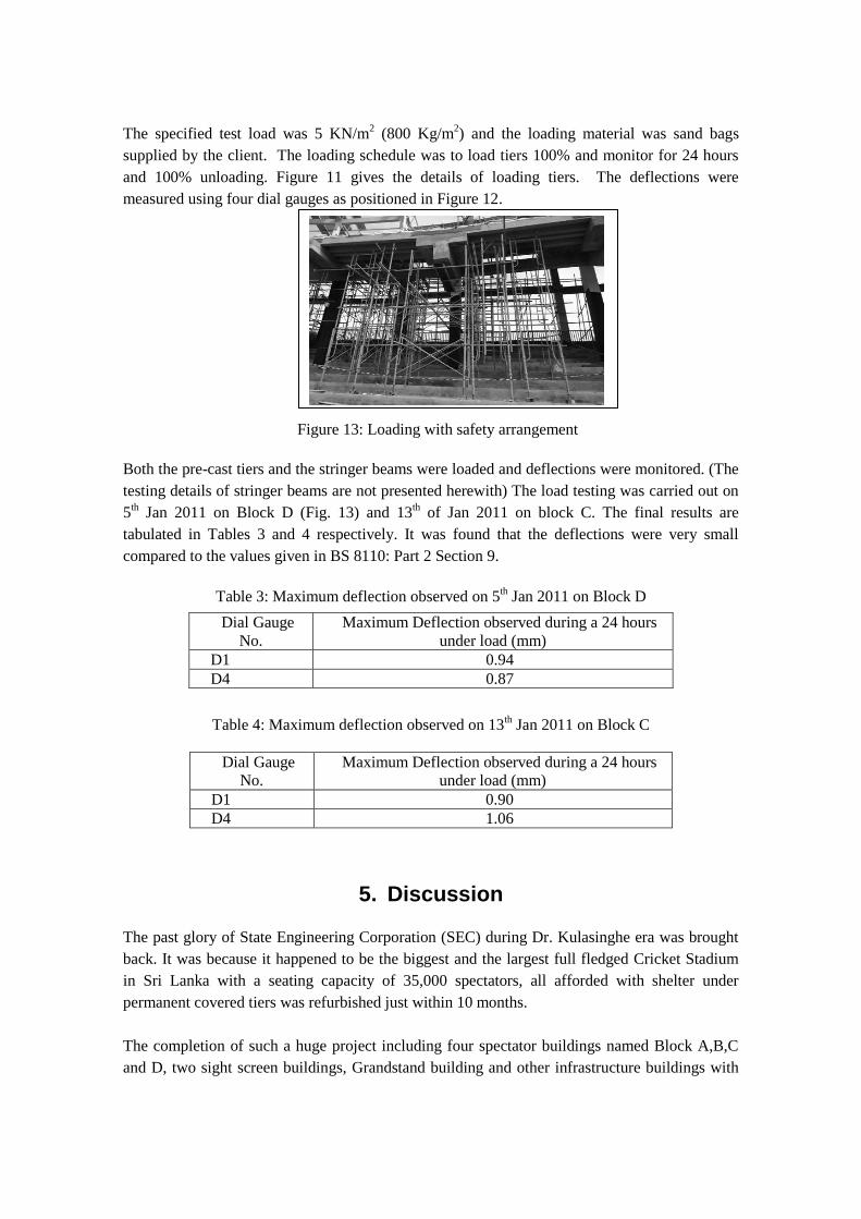
Mobile cranes of 35 tonne capacity were used to lift pre-cast tiers and to place them on the
supporting structure. The supporting arrangement was concrete stringer beams (Fig. 9). There
were more than 700 pre cast members for the entire project. (Table 2)
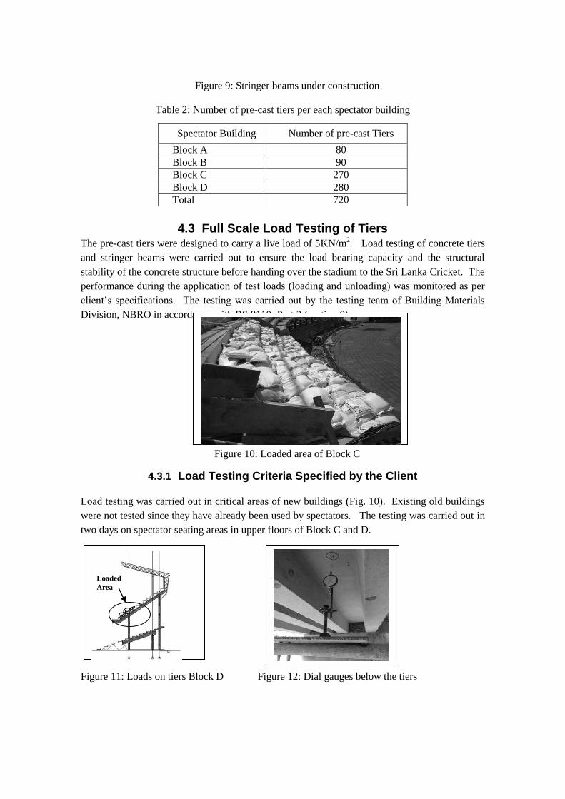
Figure 9: Stringer beams under construction
Table 2: Number of pre-cast tiers per each spectator building
4.3 Full Scale Load Testing of Tiers The pre-cast tiers were designed to carry a live load of 5KN/m
2. Load testing of concrete tiers
and stringer beams were carried out to ensure the load bearing capacity and the structural
stability of the concrete structure before handing over the stadium to the Sri Lanka Cricket. The
performance during the application of test loads (loading and unloading) was monitored as per
client’s specifications. The testing was carried out by the testing team of Building Materials
Division, NBRO in accordance with BS 8110: Part 2 (section 9).
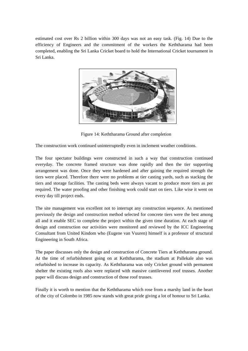
Figure 10: Loaded area of Block C
4.3.1 Load Testing Criteria Specified by the Client
Load testing was carried out in critical areas of new buildings (Fig. 10). Existing old buildings
were not tested since they have already been used by spectators. The testing was carried out in
two days on spectator seating areas in upper floors of Block C and D.
Figure 11: Loads on tiers Block D Figure 12: Dial gauges below the tiers
Spectator Building Number of pre-cast Tiers
Block A 80 Block B 90 Block C 270 Block D 280 Total 720
Loaded
Area
The specified test load was 5 KN/m2 (800 Kg/m
2) and the loading material was sand bags
supplied by the client. The loading schedule was to load tiers 100% and monitor for 24 hours
and 100% unloading. Figure 11 gives the details of loading tiers. The deflections were
measured using four dial gauges as positioned in Figure 12.
Figure 13: Loading with safety arrangement
Both the pre-cast tiers and the stringer beams were loaded and deflections were monitored. (The
testing details of stringer beams are not presented herewith) The load testing was carried out on
5th Jan 2011 on Block D (Fig. 13) and 13
th of Jan 2011 on block C. The final results are
tabulated in Tables 3 and 4 respectively. It was found that the deflections were very small
compared to the values given in BS 8110: Part 2 Section 9.
Table 3: Maximum deflection observed on 5th Jan 2011 on Block D
Table 4: Maximum deflection observed on 13th Jan 2011 on Block C
Dial Gauge
No. Maximum Deflection observed during a 24 hours
under load (mm) D1 0.90 D4 1.06
5. Discussion
The past glory of State Engineering Corporation (SEC) during Dr. Kulasinghe era was brought
back. It was because it happened to be the biggest and the largest full fledged Cricket Stadium
in Sri Lanka with a seating capacity of 35,000 spectators, all afforded with shelter under
permanent covered tiers was refurbished just within 10 months.
The completion of such a huge project including four spectator buildings named Block A,B,C
and D, two sight screen buildings, Grandstand building and other infrastructure buildings with
Dial Gauge
No. Maximum Deflection observed during a 24 hours
under load (mm) D1 0.94 D4 0.87
estimated cost over Rs 2 billion within 300 days was not an easy task. (Fig. 14) Due to the
efficiency of Engineers and the commitment of the workers the Keththarama had been
completed, enabling the Sri Lanka Cricket board to hold the International Cricket tournament in
Sri Lanka.
Figure 14: Keththarama Ground after completion
The construction work continued uninterruptedly even in inclement weather conditions.
The four spectator buildings were constructed in such a way that construction continued
everyday. The concrete framed structure was done rapidly and then the tier supporting
arrangement was done. Once they were hardened and after gaining the required strength the
tiers were placed. Therefore there were no problems at tier casting yards, such as stacking the
tiers and storage facilities. The casting beds were always vacant to produce more tiers as per
required. The water proofing and other finishing work could start on tiers. Like wise it went on
every day till project ends.
The site management was excellent not to interrupt any construction sequence. As mentioned
previously the design and construction method selected for concrete tiers were the best among
all and it enable SEC to complete the project within the given time duration. At each stage of
design and construction our activities were monitored and reviewed by the ICC Engineering
Consultant from United Kindom who (Eugene van Vuuren) himself is a professor of structural
Engineering in South Africa.
The paper discusses only the design and construction of Concrete Tiers at Keththarama ground.
At the time of refurbishment going on at Keththarama, the stadium at Pallekale also was
refurbished to increase its capacity. As Keththarama was only Cricket ground with permanent
shelter the existing roofs also were replaced with massive cantilevered roof trusses. Another
paper will discuss design and construction of those roof trusses.
Finally it is worth to mention that the Keththarama which rose from a marshy land in the heart
of the city of Colombo in 1985 now stands with great pride giving a lot of honour to Sri Lanka.
6. Conclusion
From this case study it can be concluded that previous tier system the best in reducing the
dead weight of the structure. But it would not be advantageous with constrains on time and
casting beds. Even though the second system eliminated the problems such as water leakages
but involves tedious calculations which consumes a lot of time. As in the case of previous tiers,
the disadvantages of pre-stressed members were interconnected with it.
The third option, normal R/f concrete pre-cast tiers which was executed on the site was the
best among all gave a lot of flexibility in design and construction. Therefore the third option
would be a better option for construction of stadium tiers for spectators when time of
construction is a constraint.
7. Acknowledgement
The authors wish to convey their heartiest gratitude to entire Designs staff including the Chief
Eng. Designs M. D. Pathmasiri and Eng. A. A. Piyadasa DGM (Construction Components) of
State Engineering Corporation. Also they acknowledge all SEC staff including Engineers,
Architects, Quantity surveyors, Draftsmen and the other minor staff whose names are not
mentioned to make this huge project a success. It is mentioned with pleasure that from the
beginning to end of the project it was entirely a success of SEC.
References
http://www.espncricinfo.com [accessed on 6/7/2011]
en.wikipedia.org/wiki/R_Premadasa_Stadium [accessed on 8/7/2011]
Hurst M K (1998) “Prestressed Concrete Design”, London, E & FN Spon, an imprint of
Routledge 11 NewFetter Lane.
www.cricket.yahoo.com [accessed on 8/7/2011]
BS 8110, Part 1: (1985) “Code of Practice for Design and Construction”, London, British
Standard Institution.
BS 8110, Part 2: (1985) “Code of Practice for Special Circumstances”, London, British
Standard Institution.
Related Documents