UNIT 2 A Caribbean Examinations Council ® Study Guide

Welcome message from author
This document is posted to help you gain knowledge. Please leave a comment to let me know what you think about it! Share it to your friends and learn new things together.
Transcript

CAPE
®
CAPE
®
PhysicsPhysicsPhysicsPhysicsPhysicsPhysicsPhysicsPhysicsPhysicsPhysicsPhysicsPhysicsPhysicsPhysicsPhysicsPhysicsPhysicsPhysicsPhysicsPhysicsPhysicsPhysicsPhysicsPhysicsPhysicsPhysicsPhysics
UNIT 2
A Caribbean Examinations Council® Study Guide
UN
IT 2UNIT 2
CAPE
®
A Caribbean Examinations Council® Study Guide
Developed exclusively with the Caribbean Examinations Council (CXC®), this study guide will provide candidates in and out of school with additional support to maximise their performance in CAPE® Physics Unit 2.
Written by an experienced team comprising teachers and experts in the CAPE® Physics Unit 2 syllabus and examination, this study guide covers the elements of the syllabus that you must know in an easy-to-use double-page format. Each topic begins with the key learning outcomes from the syllabus and contains a range of features designed to enhance your study of the subject, such as:
• Examination-style practice questions to build confi dence ahead of your examinations
• Exam tips with useful advice to help you succeed in your examinations
• Defi nitions providing succinct explanations of essential terms.
This comprehensive self-study package includes a fully interactive CD, incorporating multiple-choice questions and sample examination answers with accompanying examiner feedback, to build your skills and confi dence as you prepare for the CAPE® Physics Unit 2 examination.
The Caribbean Examinations Council (CXC®) has worked exclusively with Nelson Thornes to produce a series of Study Guides across a wide range of subjects at CCSLC®, CSEC® and CAPE®. Developed by expert teachers and resource persons, these Study Guides have been designed to help students reach their full potential as they study their CXC® programme.
Physics A C
aribbean Examinations Council®
Study Guide
ISBN 978-1-4085-1764-2
9 781408 517642
Contents
Introduction
Module 1 Electricity and magnetism
Chapter 1 Electrostatics
1.1 Electrostatics 2
1.2 Applications of electrostatics 4
Chapter 2 Electrical quantities
2.1 Electric current and potential difference 6
2.2 Drift velocity and power 8
2.3 Resistance 10
2.4 Electromotive force and internal
resistance 12
Chapter 3 d.c. circuits
3.1 Kirchhoff’s laws 14
3.2 Resistors in series and in parallel 16
3.3 Worked examples on d.c. circuits 18
3.4 Potential dividers 20
3.5 The Wheatstone bridge 22
Revision questions 1 24
Chapter 4 Electric fi elds
4.1 Electric fi elds 28
4.2 Electric fi eld strength and electric
potential 30
4.3 Relationship between E and V 32
4.4 Worked examples on electric fi elds 34
Chapter 5 Capacitance
5.1 Capacitance 36
5.2 Charging and discharging a capacitor 38
5.3 Capacitors in series and in parallel 42
Revision questions 2 44
Chapter 6 Magnetic fi elds
6.1 Magnetic fi elds 48
6.2 Force on a current-carrying conductor 50
6.3 Force on a moving charge 52
6.4 Measuring magnetic fl ux density 54
6.5 Force between current-carrying
conductors 56
6.6 The electromagnet 58
Chapter 7 Electromagnetic induction
7.1 Faraday’s and Lenz’s laws 60
7.2 Motors and generators 64
7.3 Examples on electromagnetic
induction 68
Revision questions 3 70
Module 1 Practice exam questions 74
Module 2 a.c. theory and electronics
Chapter 8 Alternating currents
8.1 Alternating currents 78
8.2 The transformer 80
8.3 Semiconductors 82
8.4 Rectifi cation 84
Revision questions 4 86
Chapter 9 Analogue electronics
9.1 Transducers 88
9.2 Operational amplifi ers 90
9.3 Inverting and non-inverting amplifi ers 92
9.4 The summing amplifi er and the
voltage follower 94
9.5 Analysing op-amp circuits 98
iv
Contents
Chapter 10 Digital electronics
10.1 Logic gates 100
10.2 Equivalent logic gates 102
10.3 Logic gates and timing diagrams 104
10.4 Applications of logic gates 106
10.5 Sequential circuits 108
Revision questions 5 112
Module 2 Practice exam questions 116
Module 3 Atomic and nuclear physics
Chapter 11 The particulate nature of electromagnetic radiation
11.1 The photoelectric effect 120
11.2 Investigating the photoelectric effect 124
11.3 Examples on the photoelectric effect 126
Revision questions 6 128
11.4 Millikan’s oil drop experiment 130
11.5 Emission and absorption spectra 132
11.6 Examples of line spectra 134
11.7 Wave–particle duality 136
11.8 X-rays 138
Chapter 12 Atomic structure and radioactivity
12.1 Atomic structure 142
12.2 Nuclear reactions 146
12.3 Binding energy 148
12.4 Calculating energy changes 150
Revision questions 7 152
12.5 Radioactivity 154
12.6 Types of radiation 156
12.7 Radioactive decay 160
12.8 Measuring half-life 164
12.9 Uses of radioisotopes 168
Revision questions 8 170
Module 3 Practice exam questions 172
Chapter 13 Analysis and interpretation
13.1 Analysis and interpretation 176
Analysis and interpretation:
Practice exam questions 180
List of physical constants 182
Glossary 183
Index 186

1
Introduction
This Study Guide has been developed exclusively with the Caribbean Examinations Council (CXC®) to be used as an additional resource by candidates, both in and out of school, following the Caribbean Advanced Profi ciency Examination (CAPE®) programme.
It has been prepared by a team with expertise in the CAPE® syllabus, teaching and examination. The contents are designed to support learning by providing tools to help you achieve your best in CAPE® Physics and the features included make it easier for you to master the key concepts and requirements of the syllabus. Do remember to refer to your syllabus for full guidance on the course requirements and examination format!
Inside this Study Guide is an interactive CD which includes electronic activities to assist you in developing good examination techniques:
� On Your Marks activities provide sample examination-style short answer and essay type questions, with example candidate answers and feedback from an examiner to show where answers could be improved. These activities will build your understanding, skill level and confi dence in answering examination questions.
� Test Yourself activities are specifi cally designed to provide experience of multiple-choice examination questions and helpful feedback will refer you to sections inside the study guide so that you can revise problem areas.
� Answers are included on the CD for multiple-choice questions and questions that require calculations, so that you can check your own work as you proceed.
This unique combination of focused syllabus content and interactive examination practice will provide you with invaluable support to help you reach your full potential in CAPE® Physics.
2
1.1 Electrostatics
1 Electrostatics
Charging objects
Lightning is an example of an effect of static electricity. Clouds become charged as they move through the atmosphere. This charge is able to move to other clouds or to objects on the surface of the Earth such as trees or tall buildings. In order to explain this phenomenon, you must fi rst understand how objects become charged.
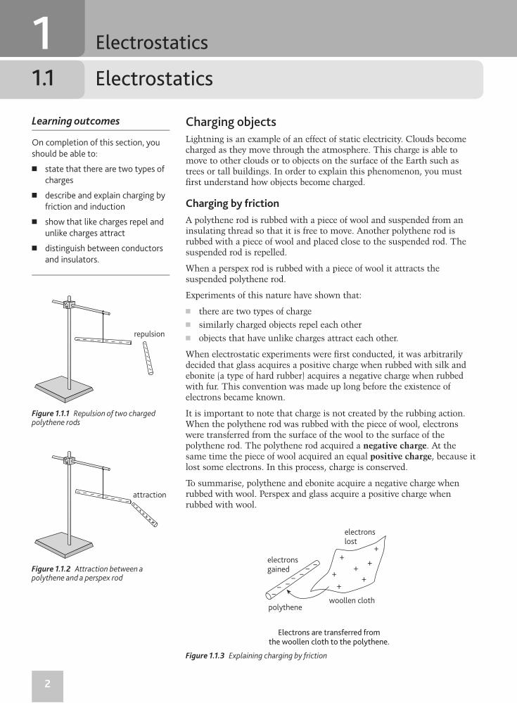
Charging by friction
A polythene rod is rubbed with a piece of wool and suspended from an insulating thread so that it is free to move. Another polythene rod is rubbed with a piece of wool and placed close to the suspended rod. The suspended rod is repelled.
When a perspex rod is rubbed with a piece of wool it attracts the suspended polythene rod.
Experiments of this nature have shown that:
� there are two types of charge
� similarly charged objects repel each other
� objects that have unlike charges attract each other.
When electrostatic experiments were fi rst conducted, it was arbitrarily decided that glass acquires a positive charge when rubbed with silk and ebonite (a type of hard rubber) acquires a negative charge when rubbed with fur. This convention was made up long before the existence of electrons became known.
It is important to note that charge is not created by the rubbing action. When the polythene rod was rubbed with the piece of wool, electrons were transferred from the surface of the wool to the surface of the polythene rod. The polythene rod acquired a negative charge. At the same time the piece of wool acquired an equal positive charge, because it lost some electrons. In this process, charge is conserved.
To summarise, polythene and ebonite acquire a negative charge when rubbed with wool. Perspex and glass acquire a positive charge when rubbed with wool.
Learning outcomes
On completion of this section, you
should be able to:
� state that there are two types of
charges
� describe and explain charging by
friction and induction
� show that like charges repel and
unlike charges attract
� distinguish between conductors
and insulators.
repulsion– –– –––– –
attraction–
–– ––––
–
electronsgained
polythene
electronslost
woollen cloth
Electrons are transferred fromthe woollen cloth to the polythene.
–
––
––
––
+
+
++
+
+
+
Figure 1.1.1 Repulsion of two charged polythene rods
Figure 1.1.2 Attraction between a polythene and a perspex rod
Figure 1.1.3 Explaining charging by friction
3
Chapter 1 Electrostatics
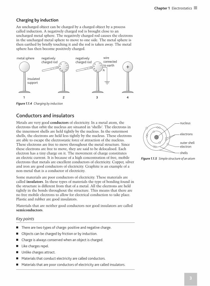
Charging by induction
An uncharged object can be charged by a charged object by a process called induction. A negatively charged rod is brought close to an uncharged metal sphere. The negatively charged rod causes the electrons in the uncharged metal sphere to move to one side. The metal sphere is then earthed by briefl y touching it and the rod is taken away. The metal sphere has then become positively charged.
metal sphere
insulatedsupport
negativelycharged rod
–– –
–
–––+
+++
wireconnectedto earth
negativelycharged rod
–– –
––+
+++
A+
1 2 3 4
nucleus
electrons
outer shellelectron
shells
Conductors and insulators
Metals are very good conductors of electricity. In a metal atom, the electrons that orbit the nucleus are situated in ‘shells’. The electrons in the innermost shells are held tightly by the nucleus. In the outermost shells, the electrons are held less tightly by the nucleus. These electrons are able to escape the electrostatic force of attraction of the nucleus. These electrons are free to move throughout the metal structure. Since these electrons are free to move, they are said to be delocalised. Each electron has a tiny charge on it. The movement of charge constitutes an electric current. It is because of a high concentration of free, mobile electrons that metals are excellent conductors of electricity. Copper, silver and iron are good conductors of electricity. Graphite is an example of a non-metal that is a conductor of electricity.
Some materials are poor conductors of electricity. These materials are called insulators. In these types of materials the type of bonding found in the structure is different from that of a metal. All the electrons are held tightly in the bonds throughout the structure. This means that there are no free mobile electrons to allow for electrical conduction to take place. Plastic and rubber are good insulators.
Materials that are neither good conductors nor good insulators are called semiconductors.
Key points
� There are two types of charge: positive and negative charge.
� Objects can be charged by friction or by induction.
� Charge is always conserved when an object is charged.
� Like charges repel.
� Unlike charges attract.
� Materials that conduct electricity are called conductors.
� Materials that are poor conductors of electricity are called insulators.
Figure 1.1.4 Charging by induction
Figure 1.1.5 Simple structure of an atom
4
1.2 Applications of electrostatics
Practical applications of electrostatics
Agricultural spraying
There are many problems associated with cultivating agricultural land. One such problem is pest control. Pests can be very harmful to development of the plants. They feed on the leaves of plants, usually living on the underside of the leaves. This makes spraying with pesticides a tricky process. A technique has been developed where the nozzle of the spray is connected to a high voltage supply. This high voltage supply has two effects. It charges the spray droplets positively and induces an opposite charge on the ground and the plants. This causes the spray droplets to be attracted to both sides of the leaves. This technique also prevents wastage during the spraying process.
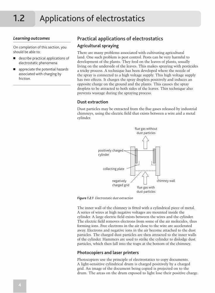
Dust extraction
Dust particles may be extracted from the fl ue gases released by industrial chimneys, using the electric fi eld that exists between a wire and a metal cylinder.
Learning outcomes
On completion of this section, you
should be able to:
� describe practical applications of
electrostatic phenomena
� appreciate the potential hazards
associated with charging by
friction.
flue gas without
dust particles
positively charged
cylinder
chimney wall
collecting plate
negatively
charged gridflue gas with
dust particles
Figure 1.2.1 Electrostatic dust extraction
The inner wall of the chimney is fi tted with a cylindrical piece of metal. A series of wires at high negative voltages are mounted inside the cylinder. A large electric fi eld exists between the wires and the cylinder. The electric fi eld removes electrons from some of the air molecules, thus forming ions. Free electrons in the air close to the wire are accelerated away. Electrons and negative ions in the air become attached to the dust particles. The charged dust particles are then attracted to the inner walls of the cylinder. Hammers are used to strike the cylinder to dislodge dust particles, which then fall into the traps at the bottom of the chimney.
Photocopiers and laser printers
Photocopiers use the principle of electrostatics to copy documents. A light-sensitive cylindrical drum is charged positively by a charged grid. An image of the document being copied is projected on to the drum. The areas on the drum exposed to light lose their positive charge.
5
Chapter 1 Electrostatics
A negatively charged powder, called the toner, is dusted over the drum. The toner is attracted to the positively charged image. A sheet of paper then receives a positive charge as it passes over the grid. The positively charged paper attracts toner from the drum and an image is formed on it. The image is made permanent by warming the fi nal product.
A laser printer operates using a similar principle. When the printer receives a digital version of the document to be printed, a laser uses a series of mirrors and lenses to focus it on the light-sensitive cylindrical drum. The image to be printed is written on the drum by the laser.
Electrostatic paint spraying
Most car manufacturers use electrostatics to paint their vehicles. As the paint leaves the nozzle of the sprayer, the droplets are given a charge. Since all the droplets have the same charge, they repel each other so that the paint spreads out to form a large even cloud. The body of the car is charged with an equal and opposite charge. The result is that the paint sticks to the surface of the car tightly and less paint is wasted in the process.
Hazards of static electricity
Static electricity can be very hazardous. There is always a danger of electric shock from charged objects. For example, our bodies may become charged by friction. Then touching a metal door handle causes the charge to fl ow to the handle. The fl ow of charge results in an electric current and you experience an electric shock. It is possible to see and hear a spark as you touch the door handle. Sometimes, it is possible to be charged up to many kilovolts.
Since there is always a danger of a spark being produced by electrostatics, great care must be taken when refuelling aircraft. A spark can ignite the fuel causing a dangerous explosion. A conducting cable is connected between the aircraft and the fuel tanker. This ensures that the aircraft and the fuel tanker are at the same electric potential. This ensures that no spark arises.
In thunderstorms, clouds are charged as they move through the atmosphere. These clouds have huge amounts of charge stored in them. When charge fl ows between clouds or towards tall buildings and trees, lightning is seen. Very large currents fl ow during this process. Lightning has been known to start fi res, damage buildings and even kill people by electrocution.
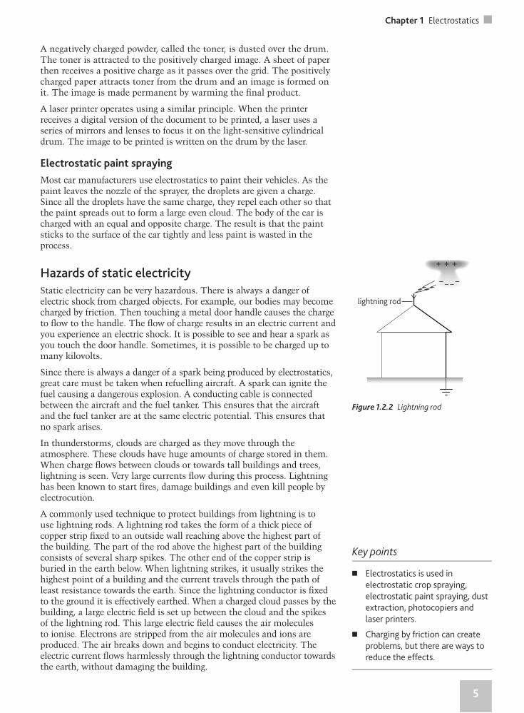
A commonly used technique to protect buildings from lightning is to use lightning rods. A lightning rod takes the form of a thick piece of copper strip fi xed to an outside wall reaching above the highest part of the building. The part of the rod above the highest part of the building consists of several sharp spikes. The other end of the copper strip is buried in the earth below. When lightning strikes, it usually strikes the highest point of a building and the current travels through the path of least resistance towards the earth. Since the lightning conductor is fi xed to the ground it is effectively earthed. When a charged cloud passes by the building, a large electric fi eld is set up between the cloud and the spikes of the lightning rod. This large electric fi eld causes the air molecules to ionise. Electrons are stripped from the air molecules and ions are produced. The air breaks down and begins to conduct electricity. The electric current fl ows harmlessly through the lightning conductor towards the earth, without damaging the building.
lightning rod
+ + +
– – – –
Figure 1.2.2 Lightning rod
Key points
� Electrostatics is used in
electrostatic crop spraying,
electrostatic paint spraying, dust
extraction, photocopiers and
laser printers.
� Charging by friction can create
problems, but there are ways to
reduce the effects.
6
2.1 Electric current and potential difference
2 Electrical quantities
Electric current and charge
Metals are good conductors of electricity. In a metal there are many atoms present. The outer shell electrons of the metal atoms are not tightly bound and are free to move throughout the lattice. Each electron carries a tiny amount of charge. When these charged particles (electrons) move in a particular direction, an electric current is produced. An electric current is the rate of fl ow of charged particles. The SI unit of electric current is the ampere (A).
When a salt such as sodium chloride is dissolved in water, sodium and chloride ions are produced. The ions present in the solution are charged. Therefore, a solution of sodium chloride will allow an electric current to fl ow through it.
Charged particles can have either a negative or a positive charge. The faster the charged particles move the greater the electric current.
The SI unit of charge is the coulomb (C). An electron has a charge of 1.6 × 10⁻¹⁹ C.
In order for the electrons in a metal to fl ow, energy must be supplied. In a simple circuit, an electric cell can be used to provide the energy needed to move the free electrons in the metal. The cell produces energy because of the chemical reactions taking place inside it.
Learning outcomes
On completion of this section, you
should be able to:
� understand that an electric
current is the fl ow of charge
� defi ne charge and the coulomb
� recall and use Q = It
� defi ne potential difference and
the volt
� recall and use V = W
Q.
componentammeter
I
Defi nition
An electric current is the rate of fl ow
of charge.
Equation
Q = It
Q – charge/C
I – current/A
t – time/s
Defi nition
1 coulomb is the quantity of charge
that passes through any section
of a conductor in 1 second when a
current of 1 ampere is fl owing.
1 C = 1 A s
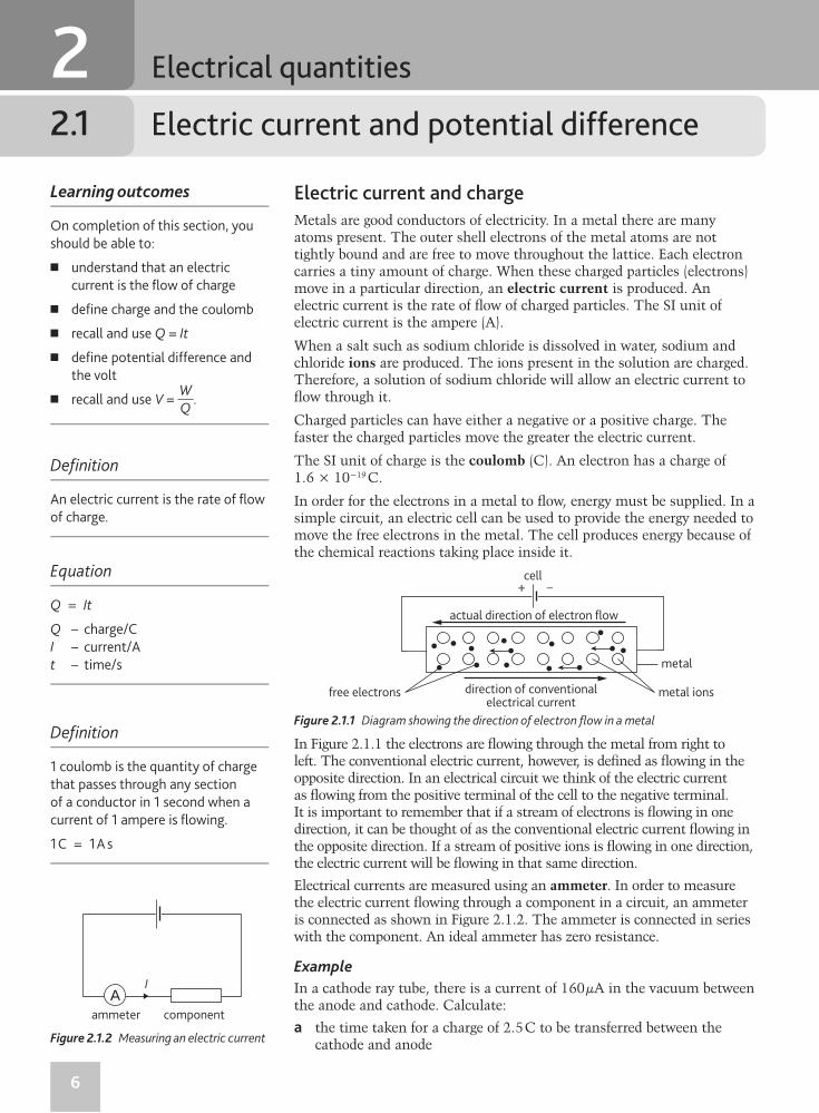
In Figure 2.1.1 the electrons are fl owing through the metal from right to left. The conventional electric current, however, is defi ned as fl owing in the opposite direction. In an electrical circuit we think of the electric current as fl owing from the positive terminal of the cell to the negative terminal. It is important to remember that if a stream of electrons is fl owing in one direction, it can be thought of as the conventional electric current fl owing in the opposite direction. If a stream of positive ions is fl owing in one direction, the electric current will be fl owing in that same direction.
Electrical currents are measured using an ammeter. In order to measure the electric current fl owing through a component in a circuit, an ammeter is connected as shown in Figure 2.1.2. The ammeter is connected in series with the component. An ideal ammeter has zero resistance.
Example
In a cathode ray tube, there is a current of 160 µA in the vacuum between the anode and cathode. Calculate:
a the time taken for a charge of 2.5 C to be transferred between the cathode and anode
actual direction of electron flow
cell
metal ions
metal
free electrons direction of conventionalelectrical current
+ –
Figure 2.1.1 Diagram showing the direction of electron fl ow in a metal
Fig ure 2.1.2 Measuring an electric current
7
Chapter 2 Electrical quantities
b the number of electrons emitted per second from the cathode.
(Charge on one electron e = –1.6 × 10⁻¹⁹ C)
a t = QI =
2.5160 × 10–6 = 1.56 × 10⁴ s
b Charge on one electron = e = –1.6 × 10⁻¹⁹ C
Charge fl owing per second = 160 µC
Number of electrons emitted per second = 160 × 10–6
1.6 × 10–19 = 1 × 10¹⁵
Potential difference
Whenever the term unit positive charge is used, it refers to +1 C of charge. Energy is required to move charge around an electrical circuit. A cell is usually required to power an electrical circuit. The cell converts chemical energy into electrical energy. When charge passes through components in a circuit, energy is converted from electrical to other forms of energy. In a fi lament lamp, electrical energy is converted into light and thermal energy. In the case of a resistor, electrical energy is converted into thermal energy.
An electric current fl ows from one point to another because of a difference in electric potential between the two points. The potential at a point in an electric fi eld is defi ned as the work done in moving unit positive charge from infi nity to that point. The SI unit of potential is the volt (V).
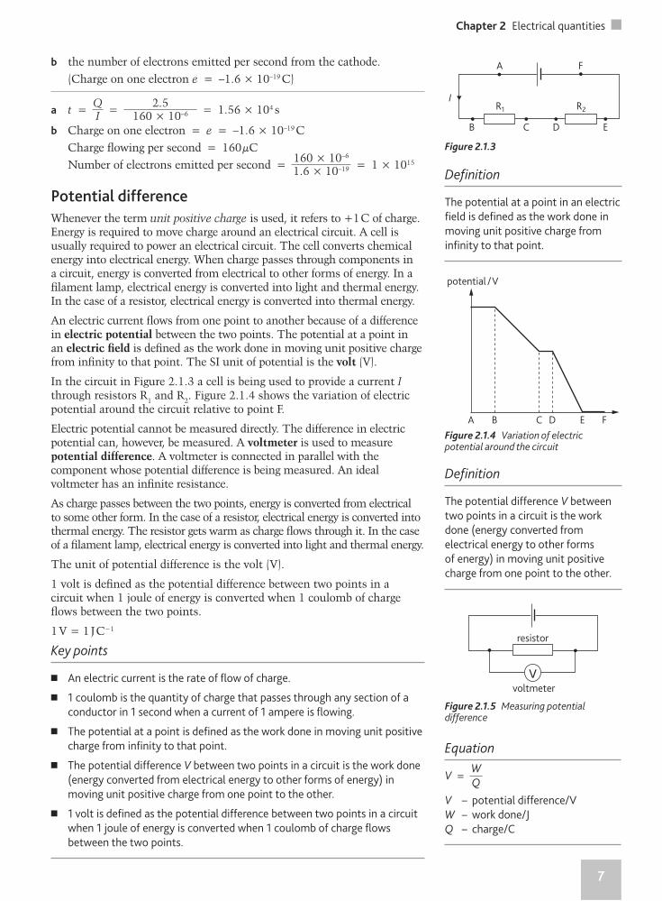
In the circuit in Figure 2.1.3 a cell is being used to provide a current I through resistors R1 and R2. Figure 2.1.4 shows the variation of electric potential around the circuit relative to point F.
Electric potential cannot be measured directly. The difference in electric potential can, however, be measured. A voltmeter is used to measure potential difference. A voltmeter is connected in parallel with the component whose potential difference is being measured. An ideal voltmeter has an infi nite resistance.
As charge passes between the two points, energy is converted from electrical to some other form. In the case of a resistor, electrical energy is converted into thermal energy. The resistor gets warm as charge fl ows through it. In the case of a fi lament lamp, electrical energy is converted into light and thermal energy.
The unit of potential difference is the volt (V).
1 volt is defi ned as the potential difference between two points in a circuit when 1 joule of energy is converted when 1 coulomb of charge fl ows between the two points.
1 V = 1 J C−1
Key points
� An electric current is the rate of fl ow of charge.
� 1 coulomb is the quantity of charge that passes through any section of a
conductor in 1 second when a current of 1 ampere is fl owing.
� The potential at a point is defi ned as the work done in moving unit positive
charge from infi nity to that point.
� The potential difference V between two points in a circuit is the work done
(energy converted from electrical energy to other forms of energy) in
moving unit positive charge from one point to the other.
� 1 volt is defi ned as the potential difference between two points in a circuit
when 1 joule of energy is converted when 1 coulomb of charge fl ows
between the two points.
IR1 R2
A F
B C D E
potential / V
A B C D E F
voltmeter
resistor
Figure 2.1.3
Figure 2.1.4 Variation of electric potential around the circuit
Figure 2.1.5 Measuring potential difference
Defi nition
The potential at a point in an electric
fi eld is defi ned as the work done in
moving unit positive charge from
infi nity to that point.
Defi nition
The potential difference V between
two points in a circuit is the work
done (energy converted from
electrical energy to other forms
of energy) in moving unit positive
charge from one point to the other.
Equation
V = W
Q
V – potential difference/V
W – work done/J
Q – charge/C
8
2.2 Drift velocity and power
Drift velocity
When there is no current fl owing in a metal, the electrons are moving about rapidly with a range of speeds, in random directions. When a potential difference is applied across a metal an electric fi eld is set up. The free electrons begin moving under the infl uence of the electric fi eld. As the free electrons accelerate they collide continuously with metal ions. This movement of the electrons is superimposed on the random motion. The drift velocity is the mean value of the velocity of the electrons in a conductor when an electric fi eld is applied.
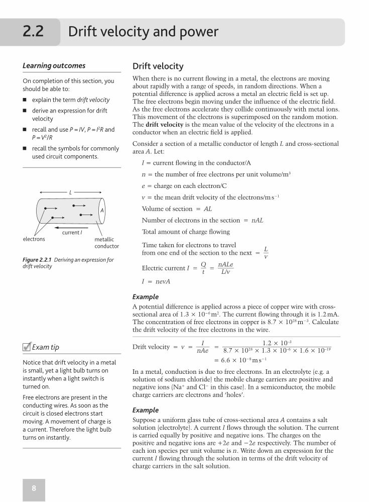
Consider a section of a metallic conductor of length L and cross-sectional area A. Let:
I = current fl owing in the conductor/A
n = the number of free electrons per unit volume/m3
e = charge on each electron/C
v = the mean drift velocity of the electrons/m s−1
Volume of section = AL
Number of electrons in the section = nAL
Total amount of charge fl owing
Time taken for electrons to travel from one end of the section to the next = L
v
Electric current I = Qt = nALe
L/v
I = nevA
Example
A potential difference is applied across a piece of copper wire with cross-sectional area of 1.3 × 10⁻⁶ m2. The current fl owing through it is 1.2 mA. The concentration of free electrons in copper is 8.7 × 1028 m−3. Calculate the drift velocity of the free electrons in the wire.
Drift velocity = v = InAe = 1.2 × 10⁻³
8.7 × 1028 × 1.3 × 10–6 × 1.6 × 10–19
= 6.6 × 10⁻⁸ m s−1
In a metal, conduction is due to free electrons. In an electrolyte (e.g. a solution of sodium chloride) the mobile charge carriers are positive and negative ions (Na+ and Cl− in this case). In a semiconductor, the mobile charge carriers are electrons and ‘holes’.
Example
Suppose a uniform glass tube of cross-sectional area A contains a salt solution (electrolyte). A current I fl ows through the solution. The current is carried equally by positive and negative ions. The charges on the positive and negative ions are +2e and −2e respectively. The number of each ion species per unit volume is n. Write down an expression for the current I fl owing through the solution in terms of the drift velocity of charge carriers in the salt solution.
Learning outcomes
On completion of this section, you
should be able to:
� explain the term drift velocity
� derive an expression for drift
velocity
� recall and use P = IV, P = I2R and
P = V2/R
� recall the symbols for commonly
used circuit components.
A
current I
L
metallicconductor
electrons
Figure 2.2.1 Deriving an expression for drift velocity
�Exam tip
Notice that drift velocity in a metal
is small, yet a light bulb turns on
instantly when a light switch is
turned on.
Free electrons are present in the
conducting wires. As soon as the
circuit is closed electrons start
moving. A movement of charge is
a current. Therefore the light bulb
turns on instantly.
9
Chapter 2 Electrical quantities
The positive and negative ions fl ow in opposite directions. Therefore, if the positive ions fl ow with a drift velocity v, the negative ions will fl ow with a drift velocity −v.
Current I = n(+2e)(v)(A) + n(−2e)(−v)(A) = 4nevA
Energy and power
Consider a steady current I, fl owing through a resistor R for a duration of time t. As current fl ows through the resistor it dissipates energy. The energy dissipated is equal to the potential energy lost by the charge as it moves through the potential difference between terminals of the resistor.
From the defi nition of potential difference
V = WQ
where
W is the energy dissipated in a time t
Q is the charge that fl owed during a time t
V is the potential difference across the resistor
The charge that fl ows during time t is Q = It
∴ W = ItV
Power is defi ned as the rate at which energy is converted.
P = Wt
∴ P = ItVt
P = IV
The SI unit of power is the watt (W).
From the defi nition of resistance (see 2.3)
V = IR
∴ P = I(IR) = I2R
Also, P = ( VR )V = V2
R
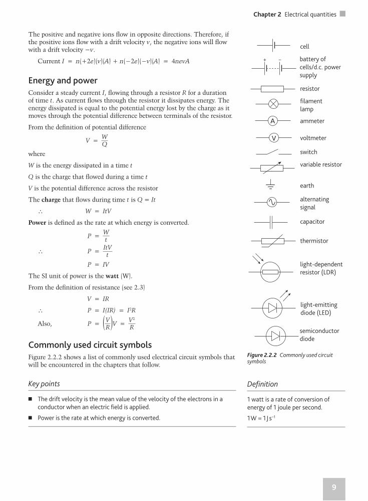
Commonly used circuit symbols
Figure 2.2.2 shows a list of commonly used electrical circuit symbols that will be encountered in the chapters that follow.
Key points
� The drift velocity is the mean value of the velocity of the electrons in a
conductor when an electric fi eld is applied.
� Power is the rate at which energy is converted.
Figure 2.2.2 Commonly used circuit symbols
+ –
Defi nition
1 watt is a rate of conversion of
energy of 1 joule per second.
1 W = 1 J s−1
cell
battery of
cells/d.c. power
supply
resistor
fi lament
lamp
ammeter
voltmeter
switch
variable resistor
earth
alternating
signal
capacitor
thermistor
light-dependent
resistor (LDR)
light-emitting
diode (LED)
semiconductor
diode
10
2.3 Resistance
Resistance
In a metal, there are free electrons throughout the structure. These electrons are free to move within the metal. When a cell is connected across the ends of a piece of metal, the electrons begin moving. The cell provides the necessary energy to allow the electrons to move. As the electrons move through the metal they collide with each other and the metal ions. These collisions restrict the fl ow of electrons. This property of the metal is known as electrical resistance.
The circuit in Figure 2.3.1 is used to determine the resistance of the component X. The component in this case is a resistor. The voltmeter reading gives the potential difference across the resistor. The ammeter reading gives the current fl owing through the resistor. The ratio of the potential difference to the current fl owing through component X is its resistance.
Defi nition
Resistance (R) is defi ned as the ratio of the potential difference (V) across the
conductor to the current (I) fl owing through it.
Equation
R = V
I
R – resistance/ΩV – potential difference/V
I – current/A
The SI unit of resistance is the ohm (Ω).
Current–voltage graphs
In the circuit in Figure 2.3.2 a variable resistor is used to adjust the current fl owing through the component X.
The variable resistor is adjusted and several values of V and the corresponding values of I are recorded. A graph of I against V is then plotted to obtain the I–V characteristic of the component.
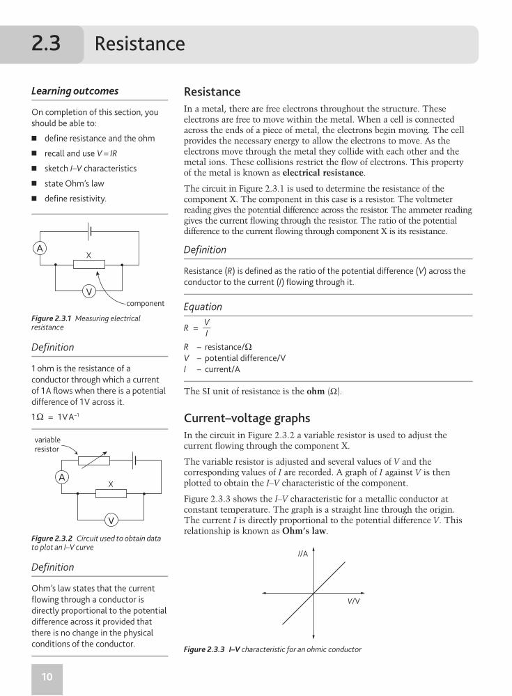
Figure 2.3.3 shows the I–V characteristic for a metallic conductor at constant temperature. The graph is a straight line through the origin. The current I is directly proportional to the potential difference V. This relationship is known as Ohm’s law.
Learning outcomes
On completion of this section, you
should be able to:
� defi ne resistance and the ohm
� recall and use V = IR
� sketch I–V characteristics
� state Ohm’s law
� defi ne resistivity.
component
X
variableresistor
X
V/V
I/A
Figure 2.3.1 Measuring electrical resistance
Figure 2.3.3 I–V characteristic for an ohmic conductor
Figure 2.3.2 Circuit used to obtain data to plot an I–V curve
Defi nition
1 ohm is the resistance of a
conductor through which a current
of 1 A fl ows when there is a potential
difference of 1 V across it.
1 Ω = 1 V A−1
Defi nition
Ohm’s law states that the current
fl owing through a conductor is
directly proportional to the potential
difference across it provided that
there is no change in the physical
conditions of the conductor.
11
Chapter 2 Electrical quantities
A conductor that obeys Ohm’s law is called ‘ohmic’.
The physical conditions could be temperature or mechanical strain.
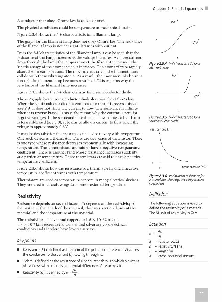
Figure 2.3.4 shows the I–V characteristic for a fi lament lamp.
The graph for the fi lament lamp does not obey Ohm’s law. The resistance of the fi lament lamp is not constant. It varies with current.
From the I–V characteristics of the fi lament lamp it can be seen that the resistance of the lamp increases as the voltage increases. As more current fl ows through the lamp the temperature of the fi lament increases. The kinetic energy of the atoms inside it increases. The atoms vibrate rapidly about their mean positions. The moving electrons in the fi lament lamp collide with these vibrating atoms. As a result, the movement of electrons through the fi lament lamp becomes restricted. This explains why the resistance of the fi lament lamp increases.
Figure 2.3.5 shows the I–V characteristic for a semiconductor diode.
The I–V graph for the semiconductor diode does not obey Ohm’s law. When the semiconductor diode is connected so that it is reverse-biased (see 8.3) it does not allow any current to fl ow. The resistance is infi nite when it is reverse-biased. This is the reason why the current is zero for negative voltages. If the semiconductor diode is now connected so that it is forward-biased (see 8.3), it begins to allow a current to fl ow when the voltage is approximately 0.6 V.
It may be desirable for the resistance of a device to vary with temperature. One such device is a thermistor. There are two kinds of thermistor. There is one type whose resistance decreases exponentially with increasing temperature. These thermistors are said to have a negative temperature coeffi cient. There is another kind whose resistance increases suddenly at a particular temperature. These thermistors are said to have a positive temperature coeffi cient.
Figure 2.3.6 shows how the resistance of a thermistor having a negative temperature coeffi cient varies with temperature.
Thermistors are used as temperature sensors in many electrical devices. They are used in aircraft wings to monitor external temperature.
Resistivity
Resistance depends on several factors. It depends on the resistivity of the material, the length of the material, the cross-sectional area of the material and the temperature of the material.
The resistivities of silver and copper are 1.6 × 10⁻⁸ Ω m and 1.7 × 10⁻⁸ Ω m respectively. Copper and silver are good electrical conductors and therefore have low resistivities.
Key points
� Resistance (R) is defi ned as the ratio of the potential difference (V) across
the conductor to the current (I) fl owing through it.
� 1 ohm is defi ned as the resistance of a conductor through which a current
of 1 A fl ows when there is a potential difference of 1 V across it.
� Resistivity (ρ) is defi ned by R = ρL
A.
V/V
I/A
V/V
I/A
temperature / °C
resistance / Ω
Figure 2.3.4 I–V characteristic for a fi lament lamp
Figure 2.3.5 I–V characteristic for a semiconductor diode
Figure 2.3.6 Variation of resistance for a thermistor with negative temperature coeffi cient
Defi nition
The following equation is used to
defi ne the resistivity of a material.
The SI unit of resistivity is Ω m.
Equation
R = ρL
A
R – resistance/Ωρ – resistivity/Ω m
L – length/m
A – cross-sectional area/m2
12
2.4 Electromotive force and internal resistance
Electromotive force (e.m.f.) and internal resistance
In an electrical circuit, a source provides the energy required to drive an electric current in the circuit. The source has a positive and a negative terminal. Electrons are forced out of the negative terminal in a closed circuit. Examples of sources include cells, batteries, solar cells and dynamos.
In a cell, chemical energy is converted into electrical energy. The electromotive force (e.m.f.) of a cell is the energy converted from chemical energy to electrical energy per unit charge fl owing through the cell. In 2.1, potential difference was defi ned as energy converted from electrical energy to other forms of energy per unit charge fl owing between two points.
Learning outcomes
On completion of this section, you
should be able to:
� understand the difference
between potential difference and
e.m.f.
� understand the concept of
internal resistance.
cell
rE
internalresistance
Defi nition
The e.m.f. of a source is defi ned
as the energy converted from
chemical (or mechanical) energy
into electrical energy per unit charge
fl owing through it.
�Exam tip
1 e.m.f. is associated with active
devices (e.g. batteries) that
produce electrical power.
2 Potential difference is associated
with passive devices (e.g. resistors).
3 Potential difference is also
associated with electric fi elds
(see 4.1).
Figure 2.4.1 e.m.f. and internal resistance
Figure 2.4.2
rE
I
R
A B
V
Equation
V = W
Q
V – electromotive force, e.m.f./V
W – work done/J
Q – charge/C
Defi nition
The potential difference between
two points in a circuit is the energy
converted from electrical energy
to other forms of energy (e.g. heat)
per unit charge fl owing between the
two points.
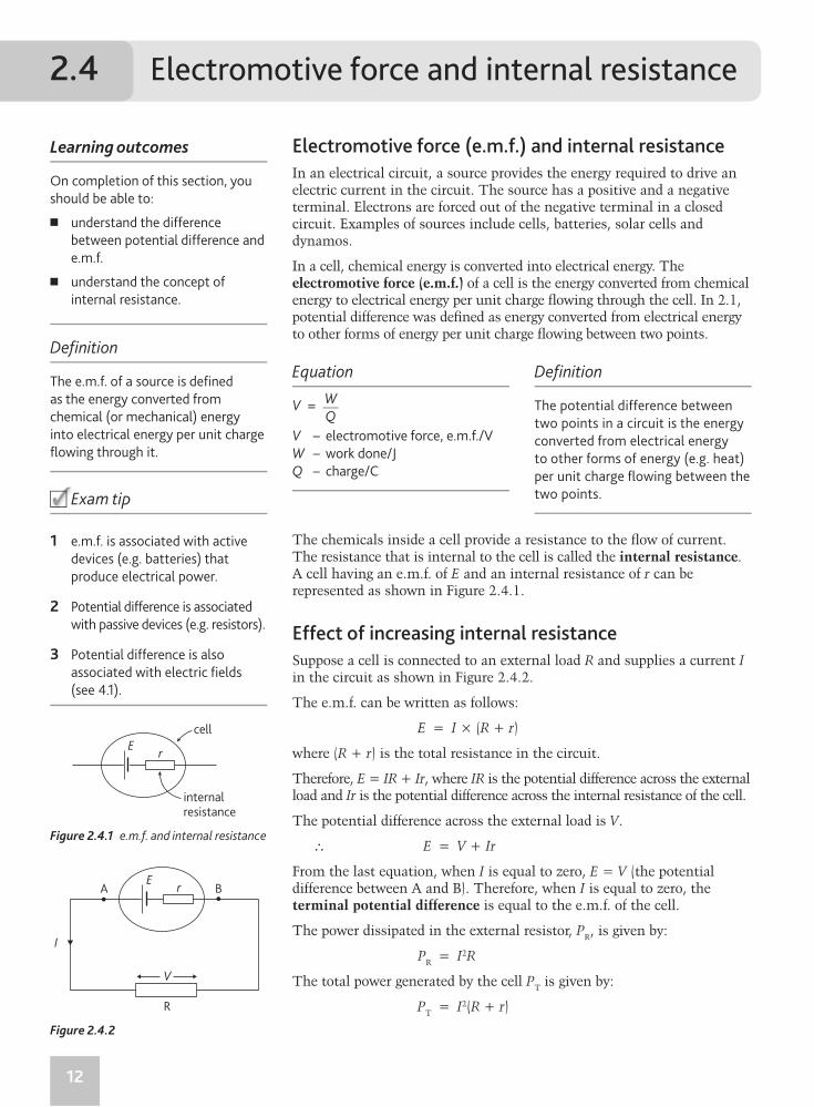
The chemicals inside a cell provide a resistance to the fl ow of current. The resistance that is internal to the cell is called the internal resistance. A cell having an e.m.f. of E and an internal resistance of r can be represented as shown in Figure 2.4.1.
Effect of increasing internal resistance
Suppose a cell is connected to an external load R and supplies a current I in the circuit as shown in Figure 2.4.2.
The e.m.f. can be written as follows:
E = I × (R + r)
where (R + r) is the total resistance in the circuit.
Therefore, E = IR + Ir, where IR is the potential difference across the external load and Ir is the potential difference across the internal resistance of the cell.
The potential difference across the external load is V.
∴ E = V + Ir
From the last equation, when I is equal to zero, E = V (the potential difference between A and B). Therefore, when I is equal to zero, the terminal potential difference is equal to the e.m.f. of the cell.
The power dissipated in the external resistor, PR, is given by:
PR = I2R
The total power generated by the cell PT is given by:
PT = I2(R + r)
13
Chapter 2 Electrical quantities
The fraction of the total power dissipated in the external resistor is given by:
PR
PT
= I2RI2(R + r)
PR
PT
= R(R + r)
After prolonged use, the internal resistance of a cell may increase. The increased internal resistance reduces the maximum current that the cell can supply. This reduces the total power PT. This reduces the fraction of the total power supplied to the resistor R. As a result, the power supplied to R is reduced.
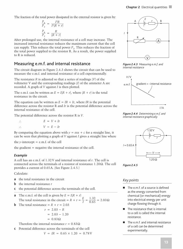
Measuring e.m.f. and internal resistance
The circuit diagram in Figure 2.4.3 shows the circuit that can be used to measure the e.m.f. and internal resistance of a cell experimentally.
The resistance R is adjusted so that a series of readings (V) of the voltmeter V and the corresponding readings (I) of the ammeter A are recorded. A graph of V against I is then plotted.
The e.m.f. can be written as E = I(R + r), where (R + r) is the total resistance in the circuit.
The equation can be written as E = IR + Ir, where IR is the potential difference across the resistor R and Ir is the potential difference across the internal resistance of the cell.
The potential difference across the resistor R is V.
∴ E = V + Ir
∴ V = E − Ir
By comparing the equation above with y = mx + c for a straight line, it can be seen that plotting a graph of V against I gives a straight line where
the y-intercept = e.m.f. of the cell
the gradient = negative the internal resistance of the cell.
Example
A cell has an e.m.f. of 1.32 V and internal resistance of r. The cell is connected across the terminals of a resistor of resistance 1.20 Ω. The cell provides a current of 0.65 A. (See Figure 2.4.5.)
Calculate:
a the total resistance in the circuit
b the internal resistance r
c the potential difference across the terminals of the cell.
a The e.m.f. of the cell is given by E = I(R + r)
The total resistance in the circuit = R + r = EI = 1.320.65 = 2.03 Ω
b The total resistance = R + r = 2.03
r = 2.03 − R
= 2.03 − 1.20
= 0.83 Ω Therefore the internal resistance r = 0.83 Ωc Potential difference across the terminals of the cell
V = IR = 0.65 × 1.20 = 0.78 V
rE
I
R
A B
V / V
e.m.f.
I / A
gradient = – internal resistance
r
I = 0.65 A
1.20 Ω
V
1.32 V
Figure 2.4.3 Measuring e.m.f. and internal resistance
Figure 2.4.4 Determining e.m.f. and internal resistance graphically
Figure 2.4.5
Key points
� The e.m.f. of a source is defi ned
as the energy converted from
chemical (or mechanical) energy
into electrical energy per unit
charge fl owing through it.
� The resistance that is internal
to a cell is called the internal
resistance.
� The e.m.f. and internal resistance
of a cell can be determined
experimentally.
CAPE
®
CAPE
®
PhysicsPhysicsPhysicsPhysicsPhysicsPhysicsPhysicsPhysicsPhysicsPhysicsPhysicsPhysicsPhysicsPhysicsPhysicsPhysicsPhysicsPhysicsPhysicsPhysicsPhysicsPhysicsPhysicsPhysicsPhysicsPhysicsPhysics
UNIT 2
A Caribbean Examinations Council® Study Guide
UN
IT 2UNIT 2
CAPE
®
A Caribbean Examinations Council® Study Guide
Developed exclusively with the Caribbean Examinations Council (CXC®), this study guide will provide candidates in and out of school with additional support to maximise their performance in CAPE® Physics Unit 2.
Written by an experienced team comprising teachers and experts in the CAPE® Physics Unit 2 syllabus and examination, this study guide covers the elements of the syllabus that you must know in an easy-to-use double-page format. Each topic begins with the key learning outcomes from the syllabus and contains a range of features designed to enhance your study of the subject, such as:
• Examination-style practice questions to build confi dence ahead of your examinations
• Exam tips with useful advice to help you succeed in your examinations
• Defi nitions providing succinct explanations of essential terms.
This comprehensive self-study package includes a fully interactive CD, incorporating multiple-choice questions and sample examination answers with accompanying examiner feedback, to build your skills and confi dence as you prepare for the CAPE® Physics Unit 2 examination.
The Caribbean Examinations Council (CXC®) has worked exclusively with Nelson Thornes to produce a series of Study Guides across a wide range of subjects at CCSLC®, CSEC® and CAPE®. Developed by expert teachers and resource persons, these Study Guides have been designed to help students reach their full potential as they study their CXC® programme.
Physics A C
aribbean Examinations Council®
Study Guide
ISBN 978-1-4085-1764-2
9 781408 517642
Related Documents