A C Reference Implementation of the LonTalk ® Protocol on the MC68360 Document Revision 1.7 Revision Date: July 15, 1998 Code Version 1.7 Adept Systems Incorporated www.adeptsystemsinc.com Boca Raton, FL 33428-4861 +1-561-487-1244 (tel) +1-561-487-8930 (fax) [email protected] [email protected]

Welcome message from author
This document is posted to help you gain knowledge. Please leave a comment to let me know what you think about it! Share it to your friends and learn new things together.
Transcript

A C Reference Implementation of the LonTalk® Protocol on the MC68360
Document Revision 1.7
Revision Date: July 15, 1998
Code Version 1.7
Adept Systems Incorporated
www.adeptsystemsinc.com Boca Raton, FL 33428-4861
+1-561-487-1244 (tel) +1-561-487-8930 (fax)

Section
TABLE OF CONTENTS
Section 1 Overview. . . . . . . . . . . . . . . . . . . . . . . . . . . . . . . . . . . . . . . . . . . . . . . . . . . . . . . . . . 3
Section 1.1 Objectives of Reference Implementation. . . . . . . . . . . . . . . . . . . . . . . . . . . . . 3
Section 1.2 Development Team . . . . . . . . . . . . . . . . . . . . . . . . . . . . . . . . . . . . . . . . . . . . . 4
Section 1.3 Development Tools . . . . . . . . . . . . . . . . . . . . . . . . . . . . . . . . . . . . . . . . . . . . . 5
Section 1.4 Development History . . . . . . . . . . . . . . . . . . . . . . . . . . . . . . . . . . . . . . . . . . . . 5
Section 1.5 Coding Conventions. . . . . . . . . . . . . . . . . . . . . . . . . . . . . . . . . . . . . . . . . . . . . 6
Section 2 Reference Implementation Software Architecture . . . . . . . . . . . . . . . . . . . . . . . . . 11
Section 2.1 Queues . . . . . . . . . . . . . . . . . . . . . . . . . . . . . . . . . . . . . . . . . . . . . . . . . . . . . . 12
Section 2.2 Software Timers . . . . . . . . . . . . . . . . . . . . . . . . . . . . . . . . . . . . . . . . . . . . . . . 17
Section 2.3 Pragmas . . . . . . . . . . . . . . . . . . . . . . . . . . . . . . . . . . . . . . . . . . . . . . . . . . . . . 17
Section 2.4 Memory Allocation . . . . . . . . . . . . . . . . . . . . . . . . . . . . . . . . . . . . . . . . . . . . 17
Section 2.5 Data Structures. . . . . . . . . . . . . . . . . . . . . . . . . . . . . . . . . . . . . . . . . . . . . . . . 17
Section 2.6 Features . . . . . . . . . . . . . . . . . . . . . . . . . . . . . . . . . . . . . . . . . . . . . . . . . . . . . 18
Section 3 MC68360 Implementation . . . . . . . . . . . . . . . . . . . . . . . . . . . . . . . . . . . . . . . . . . . 23
Section 3.1 Special Purpose Mode . . . . . . . . . . . . . . . . . . . . . . . . . . . . . . . . . . . . . . . . . . 23
Section 3.2 Direct Mode (Single Ended) . . . . . . . . . . . . . . . . . . . . . . . . . . . . . . . . . . . . . 28
Section 4 Application Programmer’s Interface (API) Description . . . . . . . . . . . . . . . . . . . . . 32
Section 4.1 Overview . . . . . . . . . . . . . . . . . . . . . . . . . . . . . . . . . . . . . . . . . . . . . . . . . . . . 32
Section 4.2 Compilation . . . . . . . . . . . . . . . . . . . . . . . . . . . . . . . . . . . . . . . . . . . . . . . . . . 29
Section 4.3 Pragmas . . . . . . . . . . . . . . . . . . . . . . . . . . . . . . . . . . . . . . . . . . . . . . . . . . . . . 32
Section 4.4 Initialization . . . . . . . . . . . . . . . . . . . . . . . . . . . . . . . . . . . . . . . . . . . . . . . . . . 35
Section 4.5 Reset. . . . . . . . . . . . . . . . . . . . . . . . . . . . . . . . . . . . . . . . . . . . . . . . . . . . . . . . 32
Section 4.6 Application Program . . . . . . . . . . . . . . . . . . . . . . . . . . . . . . . . . . . . . . . . . . . 35
Section 4.7 Explicit Messages and Responses . . . . . . . . . . . . . . . . . . . . . . . . . . . . . . . . . 36
Section 4.8 Network Variables . . . . . . . . . . . . . . . . . . . . . . . . . . . . . . . . . . . . . . . . . . . . . 40
Section 4.9 Network Variable Related Functions . . . . . . . . . . . . . . . . . . . . . . . . . . . . . . . 42
Section 4.10 Network Variables and Address Table Entries . . . . . . . . . . . . . . . . . . . . . . . 39
Section 4.11 Message Tags . . . . . . . . . . . . . . . . . . . . . . . . . . . . . . . . . . . . . . . . . . . . . . . . 39
Section 4.12 Miscellaneous Functions . . . . . . . . . . . . . . . . . . . . . . . . . . . . . . . . . . . . . . . 42
Section 4.13 Alias Tables . . . . . . . . . . . . . . . . . . . . . . . . . . . . . . . . . . . . . . . . . . . . . . . . . 40
Section 4.14 Software Timers . . . . . . . . . . . . . . . . . . . . . . . . . . . . . . . . . . . . . . . . . . . . . . 43
Section 5 References. . . . . . . . . . . . . . . . . . . . . . . . . . . . . . . . . . . . . . . . . . . . . . . . . . . . . . . . 45
– 2 –
Section 1
1 OVERVIEW
This document describes the “C” language reference implementation of the LonTalk* protocolon the MC68360. The objectives of the reference implementation are described along with theapproach taken in its development. The software architecture is described along with the relevantdetails associated with implementation on a 68360. The API for the reference implementation isalso given.
1.1 Objectives of Reference Implementation
1.1.1 Support Open Protocol Specification— In the past the only available implementation of theLonTalk® protocol was on a Neuron® processor. Recently however, Echelon® Corporation hasmade the LonTalk protocol open for implementation on any processor. In an effort to facilitatemore rapid implementation and porting to other processors, Echelon®* Corporation has contractedwith Adept Systems to develop and document a working C language implementation on anMC68360 as the basis for a open protocol specification. LonTalk is under consideration for adop-tion as a standard protocol by several industrial control standards organizations. An essentialrequirement for many of these standards bodies is a complete open specification of the protocol.The existing LonTalk Protocol Specification document published by Echelon contains onlypseudo-code and is not a complete self-contained specification. One of the goals of referenceimplementation is to expand and clarify the specification with the addition of working C code.The reference implementation was developed from a functional description only of the LonTalkprotocol. No Neuron® C or Neuron assembly source code was provided for reference. Because ofthis “clean” approach to the reference implementation development, omissions, confusingdescriptions, and errors in the original protocol specification became more apparent. As a result alist of clarifying questions and answers has been compiled for future reference.
1.1.2 Clarity and Understandability vs. Performance— Because the reference implementation’smain purpose is to support an open protocol specification the emphasis was put on developingclear, correct, and understandable code as opposed to optimally performing code relative to speedand memory. The implementation minimizes dependence on the features of a specific develop-ment environment or operating system services or additional external hardware. For example, thereference implementation does not use a real time operating system (RTOS) but has built in itsown scheduling and timing facilities. In every case where possible ANSI C language code wasused instead of assembly. In fact, there is only one line of assembly code in the reference imple-mentation. The behavior of the Neuron® processor is the “gold” standard for correct behavior ofthe implementation.
1.1.3 Readability— A set of coding conventions has been adopted that emphasize readability anddocumentation. The coding conventions help to maintain consistency throughout the code. Theconventions used were based on a combination of recommendations from well known C stylemanuals and the development teams preferences.
1.1.4 Neuron® Memory Map Emulation— A virtual memory map of the Neuron Chip’s 64k mem-ory space is maintained in a global structure. This approach makes it easier for the reference
*. Echelon, LON, LONWORKS, LonBuilder, NodeBuilder, LonManager, LonTalk, LonUsers, Neuron, 3120, 3150, the Echelon logo, and the LonUsers logo are trademarks of Echelon Corporation registered in the United States and other countries. LonLink, LonResponse, LonSupport, LonMaker, and LonPoint are trademarks of Echelon Corporation.
– 3 –
Section 1.2
implementation to replicate Neuron® chip facilities for reading and writing memory to set config-uration parameters in response to network management messages.
1.1.5 Data Flow Architecture— The software design developed by Adept is driven by the objec-tives stated above. A data flow style architecture was selected where the layers execute in roundrobin fashion and pass information from layer to layer with global memory queues. The providesa clearer separation of functionality in the layers than would a function call stack thereby enhanc-ing understandability.The data flow approach also simplifies the implementation by avoidingfunction blocking for timers to expire and/or complex function return handling. This approachalso makes it easier to port the implementation to other processors and/or a multi-process RTOSwhere each layer could be its own process and communicates through either shared memory ormessage queues.
1.1.6 68360 Microcontroller— The microprocessor hardware selected by Echelon for the refer-ence implementation is the Motorola MC68360 quad integrated communications controller. The68360 has a 32 bit processor core and a multifunction communications processor module. Thecommunications processor includes many of the functions needed to implement the media accesscontrol layer of the LonTalk protocol. Because of the 68360’s built in support for several otherprotocols it has potential as a generic platform for building gateways between LonTalk and otherprotocols such as TCP/IP-Ethernet. It was hoped that no external hardware would be required toimplement the LonTalk protocol on the 68360. As of this writing, however, several hardwaredesign features of the 68360 are incompatible with the direct mode of the LonTalk protocol. Thisdocument describes the finished implementation of special purpose mode only.
1.1.7 Future Protocol Ports— One other requirement is that Adept Systems be positioned in thefuture to do ports of the LonTalk Protocol to other platforms or provide consulting services to oth-ers doing ports.
1.2 Development Team
Dr. Samuel Smith and Dr. Stanley Dunn founded Adept Systems in 1994 to commercialize intelli-gent, distributed control system technology and expertise developed at Florida Atlantic University(FAU). The FAU Advanced Marine Systems Group, under the direction of Dr. Smith and Dr.Dunn, has developed this technology and expertise over the past six years as the result of a multi-million dollar research program to develop autonomous underwater vehicles (AUV), sensor sys-tems, and shipboard automation. A key factor in this successful research has been the creation of amodular, low-cost reconfigurable AUV architecture that uses the LONWORKS® technology.
For the purpose of this proposed work, Adept has assembled a very capable development team.The 3 primary members of this team are Samuel Smith, K. Ganesan, and Bryan Jacobson. In addi-tion to the 3 principles members the development team will be supplemented by staff and gradu-ate students at FAU who will be hired on a contract basis as needed.
Dr. Smith is the project leader. His primary technical participation is focused on the physical andlink layers with emphasis on the processor and electronic hardware specific implementationissues. He has a Ph.D. in electrical and computer engineering and is experienced in embeddedcontrollers, and has over 4 years experience with LONWORKS® development and 10+ years experi-ence in C programming. Dr. Ganesan’s primary technical participation will focus on the network,transport, and session layers in addition to the overall architecture. He has a Ph.D. in computerscience and is experienced in networking, real time operating systems, and database design with
– 4 –
Section 1.3
12+ years of experience in C programming. Mr. Jacobson’s primary technical participation willfocus on the presentation and application layers and in code integration, testing, and validation.He has an M.S. in Computer Science and is experienced in portability, portability testing and val-idation, and compiler15+ design with 15+ years experience in C language programming.
1.3 Development Tools
The major components to the development environment include an Arnewsh SBC360-1M devel-opment board, Software Development System’s (SDS) CrossCode 68K C Compiler Suite andSingleStep C BDM Debugger.
The SBC360 has a 25 MHz MC68EN360 processor with 1 Mbyte of DRAM, on-board ROMmonitor/debugger, Ethernet port, serial cable, BDM port, and documentation. The board requiresan external 5 Volt power supply. The SDS development environment runs in Windows95/NT andincludes a software simulator of the 68360. The SBC360 sells for $975. The SDS compiler doesnot include a make facility. We use the Gnu Software Foundation make utility. It can be obtainedby ftp from ftp.prep.ai.mit.edu/make-3.75.tar.gz. A C compiler such as Visual C is needed to buildthe make utility. A pre-compiled version is provided with the reference implementation. The SDScompiler includes a limited text editor but will work with a more full featured editor such asEMACS. The CrossCode C compiler is $2000 and the SingleStep BDM debugger is $2500. Thedebugger comes with a cable to connect the BDM port to a PC parallel port. Contact informationis listed below.
Arnewsh Inc.P.O. Box 270352Fort Collins, CO 80527-0352Tel: 970-223-1616 Fax: 970-223-9573
Software Development Systems815 Commerce, Suite 250Oak Brook, Illinois 60521Tel: 800-448-7733 or 630-368-0400 Fax: 630-990-4641
1.4 Development History
Because the reference implementation was developed from a functional description of the proto-col specification, the first few weeks of the project involved extensive review and clarification ofthe protocol specification document through a combination of phone, email, and in personexchanges between Echelon and Adept [Echelon 95]. A history of the Q&A exchanges has beencompiled. The initial software architecture was then designed. The coding tasks were divided intothree groups, the MAC layer, the middle layers 2 – 6, and layer 7 including the API. Coding pro-ceeded in parallel on these 3 groups. Modifications and revisions to the architecture were made asappropriate as understanding and the implementation matured. Before the MAC layer was fin-ished it was desirable to test the completed parts of the middle layers. To do this the protocol stackwas modified to allow multiple protocol stacks to run on a single processor with a software virtualchannel connecting the stacks. This greatly sped the testing of the middle and upper layers of thereference implementation.
Clarifications on 68360 functionality were provided by one of the Motorola field sales representa-tives. At first study it appeared that there might be a few problems in implementing the directmode on the 68360 without external hardware. As a result the initial development focused on
– 5 –

Section 1.5
implementing the special purpose mode while waiting for help and clarification from Motorola.The goal was to implement a skeleton stack that supported at least one physical layer interface,one protocol service type and one message type. The technical challenge for the special purposemode was to implement continuous transfers of frames between the 68360 and the transceiver. Acombination of functionality in the transceiver and 68360 make is impossible to implement con-tinuous transfers. Instead a non-continuous mode was implemented with the addition of some lim-ited external hardware. Details are given below in Sec. 3. This allowed the upper layers tocommunicate with Neuron Chips and facilitated further development and testing of the upper lay-ers. Once the basic special purpose mode was working, development resumed on the direct mode.Several discrepancies between the actual and documented function of the 68360 in transparentmode became problematic with regards to implementing direct mode. Development resumed onthe channel access algorithm for special purpose mode which was subsequently completed.
1.5 Coding Conventions
The Coding conventions and examples are given below.
File Naming File names are all in lower case. The name reflects the purpose of its use. For example, network.c or session.c. To facilitate use with DOS systems, we will restrict our filename length to 8 characters.
.c and .h files Every .c file will have a corresponding .h file that represents the public interface except main.c that contains main.
Every .h file has the following information:
1) constant definitions (#define) 2) macro definitions 3) type definitions 4) global variable declarations (i.e extern declarations) 5) functions prototypes
Only prototypes for functions that are visible outside of the .c file should be given the prototypes in the .h file.
All functions which are used locally inside the .c file should be declared as static so that there is no conflict with same names from other files.
Global variables used only in the .c file should be declared as static. Only those global variables that are declared in the .c file and visible outside should be given the extern declaration in the .h file.
Each function prototype should be preceded by a comment that gives information about the proper usage of the function. The function prototype should be the same as the function heading in the .c file.
– 6 –
Section 1.5
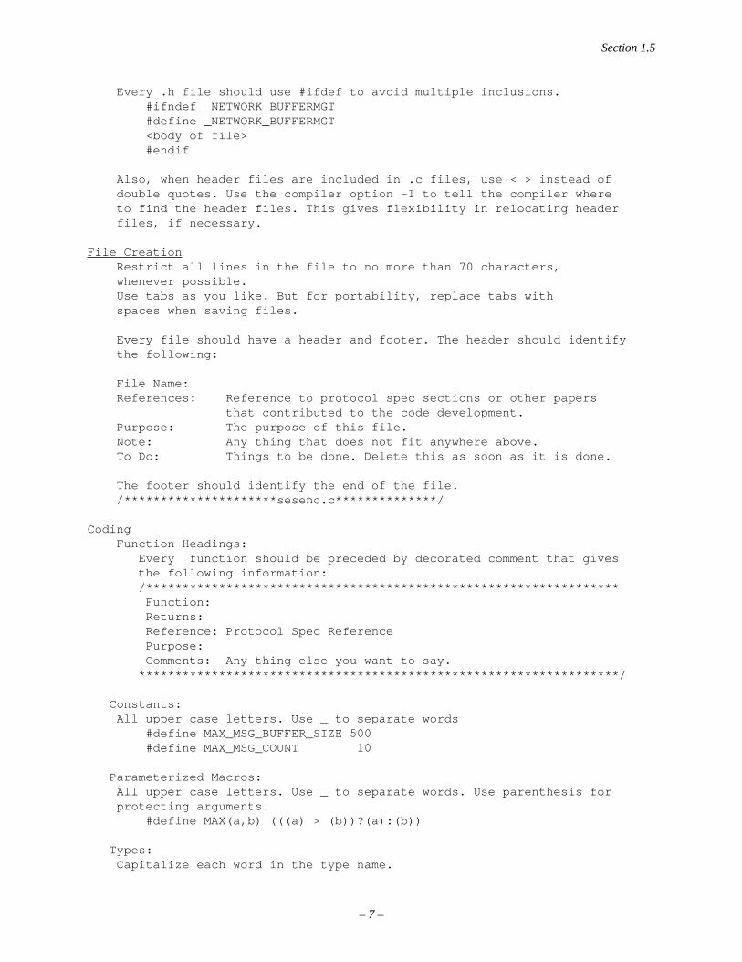
Every .h file should use #ifdef to avoid multiple inclusions. #ifndef _NETWORK_BUFFERMGT #define _NETWORK_BUFFERMGT <body of file> #endif
Also, when header files are included in .c files, use < > instead of double quotes. Use the compiler option -I to tell the compiler where to find the header files. This gives flexibility in relocating header files, if necessary.
File Creation Restrict all lines in the file to no more than 70 characters, whenever possible. Use tabs as you like. But for portability, replace tabs with spaces when saving files.
Every file should have a header and footer. The header should identify the following:
File Name: References: Reference to protocol spec sections or other papers that contributed to the code development. Purpose: The purpose of this file. Note: Any thing that does not fit anywhere above. To Do: Things to be done. Delete this as soon as it is done.
The footer should identify the end of the file. /*********************sesenc.c**************/
Coding Function Headings: Every function should be preceded by decorated comment that gives the following information: /***************************************************************** Function: Returns: Reference: Protocol Spec Reference Purpose: Comments: Any thing else you want to say. ******************************************************************/
Constants: All upper case letters. Use _ to separate words #define MAX_MSG_BUFFER_SIZE 500 #define MAX_MSG_COUNT 10
Parameterized Macros: All upper case letters. Use _ to separate words. Use parenthesis for protecting arguments. #define MAX(a,b) (((a) > (b))?(a):(b))
Types: Capitalize each word in the type name.
– 7 –

Section 1.5
MsgOut BroadcastAddress
Variables: Start with lower case and every word should be capitalized. No underscore is used. maxSoFar repeatCount priority For Pointer variables, use the suffix Ptr, if convenient. For Global variables, use the suffic Gbl, if convenient. addrTblGbl msgTblPtr
Formal Parameters: Use the following suffixes for all formal parameters of functions. This requirement is not absolutely necessary, but makes the code more readable. Follow this whenever possible. In For Input Parameters passed by value Inp For Input Parameters passed by reference (for efficiency. Especially structures) Out For Output Parameters InOut For Input/Output Parameters
Functions: Capitalize every word including the first word. SendMessage ReceiveMessage NetVarUpdate
Indentation style We shall use 3 spaces for indentation of sub-statements for all statements. Use space after keywords such as if, for, while, switch. Use space before and after operands such as +, -, *, etc.
Functions The indentation style for functions looks as follows:
<return-type> <fn-name>( <parameters> ) { <declarations>
<body> }
<declarations> If more than one variable is declared in one declaration, put the variables on separate lines to facilitate comments for each variable. Indent all variables as well as comments. For example,
double miles, /* Distance in miles */ kms, /* Distance in kms */ feet; /* Distance in feet */
– 8 –

Section 1.5
<paramters> Use suffixes Inp, In, Out, InOut as described earlier.
if if ( <expr> ) { <then-part> } else if ( <expr> ) { <else-part> } else { <else-part> }
Note: Even if there is only one statement in then or else parts, we shall use {} so that future changes are easier. The same goes for loops too.
while while ( <expr> ) { <declarations>
<body> }
do while do { <declarations>
<body> } while ( <expr> );
for for ( <init> ; <condition> ; <update> ) { <body> }
switch switch ( <expr> ) { case <const>: <statments> /* Fall Through */ case <const>:
– 9 –
Section 1.5
<statements> break; : : default: <statements> }
Even if there is nothing to do in default case, we shall always have the default case. If there is nothing, just have a comment that says so. /* do nothing */.
Other Files In addition to the .c and .h file pairs, we may have additional .h files that do not necessarily correspond to any .c file. The purpose of these files is to provide system wide definitions of types and constants.
End of Code Conventions
– 10 –
Section 2
2 REFERENCE IMPLEMENTATION SOFTWARE ARCHITECTURE
This section explains the architecture and data structures used for implementing the referenceimplementation. The reader is assumed to have some reasonable understanding of the servicesoffered by various layers of the protocol stack. Working knowledge of Neuron® C programs is alsohelpful.
The architecture for the reference implementation uses a data-flow model instead of a functionalmodel due the nature of the interaction among the various layers. One of the reasons for thischoice is its simplicity. The data-flow model helps avoid unnecessary complexities involved withblocking when function calls are used. The data flow model is also easier to partition and schedulein a real time limited resource implementation. Each layer has three major functions: Reset, Send,Receive. Reset is used on a node reset so that the layer can initialize and allocate its data struc-tures. Send is used to process any outgoing packet(s) waiting for that layer. Receive is used to pro-cess any incoming packet(s) waiting for that layer. Some layers also have an additional functionInit to perform initialization that is done only once during power-up.
The main round robin scheduler simply cycles through all the layers and the application program.In each cycle, the scheduler calls the Send function of each of the layers then calls the Receivefunction of each of the layers starting. The exact sequence is diagrammed in Fig. 2.1 . In eachcycle, it also calls the Application Program. It is up to the Application Program to use the timeslice in whatever way it wants to use it. For example, it can call one or more critical sections dur-ing that time slice. It is important that the application program does not take up too much time orelse the layers will not have sufficient time to process the messages. The Send and Receive func-tions of each layer should process minimal amount of work and return back to the scheduler. Themain scheduler calls the function NodeReset at start and whenever the node is reset. The functionNodeReset in turn calls the Reset functions of each of the layers. In addition, the main scheduleralso calls the function PHYIO that is responsible for checking button press events and LED con-trol. The timing critical parts of the Link layer including the MAC sub-layer such the packet fram-ing, encoding, decoding, and channel access algorithms are interrupt driven.
The information flow between the layers through the respective buffers is shown in Fig. 2.2. Thereference implementation has been designed with minimal or no dependence on operating systemdetails or machine architecture. In fact, the implementation does not use any operating system.The only code that depends on 68360 are the Interrupt Service Routines. Emphasis has beenplaced on readability more than on efficiency, even though every effort has been made to makecode run efficiently. The code can be easily enhanced and ported to other systems provided thephysical layer can be rewritten for the new architecture. Another important feature of the refer-ence implementation is that it supports multiple stacks for possible future extension. Currently themultiple stacks run only in simulation mode in which there is no physical layer is involved. A stubfunction transfers packets between all the stacks. In fact, the simulation mode was used early inthe development of the reference implementation to test the higher level code before the physicallayer was available. It is not difficult to modify the code to handle one physical layer, but with-several stacks running simultaneously on the 68360.
– 11 –

Section 2.1
2.1 Queues
Queues are used as the primary data structure to store packets. There are generally three kinds ofqueues: Input, Output, and OutputPriority. Input queues are used to store incoming packets. Out-put queues are used to store non-priority packets. Finally, OutputPriority queues are used to store
Figure 2.1 Main Scheduler Software Execution Sequencing
Interrupt DrivenPhysicalLayer Routines
StackTimer
Main SchedulerRound Robin
ApplicationDoApp()
App.LayerAPPSend()
TransportLayerTPSend()
SessionLayerSNSend()
Auth.ServerAuthSend()
NetworkLayerNWSend()
LinkLayerLKSend()
App.LayerAPPReceive()
TransportLayerTPReceive()
SessionLayerSNReceive()
Auth.ServerAuthReceive()
NetworkLayerNWReceive()
LinkLayerLKReceive()
App.LayerAPPReset()
TransportLayerTCSReset()
SessionLayerTSAReset()
NetworkLayerNWReset()
LinkLayerLKReset()
Protocol StackExecution Sequencing
PhysicalLayerPHYSend()
PhysicalLayerPHYReceive()
PhysicalLayerPHYReset()
StackInitEEPROM()
PhysicalLayerPHYInitSPM()
StackNodeReset()
ApplicationAppReset()
PhysicalLayerPHYIOInit()
PhysicalLayerPHYDisableSPMISR()
PhysicalLayerPHYIO()
App.LayerAPPReset()
TransportLayerTCSReset()
SessionLayerTSAReset()
NetworkLayerNWReset()
LinkLayerLKReset()
PhysicalLayerPHYReset()
ApplicationAppReset()
PhysicalLayerPHYEnableSPMISR()
PhysicalLayerPHYDisableSPMISR()
ApplicationAppInit()
NetworkLayerNWSend()
LinkLayerLKSend()
StackNodeReset()
Initialization
Initialization
Reset
Running
App LayerAPPInit()
– 12 –

Section 2.1
Figure 2.2 Data Flow Diagram
API
AppDo()
User Application
AppInQueueAppReceive()
Application Layer
AppSend()
TSAInQueue
SNReceive()
Session Layer
SNSend()
NWInQueueNWReceive()
Network Layer
NWSend()
LKInQueueLKReceive()
Link Layer
LKSend()
Channel
PPDU (LPDU, MPDU)PPDU (LPDU, MPDU)
NPDUNPDU
TPDU
SPDU
AuthPDU
Message
TPDU
SPDU
AuthPDU
APDU
AuthReceive()
Authentication Server
AuthSend()
TPReceive()
Transport Layer
TPSend()
TPDU
SPDU
AuthPDU
APDU
APDU
NV
NV Updates
PHYSend()
Physical Layer
ISRMAC
PHYReceive()
Data Flow Diagram
ResponseQueue
Response
NVInIndexQueue
NV Poll Requests
Messages
NVOutIndexQueue
Completion Eventor APDU
PHYOutPriQueue
PHYOutQueue
LKOutQueue
LKOutPriQueue
APDU
NWOutPriQueue
NWOutQueue
TSAOutPriQueue
TSAOutQueue
APDU
AppOutPriQueue
AppOutQueue
– 13 –

Section 2.1
priority packets. In this section we explain the queues used by each of the layers and how they areused.
2.1.1 Application Layer— The application layer uses Output and OutputPriority queues to storeexplicit messages sent by the application program. If these queues are full, then the applicationcan not queue up any more messages. Each item in the queue has two parts. The first part of theitem is a fixed structure called APPSendParam. This structure has all the information regardingwhat to do with the packet such as whether the packet needs authentication, what service is usedetc. These are the same information available in the MsgOut (or msg_out) structure except thedata portion and the code. The second part of the queue item is the actual APDU which consists ofthe code and the data. If the data is too large to fit, the message is discarded and the application isnotified with a completion event (i.e app layer calls the function MsgCompletes). Based on thepriority of the message, the packet is queued up in the appropriate queue. If the queue is full, themessage is discarded and the application is notified with MsgCompletes event.
The application layer uses an Input Queue for receiving incoming packets from the network aswell as to receive transaction completion indications from the transport, session, and network lay-ers. If the packet received from this queue is an indication event, then it might be for a transactiongenerated by the application layer itself (e.g. Network Variable Updates or Network VariablePolls) or for a transaction generated by the application program. Transactions generated by theapplication layer are given negative tags and transactions generated by the application programare given non-negative tags. The indication packet is appropriately processed either to give Msg-Completes event or NVUpdateCompletes event to the application. Some indications might be dis-carded such as the ones for Service Pin messages.
The application layer and the session layer share a dedicated queue for responses. Responses fromthe application program and the application itself are placed in this queue. This queue is used onlyfor responses. The session layer checks this queue for any outstanding responses every time theSNSend is called. There is a good reason for having a dedicated queue for the response queue.The alternative to not using the queue is to place the response along with messages in the applica-tion layer’s output queue and then transfer to the session layer’s queue. This alternative will faildue to the following reason. Consider a scenario in which a node is busy sending a request mes-sage and thus the session layer is busy. Until the transaction is completed, the corresponding mes-sage from the session layer’s output is not removed. If the response is behind this request message(or even worse well back in the queue) the response will not get delivered in time. When the appli-cation wants to send a response, it is directly placed in this queue by the application layer.
In addition to the above mentioned queues, the application layer uses a pair of queues to handlenetwork variable updates and polls. The nvOutIndexQ is used to store the indices of network vari-ables (priority or non-priority) that are scheduled to be sent out. Each item in the queue has theindex of the network variable followed optionally by the value of the variable. If a network vari-able is declared as a synchronous variable, then the value field follows the index. Otherwise, onlythe index is stored. Every time APPSend function is called by the scheduler, it checks for networkvariable updates in this queue and sends appropriate nv messages. The nvInIndexQ is used to storethe indices of network variables (priority or non-priority) polled by the application program. Onceagain, the APPSend functions checks this queue and sends appropriate nv request messages.These two pairs of queues are small compared to other queues. Due to the way the algorithm forhandling network variables and aliases works, the same queue is used for both priority as well asnon-priority variables (This includes any outgoing network variable updates or aliases). This is
– 14 –

Section 2.1
equivalent to the way the Neuron chip implementation uses its application buffers. Thus, an out-going priority message or netowork variable update could get sent down from the applicationlayer after a outgoing non-priority message or network variable update. Using distinct priorityand non-priority queues for the outgoing upper layers of the protocol stack would make the bookkeeping required to process completion events for a network variable and its aliases that do notshare the same priority characteristic problematic. The effort needed to implement this is non-trivial and was not attempted on this implementation. At the Physical layer however there are twooutgoing queues one priority and one non-priority. Each time the channel access algorithm runs itchecks the priority queue first for pending packets. Priority messages or NV updates that arrive atthe physical layer before a previous non-priority message or NV update has successfully com-pleted a channel access attempt will get to access the network first.
Every time the scheduler calls the function APPSend, the application layer will try to send a prior-ity message, a network variable update, a network variable poll, and a non-priority message.APPReceive function will receive only one message at a time. If the incoming message cannot beprocessed due to unavailability of resources, it might stay there until it can be processed.
2.1.2 Transport, Session, (and Authentication) Layers— The reference implementation does notsupport the tx_by_addr flag in the read only data structure which facilitates a node to send severaloutgoing transactions as long as they are to different destinations. Thus, there can be at most onlyone priority and one non-priority transaction that can be active at a given time. To avoid excessiveusage of queues, the reference implementation uses a single set of Output, OutputPriority, andInput queues for the transport, session, and indeed the authentication layers. The authenticationcomponent is used by both session and transport layers. It is not really a separate layer, but for thesake of understanding of the queue structure, we can consider it to be a layer. The Output and Out-putPriority queues are used to store outgoing APDUs meant for transport or session layer.
The transport layer uses the Output, and OutputPriority queues to process Acknowledged orUnacknowledged Repeated messages from the application layer. If the message at the head of thequeue is not one of these services, the transport layer ignores that queue and does nothing. Thepriority queue is looked at before the non-priority queue. The item in the queue is not removeduntil the transaction is complete. The Input queue is used for receiving incoming TPDUs. Thetransport layer will process the incoming TPDU to take appropriate action. Once again, it is possi-ble that the incoming message cannot be processed due to unavailability of resources and hence itmight stay there until it can be processed.
The session layer is similar to the transport layer in the way the Input, Output and OutputPriorityqueues are used. In addition, the session layer examines the Response queue for any outgoingresponses. The response is matched with the corresponding request in the receive record (dis-cussed later) pool to determine the priority and the destination. If the corresponding networkqueue does not have space for the response, the response is left undisturbed in the Responsequeue. Currently, the reference implementation does not search for other responses in the samequeue for possible transmission (e.g. it does not use the same priority). By nature of the propertiesof a queue, this operation will violate the way a queue should be used. A different data structuremay be more appropriate for this type of operation, but the reference implementation chose tostick with only queues for simplicity.
The authentication layer does not use Output or OutputPriority Queues. However, the Input queueis used to process incoming AuthPDUs (Challenges and Replies). The authentication layer is also
– 15 –
Section 2.1
responsible for searching through the receive records pool (discussed later) for messages thatrequire initiation of challenges (that were not sent earlier due to overflow of network queuespace). Authentication layer serves both session and transport layers. When a challenge isreceived, the authentication layer determines the priority of the challenge message and appropri-ately check the transmit record for a match. If a match is found, it sends the reply. When a reply isreceived, the authentication layer searches through the receive records pool for a message forwhich the challenge was issued. If there is no such record, then the reply is discarded. Otherwise,the reply is matched and the authentication flag is set based on whether the match succeeded orfailed. As soon as the authentication is completed, the authentication layer will attempt to deliverthe packet to the application layer using the same function that is used the transport or session lay-ers. This is done as a courtesy and to avoid the delay in the delivery of the packet until the nextcycle. If a packet is flagged as a packet to be authenticated and the authentication process fails(either Reply does not arrive in time or it does not match), the packet is discarded.
2.1.3 Network Layer— The network layer uses Input, Output, and OutputPriority queues. TheOutput and OutputPriority queues are used to send outgoing APDUs, or TPDUs, or SPDUS, orAuthPDUs. The fixed portion of the queue item indicates whether to use alternate path, the back-log value, destination address etc. The Input queue is used to receive incoming NPDUs. The net-work layer will process the NPDU, strip the header portion, and deliver the enclosed PDU to theappropriate layer by placing it in the Input queue of that layer. If the outgoing packet is an APDU,then the network layer will also give success indication to the application layer. The referenceimplementation requires the output queue size to be at least two or else the program will not run.
2.1.4 Link Layer— The Link Layer uses Output and OutputPriority queues to process outgoingLPDUs. These LPDUs are generated and placed in the queues by the network layer. As usual,each item has two parts, the first part giving the parameters for handling the LPDU and the secondpart containing the LPDU itself. The Input queue for the link layer is used for receiving incomingLPDUs and is different from all the previous queues in the way it is handled. The Input queue isfilled by the Interrupt Service Routing(ISR) that handles the physical medium for receiving pack-ets from the network. Since, semaphores are not used for mutual exclusion, there is a potentialproblem in which the queue is updated (actually updating of the queueSize is the only problem)by both ISR and the link layer. To avoid this problem, we use a queue in which the first part has aflag and size of the LPDU and the second part is the actual LPDU. Link layer maintains a headpointer into this queue and the ISR maintains a tail pointer into this queue. Whenever a newLPDU is received, the ISR checks it the queue item to be used is free by testing the flag. If it isfree, it places the LPDU and sets the flag to indicate that the item contains a valid LPDU. Simi-larly, the link layer checks the flag of the head of the queue to see if it contains valid item. If so, itremoves it and resets the flag. Due to corruption of packets when 68360 is asked to compute theCRC, the link layer also computes the CRC for outgoing packets. For incoming packets, the CRCcomputation is done by the mac layer as bytes are received one by one in the special purposemode. The reason for is due to the fact that mac layer needs to know whether the packet receivedhas valid CRC or not and the backlog value in the packet to implement the channel access algo-rithm correctly. Priority slots are present in the channel only after receiving a packet with validCRC.
2.1.5 Physical Layer— The physical layer is a front end for the Interrupt Service Routine. Thephysical layer uses only Output and OutputPriority Queues. There is no need for Input queue aspackets are directly retrieved from the network. The Output queues are flag based just like the
– 16 –

Section 2.2
Input queue for link layer. The Send function of the physical layer checks the data structures forthe ISR to see if it is ready for transmitting a new packet. If it is and a packet is available for trans-mission, it copies the packet from the queue to the data structure for the ISR so that it is sent out.The Receive function of the physical layer currently does nothing as the ISR itself copies thereceived packet into the link layers’s Input queue directly.
2.2 Software Timers
Software Timers are implemented with the help of a single hardware timer. For each softwaretimer, we keep track of its current value, the last update tim, and whether the timer expired or not.When a function wants to check if a timer has expired, it simply calls MsTimerExpired. A timer isconsidered expired only the first time the current value is found to have a value of 0. SetMsTimerfunction can be used to initialize a timer to some initial value. There is also a function calledUpdateMsTimer to update a timer. Any number of software timers are supported. ReferenceImplementation does not support repeating timers. They can be easily handled by the applicationprogram by simply calling SetMsTimer again whenever MsTimerExpired returns TRUE.
2.3 Pragmas
Neuron® C has pragmas to support customization of various parameters affecting the protocolstack. The reference implementation does not have a Neuron® C compiler. Regular C compiler isused to compile the application along with the code for the protocol stack. Hence the file cus-tom.h is used to define users configurable constants the node before reset. This file and custom.ccontains most of the information that is normally handled through pragma statements in a Neu-ron® C program.
2.4 Memory Allocation
The allocation of buffers during node reset is done by calling the Reset function in each of the lay-ers. A global array that is large enough is set aside to allocate buffers. A variable is initialized tothe base address of this array. Each layer takes what it needs from this array and update this vari-able so that the next layer can allocate buffer using this new address. This mechanism is very sim-ple and helps avoid the use of malloc. The constant MALLOC_SIZE in custom.h determines thesize of this array. If it is too small, the layers may not be able to get the storage they need and thissituation will result in main returning to start.s (an assembly file giving entry to main) which loopson a single line. DONE BRA DONE; loop if main ever returns.
2.5 Data Structures
The various data structures, including the queues, used for the reference implementation weredesigned based primarily on the data structures discussed in the LONWORKS® Technology DeviceData book. The memory space is divided into two major sections: Stack Data, Neuron® chip Mem-ory Map.
The Neuron® chip Map is used to mirror the memory layout of a Neuron® chip. EEPROM is partof the Neuron® Map and starts at address 0xF000 as in existing Neuron Chips. The data structuresother than EEPROM contained in the Neuron Memory Map include the stat structure, SNVTstructures, Proxy Data, errorLog, resetCause, and network variable (config, alias, and fixed)tables. The rest of Neuron Memory map is unused. EEPROM contains read only data structure,configuration parameters, domain table, and address table. The reason for not placing networkvariable tables in EEPROM is to support large number of network variables. The network man-
– 17 –
Section 2.6
agement read-memory(or write-memory) command does the necessary mapping necessary tofetch(or write) the data. Reading absolute location 0 is trapped and data value of 11 (base versionnumber) is replaced.
The Stack Data is used to represent the storage for all the queue data structures, hardware timer,transmit records, receive records, tables used by the transaction control sub-layer for assigningtransaction ids, api variables such as msgIn, msgOut, respIn, respOut, miscellaneous book keep-ing variables, and finally, variables representing the status of i/o buttons and LEDs.
To facilitate multiple stacks, these data structures are maintained one for each stack. Three globalpointers gp, eep, and nmp are used to point to the appropriate data structures for the individualstack. These variables are set by the scheduler before starting the cycle for an individual stack.The scheduler cycles through the functions for every stack.
The files custom.h and custom.c are used to initialize various data structures of the protocol stack.The scheduler calls the function InitEEPROM to initialize various data structures insideEEPROM based on values specified in these files. This is done only once during the boot process.If the data structures are modified using network management messages, these new values willpersist unless the 68360 itself is reset. If the system has access to an external hard disk, the soft-ware can be easily modified to save the configuration and binding information in a file on exit andload them after initialization but before the scheduler starts.
The readOnlyDataStruct in EEPROM is 41 bytes long and includes the readOnlyData2 structuredescribed in the Technology Device Data Book. The configData and domainTable are asdescribed in the data book. The number of address table entries is determined by a constantdefined in cutom.h. One limitation of the Neuron chip is that the number of address table entrieshas a maximum of 15. The reference implementation allows any number of address table entries,though it reports a maximum of 15 entries to the management tools through read memory com-mands relative to readOnlyDataStruct. The use of address tables are discussed in a later section.The network variable config table, alias table, and fixed tables are as described in the data book.
Each stack has one priority and one non-priority transmit record. The number of receive records isdetermined by a constant defined in custom.h and there is no restriction on the size of receiverecord table. The transaction control sub-layer uses a table to keep track of transaction ids used forvarious destinations to ensure that the same id is not used for the next transaction to that destina-tion. The size of this table is determined by the constant TID_TABLE_SIZE defined in the filenode.h.
2.6 Features
The reference implementation, not restricted by the limitations of a Neuron chip, has severalenhanced features that are not supported in the Neuron chip. This section describes all the featuressupported by the reference implementation including the enhanced features.
2.6.1 Addressing Modes— Reference Implementation supports Unique Id, Subnet Node, Broad-cast, and Multicast addressing modes as is done in the neuron chip.
2.6.2 Broadcast Request— Normally a broadcast request transaction will succeed as soon as thefirst response is delivered. a new addressing mode called BROADCAST_GROUP is used to sup-port delivery of multiple responses to the application. In this mode, the application can specifyhow many responses are required. The session layer will keep the transaction until the required
– 18 –

Section 2.6
number of responses are delivered or transmission time expires. In any case, the transaction itselfwill succeed if at least one response is received.
2.6.3 Group Size Compatibility Issue — In Neuron C application programs, the group size formulticast messages where the node is not a member of the group should be set to actual group size+ 1 for it to work. In Reference Implementation, this can be set to actual group size unless com-patibility is needed in which case it can also be set group size + 1. This is basically a cleanerapproach as setting the group size to true group size + 1 is too artificial and is done so that trans-port or session layer will work properly. The constant GROUP_SIZE_COMPATIBILITY controlsthis behavior.
2.6.4 Duplicate Detection— Reference Implementation uses a enhanced version of duplicatedetection algorithm. For assigning transaction ids, the transaction control sub-layer uses a table inwhich we remember the last TID for each unique destination address. When a new transaction idis requested for a destination, this table is searched for that destination. If a match is found, wemake sure that we don't assign the same id used for that destination. If the destination is not found,we make a new entry in the table. We have an entry in the table for each subnet/node, group,broadcast (subnet or domainwide) and unique id. When a table entry is assigned, we rememberthe time stamp too. If the table does not have space for a new destination address, we get rid ofone which has remained in the table for more than 24 (modifiable in tcs.c) seconds. If no suchentry, then we fail to allocate the new transaction id. The table size is configurable. This new algo-rithm enables client nodes from falsely detecting duplicate transactions from this node. The tableis maintained after a software reset to enable the node to remember the transaction ids. This isneeded as the time taken to reset could be shorter than maximum receive timer value for all thedestinations. For power-up or external reset, we delay transport and session layers by a defaultvalue of 2 seconds (configurable in custom.h) to enable the destinations nodes to get rid of allpending receive records from this node.
Another enhancement to the duplicate detection that helps this node is in the way the receiverecord is handled. Since memory is not a limitation for 68360, we store the entire APDU in thereceive records for better duplicate detection. When a new message is received and a matchingreceive record is searched, we also use the APDU in the matching process to perform better dupli-cate detection. When authentication is involved, this becomes more important. Neuron chips use acheck sum computed from the APDU to make sure that responses for authenticated duplicaterequests are sent only when the check sum matches. Matching the whole APDU is certainly betterthan just using the checksum.
2.6.5 Services— LonTalk Protocol Provides four basic types of message services: Unacknowl-edge, Unacknowledged Repeated, Acknowledged, and Request/Response. The reference imple-mentation provides all these message services with a a few minor enhancements.
2.6.6 Null Response— The reference implementation supports a new response mechanism knownas null-response. The purpose of the null-response is for the application to indicate to the sessionlayer that it does not want to respond to a request it received earlier. One of the reason an applica-tion may not want to respond is that the request needs authentication and the authentication pro-cess failed. Null-responses are not sent over the network. A null-response is a cleaner and bettersolution than not responding at all. The application looks cleaner and friendly! There is howeverno harm if the application does not respond as the session layer will get rid of the receive recordwhen the timer expires anyway.
– 19 –

Section 2.6
2.6.7 Context Dependent Response— In several applications it may be important to make sure thatthe responses are matched with the correct request to ensure that the response goes to the rightdestination. The Reference Implementation supports this by assigning a unique request id to eachrequest so that it can be used by the app pgm when sending responses for proper match. Thusthere is no need for locking up receive records corresponding to requests without a response yetwhen the timer expires. As soon as receive timer expires, the corresponding record is released aslater responses can be identified as stale with the request id.
2.6.8 Less Traffic to Application Program— In the Neuron Chip implementation, duplicaterequests for idempotent responses (> 1 byte) are sent to the application program to respond again.In the Reference Implementation, all responses are saved by the session layer so that duplicaterequests are directly responded to by the session layer. If this is undesirable for an application, it iseasy to add a field in respIn to indicate this so that session layer can pass duplicate requests backto the application program for a fresh response.
2.6.9 Routing— The reference implementation does not support the functionality of a router node.
2.6.10 Explicit Messages— The reference implementation supports explicit messages with bothexplicit as well as implicit addressing. For implicit addressing, the application declares bindabletags and uses them as tags for implicit addressing when forming an explicit message. These tagsshould be bound to msg_in tag of another node for it to have a valid address table entry. Forexplicit addressing, the application can use non-bindable tags. When using bindable tags, theapplication can use explicit addressing to override implicit addressing. In other words, if addrfield in gp->msgOut (or msg_out) is neither unbound nor turnaround, then it will override anyimplicit addressing for this tag. gp->msgOut (or msg_out) is re-initialized after each message andhence the address field should be unbound by default. Explicit messages cannot use turnaroundaddressing.
2.6.11 Address Table Entries— The reference implementation supports more than 15 addresstable entries. The constant NUM_ADDR_TBL_ENTRIES in custom.h can be used to define thesize of the table. The field addressCnt in readOnlyDataStruct has only 4 bits and hence a maxi-mum of only 15 can be reported in this field. Network management tools may only support 15address table entries. Another problem with using more than 15 address table entries is the limita-tion of 4 bits for address table index in network variable configuration structure. Thus, networkvariables cannot use more than 15 address table entries unless these structures are modified some-how to be backward compatible and at the same time allowing new management tools to handlethem properly. The only use of these additional entries at present is with implicit addressing forexplicit messages. Again, there is a minor problem with this. Normally, bindable tags are used forimplicit addressing. Tags in reference implementation are nothing but a 2 byte integer. Non-bind-able tags start with the number NUM_ADDR_TBL_ENTRIES. Bindable tags are in the range0..NUM_ADDR_TBL_ENTRIES -1. The one byte field mtagCount in SNVTStruct keeps tracknumber of bindable tags in a node and this field is used by the management tools. This introducesan upper bound of 255 for the number of bindable tags. Thus, the true limit on number of bindabletags is min(NUM_ADDR_TBL_ENTRIES -1, 255). Since bindable tags are normally associatedwith address table entries by the management tools, they cannot handle more than 15 entries.Thus, the only way to use these extra entries is to somehow manage them internally. As long asthe application program uses bindable tags, the reference implementation will use implicitaddressing. The options are either to fool the management tool into thinking that we have less
– 20 –

Section 2.6
bindable tags than we actually have (by changing mtagCount) or to introduce a new type of tag forinternal use explicitly for this purpose. The function NewMsgTag can be modified to handle this.Yet another way is to use a tag (in the range 16..NUM_ADDR_TBL_ENTRIES-1) in the applica-tion program without actually declaring it using NewMsgTag. It is not the purpose of the Refer-ence Implementation to support more than 15 address table entries.
2.6.12 Network Variables or Implicit Messages — The reference implementation supports net-work variables and all the related features as found in Neuron C programming manuals. Since thereference implementation does not use a Neuron C like compiler, the application programdepends on function calls for registering and updating network variables. Synchronous variables,polling of variables, arrays are also supported. The details are explained in the API section.
2.6.13 Neuron C Compatibility.— Since the reference implementation uses modern naming con-ventions, the data structure names and field names are different from the ones found in Neuron C.However compatible structures and functions have been defined to minimize the porting of Neu-ron C code to run on the reference implementation.To enable the use of such variables, the con-stant NEURON_STRUCTURES_NEEDED is defined in lontalk.h. If you do not need thisfeature, you can comment this constant. If this constant is defined, variables such as msg_in,msg_out etc. are defined and used by the reference implementation. When functions such asmsg_send() are called, these structures are copied into corresponding structures in referenceimplementation (gp->msgOut, gp->respOut etc.) before actual processing. Similarly, when func-tions such as resp_receive() are called, the reference implementation copies the native structures(such as gp->respIn) to Neuron C like structures (such as resp_in). Thus, there is some overheadinvolved in using Neuron C like structures.
2.6.14 When Statements — Neuron C program is based on events. The when clauses specifyevents that are monitored by the scheduler and executed when the event happens. In referenceimplementation, the scheduler is much simpler. The scheduler simply calls the application pro-gram function DoApp(). In order to capture events such as completion of a message, the applica-tion program should provide some call back functions. Thus, the application defines severalfunctions corresponding to the various events such as NVUpdateOccurs and the application layerwill call these functions to communicate with the application. The application program itself canbe written using a sequence of if statements to mirror the sequence of when statements. There isno concept of priority when clauses. It is up to the application program to manage the order ofexecution of these if statements. For instance, the application program can use a state variable todetermine what to do when the application program is called by the scheduler next time. Timerevents are handled with a call to MsTimerExpired() function to check for timer expiry.
2.6.15 Extended Statistics— The reference implementation collects some additional statistics thatare not available in a Neuron Chip based node. To allow room for expansion in the list of originallist of statistics collected, the reference implementation defines space for 11 new statistics. Thisexpansion region is followed by some extended statistics. Read/Write memory command with statrelative can be used to retrieve/update these values.
2.6.16 Explicit Network Management Messages— If the application program generates an explicitrequest message that is a network management or diagnostic command, the correspondingresponse is forwarded to application program to handle the response. This is unlike Neuron Cwhere the responses to network management/diagnostic commands are handled by the application
– 21 –

Section 2.6
layer itself. The application program can call already existing functions to handle such messages,if needed.
2.6.17 Handling of Address Table Entries— When explicit messages are sent, any implicitaddress table entries (through the use of bindable tags) are copied at the time msg_send() functionis called. Thus, while the message is waiting in the queue, if the node is goes unconfigured,address table entry is changed, and becomes configured again, the new entry will not affect themessage already in the queue. However, for network variables, the reference implementation onlyschedules these variables for generating NVUpdate messages. This message generation is sup-pressed when the node is unconfigured. If the address table entries are changed in the mean time,these new address table entries will be used for the network variables in the nv queue when thenode goes configured. Again, the new entries do not affect those messages already generatedusing old entries (which will be in transport or session or network layer queue). To get a predict-able behavior, it is recommended that the application is off-line for a while to enable all pendingmessages to be flushed out before bringing it back on-line.
2.6.18 Flex Domain— The reference implementation supports any number of flex domain mes-sages outstanding at any point of time. For example, it can receive several request messages in flexdomain and the responses for these messages will use the flex domain in the correspondingrequest.
– 22 –

Section 3
3 MC68360 IMPLEMENTATION
This section describes the interface to the physical layer. These functions are primarily the inter-rupt driven portions of the MAC layer and its interface to the Link layer. The following sectiondescribes the overall software design.
The Neuron Chip communication port supports 3 different modes of operation: single endedmode, differential ended mode, and special purpose mode. The single and differential endedmodes both involve direct access to the channel through analog circuitry in a transceiver. The spe-cial purpose mode requires a smart transceiver that executes a digital serial handshake protocolwith the Neuron and the nature of the signal on the channel is hidden from the Neuron Chip’scommunications port. The difference between the single ended and differential ended modes isthat the Neuron Chip’s communications port has an additional analog stage built in for the differ-ential mode that includes driver circuitry. The 68360 does not have any similar analog circuitry.To implement the differential mode will require external circuitry to replicate the Neuron Chip’sadditional analog stage. Echelon makes an interface pod for the PCC-10 card that can provide thiscapability. Otherwise the single ended and differential ended implementations are identical andwill henceforth be referred to together as direct mode.
3.1 Special Purpose Mode
In special purpose mode the 68360 and the smart transceiver simultaneously and continuouslyexchange a sequence of 16 bit words over a synchronous serial interface [Echelon 91]. In eachword the first 8 bits include status and control information and the second 8 bits contain data ifany. The interface on the 68360 (transceiver) consists of a transmit (receive) pin, receive (trans-mit) pin, clockout (clockin) pin, and frame clockout (frame clockin) pin. Each 16 bit word isdelimited by the framing clock signal. The SPI port on the 68360 provides most of the neededfunctionality for this interface. Specifically the SPI port provides for simultaneous clocked doublebuffered send and receive with the 68360 acting as master. Two significant differences in the Neu-ron Chip operation from standard SPI interfaces create complications in the implementation.
3.1.1 Continuous Transfer— One is the requirement for continuous transfer. Normally SPI pro-cessing would have the Master initiate a transfer by enabling its output clock. Once the correctnumber of bits have been transferred, the Master stops the output clock thereby stopping transfer.The Master can then process the transferred data and prepare for another transfer. With continuoustransfer the Master never stops sending and receiving. This means storage must always exist fornew receptions and valid data is always ready and waiting for transmit. Processing of data mustoccur during subsequent transfers.
The 68360 provides a facility for direct memory access from the SPI port through the SDMA con-troller. The SDMA controller provides circular queues into memory. Local transmit and receiveregisters in the SPI allow continuous transfers to/from memory to the SPI port. Continuous trans-fer can be achieved by appropriate use of the circular queues. Each queue must have at least 3buffers. Each buffer in the queue will be 16 bits wide.
In the original approach a design was developed that attempted to support continuous mode. Theconfiguration is as follows: The transmit buffer queue on the 360 is initialized with a default trans-mit status byte. The receive queue should be initialized to be ready for reception. The circularbuffer queues should be initialized so that the SPI port will instantly move on to the next buffer assoon as it has transmitted (received) a buffer (continuous mode). Upon completion of a buffer the
– 23 –
Section 3.1
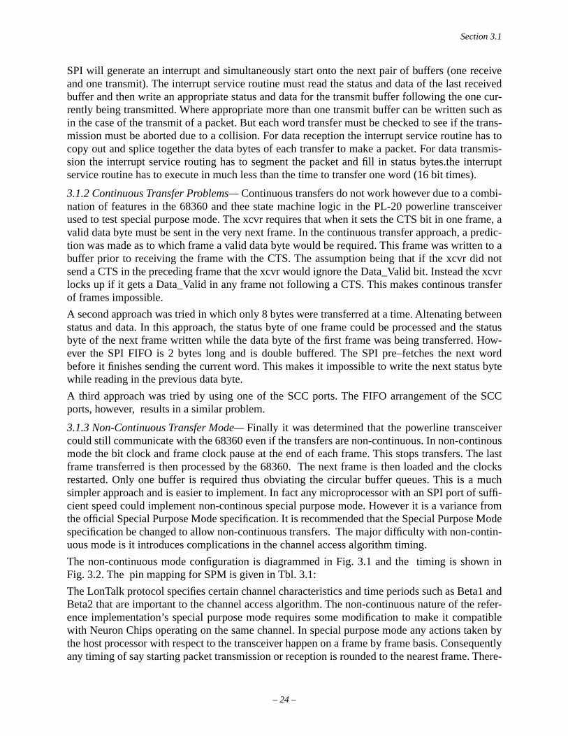
SPI will generate an interrupt and simultaneously start onto the next pair of buffers (one receiveand one transmit). The interrupt service routine must read the status and data of the last receivedbuffer and then write an appropriate status and data for the transmit buffer following the one cur-rently being transmitted. Where appropriate more than one transmit buffer can be written such asin the case of the transmit of a packet. But each word transfer must be checked to see if the trans-mission must be aborted due to a collision. For data reception the interrupt service routine has tocopy out and splice together the data bytes of each transfer to make a packet. For data transmis-sion the interrupt service routing has to segment the packet and fill in status bytes.the interruptservice routine has to execute in much less than the time to transfer one word (16 bit times).
3.1.2 Continuous Transfer Problems— Continuous transfers do not work however due to a combi-nation of features in the 68360 and thee state machine logic in the PL-20 powerline transceiverused to test special purpose mode. The xcvr requires that when it sets the CTS bit in one frame, avalid data byte must be sent in the very next frame. In the continuous transfer approach, a predic-tion was made as to which frame a valid data byte would be required. This frame was written to abuffer prior to receiving the frame with the CTS. The assumption being that if the xcvr did notsend a CTS in the preceding frame that the xcvr would ignore the Data_Valid bit. Instead the xcvrlocks up if it gets a Data_Valid in any frame not following a CTS. This makes continous transferof frames impossible.
A second approach was tried in which only 8 bytes were transferred at a time. Altenating betweenstatus and data. In this approach, the status byte of one frame could be processed and the statusbyte of the next frame written while the data byte of the first frame was being transferred. How-ever the SPI FIFO is 2 bytes long and is double buffered. The SPI pre–fetches the next wordbefore it finishes sending the current word. This makes it impossible to write the next status bytewhile reading in the previous data byte.
A third approach was tried by using one of the SCC ports. The FIFO arrangement of the SCCports, however, results in a similar problem.
3.1.3 Non-Continuous Transfer Mode— Finally it was determined that the powerline transceivercould still communicate with the 68360 even if the transfers are non-continuous. In non-continousmode the bit clock and frame clock pause at the end of each frame. This stops transfers. The lastframe transferred is then processed by the 68360. The next frame is then loaded and the clocksrestarted. Only one buffer is required thus obviating the circular buffer queues. This is a muchsimpler approach and is easier to implement. In fact any microprocessor with an SPI port of suffi-cient speed could implement non-continous special purpose mode. However it is a variance fromthe official Special Purpose Mode specification. It is recommended that the Special Purpose Modespecification be changed to allow non-continuous transfers. The major difficulty with non-contin-uous mode is it introduces complications in the channel access algorithm timing.
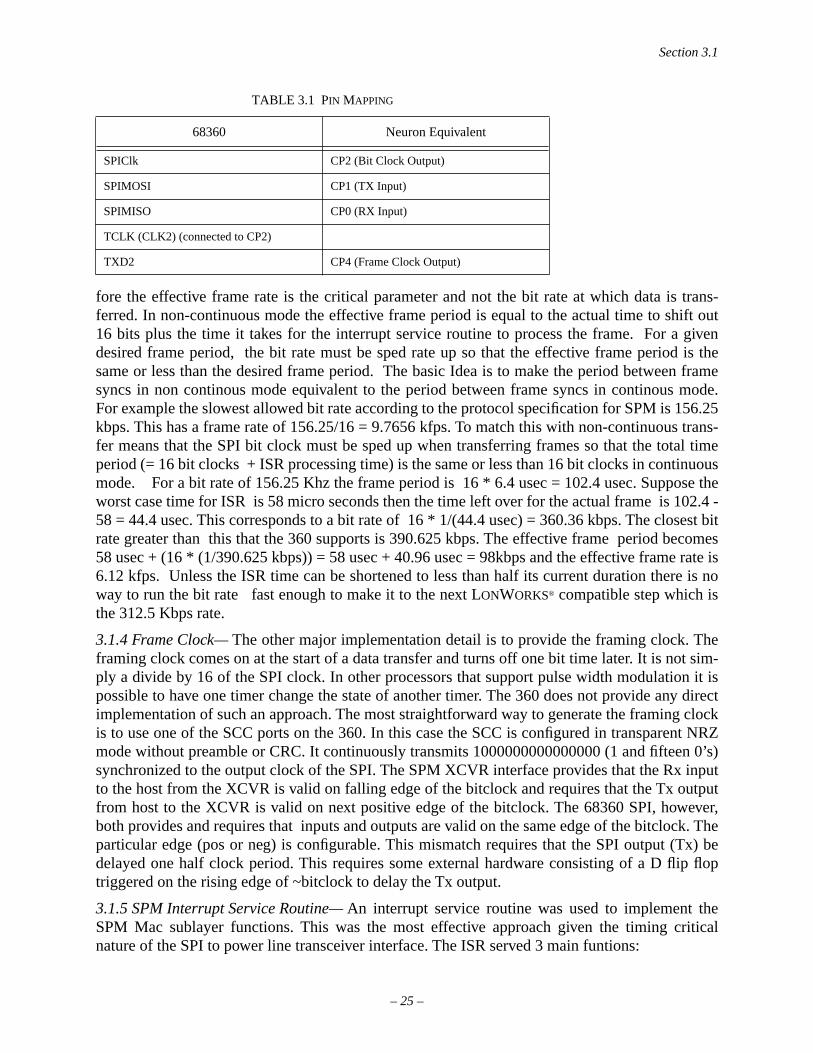
The non-continuous mode configuration is diagrammed in Fig. 3.1 and the timing is shown inFig. 3.2. The pin mapping for SPM is given in Tbl. 3.1:
The LonTalk protocol specifies certain channel characteristics and time periods such as Beta1 andBeta2 that are important to the channel access algorithm. The non-continuous nature of the refer-ence implementation’s special purpose mode requires some modification to make it compatiblewith Neuron Chips operating on the same channel. In special purpose mode any actions taken bythe host processor with respect to the transceiver happen on a frame by frame basis. Consequentlyany timing of say starting packet transmission or reception is rounded to the nearest frame. There-
– 24 –
Section 3.1
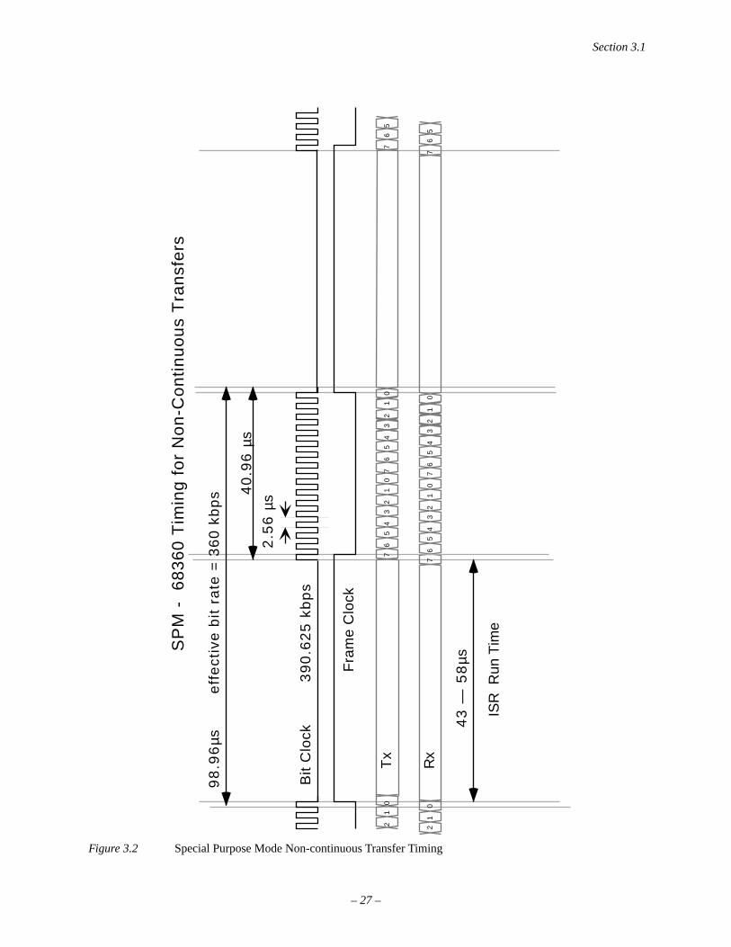
fore the effective frame rate is the critical parameter and not the bit rate at which data is trans-ferred. In non-continuous mode the effective frame period is equal to the actual time to shift out16 bits plus the time it takes for the interrupt service routine to process the frame. For a givendesired frame period, the bit rate must be sped rate up so that the effective frame period is thesame or less than the desired frame period. The basic Idea is to make the period between framesyncs in non continous mode equivalent to the period between frame syncs in continous mode.For example the slowest allowed bit rate according to the protocol specification for SPM is 156.25kbps. This has a frame rate of 156.25/16 = 9.7656 kfps. To match this with non-continuous trans-fer means that the SPI bit clock must be sped up when transferring frames so that the total timeperiod (= 16 bit clocks + ISR processing time) is the same or less than 16 bit clocks in continuousmode. For a bit rate of 156.25 Khz the frame period is 16 * 6.4 usec = 102.4 usec. Suppose theworst case time for ISR is 58 micro seconds then the time left over for the actual frame is 102.4 -58 = 44.4 usec. This corresponds to a bit rate of 16 * 1/(44.4 usec) = 360.36 kbps. The closest bitrate greater than this that the 360 supports is 390.625 kbps. The effective frame period becomes58 usec + (16 * (1/390.625 kbps)) = 58 usec + 40.96 usec = 98kbps and the effective frame rate is6.12 kfps. Unless the ISR time can be shortened to less than half its current duration there is noway to run the bit rate fast enough to make it to the next LONWORKS® compatible step which isthe 312.5 Kbps rate.
3.1.4 Frame Clock— The other major implementation detail is to provide the framing clock. Theframing clock comes on at the start of a data transfer and turns off one bit time later. It is not sim-ply a divide by 16 of the SPI clock. In other processors that support pulse width modulation it ispossible to have one timer change the state of another timer. The 360 does not provide any directimplementation of such an approach. The most straightforward way to generate the framing clockis to use one of the SCC ports on the 360. In this case the SCC is configured in transparent NRZmode without preamble or CRC. It continuously transmits 1000000000000000 (1 and fifteen 0’s)synchronized to the output clock of the SPI. The SPM XCVR interface provides that the Rx inputto the host from the XCVR is valid on falling edge of the bitclock and requires that the Tx outputfrom host to the XCVR is valid on next positive edge of the bitclock. The 68360 SPI, however,both provides and requires that inputs and outputs are valid on the same edge of the bitclock. Theparticular edge (pos or neg) is configurable. This mismatch requires that the SPI output (Tx) bedelayed one half clock period. This requires some external hardware consisting of a D flip floptriggered on the rising edge of ~bitclock to delay the Tx output.
3.1.5 SPM Interrupt Service Routine— An interrupt service routine was used to implement theSPM Mac sublayer functions. This was the most effective approach given the timing criticalnature of the SPI to power line transceiver interface. The ISR served 3 main funtions:
TABLE 3.1 PIN MAPPING
68360 Neuron Equivalent
SPIClk CP2 (Bit Clock Output)
SPIMOSI CP1 (TX Input)
SPIMISO CP0 (RX Input)
TCLK (CLK2) (connected to CP2)
TXD2 CP4 (Frame Clock Output)
– 25 –

Section 3.1
a) SPI transfers
b) SPM transceiver handshake state machine
c) Channel access algorithm state machine
Figure 3.1 Non-continuous Special Purpose Mode Hardware Configuration
Sta
tus
Da
ta
Sta
tus
Da
ta
SP
IIS
R
Re
ceiv
e F
ram
e B
uff
er
Tra
nsm
it F
ram
e B
uff
er
SP
IMIS
O R
X In
put
SP
IMO
SI
SP
ICL
K B
it C
lock
Ou
tpu
t
TC
LK
TX
D
Fra
me
Clo
ck O
utp
ut
SC
C
LPD
U
LPD
U
Spe
cial
Pur
pose
Mod
e 68
360
Impl
emen
tatio
n
Lin
kL
aye
rR
ecei
veQ
ueue
Lin
kL
aye
rT
ran
smit
Que
ue
Lin
kL
aye
rP
rio
rity
Tra
nsm
itQ
ueue
LPD
U
PH
YS
end(
)
MS
B F
irst
MS
B F
irst
D-F
FD
Q
TX
Ou
tpu
t
~B
itClo
ck
Par
alle
lP
ort
Gen
eral
Pur
pose
IO
Pin
~R
eset
XC
VR
Ne
two
rk
Lin
k L
aye
r
– 26 –
Section 3.1
Figure 3.2 Special Purpose Mode Non-continuous Transfer Timing
21
07
65
21
07
65
43
21
07
65
43
21
07
65
Bit
Clo
ck
Fra
me
Clo
ck
Tx
Rx
43
— 5
8µs
2.5
6 µ
s
39
0.6
25
kb
ps
98
.96
µs
ISR
Run
Tim
e
SP
M -
6
83
60
Tim
ing
fo
r N
on
-Co
nti
nu
ou
s T
ran
sfe
rs
40
.96
µs
eff
ect
ive
bit
ra
te =
36
0 k
bp
s
76
54
32
10
76
54
32
10
– 27 –

Section 3.2
The ISR would run at the end of each completed SPM frame transfer. The order of execution ofeach of the ISR functions is as follows: First the received SPI/SPM frame is read in, second thechannel access algorithm state machine is executed including the cycle timer code, third the SPMhandshake state machine is executed, and finally the transmit SPI/SPM frame is written and andSPI transfer is initiated. The order of execution is important as the interaction between the chan-nel access algorithm state machine and SPM state machine assumes that the channel access algo-rithm will go first. A diagram of the channel access algorithm state machine is shown in Fig. 3.3.The SPM state machine is shown in Fig. 3.4.
3.2 Direct Mode (Single Ended)
The Neuron chip uses Bi-Phase space encoding with variable length bit sync preambles (all 1’s)and a single bit (0) for a byte sync preamble. Bi-Phase space encoding uses one transition at thebeginning of each bit time for a 1 and a second transition at the midpoint of a bit time for a 0.Each packet ends with a 16 bit CRC and > 2 bit times of line code violation (no transitions).
The 68360 has four SCC ports. Each port can be configured to automatically support a variety ofprotocols although LONTalk is not one of them. However, most of the functionality needed forthe LONTalk protocol is provided by the SCC ports. An SCC port includes a digital phase lockedloop (DPLL) that can be used for synchronizing clocks. The SCC port can also provide carriersense, encoding and decoding functions and preamble pattern matching. The SCC also providesSDMA access to memory through circular queues.
The attempted 68360 implementation is as follows: The SCC is configured to operate in transpar-ent mode with the DPLL enabled to provide encoding and decoding of FM0 format (same as Bi-phase space encoding). An internal baud rate generator will be used for the nominal bit timeclock. The DPLL will use that for transmission and as the basis for generating the receive syn-chronization clock. The DPLL can be configured to have a base clock rate of 16 times the syncclock at 1.25 Mbps and maximum 32 times for slower channels.
For reception, the preamble sync pattern is set to 1110. The SCC will start dumping bits to areceive buffer as soon as it detects that pattern on the channel. Since LONTalk preambles consistof a variable (depending on the channel type) number of 1’s followed by a zero, the SCC will waituntil the 0. Each receive buffer should be as large as the largest anticipated packet.
The DPLL can be configured so that a idle is indicated after 1.5 bit times of line code violation.An idle channel is indicated by the CS bit in the SCCS register. A change in CS sets the DCC bitin the SCCE and can cause an interrupt. The SCC does not have a direct way of terminating apacket by noticing line code violations. Consequently it could continue dumping bits into thereceive buffer during an idle. The interrupt service routine must manually terminate packet recep-tion and then remove any spurious bits on the end of the packet due to the latency between whenthe packet really ended and the service routine executed. The latency for entering and interruptservice routine on the 68360 is on the order of 30 clock cycles. This is greater than 1 bit time forthe 1.25 Mbps channel (25MHz clock). This makes 1.25 Mbps second operation problematicwithout external hardware. The interrupt service routine may not be able to resolve the true end ofthe packet.
The Idle interrupt service routine must also start checking and timing the length of the idle in thecase that an outgoing packet is waiting. If the required idle time is reached then it can manuallyinitiate transmission of a packet. It must also copy to a transmit buffer any waiting PPDU’s. Amultipurpose I/O pin on one of the 68360 ports can be configured for the collision detect input.
– 28 –

Section 3.2
Figure 3.3 SPM Channel Access Algorithm State Machine. The bottom two unconnected blocks labled ALWAYS and From SPM Handshade reprensent code that is executed later in the ISR that is essential to the channel access algorithm but is not formally part of the state machine code section.
STATE
ConditionAction
StateTransitionKey
Special Purpose Mode Channel Access Algorithm State Machine
BUSY
Channel now idleStart idle timerClear alt path bit flagClear rxValidCRC flagSet Beta1 durationSet PriorityIdle duration
Channel still busySet as post receive or posttransmit
BETA1_IDLE
Channel now busy
Transmit packet ready and altpath bit not yet written
Write alt path bit
Beta 1 time expired and priorityaccess conditions satisfied
Start transmit timer
Beta 1 time expired and priorityaccess conditions not satisfied
Default
PRIORITY_IDLE
Channel now busy
Transmit packet ready and altpath bit not yet written
Write alt path bit
Priority idle time expired andtransmit packet ready
Start transmit timerStart base timerCompute Random Access Slot
Priority idle time expired andtransmit packet not ready
Default
RANDOM_IDLE
Channel now busy
Transmit packet ready and altpath bit not yet written
Write alt path bit
Transmit packet readyStart transmit timerStart base timerCompute Random Access Slot
Default
PRIORITY_WAIT_TX
Channel now busy
Transmit timer expiredAccess approved
Default
RANDOM_WAIT_TX
Channel now busy
Transmit timer expiredAccess approved
Default
Always and base timer expiredRestart base timerDecrement Backlog
START_TX
Channel now busyAccess denied
Transmit packet not readyAccess denied
Default
Always and base timer expiredRestart base timerDecrement Backlog
ALWAYS
State is RANDOM_IDLE andcycle timer restart
Restart cycle timer
DefaultShift cycle timer forward
State is RANDOM_IDLE andcycle timer expired
Restart cycle timerDecrement backlog
From SPM HandshakeValid CRC receive packet
Set cycle timer restartSet valid CRC receiveUpdate backlog with deltaBL
Successful transmit packetSet cycle timer restartUpdate backlog with deltaBL
Collision on transmitIncrement backlog
– 29 –

Section 3.2
Figure 3.4 Special Purpose Mode 68360 to Transceiver Frame Transfer Handshake State Machine
IDLErxFlag
Init CRC & rx byte counterstatus = 0 data = 0
txOnIncrement reset counterstatus = 0 data = 0
writeAltPathBit &&!altPathBitWritten
Write alt path bitSet altPathBitWrittenstatus = 1data = config w alt path bit
tpr && accessApprovedReset tx byte counterstatus = 0x40 data = 0
crw && (0 < cra <= 7)status = cra data = crData
srr && (0 <= sra <= 7)status = 00001sra data = 0
defaultstatus =0 data = 0
RECEIVE!rxFlag
Process end of packetstatus = 0 data = 0
rxDataValidProcess new bytestatus = 0 data = 0
defaultWait for next bytestatus = 0 data = 0
WRITE
!rwAck && crw &&(0 < cra <= 7)
status = cra data = crData
defaultcrw = FALSEstatus = 0 data = 0
rxFlagInit CRC & rx byte counterstatus = 0 data = 0
READ
!rwAck && srr &&(0 <= sra <= 7)
status = 00001sra data = 0
defaultstatus = 0 data = 0
rxFlagInit CRC & rx byte counterstatus = 0 data = 0
rwAcksrData = datasrr = FALSEstatus = 0 data = 0
REQ_TX
clrTxReqFlag && setTxFlag &&txDataCTS
status = 0xA0 data = tpkt[tc]Increment tc
defaultstatus = 0 data = 0
rxFlagInit CRC & rx byte counterstatus = 0 data = 0
clrTxReqFlag && !setTxFlagstatus = 0 data = 0
TRANSMIT
txDataCTS && tc < tlstatus = 0xA0 data = tpkt[tc]Increment tc
defaultreset all counterstpr = FALSEstatus = 0 data = 0
setCollDetProcess collisionstatus = 0 data = 0
txDataCTS && tc >= tlstatus = 0xA0 data = tpkt[tc]Increment tc
txOn && tpr && tc < tl &&resetCount > Limit
status = 0xA0 data = tpkt[tc]Increment tc, resetCountHard reset XCVR
txOn && tpr && tc < tl &&resetCount < Limit
status = 0xA0 data = tpkt[tc]Increment tc, resetCount
DONE_TX
txOn && resetCount > Limitstatus = 0 data = 0Hard reset XCVR
setCollDetProcess collisionstatus = 0 data = 0
defaultstatus = 0 data = 0Process end of TX packet
txOn && resetCount < Limitstatus = 0 data = 0
DEBUGdefault
status = 0 data = 0
MAC Sub-layer to Special Purpose Mode XCVR State Machine
STATE
ConditionAction
StateTransitionKey
– 30 –
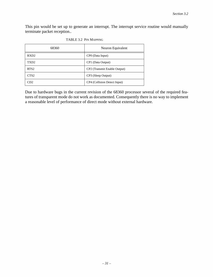
Section 3.2
This pin would be set up to generate an interrupt. The interrupt service routine would manuallyterminate packet reception..
Due to hardware bugs in the current revision of the 68360 processor several of the required fea-tures of transparent mode do not work as documented. Consequently there is no way to implementa reasonable level of performance of direct mode without external hardware.
TABLE 3.2 PIN MAPPING
68360 Neuron Equivalent
RXD2 CP0 (Data Input)
TXD2 CP1 (Data Output)
RTS2 CP2 (Transmit Enable Output)
CTS2 CP3 (Sleep Output)
CD2 CP4 (Collision Detect Input)
– 31 –

Section 4
4 APPLICATION PROGRAMMER’S INTERFACE (API) DESCRIPTION
4.1 Overview
The reference implementation supports most of the important features of a Neuron C programsuch as explicit messages, implicit addressing, network variables, and alias variables. Every efforthas been made to make the porting of Neuron C programs to run under reference implementationeasier. The reference implementation uses modern naming conventions and has hooks for support-ing multiple stacks running on a single processor. Thus, there are differences in the naming ofstructures and fields. For compatibility, structures similar to those in Neuron C are also definedand functions to copy data between the Neuron C format and Reference Implementation formatare provided. Thus an application program can use Neuron C like structures or Reference Imple-mentation defined structures, but not both at the same time. This section describes all the detailsneeded to understand how to write application programs for the reference implementation.
4.2 Compilation
The reference implementation uses several .c and .h files. The application programmer normallyneeds to change only custom.h custom.c and apppgm.c files. The reference implementationincludes a make facility to re-compile everything to create the loadable image. See readme file fordetails regarding compilation, loading, and execution of application program.
4.3 Pragmas
There are no Neuron C equivalent pragma declarations for the reference implementation program.All pragma related initialization can be done using the files custom.h and custom.c. Edit thesefiles and change appropriate values before compiling the code. This section describes each ofthese constants and their proper use. Most of the constants defined are either related to somepragma or related to fields in readOnlyDataStruct. See Technical Device Data book for moredetails.
a) MODEL_NUM - Every node has a model number and reference implementation has beenassigned 128. Normally, there is no need to change this constant unless you need a differentmodel number.
b) MINOR_MODEL_NUM - This is the minor model number. Default is 0. Normally, thereshould be no need to change this value.
c) READ_WRITE_PROTECT - Used to protect areas of memory from read or write using net-work management commands. See Data Book for more details.
d) RUN_WHEN_UNCONF - This is used to indicate whether the application program shouldrun even if the node is in un-configured state. The default is 0 (Do not run). Set it to 1 to runwhen un-configured.
e) NUM_ADDR_TBL_ENTRIES - This specifies number of address table entries. The maxi-mum value is bounded by 0xFFFF. See Sec. 2.6.11 for more details.
f) RECEIVE_TRANS_COUNT - This specifies number of receive transaction records allocatedfor this node. For larger incoming traffic, increase the value. If this value is too small, incom-ing packets could get discarded due to unavailable entry in the receive record pool. If it is toolarge, then the search time for transport, session, and auth layers will increase every timeTPReceive or SNReceive or AuthReceive are called and then the performance degrades.
– 32 –

Section 4.3
g) NV_TABLE_SIZE - This specifies the number of network variable table entries. Set thisbased expected number of network variables used in the application program. For arrays,each entry will consume one network variable table entry. Reference implementation is likehost based node and hence you have up to 4096 entries.
h) NV_ALIAS_TABLE_SIZE - This specifies the number of alias table entries used by thenode. Alias table entries are used for creating alias entries for primary network variables.These alias entries can have their own selector numbers and helps to resolve some bindingproblems that are not allowed otherwise. Unless the binding tool can make use of alias tables,there is no use for these entries unless the binding is done manually.
i) SNVT_SIZE - This specifies the number of bytes allocated for snvt structures. If the node haslot of network variables, you need to increase this space to allow information about thesevariables to be recorded in these structures. See section A.5 of Data Book for more details.
j) APP_OUT_BUF_SIZE - This specifies the number of bytes allocated for application outputbuffers. This field is encoded using the table on page 9-9 of Data Book Rev. 4.
k) APP_IN_BUF_SIZE - This specifies the number of bytes allocated for application input buff-ers.
l) NW_OUT_BUF_SIZE - This specifies the number of bytes allocated for network outputbuffers.
m) NW_IN_BUF_SIZE - This specifies the number of bytes allocated for network input buffers.
n) APP_OUT_Q_CNT - This specifies the number of entries allocated for application outputbuffers. This field is encoded using table on page 9-10 of Data Book Rev. 4.
o) APP_OUT_PRI_Q_CNT - This specifies the number of entries allocated for application pri-ority output buffers.
p) APP_IN_Q_CNT - This specifies the number of entries allocated for application input buff-ers.
q) NW_OUT_Q_CNT - This specifies the number of entries allocated for network output buff-ers.
r) NW_OUT_PRI_Q_CNT - This specifies the number of entries allocated for network priorityoutput buffers.
s) NW_IN_Q_CNT - This specifies the number of entries allocated for network input buffers.
t) NGTIMER_SPCL_VAL - This specifies the receive timer value in seconds used for messageshaving unique id (i.e. Neuron Id) addressing.
u) NON_GROUP_TIMER - This specifies the receive timer value to be used for messages thatdo not use group or unique id addressing. This value is encoded using the table on page 9-17of Data Book Rev. 4. This field is stored in config data structure and hence can be changed bymanagement tools.
v) NM_AUTH - indicates whether network management commands are to be authenticated ornot. 0 => no, 1 => yes.
w) NODE_DOC - This is used to store a nodes self documentation string. It should be a C string.The maximum size is 1023 bytes.
– 33 –
Section 4.3
x) GROUP_SIZE_COMPATIBILITY - This indicates whether the value of group size indicatedin destination address for explicit messages is (actual group size + 1) or actual group size,when the node is not a member of the group. Since the firmware protocol in Neuron Chipsalways reduce the value by 1 to determine the number of responses or acks expected, thevalue should be set to (actual group size + 1). In reference implementation, this can be set toeither (actual group size + 1) or actual group size depending on whether this constant isdefined or not.
y) MAX_NV_ARRAYS - This specifies the maximum number of array network variables thatwill be used in this node. This is needed to help the protocol allocate some space for storing atable for its internal use.
z) MAX_NV_OUT - This specifies the maximum number of outstanding network output vari-ables that are scheduled due to Propagate function calls at any point of time. A queue withthis size is used to schedule network variable updates. If this queue becomes full, further net-work variable update messages (using Propagate) cannot be processed until space becomesavailable in this queue.
aa) MAX_NV_LENGTH - This specifies the maximum number of bytes allocated to capture thevalue of network value variables that are declared as synchronous. When such a variable isupdated and propagated, the current value of the variable is copied into the queue and hencethis value is useful to indicate maximum size. Note that reference implementation does notuse malloc for dynamic allocation after node reset.
ab) MAX_NV_IN - This specifies the maximum number of network input variables that can bescheduled for polling. Every time the application program wants to poll a network input vari-able, it is placed in a queue whose size is determined by this constant.
ac) MAX_DATA_SIZE - This specifies the maximum size of data array in gp->msgOut ormsg_out structure which is used to from explicit messages. This size is independent ofAPP_OUT_BUF_SIZE but does not make sense for this to be any larger.
ad) TS_RESET_DELAY_TIME - This specifies the timer value in milliseconds used in delayingthe transport and session layers for sending any new messages after a power-up or externalreset. This is done to avoid sending messages that could be considered as duplicates andtossed by receiving nodes.
ae) MALLOC_SIZE - This specifies the size of array used for allocating storage for all thequeues, receive record pools etc. by the protocol. Clearly, the proper value depends on manyof the values defined in custom.h and hence only the application programmer can determinethis value. If this value is too small, some layer will be unable to do a proper Reset forcing thenode to return from main. One can set this to a large value, run the application, and thencheck the value of gp->mallocUsedSize to compute a more accurate value. Alternatively,once can go through Reset functions of all layers and compute the appropriate value manu-ally. Trial and error approach is probably easier.
In addition to the constants defined in custom.h, the application programmer can also indicateother information about a node in custom.c. This includes information such as the Neuron Id ofthe node, the number of domains for the node, the subnet/node number, authentication key, etc.These are self-explanatory and the details of the structure definition can be found in custom.h.
– 34 –
Section 4.4
4.4 Initialization
Every application program should provide a function called AppInit that will be called once by themain. void AppInit(void);
The purpose of this function is to initialize variables, register network variables, tags etc. onceduring power-up. These initialization are such that they are not performed after every reset.
4.5 Reset
Every application program should provide a function called AppReset that will be called everytime the node is reset. void AppReset(void);
The purpose of this function is to initialize variables after every reset or do any other work theapplication program finds appropriate.
4.6 Application Program
Every application program should include <node.h> header file and provide a function calledDoApp. void DoApp(void);
This function is the entry point for the actual application program. The scheduler calls DoApp()once per pass through the round robin schedule loop. The DoApp() function has four responsibili-ties:
a) Process incoming messages, if any. Upon completion of processing a message, call msgFree().
b) Process incoming responses, if any. Upon completion of processing a response, call respFree().
c) Perform application specific processing. (e.g sending messages, responses, updating network variables etc.)
d) Return to the round robin scheduler quickly. This is necessary to allow the protocol stack to process new messages. If the application needs to perform a large amount of processing, it must break the processing up into small pieces, and process one piece per call.
Messages and responses must be processed in a timely function, preferably on each pass throughDoApp. If the application messages are not processed quickly enough, messages may be lostbecause all application input buffers are full.
The user application must not define the entry point "main()". The reference implementationscheduler defines the entry point.
In addition to the above two functions, the application program must define the following func-tions:void MsgCompletes(Status stat, MsgTag tag);
This function is called whenever a transaction initiated by the applicationis completed. stat will be either SUCCESS or FAILURE. This function has thesame role as the msg_completes event of the Neuron C program.
void NVUpdateCompletes(Status stat, int16 nvIndex, int16 nvArrayIndex);This function is called whenever a network variable update or poll eithersucceeds or fails. stat will be either SUCCESS or FAILURE. nvIndex is theindex of the network variable. nvArrayIndex is the array index if nvIndex
– 35 –

Section 4.7
corresponds to a network array variable.void NVUpdateOccurs(int16 nvIndex, int16 nvArrayIndex);
This function is called whenever a network variable has been updated. ThenvIndex is the index of the variable that was updated. nvArrayIndex is arrayindex if nvIndex corresponds to an array network variable.
void Wink(void);This function is called when the node receives the wink network managementmessage. The application can do whatever it wants.
void OfflineEvent(void);This function is called just before the application is placed offline.
void OnlineEvent(void);This function is called just before the application is placed online.
4.7 Explicit Messages and Responses
Since the reference implementation has hooks for supporting multiple stacks, a global structure isused for each stack. Before calling any function, the scheduler sets pointers gp, eep, and nmp topoint to the global stack data, EEPROM data, and neuron memory mapped data. Within the globalstack data, the reference implementation has variables msgIn, msgOut, respIn, respOut, msgRe-ceive, and respReceive. These are similar to the ones defined in Neuron C. msgReceive is a bool-ean variable that is set to true whenever there is a message available in msgIn. Similarly,respReceive is true if there is a response to be received in respIn.
To make porting of existing Neuron C programs easier, the reference implementation can createvariables such as msg_in, msg_out etc if the constant NEURON_STRUCTURES_NEEDED isdefined in lontalk.h. If this constant is defined then the application program should only use vari-ables similar to the ones defined for Neuron C. Otherwise, the application programs should vari-ables defined in reference implementation (gp->msgIn, gp->msgOut etc). Some of thesestructures have additional fields in reference implementation that should be filled by the applica-tion program (for example, len field is required for msg_out). See api.h for details of these struc-tures. The following descriptions use Neuron C variables but the same holds for variables such asgp->msgOut that are unique to reference implementation.
extern msg_in_type msg_in; // For incoming messageextern msg_out_type msg_out; // For outgoing explicit messageextern resp_in_type resp_in; // For incoming responseextern resp_out_type resp_out; // For outgoing responseextern nv_in_addr_type nv_in_addr; // The source address of incoming messageextern int16 nv_array_index; // array index for nv array var update
Boolean MsgAlloc(void); // Returns TRUE if explicit message can be formed.Boolean msg_alloc(void); // For Neuron C compatibility. Same as MsgAlloc.Boolean MsgAllocPriority(void); // Similar to MsgAlloc for priority messages.Boolean msg_alloc_priority(void); // For Neuron C Compatibility.void MsgSend(void); // To send an explicit message.void msg_send(void); // For Neuron C Compatibility.void MsgCancel(void); // Does nothing. For backward compatibility.void msg_cancel(void); // For Neuron C Compatibility.void MsgFree(void); // Releases data in msgIn to receive new one.void msg_free(void); // For Neuron C Compatibility.Boolean msgReceive(void); // TRUE if there is msg in msgIn.Boolean msg_receive(void); // For Neuron C Compatibility.
– 36 –

Section 4.7
Boolean RespAlloc(void); // Returns TRUE if response can be formed.Boolean resp_alloc(void); // For Neuron C Compatibility.void RespSend(void); // Send the response in resp_out.void resp_send(void); // For Neuron C Compatibility.void RespCancel(void); // Does nothing. For backward compatibility.void resp_cancel(void); // For Neuron C Compatibility.void RespFree(void); // Releases data in respIn to receive new one.void resp_free(void); // For Neuron C Compatibility.Boolean RespReceive(void); // Check if there is any response to receive.Boolean resp_receive(void); // For Neuron C Compatibility.
4.7.1 Receiving Messages— extern msg_in_type msg_in; // For incoming messageBoolean msg_receive(void); // For Neuron C Compatibility.void msg_free(void); // For Neuron C Compatibility.
When the protocol receives a message addressed to this node, the data from the message is writtento the msg_in structure, and the next call to function msg_receive() will return TRUE. The appli-cation uses the data in msg_in, and then calls msg_free(). The msg_free function enables a newmessage to be placed in msg_in. When another message is received, or if a message is alreadybuffered, it is placed in msg_in, and the next call to the funciton msg_receive() will return TRUE.Thus the application can get at most one message per cycle. If the application calls msg_receive()but does not call msg_free(), the reference implementation will automatically call msg_free().
4.7.2 Receiving Responses— extern resp_in_type resp_in; // For incoming responseBoolean resp_receive(void); // For Neuron C Compatibility.void resp_free(void); // For Neuron C Compatibility.
When the protocol receives a response to a request made by this node, the data from the responseis written to the resp_in structure, and the next call to function resp_receive() will returnTRUE. The application uses the data in resp_in, and then calls resp_free(). The resp_freefunction enables a new response to be placed in resp_in. When another response is received, or ifa response is already buffered, it is placed in resp_in, and the next call to the functionresp_receive() will return TRUE. Thus the application can get at most one response per cycle. Ifthe application calls resp_receive() but does not call resp_free(), the reference implementationwill automatically call resp_free().
4.7.3 Sending Messages— extern msg_out_type msg_out;// For outgoing explicit messageBoolean msg_alloc(void); // For Neuron C compatibility. Same as MsgAlloc.Boolean msg_alloc_priority(void); // For Neuron C Compatibility.void msg_send(void); // For Neuron C Compatibility.
Before sending a message, the application calls msg_alloc() or msg_alloc_priority() for apriority message. If the allocation function returns FALSE, then an application output buffer is notavailable, and application must try again later. These functions simply check if the correspondingapplication output buffer has space for storing a message or not.
When the allocation function returns TRUE, an application message out buffer is allocated for thecurrent message. The application sets various fields in msg_out to construct the message. The
– 37 –
Section 4.8
field len is new and is required. The value of len is the number of bytes stored in data array. Theremaining fields are as done in Neuron C. When the message in msg_out is ready to be sent, theapplication calls msg_send(), and the message is sent. There is no need to call the functionmsg_cancel() as it does nothing. The structure msg_out is re-initialized by the reference imple-mentation after each msg_send().
In order for the application program to receive message completion, the application programshould define the function: void MsgCompletes(Status stat, MsgTag tag);
When a message completes, the API calls the user defined function MsgCompletes() to return thecompletion status of the message. The tag parameter is the value from the tag field of the msg_outstructure.
4.7.4 Sending Responses— extern resp_out_type resp_out; // For outgoing responseBoolean resp_alloc(void); // For Neuron C Compatibility.void resp_send(void); // For Neuron C Compatibility.
When the application receives a message containing a request, the application returns a response.Before sending a response, the application calls resp_alloc(). If resp_alloc() returnsFALSE, then an application response buffer is not available, and application must try again later.The function simply checks if there is space for a new response in the response queue for sessionlayer.
When resp_alloc() returns TRUE, the application can send a response. The application sets vari-ous fields in resp_out to construct the response. The field len is required and represents the num-ber of bytes in data array of the response. The field req_id is used to indicate the request id of thecorresponding request. This is used for retrieving the matching request from the receive recordpool. The value of 0 is an invalid request id and is used by the reference implementation to detectthe fact that the application program did not initialize this field and hence it automatically sets it tothe request id of the request last received in msg_in. The field null_response can be set to true toindicate that it is a null response (one which is not sent out). This field is used by the session layerto mark the request as done. A well behaved application program is expected to respond to everyrequest. A null response is provided for this purpose. The reference implementation will continueto work without any problem even if a response is not sent by the application program.When theresponse in resp_out is ready to be sent, the application calls resp_send(), and the response issent. There is no need to call the function resp_cancel() as it does nothing. The structure resp_outis re-initialized by the reference implementation after each resp_send().
4.8 Network Variables
Network variables are declared in the application program in a different way than done in theNeuron C program. The API defines the following structure to help the declaration of networkvariables.typedef struct { Bits priority : 1; /* TRUE or FALSE */ Bits direction : 1; /* NV_INPUT or NV_OUTPUT */ Bits selectorHi : 6; /* Present only for non-bindable */
– 38 –

Section 4.8
Bits selectorLo : 8; /* Present only for non-bindable */ Bits bind : 1; /* 1 => bindable 0 ==> nobindable */ Bits turnaround : 1; /* TRUE or FALSE */ Bits service : 2; /* ACKD, UNACKD_RPT, UNACKD */ Bits auth : 1; /* TRUE or FALSE */ Bits : 3; /* Unused */ Bits explodeArray : 1; /* Explode arrays in SNVT structure */ Bits nvLength : 7; /* Length of network variable in bytes. For arrays, give the size of each item. */
uint8 snvtDesc; /* snvtDesc_struct in byte form. Big_Endian */ uint8 snvtExt; /* Extension record. Big_Endian. */ uint8 snvtType; /* 0 => non-SNVT variable. */ uint8 rateEst; uint8 maxrEst; uint16 arrayCnt; /* 0 for simple variables. dim for arrays. */ char *nvName; /* Name of the network variable */ char *nvSdoc; /* Sel-doc string for the variable */ void *varAddr; /* Address of the variable. */} NVDefinition;
For each network variable, the application must define a structure and initialize it with appropriatevalues. This structure is similar to the network variable declarations with bind information. Thereare no defaults and hence you should provide all the values. For each network variable, the appli-cation should also declare storage for that variable and an index to communicate with API. Forexample, nint intIn; /* Polled network input variable. */NVDefinition intInDef = { FALSE, NV_INPUT, 0, 0, 1, FALSE, ACKD, FALSE, 0, sizeof(nint), 0xA0, 0x30, 0, 0, 0, 0, "intIn", "intInSD", &intIn};int16 intInIndex;
Note that the type nint is used. In place of nint, one can use almost any type. The following pre-defined types are convenient to use to declare neuron equivalent types.
typedef char int8;typedef short int int16;typedef long int int32;typedef unsigned char uint8;typedef unsigned short int uint16;typedef unsigned long int uint32;/* Neuron C Definitions for int long etc. */typedef int8 nshort;typedef int8 nint; typedef uint8 nuint;typedef uint8 nushort;typedef int16 nlong;
– 39 –

Section 4.9
typedef uint16 nulong;
The network variable must be registered explicitly using the function AddNV in AppInit function.Even though you can initialize the storage for the variable in the declaration statement, you shouldalso do it in AppReset function to ensure that the variable has those values after every node reset(unless the logic calls for otherwise). The following code illustrates this procedure.
Status AppInit(void){ /* Register Network variables */ intOutIndex = AddNV(&intOutDef); longOutIndex = AddNV(&longOutDef); intArrayOutIndex = AddNV(&intArrayOutDef); intInIndex = AddNV(&intInDef); longInIndex = AddNV(&longInDef); intArrayInIndex = AddNV(&intArrayInDef);
/* Make sure we were successful in registering all variables */ if (intOutIndex == -1 || longOutIndex == -1 || intArrayOutIndex == -1 || intInIndex == -1 || longInIndex == -1 || intArrayInIndex == -1) { return(FAILURE); } tag0 = NewMsgTag(BINDABLE); tag1 = NewMsgTag(BINDABLE); /* Make sure we got the tags successfully */ if (tag0 == -1 || tag1 == -1) { return(FAILURE); } return(SUCCESS);}
AddNV returns -1 if it fails to register. It is a good idea to test for this and return FAILURE forAppInit to indicate to the scheduler that there was a problem.
4.9 Network Variable Related Functions
There are several functions in the API to support registering, updating, polling, propagating ofnetwork variables. They are defined below:
/*************************************************************************Adds a new network variable. This involves adding an entry into nvConfig-Table, nvFixedTable, SNVT information, if present etc. The return value is the index assigned to the variable. For arrays, each element is like a sep-arate network variable. So, multiple entries are added to the
– 40 –

Section 4.9
tables. However, only the base index is returned.**************************************************************************/int16 AddNV(NVDefinition *dp);/* NVUpdateCompletes is called when an nv update or nv poll completes. The 2nd parameter is the array index for array variables, 0 for simple variables. */void NVUpdateCompletes(Status stat, int16 nvIndex, int16 nvArrayIndex);
/* NVUpdateOccurs is called when an input nv has been changed. The 2nd parameter is the array index for array variables, 0 for simple variables. */void NVUpdateOccurs(int16 nvIndex, int16 nvArrayIndex);
/* To send all network output variables in the node. Polled or not, Use Propagate function. */void Propagate(void);
/* To send one simple network variable or a whole array */void PropagateNV(int16 nvIndex);
/* To send an array element or any other simple variable.*/void PropagateArrayNV(int16 arrayNVIndex, int16 index);
/* To poll all input network variables */void Poll(void);
/* To poll a specific simple input network variable or an array */void PollNV(int16 nvIndex);
/* Poll a specific array element or any other simple variable. */void PollArrayNV(int16 arrayNVIndex, int16 index);
The reference implementation supports implicit messages only through the use of explicit calls toone of the three Propagate functions. Since there is no Neuron C like compiler, there is no way tomodify the code based on the fact that a variable got updated and hence the need for these explicitcalls. The Poll functions are as used in Neuron C.
A network variable update may involve one primary and 0 or more alias entries. For each, theaddress table entry can have difference address formats. Thus, it is possible that several nv updatemessages are sent for one network variable update. A network variable update is said to succeed ifevery transaction scheduled for that variable succeeds. The value of the parameter stat in NVUp-dateCompletes indicates whether the network variable update succeeded or failed. Note that it isnot a boolean variable but rather of type Status. So, you should compare against SUCCESS orFAILURE.
A network variable poll may involve one primary and 0 or more alias entries. For each, theaddress table entry can have different address formats. Thus, it is possible that several nv pollmessages are sent for one network variable poll. A network variable poll is said to succeed if it isturnaround only or every transaction (not including turnaround) succeeds and at least oneresponse contains valid data. Thus, a turnaround only poll will always succeed. As another exam-ple, if a network variable poll is both turnaround and connected to a network output variable inanother node and that node returns null data, then the poll will fail. The value of the parameter statin NVUpdateCompletes indicates whether the network variable poll succeeded or failed. Note that
– 41 –

Section 4.10
it is not a boolean variable but rather of type Status. So, you should compare against SUCCESS orFAILURE.
4.10 Network Variables and Address Table Entries
Due to limitation of 4 bits for address table index in network variable config structure and the factthat network management tools may not support more than 15 address table entries, the referenceimplementation does not support implicit addressing for network variables using address tableentries beyond the 15th entry. It is conceivable for someone to modify the code so that this is pos-sible and at the same time the code is backward compatible. One easy way this can possibly bedone is to use an additional table for the network variables and store only the index of the addresstable entry that should be used for each network variable. This entry can be used only if the origi-nal network variable table indicates that the network variable is not bound to any address tableentry. If both indices are unbound, then the network variable is not bound to an address tableentry. The functions that handle nv update and poll should be modified to take care of this changeby setting a local variable representing the address table index appropriately. Note that the addresstable entries should be initialized by the application program somehow (either using custom.c orsome other way). This is just a suggestion and there is no guarantee that this technique work wellas it has not been tried. Even if it works, care should be taken to make the code inter-operable withexisting tools and neuron nodes. It is best to use this for internal use when the situation demandsthe use of network variables with lots of address table entries.
4.11 Message Tags
The application program can define either bindable tags or non-bindable tags in the applicationprogram. The following function is used to declare new tags./* To get a new message tag. NewMsgTag(BIND) or NewMsgTag(NOBIND) */MsgTag NewMsgTag(BindNoBind bindStatusIn);
The number of bindable tags is usually bounded by 15 but can be up to 0xFF. The number of bind-able tags declared in a node is stored in a field in SNVT structures and is accessible to manage-ment tools. Thus, one should limit the number of bindable tags to no more than 15 for the purposeof interoperability. Each bindable tag consumes an address table entry and hence it is wise not touse up all these entries if you also want to bind network variables. Bindable tags are used forimplicit addressing. An application program can use large number of non-bindable tags. The limiton number of non-bindable tags is 0xFFFF - NUM_ADDR_TBL_ENTRIES.
The reference implementation will use implicit addressing if the tag value supplied in msg_outstructure is less than NUM_ADDR_TBL_ENTRIES and the destination address in msg_out isunbound or turnaround. Since tag is just a number, an application can use tag values > 15 but lessthan NUM_ADDR_TBL_ENTRIES to use implicit addressing. Such tags should be declaredexplicitly. However, these address table entries should be explicitly initialized by the applicationprogram either using custom.c or some other way. Non-bindable tags are primarily used for corre-lation with message completion.
4.12 Miscellaneous Functions
The following are some miscellaneous functions that an application program can call./* Application can call this fn to put itself offline */void GoOffline(void);/* Appplication can call this fn to put itself unconfigured */void GoUnconfigured(void);
– 42 –

Section 4.13
/* To send a service pin message */Boolean ServicePinMessage(void);
4.13 Alias Tables
The reference implementation does support the concept of alias tables that are used to performmore complex binding of network variables. Some older tools may not support the use of aliastables. However, an application can initialize the alias tables based on known indices (Networkvariables are registered in the order in which they are given starting with an index value of 0)using custom.c file. Alternatively, a modern management tool that supports alias tables can beused. In either case, the application program should define the number of alias table entries avail-able in custom.h. This information is stored in SNVT structures and is available to network man-agement tools.
4.14 Software Timers
The reference implementation allows the application program to use any number of software tim-ers. All software timers are maintained using a single hardware timer. The software timers are notautomatically updated. The application needs to call either UpdateMsTimer or MsTimerExpired.Only millisecond timers are supported. The following is the definition for the software timerstructure./* Software Timer definition. */typedef struct{ uint32 curTimerValue; /* Number of clock ticks left in timer. */ uint32 lastUpdatedTime; /* The time when the timer was last updated. */ Boolean expired; /* TRUE => it has already expired. */} MsTimer;
The functions that are related to the use of software timers are:void SetMsTimer(MsTimer *timerOut, uint16 initValueIn);void UpdateMsTimer(MsTimer *timerInOut);Boolean MsTimerExpired(MsTimer *timerInOut);
SetMsTimer is used to initialize the timer to given number of milliseconds. UpdateMsTimer isused to update the timer. There is no harm to update a timer that has already expired. The fieldcurTimerValue indicates the number of milliseconds left before expiry. Instead of using UpdateM-sTimer, an application program can use MsTimerExpired (similar to timer expiration event in Neu-ron C) to check if a timer has expired. MsTimerExpired will return true only during the first timethe timer expired. If the timer has already expired, the function MsTimerExpired will return false.MsTimerExpired calls UpdateMsTimer and checks the curTimerValue to determine whether thetimer expired or not. The reference implementation does not support repeating timers. The appli-cation program should re-initialize the timer upon expiry.
Example: MsTimer myTimer; SetMsTimer(&myTimer, 1000); /* For 1 second */ /* Do some processing */ : if (MsTimerExpired(&myTimer))
– 43 –

Section 4.14
{ /* Do whatever you want */ : SetMsTimer(&myTimer, 1000); /* Reset if needed */ }
– 44 –

Section 5
5 REFERENCES Arnewsh 95 SBC360/EC User’s Manual Revision 1, Arnewsh Inc.1995
Echelon 95 Lontalk Protocol Specification Version 3.0 078-0125-01A ,Echelon Corporation1995
Echelon 96 LonWorks Protocol Layer 1 Timing, Preliminary, Echelon Corporation 1996
Echelon 91 Neuron Chip Special-Purpose Mode Transceiver Interface Specification, LonWorks Engineering Bulletin, Echelon Corporation 1991
Echelon 94 NV Connectivity Extensions: The Aliasing Alternative, Revision 2.2 April 1994, Echelon Corpora-tion
Harbison 95 Harbison S. P. and Steele G. L. Jr., C A Reference Manual, Prentice Hall 199? ISBN 0-13-110933-2
Motorola 97 LonWorks Technology Device Data DL159/D Rev4, Motorola 1997.
Motorola 95 MC68360 Quad Integrated Communications Controller User’s Manual MC68360UM/AD REV 1, Motorola 1995
Motorola 90 M68300 Family CPU32 Central Processor Unit Reference Manual CPU32RM/AS REV1, Motor-ola 1991
SDS 96a CrossCode User Guide Version 7, Software Development Systems 1996
SDS 96b SingleStep User Guide Version 7, Software Development Systems 1996
– 45 –
Related Documents